EP4208237B1 - Aerosol high flow therapy apparatus - Google Patents
Aerosol high flow therapy apparatus Download PDFInfo
- Publication number
- EP4208237B1 EP4208237B1 EP21769661.6A EP21769661A EP4208237B1 EP 4208237 B1 EP4208237 B1 EP 4208237B1 EP 21769661 A EP21769661 A EP 21769661A EP 4208237 B1 EP4208237 B1 EP 4208237B1
- Authority
- EP
- European Patent Office
- Prior art keywords
- aerosol
- treatment system
- extraction
- controller
- delivery
- Prior art date
- Legal status (The legal status is an assumption and is not a legal conclusion. Google has not performed a legal analysis and makes no representation as to the accuracy of the status listed.)
- Active
Links
Images





Classifications
-
- A—HUMAN NECESSITIES
- A61—MEDICAL OR VETERINARY SCIENCE; HYGIENE
- A61M—DEVICES FOR INTRODUCING MEDIA INTO, OR ONTO, THE BODY; DEVICES FOR TRANSDUCING BODY MEDIA OR FOR TAKING MEDIA FROM THE BODY; DEVICES FOR PRODUCING OR ENDING SLEEP OR STUPOR
- A61M16/00—Devices for influencing the respiratory system of patients by gas treatment, e.g. ventilators; Tracheal tubes
- A61M16/06—Respiratory or anaesthetic masks
- A61M16/0666—Nasal cannulas or tubing
- A61M16/0672—Nasal cannula assemblies for oxygen therapy
- A61M16/0677—Gas-saving devices therefor
-
- A—HUMAN NECESSITIES
- A61—MEDICAL OR VETERINARY SCIENCE; HYGIENE
- A61M—DEVICES FOR INTRODUCING MEDIA INTO, OR ONTO, THE BODY; DEVICES FOR TRANSDUCING BODY MEDIA OR FOR TAKING MEDIA FROM THE BODY; DEVICES FOR PRODUCING OR ENDING SLEEP OR STUPOR
- A61M16/00—Devices for influencing the respiratory system of patients by gas treatment, e.g. ventilators; Tracheal tubes
- A61M16/0087—Environmental safety or protection means, e.g. preventing explosion
- A61M16/009—Removing used or expired gases or anaesthetic vapours
-
- A—HUMAN NECESSITIES
- A61—MEDICAL OR VETERINARY SCIENCE; HYGIENE
- A61M—DEVICES FOR INTRODUCING MEDIA INTO, OR ONTO, THE BODY; DEVICES FOR TRANSDUCING BODY MEDIA OR FOR TAKING MEDIA FROM THE BODY; DEVICES FOR PRODUCING OR ENDING SLEEP OR STUPOR
- A61M11/00—Sprayers or atomisers specially adapted for therapeutic purposes
-
- A—HUMAN NECESSITIES
- A61—MEDICAL OR VETERINARY SCIENCE; HYGIENE
- A61M—DEVICES FOR INTRODUCING MEDIA INTO, OR ONTO, THE BODY; DEVICES FOR TRANSDUCING BODY MEDIA OR FOR TAKING MEDIA FROM THE BODY; DEVICES FOR PRODUCING OR ENDING SLEEP OR STUPOR
- A61M15/00—Inhalators
-
- A—HUMAN NECESSITIES
- A61—MEDICAL OR VETERINARY SCIENCE; HYGIENE
- A61M—DEVICES FOR INTRODUCING MEDIA INTO, OR ONTO, THE BODY; DEVICES FOR TRANSDUCING BODY MEDIA OR FOR TAKING MEDIA FROM THE BODY; DEVICES FOR PRODUCING OR ENDING SLEEP OR STUPOR
- A61M16/00—Devices for influencing the respiratory system of patients by gas treatment, e.g. ventilators; Tracheal tubes
- A61M16/0087—Environmental safety or protection means, e.g. preventing explosion
- A61M16/009—Removing used or expired gases or anaesthetic vapours
- A61M16/0093—Removing used or expired gases or anaesthetic vapours by adsorption, absorption or filtration
-
- A—HUMAN NECESSITIES
- A61—MEDICAL OR VETERINARY SCIENCE; HYGIENE
- A61M—DEVICES FOR INTRODUCING MEDIA INTO, OR ONTO, THE BODY; DEVICES FOR TRANSDUCING BODY MEDIA OR FOR TAKING MEDIA FROM THE BODY; DEVICES FOR PRODUCING OR ENDING SLEEP OR STUPOR
- A61M16/00—Devices for influencing the respiratory system of patients by gas treatment, e.g. ventilators; Tracheal tubes
- A61M16/0096—High frequency jet ventilation
-
- A—HUMAN NECESSITIES
- A61—MEDICAL OR VETERINARY SCIENCE; HYGIENE
- A61M—DEVICES FOR INTRODUCING MEDIA INTO, OR ONTO, THE BODY; DEVICES FOR TRANSDUCING BODY MEDIA OR FOR TAKING MEDIA FROM THE BODY; DEVICES FOR PRODUCING OR ENDING SLEEP OR STUPOR
- A61M16/00—Devices for influencing the respiratory system of patients by gas treatment, e.g. ventilators; Tracheal tubes
- A61M16/021—Devices for influencing the respiratory system of patients by gas treatment, e.g. ventilators; Tracheal tubes operated by electrical means
- A61M16/022—Control means therefor
-
- A—HUMAN NECESSITIES
- A61—MEDICAL OR VETERINARY SCIENCE; HYGIENE
- A61M—DEVICES FOR INTRODUCING MEDIA INTO, OR ONTO, THE BODY; DEVICES FOR TRANSDUCING BODY MEDIA OR FOR TAKING MEDIA FROM THE BODY; DEVICES FOR PRODUCING OR ENDING SLEEP OR STUPOR
- A61M16/00—Devices for influencing the respiratory system of patients by gas treatment, e.g. ventilators; Tracheal tubes
- A61M16/06—Respiratory or anaesthetic masks
-
- A—HUMAN NECESSITIES
- A61—MEDICAL OR VETERINARY SCIENCE; HYGIENE
- A61M—DEVICES FOR INTRODUCING MEDIA INTO, OR ONTO, THE BODY; DEVICES FOR TRANSDUCING BODY MEDIA OR FOR TAKING MEDIA FROM THE BODY; DEVICES FOR PRODUCING OR ENDING SLEEP OR STUPOR
- A61M16/00—Devices for influencing the respiratory system of patients by gas treatment, e.g. ventilators; Tracheal tubes
- A61M16/06—Respiratory or anaesthetic masks
- A61M16/0605—Means for improving the adaptation of the mask to the patient
- A61M16/0616—Means for improving the adaptation of the mask to the patient with face sealing means comprising a flap or membrane projecting inwards, such that sealing increases with increasing inhalation gas pressure
- A61M16/0622—Means for improving the adaptation of the mask to the patient with face sealing means comprising a flap or membrane projecting inwards, such that sealing increases with increasing inhalation gas pressure having an underlying cushion
-
- A—HUMAN NECESSITIES
- A61—MEDICAL OR VETERINARY SCIENCE; HYGIENE
- A61M—DEVICES FOR INTRODUCING MEDIA INTO, OR ONTO, THE BODY; DEVICES FOR TRANSDUCING BODY MEDIA OR FOR TAKING MEDIA FROM THE BODY; DEVICES FOR PRODUCING OR ENDING SLEEP OR STUPOR
- A61M16/00—Devices for influencing the respiratory system of patients by gas treatment, e.g. ventilators; Tracheal tubes
- A61M16/06—Respiratory or anaesthetic masks
- A61M16/0683—Holding devices therefor
-
- A—HUMAN NECESSITIES
- A61—MEDICAL OR VETERINARY SCIENCE; HYGIENE
- A61M—DEVICES FOR INTRODUCING MEDIA INTO, OR ONTO, THE BODY; DEVICES FOR TRANSDUCING BODY MEDIA OR FOR TAKING MEDIA FROM THE BODY; DEVICES FOR PRODUCING OR ENDING SLEEP OR STUPOR
- A61M16/00—Devices for influencing the respiratory system of patients by gas treatment, e.g. ventilators; Tracheal tubes
- A61M16/10—Preparation of respiratory gases or vapours
- A61M16/1005—Preparation of respiratory gases or vapours with O2 features or with parameter measurement
-
- A—HUMAN NECESSITIES
- A61—MEDICAL OR VETERINARY SCIENCE; HYGIENE
- A61M—DEVICES FOR INTRODUCING MEDIA INTO, OR ONTO, THE BODY; DEVICES FOR TRANSDUCING BODY MEDIA OR FOR TAKING MEDIA FROM THE BODY; DEVICES FOR PRODUCING OR ENDING SLEEP OR STUPOR
- A61M16/00—Devices for influencing the respiratory system of patients by gas treatment, e.g. ventilators; Tracheal tubes
- A61M16/10—Preparation of respiratory gases or vapours
- A61M16/105—Filters
- A61M16/1055—Filters bacterial
-
- A—HUMAN NECESSITIES
- A61—MEDICAL OR VETERINARY SCIENCE; HYGIENE
- A61M—DEVICES FOR INTRODUCING MEDIA INTO, OR ONTO, THE BODY; DEVICES FOR TRANSDUCING BODY MEDIA OR FOR TAKING MEDIA FROM THE BODY; DEVICES FOR PRODUCING OR ENDING SLEEP OR STUPOR
- A61M16/00—Devices for influencing the respiratory system of patients by gas treatment, e.g. ventilators; Tracheal tubes
- A61M16/10—Preparation of respiratory gases or vapours
- A61M16/1075—Preparation of respiratory gases or vapours by influencing the temperature
-
- A—HUMAN NECESSITIES
- A61—MEDICAL OR VETERINARY SCIENCE; HYGIENE
- A61M—DEVICES FOR INTRODUCING MEDIA INTO, OR ONTO, THE BODY; DEVICES FOR TRANSDUCING BODY MEDIA OR FOR TAKING MEDIA FROM THE BODY; DEVICES FOR PRODUCING OR ENDING SLEEP OR STUPOR
- A61M16/00—Devices for influencing the respiratory system of patients by gas treatment, e.g. ventilators; Tracheal tubes
- A61M16/10—Preparation of respiratory gases or vapours
- A61M16/14—Preparation of respiratory gases or vapours by mixing different fluids, one of them being in a liquid phase
- A61M16/16—Devices to humidify the respiration air
-
- A—HUMAN NECESSITIES
- A61—MEDICAL OR VETERINARY SCIENCE; HYGIENE
- A61M—DEVICES FOR INTRODUCING MEDIA INTO, OR ONTO, THE BODY; DEVICES FOR TRANSDUCING BODY MEDIA OR FOR TAKING MEDIA FROM THE BODY; DEVICES FOR PRODUCING OR ENDING SLEEP OR STUPOR
- A61M16/00—Devices for influencing the respiratory system of patients by gas treatment, e.g. ventilators; Tracheal tubes
- A61M16/20—Valves specially adapted to medical respiratory devices
-
- A—HUMAN NECESSITIES
- A61—MEDICAL OR VETERINARY SCIENCE; HYGIENE
- A61M—DEVICES FOR INTRODUCING MEDIA INTO, OR ONTO, THE BODY; DEVICES FOR TRANSDUCING BODY MEDIA OR FOR TAKING MEDIA FROM THE BODY; DEVICES FOR PRODUCING OR ENDING SLEEP OR STUPOR
- A61M15/00—Inhalators
- A61M15/0086—Inhalation chambers
-
- A—HUMAN NECESSITIES
- A61—MEDICAL OR VETERINARY SCIENCE; HYGIENE
- A61M—DEVICES FOR INTRODUCING MEDIA INTO, OR ONTO, THE BODY; DEVICES FOR TRANSDUCING BODY MEDIA OR FOR TAKING MEDIA FROM THE BODY; DEVICES FOR PRODUCING OR ENDING SLEEP OR STUPOR
- A61M16/00—Devices for influencing the respiratory system of patients by gas treatment, e.g. ventilators; Tracheal tubes
- A61M16/06—Respiratory or anaesthetic masks
- A61M16/0666—Nasal cannulas or tubing
- A61M16/0672—Nasal cannula assemblies for oxygen therapy
-
- A—HUMAN NECESSITIES
- A61—MEDICAL OR VETERINARY SCIENCE; HYGIENE
- A61M—DEVICES FOR INTRODUCING MEDIA INTO, OR ONTO, THE BODY; DEVICES FOR TRANSDUCING BODY MEDIA OR FOR TAKING MEDIA FROM THE BODY; DEVICES FOR PRODUCING OR ENDING SLEEP OR STUPOR
- A61M16/00—Devices for influencing the respiratory system of patients by gas treatment, e.g. ventilators; Tracheal tubes
- A61M16/08—Bellows; Connecting tubes ; Water traps; Patient circuits
- A61M16/0808—Condensation traps
-
- A—HUMAN NECESSITIES
- A61—MEDICAL OR VETERINARY SCIENCE; HYGIENE
- A61M—DEVICES FOR INTRODUCING MEDIA INTO, OR ONTO, THE BODY; DEVICES FOR TRANSDUCING BODY MEDIA OR FOR TAKING MEDIA FROM THE BODY; DEVICES FOR PRODUCING OR ENDING SLEEP OR STUPOR
- A61M16/00—Devices for influencing the respiratory system of patients by gas treatment, e.g. ventilators; Tracheal tubes
- A61M16/10—Preparation of respiratory gases or vapours
- A61M16/1045—Devices for humidifying or heating the inspired gas by using recovered moisture or heat from the expired gas
-
- A—HUMAN NECESSITIES
- A61—MEDICAL OR VETERINARY SCIENCE; HYGIENE
- A61M—DEVICES FOR INTRODUCING MEDIA INTO, OR ONTO, THE BODY; DEVICES FOR TRANSDUCING BODY MEDIA OR FOR TAKING MEDIA FROM THE BODY; DEVICES FOR PRODUCING OR ENDING SLEEP OR STUPOR
- A61M16/00—Devices for influencing the respiratory system of patients by gas treatment, e.g. ventilators; Tracheal tubes
- A61M16/10—Preparation of respiratory gases or vapours
- A61M16/105—Filters
- A61M16/106—Filters in a path
- A61M16/1065—Filters in a path in the expiratory path
-
- A—HUMAN NECESSITIES
- A61—MEDICAL OR VETERINARY SCIENCE; HYGIENE
- A61M—DEVICES FOR INTRODUCING MEDIA INTO, OR ONTO, THE BODY; DEVICES FOR TRANSDUCING BODY MEDIA OR FOR TAKING MEDIA FROM THE BODY; DEVICES FOR PRODUCING OR ENDING SLEEP OR STUPOR
- A61M16/00—Devices for influencing the respiratory system of patients by gas treatment, e.g. ventilators; Tracheal tubes
- A61M16/20—Valves specially adapted to medical respiratory devices
- A61M16/201—Controlled valves
-
- A—HUMAN NECESSITIES
- A61—MEDICAL OR VETERINARY SCIENCE; HYGIENE
- A61M—DEVICES FOR INTRODUCING MEDIA INTO, OR ONTO, THE BODY; DEVICES FOR TRANSDUCING BODY MEDIA OR FOR TAKING MEDIA FROM THE BODY; DEVICES FOR PRODUCING OR ENDING SLEEP OR STUPOR
- A61M16/00—Devices for influencing the respiratory system of patients by gas treatment, e.g. ventilators; Tracheal tubes
- A61M16/0003—Accessories therefor, e.g. sensors, vibrators, negative pressure
- A61M2016/0015—Accessories therefor, e.g. sensors, vibrators, negative pressure inhalation detectors
- A61M2016/0018—Accessories therefor, e.g. sensors, vibrators, negative pressure inhalation detectors electrical
- A61M2016/0024—Accessories therefor, e.g. sensors, vibrators, negative pressure inhalation detectors electrical with an on-off output signal, e.g. from a switch
-
- A—HUMAN NECESSITIES
- A61—MEDICAL OR VETERINARY SCIENCE; HYGIENE
- A61M—DEVICES FOR INTRODUCING MEDIA INTO, OR ONTO, THE BODY; DEVICES FOR TRANSDUCING BODY MEDIA OR FOR TAKING MEDIA FROM THE BODY; DEVICES FOR PRODUCING OR ENDING SLEEP OR STUPOR
- A61M16/00—Devices for influencing the respiratory system of patients by gas treatment, e.g. ventilators; Tracheal tubes
- A61M16/0003—Accessories therefor, e.g. sensors, vibrators, negative pressure
- A61M2016/0027—Accessories therefor, e.g. sensors, vibrators, negative pressure pressure meter
-
- A—HUMAN NECESSITIES
- A61—MEDICAL OR VETERINARY SCIENCE; HYGIENE
- A61M—DEVICES FOR INTRODUCING MEDIA INTO, OR ONTO, THE BODY; DEVICES FOR TRANSDUCING BODY MEDIA OR FOR TAKING MEDIA FROM THE BODY; DEVICES FOR PRODUCING OR ENDING SLEEP OR STUPOR
- A61M2205/00—General characteristics of the apparatus
- A61M2205/33—Controlling, regulating or measuring
- A61M2205/3331—Pressure; Flow
- A61M2205/3334—Measuring or controlling the flow rate
-
- A—HUMAN NECESSITIES
- A61—MEDICAL OR VETERINARY SCIENCE; HYGIENE
- A61M—DEVICES FOR INTRODUCING MEDIA INTO, OR ONTO, THE BODY; DEVICES FOR TRANSDUCING BODY MEDIA OR FOR TAKING MEDIA FROM THE BODY; DEVICES FOR PRODUCING OR ENDING SLEEP OR STUPOR
- A61M2205/00—General characteristics of the apparatus
- A61M2205/33—Controlling, regulating or measuring
- A61M2205/3331—Pressure; Flow
- A61M2205/3337—Controlling, regulating pressure or flow by means of a valve by-passing a pump
-
- A—HUMAN NECESSITIES
- A61—MEDICAL OR VETERINARY SCIENCE; HYGIENE
- A61M—DEVICES FOR INTRODUCING MEDIA INTO, OR ONTO, THE BODY; DEVICES FOR TRANSDUCING BODY MEDIA OR FOR TAKING MEDIA FROM THE BODY; DEVICES FOR PRODUCING OR ENDING SLEEP OR STUPOR
- A61M2205/00—General characteristics of the apparatus
- A61M2205/36—General characteristics of the apparatus related to heating or cooling
- A61M2205/3673—General characteristics of the apparatus related to heating or cooling thermo-electric, e.g. Peltier effect, thermocouples, semi-conductors
Definitions
- the present invention relates to aerosol therapy, especially high flow therapy.
- High flow nasal therapy will typically deliver an air/oxygen/aerosol mix to a patient at a rate that exceeds their peak inspiratory rate.
- An example is 50LPM treatment vs. an average inhalation of about 20 LPM (averaged across the inhalation period of a breath) with a peak inhalation of about 35LPM.
- Aerosol delivered into the high flow stream will be homogeneously distributed. Therefore, the excess airflow contains aerosolised drug that the patient cannot absorb and this results in reduced efficiency. Also, this excess will disperse into the surrounding room air. This is a fugitive emission that potentially exposes clinicians, patients and visitors to aerosolised drugs and patient-generated pathogens.
- the high flow therapy may continue to deliver to the nasal cavity. A portion of this flow will travel into the cavity and exit the patient's mouth, and this flow augments the exhalation flowrate and has the potential to collect patient pathogens. The remainder of the flow will exit the cavity via the nostrils, but prior to this it also can collect pathogens.
- WO2015/155342A (Stamford Devices Ltd) and WO2019/007950A (Stamford Devices Ltd) describe HFNT systems, in which aerosol is delivered primarily during reduced gas flow periods, in order to increase efficiency and reduce losses.
- US2012/285455 (Varga et al ) describes a mask for patient ventilation.
- US2004/244799 (Landis ) describes a tube seal adapter for face masks.
- WO2018/204969 (P & M Hebbard PTY) describes a sealing pad for a respiratory mask.
- WO2019/159063 (Fisher & Paykel ) describes a mask which is fitted over a nasal prong interface.
- WO2017/004404 (Vapotherm) Describes a nasal cannula.
- US2014/0251333 (BURK et al ) describes an exhalation scavenging mask.
- US9,186,474 (Rollins, III ) describes a multi-function oxygen mask.
- WO2005/118036 (Chathampally Y. G. ) describes systems and methods for administration of drugs and medications).
- WO2008/116165 (Next Safety) describes methods and systems of delivering medication via inhalation.
- the invention addresses the problem of achieving effective aerosol treatment with reduction or elimination of gas losses, particularly for high flow treatment.
- the invention provides a system as set out in claim 1, and optional features as set out in claims 2-14.
- a patient interface 1 comprises an annular soft seal base 2 configured to fit around a patient's mouth and nose with a large contact surface of resilient material which is suited to skin contact.
- the base 2 has a relatively rigid core surrounded on at least the patient side with soft material for patient facial contact.
- the base spine supports a prong receiver 3 extending across the base 2, and being of a plastics material having a rugged strength to support attachment of a nasal prong head 4 with prongs 5 at the end of tubing 6 for delivery of high flow gas and aerosol to the nostrils.
- Fig. 2 shows that the interface also includes a shell 10 which fits with a seal to the base 2 and the support 3 to form an enclosed volume around the patient's mouth and nasal area.
- Fig. 3 shows an extraction head 20 which has an L-shaped conduit 21 with a flange 22 configured to fit to a cylindrical port 11 of the shell.
- Fig. 4 shows the full interface 1, with all of these components in place, together with a lead 25 from a pressure sensor within the volume formed by the base 2 and the shell 10.
- the pressure sensor is attached to the inside surface of the shell 10.
- the patient interface is modular, the soft seal base 2 attaching to the patient's head with securing head straps 8.
- the support 3 supports the prong head 4 with the prongs 5 correctly aligned. It is envisaged that in other embodiments the prong support is self-supporting by way of head straps rather than being attached to the soft seal base, especially for uses without extraction.
- the soft seal base 2 is placed on the face first and a comfortable sealing surface is established. This establishes a gas-tight seal and provides a support mechanism for the high flow therapy tubing, and the clinician can conveniently and accurately set up the patient's nasal prongs 3 secured to the soft seal base 2. The fit of the prongs 5 can be checked and adjusted.
- the shell 10 can now be assembled.
- the perimeter of the shell 10 interfaces with the base such that it self-locates and forms a seal
- the soft seal base 2 providing a means of securing the shell 10 in place by for example elastic straps, hook-and-loop fasteners, or clips. It is preferred that the shell fit by way of a snap-fit connection with resilient edges.
- the shell 10, nasal prongs 4/5, and the soft seal base 2 are profiled such that the high flow therapy tubing and head 4 can enter from either the left or the right, and a seal is still established without the need for an additional part.
- an additional capping feature can be provided.
- the shell 10 preferably includes one or more vents to prevent an excessive negative pressure drop within the volume formed by the base 2 and the shell 10 due to extraction. These are located away from exhalation / exhaust airstreams of the mouth and the nostrils.
- the shell 10 has a port 11 to attach a means of suction, in this case the extraction head 20.
- the position of the extraction port 11 is such that in use it is opposed to the mouth and nostrils for optimal collection of exhaled / exhausted gasses and particles.
- the vent or vents may not be in the mask itself, and could for example be part of an exhalation tube.
- vent The benefit of a vent is that, because the mask is very effective at sealing the space around the nose and mouth, the operation of the high flow system and the forced extraction system does not cause the system to be too intrusive by acting effectively akin to a ventilator, in which all inhalation and exhalation is controlled. There may for example be a very soft opening on an inhale valve to not affect breathing, and/or a pressure release valve for safely in case of reduced extraction.
- the vent may have a suitable filter to block outflow of unwanted droplets to avoid contamination of the environment.
- the shell also has a retainer to attach a sensor for measuring the internal mask pressure.
- Figs. 6 to 8 shows test results for ambient aerosol particles in the environment surrounding the patient's head for with the mask and system shown in Fig. 5 .
- This mask is conventional in terms of how it is configured to engage the face, simply a flexible clear polymer with holes cut to take the HFNT delivery and extraction hoses. It does not have the benefits of the mask of Figs. 1 to 4 .
- Fig. 6 demonstrates an extraction flowrate in the region of 80LPM to 100LPM is required to capture approximately all aerosol particles, in these examples with treatment at 50LPM.
- Fig. 6 demonstrates the major differences between the bands of 7- to 135 LPM, 40 LPM, and no extraction. In the latter there is essentially no difference between situations where the mask is present and is not, because of losses around the edges of the mask.
- Fig. 7 shows more detail for the higher extraction rate band, with the vertical axes showing particles in the tens per cm 3 .
- Fig. 9 is a summary histogram showing that there is a liner relationship between extraction flowrate and percentage of particles captured., reaching full capture at about 90LPM extraction.
- ⁇ Lower Fit' outperforms the ⁇ Nominal Fit' in terms of capture of emissions (94.8% vs. 88.7%).
- the degree of sealing between the mask and the face affects rate of emission capture for a given extraction rate.
- ⁇ Closed Fit' is the same as ⁇ Lower Fit' except that there is sealing at the cheeks.
- Figs. 10 to 12 displays the distribution of the nasal pressure peaks, which occur during exhalation, with and without extraction.
- the average difference is a reduction of 0.3mBar when extraction is applied; the difference of the maximums is 0.53mBar.
- Fig. 12 displays the distribution of the nasal pressure troughs (these occur during inhalation) with and without extraction.
- the average difference is a reduction of 0.68mBar when extraction is applied; the difference of the minimums is also 0.68mBar.
- the patient interface 1 can connect to a standalone aerosol / high flow therapy device 100 by a tubing set 101 as depicted in Fig. 13 .
- a heated humidified air/ O 2 mixture is delivered on a tube 200, and flow is split by a valve 201 into an aerosol branch 202 with a nebulizer 203 and a parallel bypass branch 204.
- the branches merge into a common tube 205 which leads to the interface 1.
- the aerosol delivery path can include an aerosol chamber having an increased volume to slow down the flowrate at the point of aerosol delivery
- the valve 201 can dynamically throttle the flowrate, and can dynamically divert the flowrate to provide scenarios such as:
- Step-down aerosol delivery when switching to the aerosol path 202 during inhalation, the average flowrate is reduced. This will improve dose efficiently.
- the period of reduced flowrate is short to prevent de-recruitment effects.
- the system controller can adapt the baseline extraction to match the high flow therapy setting.
- the controller can be programmed to dynamically change the extraction rate to match the breath pattern, as illustrated in Fig. 15 . This can maximise the effectiveness of extraction, and therefore reduce the required extraction rate. This has the benefit of reducing the impact on the treatment pressure, and also reduces the extraction source requirements.
- An advantageous part of the extraction system is that there is filtration in line with the extracted airflow to capture any pathogens or drug before it is vented to the ambient room.
- This can be a standard commercial filter that can be changed out by the clinicians. Due to the large levels of humidity in the expelled gas, the filter will become saturated, and the filter regime adapted accordingly.
- the system can determine the actual flowrate based off the mask pressure readings. Or, additional flow and pressure sensors could be employed on the system side of the filter. The system can increase the power supplied to the extraction source to keep the extraction flowrate consistent over time as the filter approaches saturation.
- a condenser can be employed to take vapour out of the extracted gas prior to it reaching the filter. This can prolong the life of the filter.
- the condensing mechanism is preferably such that the surfaces that make contact with the extracted gasses are part of a disposable circuit.
- a heat pump (for example using a Peltier heat exchanger) can be employed to increase the rate of condensing, as illustrated in Fig. 16 . The heat collected in this exchange can be employed in heating of the high flow therapy delivered to the patient. This would have energy saving benefits.
- the mask is provided as a pre-assembled component, perhaps using a sizing chart to allow a clinician to preconfigure and position nasal prongs.
- the mask if it does not have a removable shell may have an access flap to allow adjustment of the nasal prongs.
- any interface which supports the HFNT delivery and extraction and provides a closed or near-closed environment around the mouth and nose is advantageous as described above with reference to Figs. 5 to 12 and 14 to 16 , and where the interface of Figs. 1 to 4 and 13 is used it enhances the closed nature of this volume around the nose and mouth.
Landscapes
- Health & Medical Sciences (AREA)
- Engineering & Computer Science (AREA)
- Life Sciences & Earth Sciences (AREA)
- Anesthesiology (AREA)
- Pulmonology (AREA)
- General Health & Medical Sciences (AREA)
- Heart & Thoracic Surgery (AREA)
- Hematology (AREA)
- Biomedical Technology (AREA)
- Animal Behavior & Ethology (AREA)
- Public Health (AREA)
- Veterinary Medicine (AREA)
- Emergency Medicine (AREA)
- Otolaryngology (AREA)
- Ecology (AREA)
- Environmental & Geological Engineering (AREA)
- Environmental Sciences (AREA)
- Biodiversity & Conservation Biology (AREA)
- Bioinformatics & Cheminformatics (AREA)
- Respiratory Apparatuses And Protective Means (AREA)
- Infusion, Injection, And Reservoir Apparatuses (AREA)
- Measurement Of The Respiration, Hearing Ability, Form, And Blood Characteristics Of Living Organisms (AREA)
- Medicinal Preparation (AREA)
Description
- The present invention relates to aerosol therapy, especially high flow therapy.
- High flow nasal therapy (HFNT) will typically deliver an air/oxygen/aerosol mix to a patient at a rate that exceeds their peak inspiratory rate. An example is 50LPM treatment vs. an average inhalation of about 20 LPM (averaged across the inhalation period of a breath) with a peak inhalation of about 35LPM. Aerosol delivered into the high flow stream will be homogeneously distributed. Therefore, the excess airflow contains aerosolised drug that the patient cannot absorb and this results in reduced efficiency. Also, this excess will disperse into the surrounding room air. This is a fugitive emission that potentially exposes clinicians, patients and visitors to aerosolised drugs and patient-generated pathogens.
- Also, during exhalation (typically through the mouth), the high flow therapy may continue to deliver to the nasal cavity. A portion of this flow will travel into the cavity and exit the patient's mouth, and this flow augments the exhalation flowrate and has the potential to collect patient pathogens. The remainder of the flow will exit the cavity via the nostrils, but prior to this it also can collect pathogens.
-
WO2015/155342A (Stamford Devices Ltd) andWO2019/007950A (Stamford Devices Ltd) describe HFNT systems, in which aerosol is delivered primarily during reduced gas flow periods, in order to increase efficiency and reduce losses.US2012/285455 (Varga et al ) describes a mask for patient ventilation.US2004/244799 (Landis ) describes a tube seal adapter for face masks.WO2018/204969 (P & M Hebbard PTY) describes a sealing pad for a respiratory mask.WO2019/159063 (Fisher & Paykel ) describes a mask which is fitted over a nasal prong interface.WO2017/004404 (Vapotherm) Describes a nasal cannula.US2014/0251333 (BURK et al ) describes an exhalation scavenging mask.US9,186,474 (Rollins, III WO2005/118036 (Chathampally Y. G. ) describes systems and methods for administration of drugs and medications).WO2008/116165 (Next Safety) describes methods and systems of delivering medication via inhalation. - The invention addresses the problem of achieving effective aerosol treatment with reduction or elimination of gas losses, particularly for high flow treatment.
- The invention provides a system as set out in
claim 1, and optional features as set out in claims 2-14. - The invention will be more clearly understood from the following description of some embodiments thereof, given by way of example only with reference to the accompanying drawings in which:
-
Figs. 1 to 4 are perspective views of an aerosol high flow mask being applied in four steps, respectively; -
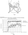
Fig. 5 is a diagram of a mask in position on a demonstration patient head model used for testing; -
Fig. 6 is a plot of bench test results showing particle numbers vs. time determined by an aerodynamic particle analyser for the set-up ofFig. 5 and 50LPM High Flow therapy, and -
Fig. 7 is a plot of bench test results showing particle measurements with time for various high flow rates, also for the set-up ofFig. 5 and in this case showing in more detail the plots for the higher-level extraction of 70 to 135 LPM; -
Fig. 8 is a plot, also for this set-up, showing percentage of particles captured with extraction flow rate; -
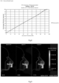
Fig. 9 shows fluid flows detected by imaging sensors, coded to illustrate volumetric velocity within the mask for nominal mask fit, lower mask fit, and closed mask fit; -
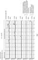
Fig. 10 is a set of plots of extraction flowrate with time for a set-up as shown inFig. 5 and with a nasal pressure sensor added; -
Fig. 11 is a histogram of peak nasal pressure for extraction being turned on and off, and -
Fig. 12 is a histogram of minimum nasal pressure for extraction turned on and off; -
Fig. 13 is a diagram showing the mask ofFigs. 1 to 4 in place, together with a controller; -
Fig. 14 is a flow diagram showing how reduced flow is achieved during inhalation and the aerosol chamber limb is bypassed during inhalation; -
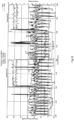
Fig. 15 is a pair of plots showing dynamic extraction and pressure monitoring, showing relationship between extraction and breath flows, in which extraction is matched to aerosol flow; and -
Fig. 16 is a diagram showing flows of humidified and heated air and O2 towards the mask and extracted humid breath which is dried in the extraction direction by virtue of a heat recovery condenser and a heat exchanger which recovers heat for humidification. - Referring to
Fig. 1 apatient interface 1 comprises an annularsoft seal base 2 configured to fit around a patient's mouth and nose with a large contact surface of resilient material which is suited to skin contact. Thebase 2 has a relatively rigid core surrounded on at least the patient side with soft material for patient facial contact. The base spine supports aprong receiver 3 extending across thebase 2, and being of a plastics material having a rugged strength to support attachment of anasal prong head 4 withprongs 5 at the end oftubing 6 for delivery of high flow gas and aerosol to the nostrils. -
Fig. 2 shows that the interface also includes ashell 10 which fits with a seal to thebase 2 and thesupport 3 to form an enclosed volume around the patient's mouth and nasal area.Fig. 3 shows anextraction head 20 which has an L-shaped conduit 21 with aflange 22 configured to fit to acylindrical port 11 of the shell. -
Fig. 4 shows thefull interface 1, with all of these components in place, together with alead 25 from a pressure sensor within the volume formed by thebase 2 and theshell 10. The pressure sensor is attached to the inside surface of theshell 10. - The patient interface is modular, the
soft seal base 2 attaching to the patient's head with securinghead straps 8. Thesupport 3 supports theprong head 4 with theprongs 5 correctly aligned. It is envisaged that in other embodiments the prong support is self-supporting by way of head straps rather than being attached to the soft seal base, especially for uses without extraction. - The
soft seal base 2 is placed on the face first and a comfortable sealing surface is established. This establishes a gas-tight seal and provides a support mechanism for the high flow therapy tubing, and the clinician can conveniently and accurately set up the patient'snasal prongs 3 secured to thesoft seal base 2. The fit of theprongs 5 can be checked and adjusted. - The
shell 10 can now be assembled. The perimeter of theshell 10 interfaces with the base such that it self-locates and forms a seal, thesoft seal base 2 providing a means of securing theshell 10 in place by for example elastic straps, hook-and-loop fasteners, or clips. It is preferred that the shell fit by way of a snap-fit connection with resilient edges. Theshell 10,nasal prongs 4/5, and thesoft seal base 2 are profiled such that the high flow therapy tubing andhead 4 can enter from either the left or the right, and a seal is still established without the need for an additional part. In another embodiment an additional capping feature can be provided. - The
shell 10 preferably includes one or more vents to prevent an excessive negative pressure drop within the volume formed by thebase 2 and theshell 10 due to extraction. These are located away from exhalation / exhaust airstreams of the mouth and the nostrils. Theshell 10 has aport 11 to attach a means of suction, in this case theextraction head 20. The position of theextraction port 11 is such that in use it is opposed to the mouth and nostrils for optimal collection of exhaled / exhausted gasses and particles. The vent or vents may not be in the mask itself, and could for example be part of an exhalation tube. The benefit of a vent is that, because the mask is very effective at sealing the space around the nose and mouth, the operation of the high flow system and the forced extraction system does not cause the system to be too intrusive by acting effectively akin to a ventilator, in which all inhalation and exhalation is controlled. There may for example be a very soft opening on an inhale valve to not affect breathing, and/or a pressure release valve for safely in case of reduced extraction. The vent may have a suitable filter to block outflow of unwanted droplets to avoid contamination of the environment. - The shell also has a retainer to attach a sensor for measuring the internal mask pressure.
-
Figs. 6 to 8 shows test results for ambient aerosol particles in the environment surrounding the patient's head for with the mask and system shown inFig. 5 . This mask is conventional in terms of how it is configured to engage the face, simply a flexible clear polymer with holes cut to take the HFNT delivery and extraction hoses. It does not have the benefits of the mask ofFigs. 1 to 4 . -
Fig. 6 demonstrates an extraction flowrate in the region of 80LPM to 100LPM is required to capture approximately all aerosol particles, in these examples with treatment at 50LPM.Fig. 6 demonstrates the major differences between the bands of 7- to 135 LPM, 40 LPM, and no extraction. In the latter there is essentially no difference between situations where the mask is present and is not, because of losses around the edges of the mask.Fig. 7 shows more detail for the higher extraction rate band, with the vertical axes showing particles in the tens per cm3.Fig. 9 is a summary histogram showing that there is a liner relationship between extraction flowrate and percentage of particles captured., reaching full capture at about 90LPM extraction. - The positioning of the extraction port opposite the patient's mouth affects the rate of emission capture for a given extraction rate. In
Fig. 9 , the `Lower Fit' outperforms the `Nominal Fit' in terms of capture of emissions (94.8% vs. 88.7%). The degree of sealing between the mask and the face affects rate of emission capture for a given extraction rate. InFig. 9 `Closed Fit' is the same as `Lower Fit' except that there is sealing at the cheeks. At the same level of extraction (60 LPM) versus the same emission flowrate (50LPM, there is no breath in this example) the `Closed Fit' outperforms the `Lower Fit' in term of capture of emissions (97.7% vs. 94.8%). - The effect of extraction on the nasal cavity has been investigated. A test setup as shown in
Fig. 5 but with addition of a nasal pressure sensor involved: - Delivery of humified high flow @ 50LPM
- Pressure tube inserted into nasal cavity
- Extraction flowrate either Off or @100LPM
- Flowmeter in-line with extraction source.
- The results of this are illustrated in
Figs. 10 to 12 , which displays the distribution of the nasal pressure peaks, which occur during exhalation, with and without extraction. The average difference is a reduction of 0.3mBar when extraction is applied; the difference of the maximums is 0.53mBar. -
Fig. 12 displays the distribution of the nasal pressure troughs (these occur during inhalation) with and without extraction. The average difference is a reduction of 0.68mBar when extraction is applied; the difference of the minimums is also 0.68mBar. - These results demonstrate the advantages of decreasing extraction during exhalation and not having any extraction during inhalation.
- Major advantages of the invention include:
- Flexible patient-engaging side of the
base 2 provides consistent sealing, especially allowing successful extraction at lower flow rates. - A predictable seal allows less safety factor buffer on the applied extraction rate.
- Less extraction allows less pressure drop, less noise, more extraction source options, controlled vent ports.
- Maximise extraction for a given extraction flowrate.
- Avoidance of occlusion with patient's face.
- Reduced wind noise / wind feeling
- Sized to alleviate pressure drop by a predictable quantity
- Modularity, allowing fitting of the base to be secured to head and adjusted for sealing and comfort independent of the therapy.
- Allows clinical access to setup / check/ change prongs.
- Pressure Port.
- Provides means of measuring pressure internal to the mask.
- Can be used as a safety measure.
- Can be used to detect the breath and dynamically control the extraction rate.
- Allows for more effective extraction with reduced impact on pressure drop.
- The
patient interface 1 can connect to a standalone aerosol / highflow therapy device 100 by atubing set 101 as depicted inFig. 13 . This allows breath-synchronised step-down aerosol delivery. As illustrated inFig. 14 a heated humidified air/ O2 mixture is delivered on atube 200, and flow is split by avalve 201 into anaerosol branch 202 with anebulizer 203 and a parallel bypass branch 204. The branches merge into acommon tube 205 which leads to theinterface 1. - In some examples, the aerosol delivery path can include an aerosol chamber having an increased volume to slow down the flowrate at the point of aerosol delivery
- The
valve 201 can dynamically throttle the flowrate, and can dynamically divert the flowrate to provide scenarios such as: - Full bypass, normal high flow treatment with no aerosol.
- No bypass, open throttle, continuous aerosol delivery.
- No bypass, open throttle, breath synchronised aerosol delivery (pressure sensor used to detect breath pattern).
- Breath-synchronised bypass: divert through bypass during exhalation. Nebuliser is continuously on allowing aerosol to accumulate in the chamber. During inhalation divert the flow through the chamber for increased aerosol concentration.
- Step-down aerosol delivery: when switching to the
aerosol path 202 during inhalation, the average flowrate is reduced. This will improve dose efficiently. The period of reduced flowrate is short to prevent de-recruitment effects. There is a ramp down / ramp up of the reduced flowrate, and these ramps can be controlled / modulated to minimise de-recruitment and discomfort. - The system controller can adapt the baseline extraction to match the high flow therapy setting. The controller can be programmed to dynamically change the extraction rate to match the breath pattern, as illustrated in
Fig. 15 . This can maximise the effectiveness of extraction, and therefore reduce the required extraction rate. This has the benefit of reducing the impact on the treatment pressure, and also reduces the extraction source requirements. - An advantageous part of the extraction system is that there is filtration in line with the extracted airflow to capture any pathogens or drug before it is vented to the ambient room. This can be a standard commercial filter that can be changed out by the clinicians. Due to the large levels of humidity in the expelled gas, the filter will become saturated, and the filter regime adapted accordingly. The system can determine the actual flowrate based off the mask pressure readings. Or, additional flow and pressure sensors could be employed on the system side of the filter. The system can increase the power supplied to the extraction source to keep the extraction flowrate consistent over time as the filter approaches saturation.
- A condenser can be employed to take vapour out of the extracted gas prior to it reaching the filter. This can prolong the life of the filter. The condensing mechanism is preferably such that the surfaces that make contact with the extracted gasses are part of a disposable circuit. A heat pump (for example using a Peltier heat exchanger) can be employed to increase the rate of condensing, as illustrated in
Fig. 16 . The heat collected in this exchange can be employed in heating of the high flow therapy delivered to the patient. This would have energy saving benefits. - No Fugitive emissions of treatment drug
- No spreading of patient pathogens
- Increased drug efficiency
- Increased drug rate
- The invention is not limited to the embodiments described but may be varied in construction and detail within the scope of the claims. For example, it is envisaged that the mask is provided as a pre-assembled component, perhaps using a sizing chart to allow a clinician to preconfigure and position nasal prongs. The mask, if it does not have a removable shell may have an access flap to allow adjustment of the nasal prongs. The performance features and advantages described for an interface having conventional features apply to an interface of
Figs. 1 to 4 , and it is expected that performance would be better because of the enhanced sealing and other advantages described with reference toFigs. 1 to 4 . Irrespective of the interface used, any interface which supports the HFNT delivery and extraction and provides a closed or near-closed environment around the mouth and nose is advantageous as described above with reference toFigs. 5 to 12 and14 to 16 , and where the interface ofFigs. 1 to 4 and13 is used it enhances the closed nature of this volume around the nose and mouth.
Claims (14)
- An aerosol treatment system comprising:a patient interface (1) to cover a patient's mouth and nose,an aerosol delivery apparatus (4, 6),a high flow treatment system (200 - 205) linked with the patient interface (1),a controller (100),a heater and a humidifier, separately or combined, to provide a heated humidified air/O2 mixture (200) delivered to the patient interface (1), andsensors for detecting patient breathing,wherein the controller (100) is configured to control delivery of aerosol to provide breath-synchronised aerosol delivery,characterized in that the system comprises:
a valve (201) arranged to split delivery flow into an aerosol branch (202) with a nebulizer (203) and a parallel bypass branch (204), and the branches merge into a common tube (205) which leads to the patient interface (1). - An aerosol treatment system of claim 1, further comprising an extraction apparatus (20), and wherein the controller (100) is configured to control delivery of gas to the patient interface and extraction of gases from a volume enclosed by the patient interface.
- An aerosol treatment system as claimed in claims 1 or 2, wherein the high flow treatment system is a high flow nasal treatment system (HFNT).
- An aerosol treatment system as claimed in any of claims 1 to 3, wherein the controller (100) is configured to dynamically control the system to provide scenarios including one or more of:a full bypass;no bypass with continuous aerosol delivery;no bypass with breath synchronised aerosol delivery according to signals from a pressure sensor in the volume enclosed by the interface; and/orbreath-synchronised bypass with divert through the bypass during exhalation; continuously-on aerosol generation allowing aerosol to accumulate in a chamber and during inhalation divert the flow through the chamber for increased aerosol concentration.
- An aerosol treatment system as claimed in any of claims 1 to 4, wherein the controller (100) is configured to provide step-down aerosol delivery.
- An aerosol treatment system as claimed in claim 5, wherein the controller (100) is configured to provide reduced gas flowrate and increased aerosol delivery during inhalation to improve dose efficiently.
- An aerosol treatment system as claimed in claim 6. ^wherein the controller (100) is configured to provide a period of reduced flowrate which is short enough to prevent de-recruitment effects.
- An aerosol treatment system as claimed in claim 2 or any of claims 3 to 7 when dependent on claim 2, wherein the controller (100) is configured to provide dynamic extraction according to monitoring of pressure in said interface volume.
- An aerosol treatment system as claimed in claim 8, wherein the controller (100) is configured to adapt a baseline extraction to match a high flow therapy setting, and to dynamically change an extraction rate to match patient's breath pattern.
- An aerosol treatment system as claimed in claim 2 or any of claims 3 to 9 when dependent on claim 2, wherein the extraction apparatus (20) includes a filter adapted to capture pathogens or drug before venting to ambient
- An aerosol treatment system as claimed in 10, wherein the controller (100) is configured to increase power supplied to the extraction apparatus (20) to keep the extraction flowrate consistent over time as the filter approaches saturation.
- An aerosol treatment system as claimed in any of claims 10 or 11, wherein the extraction apparatus (20) comprises a condenser to take vapour out of extracted gas, preferably prior to it reaching the filter.
- An aerosol treatment system as claimed in claim 12, wherein the condenser is included in a heat pump in which heat collected is used to heat delivery flow to the patient.
- An aerosol treatment system as claimed in any of claims 1 to 13, wherein the patient interface (1) comprisesa base (2) configured to surround at least part of a patient's mouth and nose and engage the skin with a resilient seal,a support (3) on the base for supporting an aerosol or gas delivery head,a shell (10) configured to form an enclosure together with the base, andan extraction port (11) for attachment of the or an extraction system to extract gas from a volume enclosed by the patient interface in use.
Priority Applications (1)
| Application Number | Priority Date | Filing Date | Title |
|---|---|---|---|
| EP24202870.2A EP4461336A3 (en) | 2020-09-01 | 2021-08-20 | High flow therapy apparatus and methods |
Applications Claiming Priority (2)
| Application Number | Priority Date | Filing Date | Title |
|---|---|---|---|
| EP20193976 | 2020-09-01 | ||
| PCT/EP2021/073209 WO2022048927A1 (en) | 2020-09-01 | 2021-08-20 | Aerosol high flow therapy apparatus |
Related Child Applications (2)
| Application Number | Title | Priority Date | Filing Date |
|---|---|---|---|
| EP24202870.2A Division-Into EP4461336A3 (en) | 2020-09-01 | 2021-08-20 | High flow therapy apparatus and methods |
| EP24202870.2A Division EP4461336A3 (en) | 2020-09-01 | 2021-08-20 | High flow therapy apparatus and methods |
Publications (3)
| Publication Number | Publication Date |
|---|---|
| EP4208237A1 EP4208237A1 (en) | 2023-07-12 |
| EP4208237B1 true EP4208237B1 (en) | 2024-11-06 |
| EP4208237C0 EP4208237C0 (en) | 2024-11-06 |
Family
ID=72340205
Family Applications (2)
| Application Number | Title | Priority Date | Filing Date |
|---|---|---|---|
| EP21769661.6A Active EP4208237B1 (en) | 2020-09-01 | 2021-08-20 | Aerosol high flow therapy apparatus |
| EP24202870.2A Pending EP4461336A3 (en) | 2020-09-01 | 2021-08-20 | High flow therapy apparatus and methods |
Family Applications After (1)
| Application Number | Title | Priority Date | Filing Date |
|---|---|---|---|
| EP24202870.2A Pending EP4461336A3 (en) | 2020-09-01 | 2021-08-20 | High flow therapy apparatus and methods |
Country Status (4)
| Country | Link |
|---|---|
| US (1) | US20230285704A1 (en) |
| EP (2) | EP4208237B1 (en) |
| CN (1) | CN116018170B (en) |
| WO (1) | WO2022048927A1 (en) |
Citations (13)
| Publication number | Priority date | Publication date | Assignee | Title |
|---|---|---|---|---|
| EP0018805A2 (en) * | 1979-05-01 | 1980-11-12 | Douglas, Andrew Stewart McNeil | Apparatus for controlling exhaled breath |
| US4248218A (en) * | 1978-09-22 | 1981-02-03 | Fischer Charles M | Gas administration scavenging mask |
| US4328797A (en) * | 1980-07-23 | 1982-05-11 | Rollins Iii Offord L | Naso-gastric oxygen mask |
| US6135109A (en) * | 1997-08-15 | 2000-10-24 | Blasdell; Richard J. | Inhalation apparatus |
| US20030168063A1 (en) * | 2002-03-08 | 2003-09-11 | Gambone Anthony Joseph | Pressure face mask and nasal mask |
| WO2005035021A2 (en) * | 2003-10-07 | 2005-04-21 | Noble Linda J | A nasal gas delivery system and method for use thereof |
| WO2005089845A1 (en) * | 2002-08-13 | 2005-09-29 | Linda J Noble | A nasal gas delivery system and method for use thereof |
| US20120285457A1 (en) * | 2011-05-11 | 2012-11-15 | Khalid Said Mansour | Non-invasive ventilation exhaust gas venting |
| US20170182275A1 (en) * | 2014-03-27 | 2017-06-29 | Fisher & Paykel Healthcare Limited | Pressurizing masks, systems and methods |
| US20170259018A1 (en) * | 2016-03-14 | 2017-09-14 | Accutron, Inc. | Inhalation mask assembly |
| US20180064898A1 (en) * | 2015-03-31 | 2018-03-08 | Fisher & Paykel Healthcare Limited | Nasal cannula |
| US20190099581A1 (en) * | 2017-09-29 | 2019-04-04 | General Electric Company | Systems for anesthetic agent vaporization |
| WO2019115802A1 (en) * | 2017-12-15 | 2019-06-20 | Chiesi Farmaceutici S.P.A. | Pharmaceutical formulation comprising pulmonary surfactant for administration by nebulization |
Family Cites Families (31)
| Publication number | Priority date | Publication date | Assignee | Title |
|---|---|---|---|---|
| GB9408452D0 (en) * | 1994-04-28 | 1994-06-22 | Barnsley Distr Gen Hosp Nhs | Apparatus |
| US6736140B1 (en) * | 2003-03-13 | 2004-05-18 | Matrx Medical Inc. | Exhalation evacuator |
| US20040244799A1 (en) | 2003-06-03 | 2004-12-09 | Hans Rudolph, Inc. | Tube seal adaptor for face masks |
| WO2005118036A2 (en) * | 2004-06-01 | 2005-12-15 | Yashwant Gilbert Chathampally | Systems and methods for the administration of drugs and medications |
| EP1695728A1 (en) * | 2005-02-23 | 2006-08-30 | Activaero GmbH | Component for an inhalation device, an inhalation device with this component and a method of controlling for such a component |
| US7152599B2 (en) * | 2005-05-20 | 2006-12-26 | Thomas Wendell A | Nasal mask for delivering gas |
| SE528604C2 (en) * | 2005-10-13 | 2006-12-27 | Aga Ab | Inhalation mask for administering gas and pharmaceutical preparation entrained by gas, has carrier device that is attached to user, for releasing inner mask from user's face |
| CN200998503Y (en) * | 2007-01-24 | 2008-01-02 | 丁建章 | High flow capacity pure-oxygen atomizing inhaler |
| WO2008116165A2 (en) * | 2007-03-21 | 2008-09-25 | Next Safety, Inc. | Methods and systems of delivering medication via inhalation |
| EP2033674A1 (en) * | 2007-09-06 | 2009-03-11 | Activaero GmbH | Inhalation device |
| EP2337600B1 (en) * | 2008-09-26 | 2019-09-18 | Stamford Devices Limited | Supplemental oxygen delivery system |
| US8539953B2 (en) * | 2008-11-19 | 2013-09-24 | John E. Moenning, Jr. | Combination anesthesia and scavenger surgical mask |
| US9186474B1 (en) * | 2010-04-06 | 2015-11-17 | Rollins Medical Solutions, Inc. | Multi-function oxygen mask |
| SE537099C2 (en) * | 2011-02-08 | 2015-01-07 | Neores Ab | Neonatal resuscitation system and device and initial respiratory support |
| US8887727B2 (en) | 2011-05-11 | 2014-11-18 | Carefusion 207, Inc. | Nasal passage opener of a ventilation mask |
| US8778383B2 (en) * | 2011-06-07 | 2014-07-15 | Parion Sciences, Inc. | Methods of treatment |
| CA2844454C (en) * | 2013-03-08 | 2017-07-11 | Teleflex Medical Incorporated | Exhalation scavenging therapy mask |
| RU2663787C2 (en) * | 2013-07-10 | 2018-08-09 | Вентинова Технолоджиз Б.В. | Gas flow reversing element with bypass and method for controlling expiration of a patient |
| JP2016532117A (en) * | 2013-08-30 | 2016-10-13 | キャプニア, インク.Capnia, Inc. | Universal breath analysis sampling device |
| EP3275491B1 (en) * | 2014-04-11 | 2020-12-02 | Stamford Devices Limited | High flow nasal therapy system |
| NZ714595A (en) * | 2014-06-19 | 2017-06-30 | Resmed Ltd | Patient interface for respiratory therapy |
| EP3988153B1 (en) * | 2015-03-31 | 2024-04-24 | Fisher & Paykel Healthcare Limited | A user interface for supplying gases to an airway |
| CN211798112U (en) * | 2015-06-30 | 2020-10-30 | 蒸汽热能公司 | Nasal cannula and respiratory therapy system |
| CN105457136A (en) * | 2016-01-07 | 2016-04-06 | 李振翮 | Intelligent atomizing device of breathing machine |
| AU2018201087B1 (en) | 2017-05-08 | 2018-04-26 | P & M Hebbard Pty Ltd | Improvements for respiratory masks |
| EP4309718B1 (en) | 2017-07-04 | 2025-09-17 | Stamford Devices Limited | Gas therapy system for delivery of medicament |
| US20200368479A1 (en) | 2018-02-13 | 2020-11-26 | Fisher & Paykel Healthcare Limited | Collapsible conduit, patient interface and headgear connector |
| CA3102394A1 (en) * | 2018-06-06 | 2019-12-12 | The Research Foundation For The State University Of New York | Breath-enhanced nebulizer for delivery of aerosolized drugs to ventilated patients |
| CN111408324A (en) * | 2020-04-03 | 2020-07-14 | 山东大学 | An engineering nanoscale particle aerosol generation system and its working method |
| CN111336781A (en) * | 2020-04-09 | 2020-06-26 | 广州科思德科技有限公司 | Heat pump self-breathing type drying device and drying control method thereof |
| CN111529840A (en) * | 2020-05-12 | 2020-08-14 | 青岛迈德康医疗科技有限公司 | Novel protective mask system |
-
2021
- 2021-08-20 US US18/040,163 patent/US20230285704A1/en active Pending
- 2021-08-20 EP EP21769661.6A patent/EP4208237B1/en active Active
- 2021-08-20 WO PCT/EP2021/073209 patent/WO2022048927A1/en not_active Ceased
- 2021-08-20 CN CN202180053909.1A patent/CN116018170B/en active Active
- 2021-08-20 EP EP24202870.2A patent/EP4461336A3/en active Pending
Patent Citations (13)
| Publication number | Priority date | Publication date | Assignee | Title |
|---|---|---|---|---|
| US4248218A (en) * | 1978-09-22 | 1981-02-03 | Fischer Charles M | Gas administration scavenging mask |
| EP0018805A2 (en) * | 1979-05-01 | 1980-11-12 | Douglas, Andrew Stewart McNeil | Apparatus for controlling exhaled breath |
| US4328797A (en) * | 1980-07-23 | 1982-05-11 | Rollins Iii Offord L | Naso-gastric oxygen mask |
| US6135109A (en) * | 1997-08-15 | 2000-10-24 | Blasdell; Richard J. | Inhalation apparatus |
| US20030168063A1 (en) * | 2002-03-08 | 2003-09-11 | Gambone Anthony Joseph | Pressure face mask and nasal mask |
| WO2005089845A1 (en) * | 2002-08-13 | 2005-09-29 | Linda J Noble | A nasal gas delivery system and method for use thereof |
| WO2005035021A2 (en) * | 2003-10-07 | 2005-04-21 | Noble Linda J | A nasal gas delivery system and method for use thereof |
| US20120285457A1 (en) * | 2011-05-11 | 2012-11-15 | Khalid Said Mansour | Non-invasive ventilation exhaust gas venting |
| US20170182275A1 (en) * | 2014-03-27 | 2017-06-29 | Fisher & Paykel Healthcare Limited | Pressurizing masks, systems and methods |
| US20180064898A1 (en) * | 2015-03-31 | 2018-03-08 | Fisher & Paykel Healthcare Limited | Nasal cannula |
| US20170259018A1 (en) * | 2016-03-14 | 2017-09-14 | Accutron, Inc. | Inhalation mask assembly |
| US20190099581A1 (en) * | 2017-09-29 | 2019-04-04 | General Electric Company | Systems for anesthetic agent vaporization |
| WO2019115802A1 (en) * | 2017-12-15 | 2019-06-20 | Chiesi Farmaceutici S.P.A. | Pharmaceutical formulation comprising pulmonary surfactant for administration by nebulization |
Also Published As
| Publication number | Publication date |
|---|---|
| EP4208237A1 (en) | 2023-07-12 |
| US20230285704A1 (en) | 2023-09-14 |
| CN116018170A (en) | 2023-04-25 |
| EP4461336A2 (en) | 2024-11-13 |
| CN116018170B (en) | 2026-01-27 |
| EP4461336A3 (en) | 2025-03-12 |
| EP4208237C0 (en) | 2024-11-06 |
| WO2022048927A1 (en) | 2022-03-10 |
Similar Documents
| Publication | Publication Date | Title |
|---|---|---|
| US4648395A (en) | Synchronized feed type oxygen concentrator for use in an open breathing system | |
| CN102247643B (en) | For making the device and method of pulmonary ventilation | |
| US5479920A (en) | Breath actuated medicinal aerosol delivery apparatus | |
| US8844533B2 (en) | Ventilation mask with integrated piloted exhalation valve | |
| WO2019222159A1 (en) | Systems and methods for ventilation humidification | |
| JP2003504092A (en) | Pulmonary medication system and method | |
| CN112156297A (en) | Ventilation treatment equipment and control method | |
| CN101212997A (en) | Respiratory assistance device with multi-connector for adding supplementary gas to ambient gas | |
| JP2019518555A (en) | A drainage assistance system with humidifier bypass | |
| AU2008248330B2 (en) | Breathing-gas delivery system with exhaust gas filter body and method of operating a breathing-gas delivery system | |
| WO2015155342A1 (en) | A high flow nasal therapy system | |
| CN102309402A (en) | Automatic live gas control system | |
| US20240277966A1 (en) | A respiratory support apparatus | |
| US11707593B2 (en) | Sedation device | |
| US20220241542A1 (en) | Active and Passive Humidification Device for Mounting in a Patient Ventilation Circuit | |
| US20210299379A1 (en) | Artificial respiration | |
| EP4461336A2 (en) | High flow therapy apparatus and methods | |
| US20210330912A1 (en) | Face masks with filters, face plate for use with face masks, and treatment methods | |
| CN219323754U (en) | Anesthesia machine | |
| US20220370748A1 (en) | Passive oxygen mask vacuum regulation system | |
| CN216536432U (en) | Aerosol drug delivery system of pulmonary function instrument | |
| CN109224216B (en) | Physiotherapy equipment for respiratory system | |
| US20210299370A1 (en) | Artificial respiration | |
| CN118304532A (en) | Inhalation-type anesthesia adjusting equipment | |
| CN105194782A (en) | micro humidifier |
Legal Events
| Date | Code | Title | Description |
|---|---|---|---|
| STAA | Information on the status of an ep patent application or granted ep patent |
Free format text: STATUS: UNKNOWN |
|
| STAA | Information on the status of an ep patent application or granted ep patent |
Free format text: STATUS: THE INTERNATIONAL PUBLICATION HAS BEEN MADE |
|
| PUAI | Public reference made under article 153(3) epc to a published international application that has entered the european phase |
Free format text: ORIGINAL CODE: 0009012 |
|
| STAA | Information on the status of an ep patent application or granted ep patent |
Free format text: STATUS: REQUEST FOR EXAMINATION WAS MADE |
|
| 17P | Request for examination filed |
Effective date: 20230301 |
|
| AK | Designated contracting states |
Kind code of ref document: A1 Designated state(s): AL AT BE BG CH CY CZ DE DK EE ES FI FR GB GR HR HU IE IS IT LI LT LU LV MC MK MT NL NO PL PT RO RS SE SI SK SM TR |
|
| DAV | Request for validation of the european patent (deleted) | ||
| DAX | Request for extension of the european patent (deleted) | ||
| GRAP | Despatch of communication of intention to grant a patent |
Free format text: ORIGINAL CODE: EPIDOSNIGR1 |
|
| STAA | Information on the status of an ep patent application or granted ep patent |
Free format text: STATUS: GRANT OF PATENT IS INTENDED |
|
| INTG | Intention to grant announced |
Effective date: 20240619 |
|
| GRAS | Grant fee paid |
Free format text: ORIGINAL CODE: EPIDOSNIGR3 |
|
| GRAA | (expected) grant |
Free format text: ORIGINAL CODE: 0009210 |
|
| STAA | Information on the status of an ep patent application or granted ep patent |
Free format text: STATUS: THE PATENT HAS BEEN GRANTED |
|
| AK | Designated contracting states |
Kind code of ref document: B1 Designated state(s): AL AT BE BG CH CY CZ DE DK EE ES FI FR GB GR HR HU IE IS IT LI LT LU LV MC MK MT NL NO PL PT RO RS SE SI SK SM TR |
|
| REG | Reference to a national code |
Ref country code: GB Ref legal event code: FG4D |
|
| REG | Reference to a national code |
Ref country code: CH Ref legal event code: EP |
|
| REG | Reference to a national code |
Ref country code: DE Ref legal event code: R096 Ref document number: 602021021472 Country of ref document: DE |
|
| REG | Reference to a national code |
Ref country code: IE Ref legal event code: FG4D |
|
| U01 | Request for unitary effect filed |
Effective date: 20241106 |
|
| U07 | Unitary effect registered |
Designated state(s): AT BE BG DE DK EE FI FR IT LT LU LV MT NL PT RO SE SI Effective date: 20241114 |
|
| PG25 | Lapsed in a contracting state [announced via postgrant information from national office to epo] |
Ref country code: IS Free format text: LAPSE BECAUSE OF FAILURE TO SUBMIT A TRANSLATION OF THE DESCRIPTION OR TO PAY THE FEE WITHIN THE PRESCRIBED TIME-LIMIT Effective date: 20250306 Ref country code: HR Free format text: LAPSE BECAUSE OF FAILURE TO SUBMIT A TRANSLATION OF THE DESCRIPTION OR TO PAY THE FEE WITHIN THE PRESCRIBED TIME-LIMIT Effective date: 20241106 |
|
| PG25 | Lapsed in a contracting state [announced via postgrant information from national office to epo] |
Ref country code: ES Free format text: LAPSE BECAUSE OF FAILURE TO SUBMIT A TRANSLATION OF THE DESCRIPTION OR TO PAY THE FEE WITHIN THE PRESCRIBED TIME-LIMIT Effective date: 20241106 |
|
| PG25 | Lapsed in a contracting state [announced via postgrant information from national office to epo] |
Ref country code: NO Free format text: LAPSE BECAUSE OF FAILURE TO SUBMIT A TRANSLATION OF THE DESCRIPTION OR TO PAY THE FEE WITHIN THE PRESCRIBED TIME-LIMIT Effective date: 20250206 |
|
| PG25 | Lapsed in a contracting state [announced via postgrant information from national office to epo] |
Ref country code: GR Free format text: LAPSE BECAUSE OF FAILURE TO SUBMIT A TRANSLATION OF THE DESCRIPTION OR TO PAY THE FEE WITHIN THE PRESCRIBED TIME-LIMIT Effective date: 20250207 |
|
| PG25 | Lapsed in a contracting state [announced via postgrant information from national office to epo] |
Ref country code: PL Free format text: LAPSE BECAUSE OF FAILURE TO SUBMIT A TRANSLATION OF THE DESCRIPTION OR TO PAY THE FEE WITHIN THE PRESCRIBED TIME-LIMIT Effective date: 20241106 |
|
| PG25 | Lapsed in a contracting state [announced via postgrant information from national office to epo] |
Ref country code: RS Free format text: LAPSE BECAUSE OF FAILURE TO SUBMIT A TRANSLATION OF THE DESCRIPTION OR TO PAY THE FEE WITHIN THE PRESCRIBED TIME-LIMIT Effective date: 20250206 |
|
| PG25 | Lapsed in a contracting state [announced via postgrant information from national office to epo] |
Ref country code: SM Free format text: LAPSE BECAUSE OF FAILURE TO SUBMIT A TRANSLATION OF THE DESCRIPTION OR TO PAY THE FEE WITHIN THE PRESCRIBED TIME-LIMIT Effective date: 20241106 |
|
| U20 | Renewal fee for the european patent with unitary effect paid |
Year of fee payment: 5 Effective date: 20250605 |
|
| PGFP | Annual fee paid to national office [announced via postgrant information from national office to epo] |
Ref country code: GB Payment date: 20250604 Year of fee payment: 5 |
|
| PG25 | Lapsed in a contracting state [announced via postgrant information from national office to epo] |
Ref country code: SK Free format text: LAPSE BECAUSE OF FAILURE TO SUBMIT A TRANSLATION OF THE DESCRIPTION OR TO PAY THE FEE WITHIN THE PRESCRIBED TIME-LIMIT Effective date: 20241106 |
|
| PG25 | Lapsed in a contracting state [announced via postgrant information from national office to epo] |
Ref country code: CZ Free format text: LAPSE BECAUSE OF FAILURE TO SUBMIT A TRANSLATION OF THE DESCRIPTION OR TO PAY THE FEE WITHIN THE PRESCRIBED TIME-LIMIT Effective date: 20241106 |
|
| PGFP | Annual fee paid to national office [announced via postgrant information from national office to epo] |
Ref country code: IE Payment date: 20250603 Year of fee payment: 5 |
|
| PLBE | No opposition filed within time limit |
Free format text: ORIGINAL CODE: 0009261 |
|
| STAA | Information on the status of an ep patent application or granted ep patent |
Free format text: STATUS: NO OPPOSITION FILED WITHIN TIME LIMIT |
|
| 26N | No opposition filed |
Effective date: 20250807 |
|
| REG | Reference to a national code |
Ref country code: CH Ref legal event code: H13 Free format text: ST27 STATUS EVENT CODE: U-0-0-H10-H13 (AS PROVIDED BY THE NATIONAL OFFICE) Effective date: 20260324 |
|
| PG25 | Lapsed in a contracting state [announced via postgrant information from national office to epo] |
Ref country code: MC Free format text: LAPSE BECAUSE OF FAILURE TO SUBMIT A TRANSLATION OF THE DESCRIPTION OR TO PAY THE FEE WITHIN THE PRESCRIBED TIME-LIMIT Effective date: 20241106 |
|
| PG25 | Lapsed in a contracting state [announced via postgrant information from national office to epo] |
Ref country code: CH Free format text: LAPSE BECAUSE OF NON-PAYMENT OF DUE FEES Effective date: 20250831 |