EP4207721A1 - Support apparatus and folding screen terminal - Google Patents
Support apparatus and folding screen terminal Download PDFInfo
- Publication number
- EP4207721A1 EP4207721A1 EP22871037.2A EP22871037A EP4207721A1 EP 4207721 A1 EP4207721 A1 EP 4207721A1 EP 22871037 A EP22871037 A EP 22871037A EP 4207721 A1 EP4207721 A1 EP 4207721A1
- Authority
- EP
- European Patent Office
- Prior art keywords
- support
- elastic member
- foldable display
- base plate
- stop portion
- Prior art date
- Legal status (The legal status is an assumption and is not a legal conclusion. Google has not performed a legal analysis and makes no representation as to the accuracy of the status listed.)
- Granted
Links
Images




Classifications
-
- H—ELECTRICITY
- H04—ELECTRIC COMMUNICATION TECHNIQUE
- H04M—TELEPHONIC COMMUNICATION
- H04M1/00—Substation equipment, e.g. for use by subscribers
- H04M1/02—Constructional features of telephone sets
- H04M1/0202—Portable telephone sets, e.g. cordless phones, mobile phones or bar type handsets
- H04M1/0206—Portable telephones comprising a plurality of mechanically joined movable body parts, e.g. hinged housings
- H04M1/0208—Portable telephones comprising a plurality of mechanically joined movable body parts, e.g. hinged housings characterized by the relative motions of the body parts
- H04M1/0214—Foldable telephones, i.e. with body parts pivoting to an open position around an axis parallel to the plane they define in closed position
- H04M1/0216—Foldable in one direction, i.e. using a one degree of freedom hinge
- H04M1/022—The hinge comprising two parallel pivoting axes
-
- H—ELECTRICITY
- H04—ELECTRIC COMMUNICATION TECHNIQUE
- H04M—TELEPHONIC COMMUNICATION
- H04M1/00—Substation equipment, e.g. for use by subscribers
- H04M1/02—Constructional features of telephone sets
- H04M1/0202—Portable telephone sets, e.g. cordless phones, mobile phones or bar type handsets
- H04M1/026—Details of the structure or mounting of specific components
- H04M1/0266—Details of the structure or mounting of specific components for a display module assembly
- H04M1/0268—Details of the structure or mounting of specific components for a display module assembly including a flexible display panel
-
- G—PHYSICS
- G06—COMPUTING OR CALCULATING; COUNTING
- G06F—ELECTRIC DIGITAL DATA PROCESSING
- G06F1/00—Details not covered by groups G06F3/00 - G06F13/00 and G06F21/00
- G06F1/16—Constructional details or arrangements
- G06F1/1613—Constructional details or arrangements for portable computers
- G06F1/1633—Constructional details or arrangements of portable computers not specific to the type of enclosures covered by groups G06F1/1615 - G06F1/1626
- G06F1/1637—Details related to the display arrangement, including those related to the mounting of the display in the housing
- G06F1/1652—Details related to the display arrangement, including those related to the mounting of the display in the housing the display being flexible, e.g. mimicking a sheet of paper, or rollable
-
- G—PHYSICS
- G06—COMPUTING OR CALCULATING; COUNTING
- G06F—ELECTRIC DIGITAL DATA PROCESSING
- G06F1/00—Details not covered by groups G06F3/00 - G06F13/00 and G06F21/00
- G06F1/16—Constructional details or arrangements
- G06F1/1613—Constructional details or arrangements for portable computers
- G06F1/1633—Constructional details or arrangements of portable computers not specific to the type of enclosures covered by groups G06F1/1615 - G06F1/1626
- G06F1/1675—Miscellaneous details related to the relative movement between the different enclosures or enclosure parts
- G06F1/1681—Details related solely to hinges
-
- H—ELECTRICITY
- H04—ELECTRIC COMMUNICATION TECHNIQUE
- H04M—TELEPHONIC COMMUNICATION
- H04M1/00—Substation equipment, e.g. for use by subscribers
- H04M1/02—Constructional features of telephone sets
- H04M1/0202—Portable telephone sets, e.g. cordless phones, mobile phones or bar type handsets
- H04M1/0206—Portable telephones comprising a plurality of mechanically joined movable body parts, e.g. hinged housings
- H04M1/0208—Portable telephones comprising a plurality of mechanically joined movable body parts, e.g. hinged housings characterized by the relative motions of the body parts
- H04M1/0214—Foldable telephones, i.e. with body parts pivoting to an open position around an axis parallel to the plane they define in closed position
- H04M1/0216—Foldable in one direction, i.e. using a one degree of freedom hinge
-
- H—ELECTRICITY
- H04—ELECTRIC COMMUNICATION TECHNIQUE
- H04M—TELEPHONIC COMMUNICATION
- H04M2201/00—Electronic components, circuits, software, systems or apparatus used in telephone systems
- H04M2201/38—Displays
Definitions
- This application relates to the field of foldable display terminal technologies, and in particular, to a support apparatus and a foldable display terminal.
- terminals such as smartphones are fully reflected in the latest technological innovations and technological iterations.
- a bending stress is applied to a bendable or foldable display.
- a bendable part of the foldable display may be easily damaged due to repeated compression and stretching.
- This application provides a support apparatus and a foldable display terminal, to reduce a stress on a foldable display during folding, so as to prolong the service life of the foldable display terminal.
- this application provides a support apparatus, including: a rotating mechanism, a first support portion, and a second support portion, where the first support portion includes a first support member, a first elastic member, and a first base plate, the first elastic member is connected between the first base plate and the first support member, and the first elastic member is elastically deformable to enable the first base plate to move in a direction close to or away from the rotating mechanism with respect to the first support member; and the second support portion and the first support portion are respectively disposed on two sides of the rotating mechanism, and the second support portion and the first support portion may be folded or unfolded opposite to each other.
- the elastically deformable first elastic member is disposed between the first base plate and the first support member, so that relative movement between the first base plate and the first support member in a direction close to or away from the rotating mechanism can be implemented when the foldable display terminal is folded or unfolded, so as to provide a sliding space to the foldable display when the foldable display terminal is folded or unfolded.
- the first elastic member is formed into a strip, and a length direction of the first elastic member is parallel to a rotation axis of the first support member. In this way, during folding of the foldable display terminal, the first elastic member is prone to elastic deformation, and stress uniformity of the first base plate may be guaranteed. In addition, a quantity of the first elastic member may be small to reduce installation complexity.
- two ends, in a length direction, of the first elastic member extend respectively to be flush with two ends of the first base plate. In this way, the stress uniformity of the first base plate may be further improved.
- a quantity of the first elastic member is more than one, each first elastic member is connected to the first base plate, and the plurality of first elastic members are spaced in a first direction, where the first direction is perpendicular to an extending direction of the rotation axis of the first support member. In this way, stress uniformity that is of the first base plate and that is in the first direction may be guaranteed.
- the first support portion further includes: a first stop portion, where the first stop portion is disposed on a side surface that is of the first base plate and that faces the first support member, and at least a part of the first stop portion is located on one side that is of the first elastic member and that is close to the rotating mechanism.
- one end that is of the first stop portion and that is close to the first elastic member is abutted against and cooperates with a side wall that is of the first elastic member and that is close to the rotating mechanism, to limit an inclination angle and a deformation amount of the first elastic member, so that the deformation amount of the first elastic member may be adjusted by the first stop portion to avoid excessive deformation of the first elastic member, thereby improving reliability of the support apparatus.
- the first elastic member is connected to one end that is of the first stop portion and that is away from the rotating mechanism.
- the structure is simple, and processing is easy.
- a stop effect of the first stop portion on the first elastic member can be easily achieved.
- the first elastic member is spaced apart from the first stop portion.
- a spacing between the first stop portion and the first elastic member is less than a spacing between the first base plate and the first support member. That is, the spacing between the first stop portion and the first elastic member is less than a thickness of the first elastic member.
- the first stop portion may also be abutted against the side wall that is of the first elastic member and that is close to the rotating mechanism, to limit an inclination angle and a deformation amount of the first elastic member, so that the deformation amount of the first elastic member may be adjusted by the first stop portion to avoid excessive deformation of the first elastic member, thereby improving reliability of the support apparatus.
- the first elastic member and the first stop portion are in an integrated structure. Therefore, the processing technology for the first support portion may be simplified to improve the processing efficiency.
- the first stop portion and the first base plate are in an integrated structure. Therefore, the processing technology for the first support portion may be simplified to improve the processing efficiency.
- an elastic modulus of the first stop portion is greater than that of the first elastic member. In this way, the stop effect of the first stop portion may be improved.
- the support apparatus further includes a second stop portion, the second stop portion is connected to a side surface that is of the first support member and that faces the first base plate, and at least a part of the second stop portion is located on one side that is of the first elastic member and that is away from the rotating mechanism.
- an inclination angle and a deformation amount of the first elastic member may be limited by the first stop portion and the second stop portion, so that the deformation amount of the first elastic member may be adjusted to avoid excessive deformation of the first elastic member, thereby improving the reliability of the support apparatus.
- the first elastic member is connected to one end that is of the second stop portion and that is close to the rotating mechanism.
- the first stop portion, the second stop portion and the first elastic member generally form a "Z" shape.
- the structure is simple, and processing is easy.
- a stop effect of the first stop portion and the second stop portion on the first elastic member can be easily achieved.
- the first elastic member is spaced apart from the second stop portion.
- the first elastic member and the second stop portion are in an integrated structure. Therefore, the processing technology for the first support portion may be simplified to improve the processing efficiency.
- a width of the first elastic member remains unchanged or gradually decreases in a direction from the first base plate to the first support member.
- the first elastic member is a rubber member or a silicone member.
- the second support portion includes: a second support member, a second base plate, and a second elastic member, where the second support member is rotatably connected to the rotating mechanism; the second base plate is laminated with the second support member; and the second elastic member is connected between the first base plate and the first support member, and the second elastic member is elastically deformable to enable the second base plate and the second support member to move relative to each other.
- the elastically deformable second elastic member is disposed between the second base plate and the second support member, so that when the foldable display terminal is folded or unfolded, the foldable display can be driven by the second base plate to slide with respect to the second support member, thereby reducing a stress on the foldable display during folding or unfolding, and reducing relative displacement among layers of the foldable display. Therefore, deformation of a bendable part of the foldable display due to repeated folding or unfolding may be avoided, which prolongs the service life of the foldable display.
- the second support portion includes a second support member, and the second support member is rotatably connected to the rotating mechanism.
- this application provides a foldable display terminal, including: a foldable display and a support apparatus, where the foldable display includes a first part, a second part, and a bendable part between the first part and the second part; and the support apparatus is the support apparatus in any one of the foregoing technical solutions, the first support portion is configured to support the first part and the second support portion is configured to support the second part.
- the foldable display terminal provided in embodiments of this application includes the support apparatus in the foregoing technical solutions, both the foldable display terminal and the support apparatus can resolve the same technical problem and achieve the same effect.
- first”, “second”, “third” and “fourth” are used for descriptive purposes only, and cannot be construed as indicating or implying relative importance or implicitly indicating a quantity of indicated technical features. Therefore, features defined with “first”, “second”, “third” and “fourth” may explicitly or implicitly include one or more of the features.
- the term "including”, “containing” or any other variant thereof is intended to cover non-exclusive inclusion, so that a process, method, article or apparatus including a series of elements includes not only those elements, but also other elements not explicitly listed, or elements inherent to such a process, method, article or apparatus.
- the element defined by the sentence “including a... " does not exclude that other identical elements are also present in the process, method, article or apparatus including the element.
- the term "and/or" is only used to describe an association relationship between associated objects, and indicates that three relationships may exist.
- a and/or B may indicate the following: Only A exists, both A and B exist, and only B exists.
- the symbol “/” used herein generally represents an "or" relationship between associated objects.
- the foldable display terminal is a type of terminal device with a foldable display.
- the foldable display terminal includes, but is not limited to, a mobile phone. That is, the foldable display terminal may also be another type of terminal device with a foldable display.
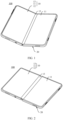
- FIG. 1 is a perspective view of a foldable display terminal 100 according to some embodiments of this application.
- the foldable display terminal 100 is a foldable display phone is used as an example for description.
- the foldable display terminal 100 includes a foldable display 10 and a support apparatus 20.
- FIG. 1 only shows an example of some components included in the foldable display terminal 100, and actual shapes, sizes, locations, and structures of these components are not limited by FIG. 1 .
- the foldable display 10 is configured to display images, videos, and the like.
- the foldable display 10 may be folded into a first part 11 and a second part 12.
- the foldable display 10 further includes a bendable part 13 between the first part 11 and the second part 12. At least the bendable part 13 of the foldable display 10 is made of a flexible material.
- the first part 11 and the second part 12 may be made of a flexible material, or a rigid material, or partially made of a rigid material and partially made of a flexible material. This is not specifically limited herein.
- the foldable display 10 may be an organic light-emitting diode (organic light-emitting diode, OLED) screen, a micro organic light-emitting diode (micro organic light-emitting diode) screen, a quantum dot light emitting diode (quantum dot light emitting diode, QLED) screen, a liquid crystal display (liquid crystal display, LCD), and the like.
- OLED organic light-emitting diode
- micro organic light-emitting diode micro organic light-emitting diode
- QLED quantum dot light emitting diode
- LCD liquid crystal display
- FIG. 2 is a schematic diagram of a structure of the foldable display terminal 100 shown in FIG. 1 when the foldable display 10 is in an unfolded state.
- the first part 11, the second part 12 and the bendable part 13 are coplanarly disposed and face the same direction. In this state, large-screen display can be implemented, so as to provide a user with more abundant information and better user experience.
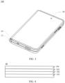
- FIG. 3 is a schematic diagram of a structure of the foldable display terminal 100 shown in FIG. 1 when the foldable display 10 is in a folded state.
- the bendable part 13 is in a bent state, and the first part 11 (not shown in FIG. 3 ) is opposite to the second part 12 (not shown in FIG. 3 ).
- the foldable display 10 is invisible to a user, and the support apparatus 20 is disposed outside the foldable display 10 for protection, to prevent the foldable display 10 from being scratched by hard objects.
- Such a foldable display phone is a phone with an inward foldable display.
- the first part 11 and the second part 12 may also depart from each other and be exposed.
- Such a foldable display phone is a phone with an outward foldable display.
- FIG. 4 is a sectional view of a foldable display 10 according to some embodiments of this application.
- a display 102 includes a substrate 101, a display 102, a polarizer 103, and a protective layer 104 that are sequentially laminated from inside to outside. Two adjacent layers may be connected by using an adhesive. It may be understood that FIG. 4 only shows an example of some components included in the foldable display 10, and actual shapes, sizes, locations and constructions of these components are not limited by FIG. 4 .
- the direction “outward” refers to a direction towards the outside of the foldable display terminal 100, and correspondingly, the direction “inward” refers to a direction towards the inside of the foldable display terminal 100.
- FIG. 5 is a front view of a support apparatus 20 in the foldable display terminal 100 shown in FIG. 1 .
- the support apparatus 20 includes a first housing 21, a second housing 22, and a rotating mechanism 23. It may be understood that FIG. 5 only shows an example of some components included in the support apparatus 20, and actual shapes, sizes, locations and constructions of these components are not limited by FIG. 5 .
- the first housing 21 is configured to fix and support the first part 11 of the foldable display 10 in FIG. 1 .
- the first housing 21 has a lamination surface M1
- the first housing 21 is configured to fix and support the first part 11 of the foldable display 10 in FIG. 1 through the lamination surface M1.
- the second housing 22 is configured to fix and support the second part 12 of the foldable display 10 in FIG. 1 .
- the second housing 22 has a lamination surface M2, and the second housing 22 is configured to fix and support the second part 12 of the foldable display 10 in FIG. 1 through the lamination surface M2.
- a first accommodating cavity (not shown in the figure) is formed inside the first housing 21.
- a second accommodating cavity (not shown in the figure) is formed inside the second housing 22.
- the first accommodating cavity and the second accommodating cavity are configured to accommodate electronic components such as a main board, a battery, a camera module, a speaker, and a receiver of the electronic device.
- FIG. 6 is an exploded view of the support apparatus 20 shown in FIG. 5 .
- the first housing 21 includes a first middle frame 211 and a first back cover 212.
- the lamination surface M1 is located on the first middle frame 211.
- the first back cover 212 is fixed to one side that is of the first middle frame 211 and that is away from the lamination surface M1.
- the first accommodating cavity is formed between the first middle frame 211 and the first back cover 212.
- the second housing 22 includes a second middle frame 221 and a second back cover 222.
- the lamination surface M2 is located on the second middle frame 221.
- the second back cover 222 is fixed to one side that is of the second middle frame 221 and that is away from the lamination surface M2.
- the second accommodating cavity is formed between the second middle frame 221 and the second back cover 222.
- the first middle frame 211 may be an integral structure, or may be formed by assembling a plurality of parts.
- the second middle frame 221 may be an integral structure, or may be formed by assembling a plurality of parts.
- the rotating mechanism 23 is connected between the first housing 21 and the second housing 22, and the first housing 21 and the second housing 22 are rotatably connected by using the rotating mechanism 23.
- the rotating mechanism 23 is connected between the first middle frame 211 of the first housing 21 and the second middle frame 221 of the second housing 22.
- the rotating mechanism 23 may be connected between the first back cover 212 of the first housing 21 and the second back cover 222 of the second housing 22.
- the rotating mechanism 23 includes a base 231, a first oscillating arm 232, and a second oscillating arm 233.
- an XYZ coordinate system is established for the rotating mechanism 23.
- an axial direction of the rotating mechanism 23 is defined as a Y-axis direction, that is, an extending direction of a rotation axis of the first housing 21 is the Y-axis direction;
- a thickness direction of the rotating mechanism 23 is defined as a Z-axis direction;
- a direction perpendicular to both the Y-axis direction and the Z-axis direction is defined as an X-axis direction.
- the coordinate system for the rotating mechanism 23 may be flexibly set based on actual needs. This is not specifically limited herein.
- the first housing 21 and the base 231 are rotatably connected and restrained by the first oscillating arm 232.
- the second housing 22 and the base 231 are connected and restrained by the second oscillating arm 233.
- a quantity of the first oscillating arm 232 may be one, two, or more.
- FIG. 5 and FIG. 6 only show an example in which two first oscillating arms 232 are provided, which should not be construed as a special limitation to this application.
- the two first oscillating arms 232 are spaced along a length direction of a rotation axis of the foldable display 10.
- a quantity of the second oscillating arm 233 may be the same as that of the first oscillating arm 232. In this way, stress equilibrium between the first housing 21 and the second housing 22 may be guaranteed during rotation.
- FIG. 7 is a schematic diagram of an assembly structure of a support apparatus 20 and a foldable display 10 in a foldable display terminal 100 according to some embodiments of this application.
- the foldable display 10 is fixedly connected to the first housing 21 and the second housing 22.
- the foldable display 10 is bonded to the first housing 21 and the second housing 22 by using an adhesive 30.
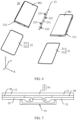
- FIG. 8 is a schematic diagram showing a folding process of the foldable display terminal 100 shown in FIG. 7 , where the foldable display 10 is bent correspondingly.
- FIG. 9 is a schematic diagram showing relative displacement among layers of the foldable display 10 during folding of the foldable display terminal 100 shown in FIG. 7 .
- FIG. 10 is a schematic diagram showing an unfolded state of the foldable display terminal 100 shown in FIG. 7 after repeated folding and unfolding.
- the bendable part 13 of the foldable display 10 is prone to reverse arching or depression, resulting in poor display.
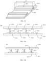
- FIG. 11a is a schematic diagram of a structure of a support apparatus 20 according to some other embodiments of this application
- FIG. 11b is a schematic diagram of an assembly structure of the support apparatus 20 shown in FIG. 11a and a foldable display 10.
- the support apparatus 20 in this embodiment includes a rotating mechanism 23, a first support portion 201, and a second support portion 202.
- the first support portion 201 is configured to support the first part 11 of the foldable display 10
- the second support portion 202 is configured to support the second part 12 of the foldable display 10.
- the first support portion 201 and the second support portion 202 are respectively disposed on two sides of the rotating mechanism 23.
- first support portion 201 and the second support portion 202 are respectively disposed on the two sides of the rotating mechanism 23 along the X-axis direction, and the second support portion 202 and the first support portion 201 may be folded or unfolded opposite to each other.
- the first support portion 201 includes a first support member 2011, a first elastic member 2013, and a first base plate 2012.
- the first base plate 2012 has a lamination surface M3, and the first base plate 2012 is configured to fix and support the first part 11 of the foldable display 10 in FIG. 1 through the lamination surface M3.
- the first base plate 2012 is a structure independent of the structure of the foldable display 10. It may be understood that, in other embodiments, the first base plate 2012 may also be constructed from a rigid substrate in the foldable display 10.
- the first base plate 2012 is formed into a rectangular plate-like structure, and a length direction of the first base plate 2012 is parallel to the Y-axis direction.
- the first base plate 2012 is a plastic member.
- the first base plate 2012 and the foldable display 10 may be connected by using an adhesive, but not limited thereto.
- the first support member 2011 may be formed into a rectangular plate-like structure. A length direction of the first support member 2011 is parallel to the Y-axis direction. The first support member 2011 is located on one side that is of the first base plate 2012 and that is away from the foldable display 10. The first support member 2011 is rotatably connected to the rotating mechanism 23.
- the structure of the first support member 2011 in this embodiment may be the same as the structure of the first housing 21 in the foldable display terminal 100 shown in FIG. 7 , and a manner in which the first support member 2011 is connected to the rotating mechanism 23 may be the same as the manner in which the first housing 21 in the foldable display terminal 100 is connected to the rotating mechanism 23 shown in FIG. 7 .
- FIG. 12 is a schematic diagram of a structure of a first support portion 201 in the support apparatus 20 shown in FIG. 1 1a .
- the foldable display terminal 100 is in an unfolded state.
- One end of the first elastic member 2013 is connected to the first support member 2011, and the other end of the first elastic member 2013 is connected to the first base plate 2012. It may be understood that the one end of the first elastic member 2013 may be directly connected to the first support member 2011, or may be indirectly connected to the first support member 2011 by using an intermediate medium.
- the other end of the second elastic member 2023 may be directly connected to the first base plate 2012, or may be indirectly connected to the first base plate 2012 by using an intermediate medium.
- the one end of the first elastic member 2013 may be connected to the first support member 2011 by using an adhesive, and the other end of the first elastic member 2013 may also be connected to the first base plate 2012 by using an adhesive.
- FIG. 13a is a schematic diagram showing a folding process of the foldable display terminal 100 shown in FIG. 11b
- FIG. 13b is a schematic diagram of a structure of a first support portion 201 in the foldable display terminal 100 shown in FIG. 13a .
- the first support member 2011 rotates along direction a with respect to the rotating mechanism 23, the bendable part 13 of the foldable display 10 is bent, and the first part 11 of the foldable display 10 tends to move in a direction away from the rotating mechanism 23 with respect to the first support portion 201.
- the first elastic member 2013 is elastically deformable to enable the first base plate 2012 to move in the direction close to or away from the rotating mechanism 23 with respect to the first support member 2011, the first part 11 of the foldable display 10 may move with the first base plate 2012 in the direction away from the rotating mechanism 23 with respect to the first support member 2011 during folding.
- the first elastic member 2013 is inclined in the direction away from the rotating mechanism 23, resulting in elastic deformation.
- the first support member 2011 rotates with respect to the rotating mechanism 23, the bendable part 13 of the foldable display 10 is unfolded, and the first part 11 of the foldable display 10 tends to move in a direction close to the rotating mechanism 23 with respect to the first support portion 201.
- the first elastic member 2013 is elastically deformable to enable the first base plate 2012 to move in the direction close to or away from the rotating mechanism 23 with respect to the first support member 2011, the first part 11 of the foldable display 10 may move with the first base plate 2012 in the direction close to the rotating mechanism 23 with respect to the first support member 2011 during unfolding, and meanwhile, the first elastic member 2013 recovers from the deformation.
- the elastically deformable first elastic member 2013 is disposed between the first base plate 2012 and the first support member 2011, so that relative movement between the first base plate 2012 and the first support member 2011 in a direction close to or away from the rotating mechanism 23 can be implemented when the foldable display terminal 100 is folded or unfolded, so as to provide a sliding space to the foldable display 10 when the foldable display terminal 100 is folded or unfolded, thereby reducing a stress on the foldable display 10 during folding, and reducing relative displacement among layers of the foldable display 10, so that deformation of a bendable part 13 of the foldable display 10 due to repeated folding or unfolding may be avoided, thereby prolonging the service life of the foldable display 10.
- FIG. 14 is a schematic diagram of an assembly structure of a first base plate 2012 and a first elastic member 2013 of the first support portion 201 shown in FIG. 12 .
- the first elastic member 2013 is formed into a strip, and a length direction of the first elastic member 2013 is parallel to a rotation axis of the first support member 2011. That is, the length direction of the first elastic member 2013 is parallel to the Y-axis direction.
- the first elastic member 2013 is prone to elastic deformation, and stress uniformity that is of the first base plate 2012 and that is in the Y-axis direction may be guaranteed.
- a quantity of the first elastic member 2013 may be small to reduce installation complexity.
- two ends, in the length direction, of the first elastic member 2013 extend respectively to be flush with two ends of the first base plate 2012.
- the two ends, in the length direction, of the first elastic member 2013 are a first end 2013a and a second end 2013b
- the two ends, in the Y-axis direction, of the first base plate 2012 are a third end 2012a and a fourth end 2012b.
- the first end 2013a of the first elastic member 2013 may extend to be flush with an end face of the third end 2012a of the first base plate 2012
- the second end 2013b of the first elastic member 2013 may extend to be flush with an end face of the fourth end 2012b of the first base plate 2012. In this way, the stress uniformity that is of the first base plate 2012 and that is in the Y-axis direction may be further improved.
- a quantity of the first elastic member 2013 is more than one, and each first elastic member 2013 is connected between the first base plate 2012 and the first support member 2011.
- the plurality of first elastic members 2013 are spaced along a first direction, where the first direction is perpendicular to the rotation axis of the first support member 2011.
- the first direction is a width direction of the first base plate 2012, that is, the X-axis direction in FIG. 14 .
- the plurality of first elastic members 2013 are spaced in the width direction of the first base plate 2012. In this way, stress uniformity that is of the first base plate 2012 and that is in the first direction may be guaranteed.
- the support apparatus 20 further includes a first stop portion 2014, the first stop portion 2014 is disposed on a surface that is of the first base plate 2012 and that faces the first support member 2011, the first elastic member 2013 is connected to the first stop portion 2014, and at least a part of the first stop portion 2014 is located on one side that is of the first elastic member 2013 and that is close to the rotating mechanism 23.
- the first stop portion 2014 is wholly located on the side that is of the first elastic member 2013 and that is close to the rotating mechanism 23.
- a part of the first stop portion 2014 may be located on the side that is of the first elastic member 2013 and that is close to the rotating mechanism 23, and another part of the first stop portion 2014 may be located on the side that is of the first elastic member 2013 and that is away from the rotating mechanism 23, provided that at least a part of the first stop portion 2014 is located on the side that is of the first elastic member 2013 and that is close to the rotating mechanism 23.
- one end that is of the first stop portion 2014 and that is close to the first elastic member 2013 is abutted against and cooperates with a side wall that is of the first elastic member 2013 and that is close to the rotating mechanism 23 to limit an inclination angle and a deformation amount of the first elastic member 2013, so that the deformation amount of the first elastic member 2013 may be adjusted by the first stop portion 2014 to avoid excessive deformation of the first elastic member 2013, and improve reliability of the support apparatus 20.
- Dashed lines in FIG. 13b show a schematic diagram of a state in which the side wall that is of the first elastic member 2013 and that is close to the rotating mechanism 23 is not stopped by the first stop portion 2014.
- the first elastic member 2013 is connected to one end that is of the first stop portion 2014 and that is away from the rotating mechanism 23.
- the first stop portion 2014 and the first elastic member 2013 When the foldable display terminal 100 is in an unfolded state, the first stop portion 2014 and the first elastic member 2013 generally form a "7" shape.
- the structure is simple, and processing is easy.
- a stop effect of the first stop portion 2014 on the first elastic member 2013 can be easily achieved.
- the first stop portion 2014 is formed into a strip, the length direction of the first stop portion 2014 is consistent with the length direction of the first elastic member 2013, and a length L1 of the first stop portion 2014 is equal to a length L2 of the first elastic member 2013. In this way, the stop effect of the first stop portion 2014 may be improved, and a quantity of the first stop portion 2014 may be small during assembly to reduce installation complexity.
- a thickness d1 of the first stop portion 2014 is less than a spacing d2 between the first base plate 2012 and the first support member 2011. In this way, referring to FIG. 12 and FIG. 13a , a side surface that is of the first stop portion 2014 and that faces the first support member 2011 is spaced apart from the first support member 2011. In this way, the deformation amount of the first elastic member 2013 may be guaranteed while the stop effect of the first stop portion 2014 is guaranteed.
- an elastic modulus of the first stop portion 2014 may be higher than that of the first elastic member 2013.
- a greater elastic modulus indicates higher stiffness of a material, that is, less elastic deformation of the material under a stress.
- the first stop portion 2014 may be a plastic member
- the first elastic member 2013 may be a rubber member or a silicone member.
- the first elastic member 2013 and the first stop portion 2014 are in an integrated structure. That is, the first elastic member 2013 and the first stop portion 2014 are integrally formed.
- the first elastic member 2013 and the first stop portion 2014 may be integrally injection-molded.
- the first elastic member 2013 and the first stop portion 2014 may be integrally formed by using a double-shot molding process. Therefore, the processing technology for the first support portion 201 may be simplified to improve the processing efficiency.
- the first stop portion 2014 and the first base plate 2012 are in an integrated structure. That is, the first stop portion 2014 and the first base plate 2012 are integrally formed.
- the first elastic member 2013 and the first stop portion 2014 may be integrally injection-molded. Therefore, the processing technology for the first support portion 201 may be further simplified to improve the processing efficiency.
- the first stop portion 2014 and the first base plate 2012 may be connected by using an adhesive, but not limited thereto.
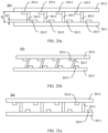
- FIG. 15a is a schematic diagram of a structure of a first support portion 201 according to some other embodiments of this application.
- the first support portion 201 in this embodiment differs from the first support portion 201 shown in FIG. 12 in that the first stop portion 2014 in this embodiment is spaced apart from the first elastic member 2013.
- a spacing d3 between the first stop portion 2014 and the first elastic member 2013 is less than a spacing d2 between the first base plate 2012 and the first support member 2011. That is, the spacing d3 between the first stop portion 2014 and the first elastic member 2013 is less than a thickness of the first elastic member 2013.
- FIG. 15b is a schematic diagram of a structure of the first support portion 201 shown in FIG.
- the first stop portion 2014 may also be abutted against the side wall that is of the first elastic member 2013 and that is close to the rotating mechanism 23 to limit an inclination angle and a deformation amount of the first elastic member 2013, so that the deformation amount of the first elastic member 2013 may be adjusted by the first stop portion 2014 to avoid excessive deformation of the first elastic member 2013, thereby improving the reliability of the support apparatus 20.
- FIG. 16a is a schematic diagram of a structure of a first support portion 201 according to some other embodiments of this application.
- the first support portion 201 in this embodiment differs from the first support portion 201 shown in FIG. 12 in that a part of the first stop portion 2014 in this embodiment is located on the side that is of the first elastic member 2013 and that is close to the rotating mechanism 23, and another part of the first stop portion 2014 is located on the side that is of the first elastic member 2013 and that is away from the rotating mechanism 23.
- the first elastic member 2013 and the first stop portion 2014 when the foldable display terminal 100 is in an unfolded state, the first elastic member 2013 and the first stop portion 2014 generally form a "T" shape.
- FIG. 16b is a schematic diagram of a structure of the first support portion 201 shown in FIG. 16a when the foldable display terminal 100 is being folded or in a folded state.
- the first stop portion 2014 may also be abutted against the side wall that is of the first elastic member 2013 and that is close to the rotating mechanism 23 to limit an inclination angle and a deformation amount of the first elastic member 2013, so that the deformation amount of the first elastic member 2013 may be adjusted by the first stop portion 2014 to avoid excessive deformation of the first elastic member 2013, thereby improving the reliability of the support apparatus 20.
- FIG. 17a is a schematic diagram of a structure of a first support portion 201 according to some other embodiments of this application.
- the first support portion 201 in this embodiment differs from the first support portion 201 shown in FIG. 12 in that the first support portion 201 in this embodiment further includes a second stop portion 2015 in addition to the first base plate 2012, the first elastic member 2013, the first support member 2011, and the first stop portion 2014 of the first support portion 201 shown in FIG. 12 .
- the second stop portion 2015 is disposed on a side surface that is of the first support member 2011 and that faces the first base plate 2012, and at least a part of the second stop portion 2015 is located on one side that is of the first elastic member 2013 and that is away from the rotating mechanism 23.
- the second stop portion 2015 is wholly located on the side that is of the first elastic member 2013 and that is away from the rotating mechanism 23. It may be understood that, in other embodiments, a part of the second stop portion 2015 may be located on the side that is of the first elastic member 2013 and that is away from the rotating mechanism 23, and another part of the second stop portion 2015 may be located on the side that is of the first elastic member 2013 and that is close to the rotating mechanism 23,
- FIG. 17b is a schematic diagram of a structure of the first support portion 201 shown in FIG. 17a when the foldable display terminal 100 is being folded or in a folded state.
- one end that is of the first stop portion 2014 and that is close to the first elastic member 2013 is abutted against a side wall that is of the first elastic member 2013 and that is close to the rotating mechanism 23, and one end that is of the second stop portion 2015 and that is close to the first elastic member 2013 is abutted against a side wall that is of the first elastic member 2013 and that is away from the rotating mechanism 23.
- an inclination angle and a deformation amount of the first elastic member 2013 may be limited by the first stop portion 2014 and the second stop portion 2015, so that the deformation amount of the first elastic member 2013 may be adjusted to avoid excessive deformation of the first elastic member 2013, thereby improving the reliability of the support apparatus 20.
- Dashed lines in FIG. 17b show a schematic diagram of a state in which the side wall that is of the first elastic member 2013 and that is away from the rotating mechanism 23 is not stopped by the second stop portion 2015.
- the first elastic member 2013 may be connected to one end that is of the second stop portion 2015 and that is close to the rotating mechanism 23.
- the first stop portion 2014, the second stop portion 2015, and the first elastic member 2013 generally form a "Z" shape.
- the structure is simple, and processing is easy.
- a stop effect of the first stop portion 2014 and the second stop portion 2015 on the first elastic member 2013 can be easily achieved.
- FIG. 18 is a schematic diagram of an assembly structure of the first base plate 2012, the first elastic member 2013, the first stop portion 2014, and the second stop portion 2015 shown in FIG. 17a .
- the second stop portion 2015 is formed into a strip, the length direction of the second stop portion 2015 is consistent with the length direction of the first elastic member 2013, and a length L3 of the second stop portion 2015 is equal to the length L1 of the first elastic member 2013. In this way, the stop effect of the second stop portion 2015 may be improved, and a quantity of the second stop portion 2015 may be small during assembly to reduce installation complexity.
- a thickness d4 of the second stop portion 2015 is less than the spacing d2 between the first base plate 2012 and the first support member 2011. Specifically, a side surface that is of the second stop portion 2015 and that faces the first base plate 2012 is spaced apart from the first base plate 2012. In this way, the deformation amount of the first elastic member 2013 may be guaranteed while the stop effect of the second stop portion 2015 is guaranteed.
- FIG. 19a is a schematic diagram of a structure of a first support portion 201 according to some other embodiments of this application.
- the first support portion 201 in this embodiment differs from the first support portion 201 shown in FIG. 17a in that a part of the second stop portion 2015 in this embodiment is located on the side that is of the first elastic member 2013 and that is close to the rotating mechanism 23, and another part of the second stop portion 2015 is located on the side that is of the first elastic member 2013 and that is away from the rotating mechanism 23.
- the first elastic member 2013 and the second stop portion 2015 When the foldable display terminal 100 is in an unfolded state, the first elastic member 2013 and the second stop portion 2015 generally form a "T" shape.
- FIG. 19b is a schematic diagram of a structure of the first support portion 201 shown in FIG. 19a when the foldable display terminal 100 is being folded or in a folded state.
- one end that is of the first stop portion 2014 and that is close to the first elastic member 2013 is abutted against a side wall that is of the first elastic member 2013 and that is close to the rotating mechanism 23, and one end that is of the second stop portion 2015 and that is close to the first elastic member 2013 is abutted against a side wall that is of the first elastic member 2013 and that is away from the rotating mechanism 23.
- an inclination angle and a deformation amount of the first elastic member 2013 may also be limited by the first stop portion 2014 and the second stop portion 2015, so that the deformation amount of the first elastic member 2013 may be adjusted to avoid excessive deformation of the first elastic member 2013, thereby improving the reliability of the support apparatus 20.
- Dashed lines in FIG. 19b show a schematic diagram of a state in which the side wall that is of the first elastic member 2013 and that is away from the rotating mechanism 23 is not stopped by the second stop portion 2015.
- FIG. 20a is a schematic diagram of a structure of a first support portion 201 according to some other embodiments of this application.
- the first support portion 201 in this embodiment differs from the first support portion 201 shown in FIG. 17a in that the second stop portion 2015 in the first support portion 201 in this embodiment is spaced apart from the first elastic member 2013.
- a spacing d5 between the second stop portion 2015 and the first elastic member 2013 is less than the spacing d2 between the first base plate 2012 and the first support member 2011. That is, the spacing d5 between the second stop portion 2015 and the first elastic member 2013 is less than the thickness of the first elastic member 2013.
- FIG. 20b is a schematic diagram of a structure of the first support portion 201 shown in FIG. 20a when the foldable display terminal 100 is being folded or in a folded state.
- one end that is of the first stop portion 2014 and that is close to the first elastic member 2013 is abutted against a side wall that is of the first elastic member 2013 and that is close to the rotating mechanism 23, and one end that is of the second stop portion 2015 and that is close to the first elastic member 2013 is abutted against a side wall that is of the first elastic member 2013 and that is away from the rotating mechanism 23.
- an inclination angle and a deformation amount of the first elastic member 2013 may also be limited by the first stop portion 2014 and the second stop portion 2015, so that the deformation amount of the first elastic member 2013 may be adjusted to avoid excessive deformation of the first elastic member 2013, thereby improving the reliability of the support apparatus 20.
- Dashed lines in FIG. 20b show a schematic diagram of a state in which the side wall that is of the first elastic member 2013 and that is away from the rotating mechanism 23 is not stopped by the second stop portion 2015.
- FIG. 21a is a schematic diagram of a structure of a first support portion 201 according to some other embodiments of this application
- FIG. 21b is a schematic diagram of a structure of the first support portion 201 shown in FIG. 21a when the foldable display terminal 100 is being folded or in a folded state.
- the first support portion 201 in this embodiment differs from the first support portion 201 shown in FIG. 20a in that the first stop portion 2014 in the first support portion 201 in this embodiment is spaced apart from the first elastic member 2013.
- one end that is of the first stop portion 2014 and that is close to the first elastic member 2013 is abutted against a side wall that is of the first elastic member 2013 and that is close to the rotating mechanism 23, and one end that is of the second stop portion 2015 and that is close to the first elastic member 2013 is abutted against a side wall that is of the first elastic member 2013 and that is away from the rotating mechanism 23. Therefore, an inclination angle and a deformation amount of the first elastic member 2013 may be limited by the first stop portion 2014 and the second stop portion 2015, so that the deformation amount of the first elastic member 2013 may be adjusted to avoid excessive deformation of the first elastic member 2013, thereby improving the reliability of the support apparatus 20.
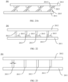
- FIG. 22 is a schematic diagram of a structure of a first support portion 201 according to some other embodiments of this application.
- the first support portion 201 in this embodiment differs from the first support portion 201 shown in FIG. 17a in that the first support portion 201 in this embodiment includes only the first base plate 2012, the first elastic member 2013, the first support member 2011, and the second stop portion 2015 of the first support portion 201 shown in FIG. 17a , but does not include the first stop portion 2014.
- the second stop portion 2015 may be abutted against the side wall that is of the first elastic member 2013 and that is away from the rotating mechanism 23, so that the deformation amount of the first elastic member 2013 may be adjusted by the second stop portion 2015 to avoid excessive deformation of the first elastic member 2013, thereby improving the reliability of the support apparatus 20.
- the second stop portion 2015 is connected to one end that is of the first elastic member 2013 and that is away from the rotating mechanism 23. It may be understood that, in other embodiments, the second stop portion 2015 may also be spaced apart from the first elastic member 2013.
- FIG. 23 is a schematic diagram of a structure of a first support portion 201 according to some other embodiments of this application.
- the first support portion 201 in this embodiment differs from the first support portion 201 shown in FIG. 12 in that the first support portion 201 in this embodiment includes only the first base plate 2012, the first elastic member 2013, and the first support member 2011 of the first support portion 201 shown in FIG. 12 , but does not include the first stop portion 2014.
- FIG. 24 is a schematic diagram of a structure of a first support portion 201 according to some other embodiments of this application.
- the width w of the first elastic member 2013 gradually increases in a direction from the first base plate 2012 to the first support member 2011.
- the structure of the second support portion 202 is the same as that of the first support portion 201, and the second support portion 202 and the first support portion 201 are symmetrically disposed on two sides of the rotating mechanism 23.
- the second support portion 202 includes a second support member 2021, a second elastic member 2023, and a second base plate 2022.
- the second support member 2021 is laminated with the second base plate 2022.
- the second elastic member 2023 is connected between the second support member 2021 and the second base plate 2022, and the second elastic member 2023 is elastically deformable to enable the second base plate 2022 and the second support member 2021 to move relative to each other.
- FIG. 25 is a schematic diagram of a structure of a support apparatus 20 according to some other embodiments of this application.
- the second support portion 202 includes only the second support member 2021, but does not include the second elastic member 2023 and the second base plate 2022 in the foregoing embodiments.
- the second part 12 of the foldable display 10 is directly bonded to the second support member 2021 by using an adhesive 30.
Landscapes
- Engineering & Computer Science (AREA)
- Signal Processing (AREA)
- Computer Hardware Design (AREA)
- Theoretical Computer Science (AREA)
- Human Computer Interaction (AREA)
- Physics & Mathematics (AREA)
- General Engineering & Computer Science (AREA)
- General Physics & Mathematics (AREA)
- Devices For Indicating Variable Information By Combining Individual Elements (AREA)
Abstract
Description
- This application claims priority to
Chinese Patent Application No. 202111250570.2, filed with the China National Intellectual Property Administration on October 26, 2021 - This application relates to the field of foldable display terminal technologies, and in particular, to a support apparatus and a foldable display terminal.
- As fast-growing mobile terminal devices, terminals such as smartphones are fully reflected in the latest technological innovations and technological iterations. Currently, when people are pursuing portability of terminals, they also hope that displays of the terminals are large enough. Therefore foldable display terminals emerge.
- However, when a foldable display terminal is folded or unfolded, a bending stress is applied to a bendable or foldable display. During repeated folding and unfolding, a bendable part of the foldable display may be easily damaged due to repeated compression and stretching.
- This application provides a support apparatus and a foldable display terminal, to reduce a stress on a foldable display during folding, so as to prolong the service life of the foldable display terminal.
- To achieve the foregoing objective, the following technical solutions are used in embodiments of this application:
- According to a first aspect, this application provides a support apparatus, including: a rotating mechanism, a first support portion, and a second support portion, where the first support portion includes a first support member, a first elastic member, and a first base plate, the first elastic member is connected between the first base plate and the first support member, and the first elastic member is elastically deformable to enable the first base plate to move in a direction close to or away from the rotating mechanism with respect to the first support member; and the second support portion and the first support portion are respectively disposed on two sides of the rotating mechanism, and the second support portion and the first support portion may be folded or unfolded opposite to each other.
- According to the support apparatus provided in this application, the elastically deformable first elastic member is disposed between the first base plate and the first support member, so that relative movement between the first base plate and the first support member in a direction close to or away from the rotating mechanism can be implemented when the foldable display terminal is folded or unfolded, so as to provide a sliding space to the foldable display when the foldable display terminal is folded or unfolded. This reduces a stress on the foldable display during folding, and reduces relative displacement among layers of the foldable display, so that deformation of a bendable part of the foldable display due to repeated folding or unfolding may be avoided, thereby prolonging the service life of the foldable display.
- In a possible design of the first aspect, the first elastic member is formed into a strip, and a length direction of the first elastic member is parallel to a rotation axis of the first support member. In this way, during folding of the foldable display terminal, the first elastic member is prone to elastic deformation, and stress uniformity of the first base plate may be guaranteed. In addition, a quantity of the first elastic member may be small to reduce installation complexity.
- In a possible design of the first aspect, two ends, in a length direction, of the first elastic member extend respectively to be flush with two ends of the first base plate. In this way, the stress uniformity of the first base plate may be further improved.
- In a possible design of the first aspect, a quantity of the first elastic member is more than one, each first elastic member is connected to the first base plate, and the plurality of first elastic members are spaced in a first direction, where the first direction is perpendicular to an extending direction of the rotation axis of the first support member. In this way, stress uniformity that is of the first base plate and that is in the first direction may be guaranteed.
- In a possible design of the first aspect, the first support portion further includes: a first stop portion, where the first stop portion is disposed on a side surface that is of the first base plate and that faces the first support member, and at least a part of the first stop portion is located on one side that is of the first elastic member and that is close to the rotating mechanism. In this way, during folding of the foldable display terminal, one end that is of the first stop portion and that is close to the first elastic member is abutted against and cooperates with a side wall that is of the first elastic member and that is close to the rotating mechanism, to limit an inclination angle and a deformation amount of the first elastic member, so that the deformation amount of the first elastic member may be adjusted by the first stop portion to avoid excessive deformation of the first elastic member, thereby improving reliability of the support apparatus.
- In a possible design of the first aspect, the first elastic member is connected to one end that is of the first stop portion and that is away from the rotating mechanism. The structure is simple, and processing is easy. In addition, during folding of the foldable display terminal, a stop effect of the first stop portion on the first elastic member can be easily achieved.
- In a possible design of the first aspect, the first elastic member is spaced apart from the first stop portion. A spacing between the first stop portion and the first elastic member is less than a spacing between the first base plate and the first support member. That is, the spacing between the first stop portion and the first elastic member is less than a thickness of the first elastic member. In this way, during folding of the foldable display terminal, the first stop portion may also be abutted against the side wall that is of the first elastic member and that is close to the rotating mechanism, to limit an inclination angle and a deformation amount of the first elastic member, so that the deformation amount of the first elastic member may be adjusted by the first stop portion to avoid excessive deformation of the first elastic member, thereby improving reliability of the support apparatus.
- In a possible design of the first aspect, the first elastic member and the first stop portion are in an integrated structure. Therefore, the processing technology for the first support portion may be simplified to improve the processing efficiency.
- In a possible design of the first aspect, the first stop portion and the first base plate are in an integrated structure. Therefore, the processing technology for the first support portion may be simplified to improve the processing efficiency.
- In a possible design of the first aspect, an elastic modulus of the first stop portion is greater than that of the first elastic member. In this way, the stop effect of the first stop portion may be improved.
- In a possible design of the first aspect, the support apparatus further includes a second stop portion, the second stop portion is connected to a side surface that is of the first support member and that faces the first base plate, and at least a part of the second stop portion is located on one side that is of the first elastic member and that is away from the rotating mechanism. During folding of the foldable display terminal, one end that is of the first stop portion and that is close to the first elastic member is abutted against a side wall that is of the first elastic member and that is close to the rotating mechanism, and one end that is of the second stop portion and that is close to the first elastic member is abutted against a side wall that is of the first elastic member and that is away from the rotating mechanism. Therefore, an inclination angle and a deformation amount of the first elastic member may be limited by the first stop portion and the second stop portion, so that the deformation amount of the first elastic member may be adjusted to avoid excessive deformation of the first elastic member, thereby improving the reliability of the support apparatus.
- In a possible design of the first aspect, the first elastic member is connected to one end that is of the second stop portion and that is close to the rotating mechanism. The first stop portion, the second stop portion and the first elastic member generally form a "Z" shape. The structure is simple, and processing is easy. In addition, a stop effect of the first stop portion and the second stop portion on the first elastic member can be easily achieved.
- In a possible design of the first aspect, the first elastic member is spaced apart from the second stop portion.
- In a possible design of the first aspect, the first elastic member and the second stop portion are in an integrated structure. Therefore, the processing technology for the first support portion may be simplified to improve the processing efficiency.
- In a possible design of the first aspect, a width of the first elastic member remains unchanged or gradually decreases in a direction from the first base plate to the first support member. The structure is simple, and processing is easy.
- In a possible design of the first aspect, the first elastic member is a rubber member or a silicone member.
- In a possible design of the first aspect, the second support portion includes: a second support member, a second base plate, and a second elastic member, where the second support member is rotatably connected to the rotating mechanism; the second base plate is laminated with the second support member; and the second elastic member is connected between the first base plate and the first support member, and the second elastic member is elastically deformable to enable the second base plate and the second support member to move relative to each other. In this way, the elastically deformable second elastic member is disposed between the second base plate and the second support member, so that when the foldable display terminal is folded or unfolded, the foldable display can be driven by the second base plate to slide with respect to the second support member, thereby reducing a stress on the foldable display during folding or unfolding, and reducing relative displacement among layers of the foldable display. Therefore, deformation of a bendable part of the foldable display due to repeated folding or unfolding may be avoided, which prolongs the service life of the foldable display.
- In a possible design of the first aspect, the second support portion includes a second support member, and the second support member is rotatably connected to the rotating mechanism.
- According to a second aspect, this application provides a foldable display terminal, including: a foldable display and a support apparatus, where the foldable display includes a first part, a second part, and a bendable part between the first part and the second part; and the support apparatus is the support apparatus in any one of the foregoing technical solutions, the first support portion is configured to support the first part and the second support portion is configured to support the second part.
- Because the foldable display terminal provided in embodiments of this application includes the support apparatus in the foregoing technical solutions, both the foldable display terminal and the support apparatus can resolve the same technical problem and achieve the same effect.
-
-
FIG. 1 is a perspective view of a foldable display terminal according to some embodiments of this application; -
FIG. 2 is a schematic diagram of a structure of the foldable display terminal shown inFIG. 1 in an unfolded state; -
FIG. 3 is a schematic diagram of a structure of the foldable display terminal shown inFIG. 1 in a folded state; -
FIG. 4 is a sectional view of a foldable display in the foldable display terminal shown inFIG. 1 ; -
FIG. 5 is a front view of a support apparatus in the foldable display terminal shown inFIG. 1 ; -
FIG. 6 is an exploded view of the support apparatus shown inFIG. 5 ; -
FIG. 7 is an assembly diagram of the support apparatus shown inFIG. 5 and the foldable display; -
FIG. 8 is a schematic diagram showing a folding process of the foldable display terminal shown inFIG. 7 ; -
FIG. 9 is a schematic diagram showing relative displacement among layers of the foldable display during folding of the foldable display terminal shown inFIG. 7 ; -
FIG. 10 is a schematic diagram showing an unfolded state of the foldable display terminal shown inFIG. 7 after repeated folding and unfolding; -
FIG. 1 1a is a schematic diagram of a structure of a support apparatus according to some other embodiments of this application; -
FIG. 11b is a schematic diagram of an assembly structure of the support apparatus shown inFIG. 11a and a foldable display; -
FIG. 12 is a schematic diagram of a structure of a first support portion in the support apparatus shown inFIG. 11a ; -
FIG. 13a is a schematic diagram of a structure during folding of the foldable display terminal shown inFIG. 11b ; -
FIG. 13b is a schematic diagram of a structure of a first support portion in the foldable display terminal shown inFIG. 13 a; -
FIG. 14 is a schematic diagram of an assembly structure of a first base plate and a first elastic member of the first support portion shown inFIG. 12 ; -
FIG. 15a is a schematic diagram of a structure of a first support portion according to some other embodiments of this application; -
FIG. 15b is a schematic diagram of a structure of the first support portion shown inFIG. 15a when the foldable display terminal is being folding or in a folded state; -
FIG. 16a is a schematic diagram of a structure of a first support portion according to some other embodiments of this application; -
FIG. 16b is a schematic diagram of a structure of the first support portion shown inFIG. 16a when the foldable display terminal is being folding or in a folded state; -
FIG. 17a is a schematic diagram of a structure of a first support portion according to some other embodiments of this application; -
FIG. 17b is a schematic diagram of a structure of the first support portion shown inFIG. 17a when the foldable display terminal is being folding or in a folded state; -
FIG. 18 is a schematic diagram of an assembly structure of the first base plate, the first elastic member, the first stop portion, and the second stop portion shown inFIG. 17a ; -
FIG. 19a is a schematic diagram of a structure of a first support portion according to some other embodiments of this application; -
FIG. 19b is a schematic diagram of a structure of the first support portion shown inFIG. 19a when the foldable display terminal is being folding or in a folded state; -
FIG. 20a is a schematic diagram of a structure of a first support portion according to some other embodiments of this application; -
FIG. 20b is a schematic diagram of a structure of the first support portion shown inFIG. 20a when the foldable display terminal is being folding or in a folded state; -
FIG. 21a is a schematic diagram of a structure of a first support portion according to some other embodiments of this application; -
FIG. 21b is a schematic diagram of a structure of the first support portion shown inFIG. 21a when the foldable display terminal is being folding or in a folded state; -
FIG. 22 is a schematic diagram of a structure of a first support portion according to some other embodiments of this application; -
FIG. 23 is a schematic diagram of a structure of a first support portion according to some other embodiments of this application; -
FIG. 24 is a schematic diagram of a structure of a first support portion according to some other embodiments of this application; and -
FIG. 25 is a schematic diagram of a structure of a support apparatus according to some other embodiments of this application. -
- 100. Foldable display terminal;
- 10. Foldable display; 11. First part; 12. Second part; 13. Bendable part; 101. Substrate; 102. Display; 103. Polarizer; 104. Protective layer;
- 20. Support apparatus; 21. First housing; 211. First middle frame; 212. First back cover; 22. Second housing; 221. Second middle frame; 222. Second back cover;
- 201. First support portion; 2011. First support member; 2012. First base plate; 2012a. Third end; 2012b. Fourth end; 2013. First elastic member; 2013a. First end; 2013b. Second end; 2014. First stop portion; 2015. Second stop portion;
- 202. Second support portion; 2021. Second support member; 2022. Second base plate; 2023. Second elastic member;
- 23. Rotating mechanism; 231. Base; 232. First oscillating arm; 233. Second oscillating arm;
- 30. Adhesive.
- In embodiments of this application, the terms "first", "second", "third" and "fourth" are used for descriptive purposes only, and cannot be construed as indicating or implying relative importance or implicitly indicating a quantity of indicated technical features. Therefore, features defined with "first", "second", "third" and "fourth" may explicitly or implicitly include one or more of the features.
- In embodiments of this application, the term "including", "containing" or any other variant thereof is intended to cover non-exclusive inclusion, so that a process, method, article or apparatus including a series of elements includes not only those elements, but also other elements not explicitly listed, or elements inherent to such a process, method, article or apparatus. Without further limitation, the element defined by the sentence "including a... " does not exclude that other identical elements are also present in the process, method, article or apparatus including the element.
- In embodiments of this application, the term "and/or" is only used to describe an association relationship between associated objects, and indicates that three relationships may exist. For example, A and/or B may indicate the following: Only A exists, both A and B exist, and only B exists. In addition, the symbol "/" used herein generally represents an "or" relationship between associated objects.
- This application provides a foldable display terminal, and the foldable display terminal is a type of terminal device with a foldable display. Specifically, the foldable display terminal includes, but is not limited to, a mobile phone. That is, the foldable display terminal may also be another type of terminal device with a foldable display.
- Referring to
FIG. 1, FIG. 1 is a perspective view of afoldable display terminal 100 according to some embodiments of this application. In this embodiment, that thefoldable display terminal 100 is a foldable display phone is used as an example for description. Thefoldable display terminal 100 includes afoldable display 10 and asupport apparatus 20. - It may be understood that
FIG. 1 only shows an example of some components included in thefoldable display terminal 100, and actual shapes, sizes, locations, and structures of these components are not limited byFIG. 1 . - The
foldable display 10 is configured to display images, videos, and the like. Thefoldable display 10 may be folded into afirst part 11 and asecond part 12. Thefoldable display 10 further includes abendable part 13 between thefirst part 11 and thesecond part 12. At least thebendable part 13 of thefoldable display 10 is made of a flexible material. Thefirst part 11 and thesecond part 12 may be made of a flexible material, or a rigid material, or partially made of a rigid material and partially made of a flexible material. This is not specifically limited herein. - Specifically, the
foldable display 10 may be an organic light-emitting diode (organic light-emitting diode, OLED) screen, a micro organic light-emitting diode (micro organic light-emitting diode) screen, a quantum dot light emitting diode (quantum dot light emitting diode, QLED) screen, a liquid crystal display (liquid crystal display, LCD), and the like. - The
foldable display 10 can be folded between an unfolded state and a folded state. Referring toFIG. 2, FIG. 2 is a schematic diagram of a structure of thefoldable display terminal 100 shown inFIG. 1 when thefoldable display 10 is in an unfolded state. When thefoldable display 10 is in the unfolded state, thefirst part 11, thesecond part 12 and thebendable part 13 are coplanarly disposed and face the same direction. In this state, large-screen display can be implemented, so as to provide a user with more abundant information and better user experience. - Referring to
FIG. 3, FIG. 3 is a schematic diagram of a structure of thefoldable display terminal 100 shown inFIG. 1 when thefoldable display 10 is in a folded state. When thefoldable display 10 is in the folded state, thebendable part 13 is in a bent state, and the first part 11 (not shown inFIG. 3 ) is opposite to the second part 12 (not shown inFIG. 3 ). Thefoldable display 10 is invisible to a user, and thesupport apparatus 20 is disposed outside thefoldable display 10 for protection, to prevent thefoldable display 10 from being scratched by hard objects. Such a foldable display phone is a phone with an inward foldable display. In other embodiments, when thefoldable display 10 is in a folded state, thefirst part 11 and thesecond part 12 may also depart from each other and be exposed. Such a foldable display phone is a phone with an outward foldable display. - In some embodiments, referring to
FIG. 4, FIG. 4 is a sectional view of afoldable display 10 according to some embodiments of this application. Adisplay 102 includes asubstrate 101, adisplay 102, apolarizer 103, and aprotective layer 104 that are sequentially laminated from inside to outside. Two adjacent layers may be connected by using an adhesive. It may be understood thatFIG. 4 only shows an example of some components included in thefoldable display 10, and actual shapes, sizes, locations and constructions of these components are not limited byFIG. 4 . - It should be noted that, in this application, the direction "outward" refers to a direction towards the outside of the
foldable display terminal 100, and correspondingly, the direction "inward" refers to a direction towards the inside of thefoldable display terminal 100. - The
support apparatus 20 is configured to support thefoldable display 10 and allow thefoldable display 10 to be folded between the unfolded state and the folded state. Referring toFIG. 5, FIG. 5 is a front view of asupport apparatus 20 in thefoldable display terminal 100 shown inFIG. 1 . In this embodiment, thesupport apparatus 20 includes afirst housing 21, asecond housing 22, and arotating mechanism 23. It may be understood thatFIG. 5 only shows an example of some components included in thesupport apparatus 20, and actual shapes, sizes, locations and constructions of these components are not limited byFIG. 5 . - The
first housing 21 is configured to fix and support thefirst part 11 of thefoldable display 10 inFIG. 1 . Specifically, thefirst housing 21 has a lamination surface M1, and thefirst housing 21 is configured to fix and support thefirst part 11 of thefoldable display 10 inFIG. 1 through the lamination surface M1. - The
second housing 22 is configured to fix and support thesecond part 12 of thefoldable display 10 inFIG. 1 . Specifically, thesecond housing 22 has a lamination surface M2, and thesecond housing 22 is configured to fix and support thesecond part 12 of thefoldable display 10 inFIG. 1 through the lamination surface M2. - A first accommodating cavity (not shown in the figure) is formed inside the
first housing 21. A second accommodating cavity (not shown in the figure) is formed inside thesecond housing 22. The first accommodating cavity and the second accommodating cavity are configured to accommodate electronic components such as a main board, a battery, a camera module, a speaker, and a receiver of the electronic device. - In some embodiments, referring to
FIG. 6, FIG. 6 is an exploded view of thesupport apparatus 20 shown inFIG. 5 . Thefirst housing 21 includes a firstmiddle frame 211 and afirst back cover 212. The lamination surface M1 is located on the firstmiddle frame 211. Thefirst back cover 212 is fixed to one side that is of the firstmiddle frame 211 and that is away from the lamination surface M1. The first accommodating cavity is formed between the firstmiddle frame 211 and thefirst back cover 212. - The
second housing 22 includes a secondmiddle frame 221 and asecond back cover 222. The lamination surface M2 is located on the secondmiddle frame 221. Thesecond back cover 222 is fixed to one side that is of the secondmiddle frame 221 and that is away from the lamination surface M2. The second accommodating cavity is formed between the secondmiddle frame 221 and thesecond back cover 222. - The first
middle frame 211 may be an integral structure, or may be formed by assembling a plurality of parts. Similarly, the secondmiddle frame 221 may be an integral structure, or may be formed by assembling a plurality of parts. - The
rotating mechanism 23 is connected between thefirst housing 21 and thesecond housing 22, and thefirst housing 21 and thesecond housing 22 are rotatably connected by using therotating mechanism 23. In some embodiments, the rotatingmechanism 23 is connected between the firstmiddle frame 211 of thefirst housing 21 and the secondmiddle frame 221 of thesecond housing 22. In other embodiments, the rotatingmechanism 23 may be connected between thefirst back cover 212 of thefirst housing 21 and thesecond back cover 222 of thesecond housing 22. - Still referring to
FIG. 5 andFIG. 6 , the rotatingmechanism 23 includes abase 231, a firstoscillating arm 232, and a secondoscillating arm 233. To facilitate the description of the following embodiments, an XYZ coordinate system is established for therotating mechanism 23. Specifically, an axial direction of therotating mechanism 23 is defined as a Y-axis direction, that is, an extending direction of a rotation axis of thefirst housing 21 is the Y-axis direction; a thickness direction of therotating mechanism 23 is defined as a Z-axis direction; and a direction perpendicular to both the Y-axis direction and the Z-axis direction is defined as an X-axis direction. It may be understood that the coordinate system for therotating mechanism 23 may be flexibly set based on actual needs. This is not specifically limited herein. - Referring to
FIG. 5 andFIG. 6 , thefirst housing 21 and the base 231 are rotatably connected and restrained by the firstoscillating arm 232. Thesecond housing 22 and the base 231 are connected and restrained by the secondoscillating arm 233. - A quantity of the first
oscillating arm 232 may be one, two, or more.FIG. 5 andFIG. 6 only show an example in which two firstoscillating arms 232 are provided, which should not be construed as a special limitation to this application. The two firstoscillating arms 232 are spaced along a length direction of a rotation axis of thefoldable display 10. A quantity of the secondoscillating arm 233 may be the same as that of the firstoscillating arm 232. In this way, stress equilibrium between thefirst housing 21 and thesecond housing 22 may be guaranteed during rotation. - Referring to
FIG. 7, FIG. 7 is a schematic diagram of an assembly structure of asupport apparatus 20 and afoldable display 10 in afoldable display terminal 100 according to some embodiments of this application. In this embodiment, thefoldable display 10 is fixedly connected to thefirst housing 21 and thesecond housing 22. Specifically, thefoldable display 10 is bonded to thefirst housing 21 and thesecond housing 22 by using an adhesive 30. When thefoldable display terminal 100 is folded, referring toFIG. 8, FIG. 8 is a schematic diagram showing a folding process of thefoldable display terminal 100 shown inFIG. 7 , where thefoldable display 10 is bent correspondingly. That is, during folding, thefoldable display 10 rotates synchronously with thefirst housing 21 and thesecond housing 22, and abendable part 13 of thefoldable display 10 is stretched by a bending stress. Therefore, relative displacement among layers of thefoldable display 10 may easily occur. Referring toFIG. 9, FIG. 9 is a schematic diagram showing relative displacement among layers of thefoldable display 10 during folding of thefoldable display terminal 100 shown inFIG. 7 . In this way, after repeated folding and unfolding, referring toFIG. 10, FIG. 10 is a schematic diagram showing an unfolded state of thefoldable display terminal 100 shown inFIG. 7 after repeated folding and unfolding. When thefoldable display terminal 100 is in the unfolded state, thebendable part 13 of thefoldable display 10 is prone to reverse arching or depression, resulting in poor display. - To resolve the foregoing technical problem, referring to
FIG. 11a and FIG. 11b, FIG. 11a is a schematic diagram of a structure of asupport apparatus 20 according to some other embodiments of this application, andFIG. 11b is a schematic diagram of an assembly structure of thesupport apparatus 20 shown inFIG. 11a and afoldable display 10. Thesupport apparatus 20 in this embodiment includes arotating mechanism 23, afirst support portion 201, and asecond support portion 202. Thefirst support portion 201 is configured to support thefirst part 11 of thefoldable display 10, and thesecond support portion 202 is configured to support thesecond part 12 of thefoldable display 10. Thefirst support portion 201 and thesecond support portion 202 are respectively disposed on two sides of therotating mechanism 23. Specifically, thefirst support portion 201 and thesecond support portion 202 are respectively disposed on the two sides of therotating mechanism 23 along the X-axis direction, and thesecond support portion 202 and thefirst support portion 201 may be folded or unfolded opposite to each other. - Referring to
FIG. 11a , thefirst support portion 201 includes afirst support member 2011, a firstelastic member 2013, and afirst base plate 2012. Thefirst base plate 2012 has a lamination surface M3, and thefirst base plate 2012 is configured to fix and support thefirst part 11 of thefoldable display 10 inFIG. 1 through the lamination surface M3. In this embodiment, thefirst base plate 2012 is a structure independent of the structure of thefoldable display 10. It may be understood that, in other embodiments, thefirst base plate 2012 may also be constructed from a rigid substrate in thefoldable display 10. - The
first base plate 2012 is formed into a rectangular plate-like structure, and a length direction of thefirst base plate 2012 is parallel to the Y-axis direction. Optionally, thefirst base plate 2012 is a plastic member. Thefirst base plate 2012 and thefoldable display 10 may be connected by using an adhesive, but not limited thereto. - The
first support member 2011 may be formed into a rectangular plate-like structure. A length direction of thefirst support member 2011 is parallel to the Y-axis direction. Thefirst support member 2011 is located on one side that is of thefirst base plate 2012 and that is away from thefoldable display 10. Thefirst support member 2011 is rotatably connected to therotating mechanism 23. The structure of thefirst support member 2011 in this embodiment may be the same as the structure of thefirst housing 21 in thefoldable display terminal 100 shown inFIG. 7 , and a manner in which thefirst support member 2011 is connected to therotating mechanism 23 may be the same as the manner in which thefirst housing 21 in thefoldable display terminal 100 is connected to therotating mechanism 23 shown inFIG. 7 . - The first
elastic member 2013 is connected between thefirst base plate 2012 and thefirst support member 2011. Specifically, referring toFIG. 12, FIG. 12 is a schematic diagram of a structure of afirst support portion 201 in thesupport apparatus 20 shown inFIG. 1 1a . At this time, thefoldable display terminal 100 is in an unfolded state. One end of the firstelastic member 2013 is connected to thefirst support member 2011, and the other end of the firstelastic member 2013 is connected to thefirst base plate 2012. It may be understood that the one end of the firstelastic member 2013 may be directly connected to thefirst support member 2011, or may be indirectly connected to thefirst support member 2011 by using an intermediate medium. Similarly, the other end of the secondelastic member 2023 may be directly connected to thefirst base plate 2012, or may be indirectly connected to thefirst base plate 2012 by using an intermediate medium. For example, the one end of the firstelastic member 2013 may be connected to thefirst support member 2011 by using an adhesive, and the other end of the firstelastic member 2013 may also be connected to thefirst base plate 2012 by using an adhesive. - The first
elastic member 2013 is elastically deformable to enable thefirst base plate 2012 to move in a direction close to or away from therotating mechanism 23 with respect to thefirst support member 2011. Referring toFIG. 13a to FIG. 13b, FIG. 13a is a schematic diagram showing a folding process of thefoldable display terminal 100 shown inFIG. 11b , andFIG. 13b is a schematic diagram of a structure of afirst support portion 201 in thefoldable display terminal 100 shown inFIG. 13a . - During folding of the
foldable display terminal 100, thefirst support member 2011 rotates along direction a with respect to therotating mechanism 23, thebendable part 13 of thefoldable display 10 is bent, and thefirst part 11 of thefoldable display 10 tends to move in a direction away from therotating mechanism 23 with respect to thefirst support portion 201. Because the firstelastic member 2013 is elastically deformable to enable thefirst base plate 2012 to move in the direction close to or away from therotating mechanism 23 with respect to thefirst support member 2011, thefirst part 11 of thefoldable display 10 may move with thefirst base plate 2012 in the direction away from therotating mechanism 23 with respect to thefirst support member 2011 during folding. At this time, in a direction from thefirst support member 2011 to thefirst base plate 2012, the firstelastic member 2013 is inclined in the direction away from therotating mechanism 23, resulting in elastic deformation. - When the
foldable display terminal 100 is unfolded, thefirst support member 2011 rotates with respect to therotating mechanism 23, thebendable part 13 of thefoldable display 10 is unfolded, and thefirst part 11 of thefoldable display 10 tends to move in a direction close to therotating mechanism 23 with respect to thefirst support portion 201. Because the firstelastic member 2013 is elastically deformable to enable thefirst base plate 2012 to move in the direction close to or away from therotating mechanism 23 with respect to thefirst support member 2011, thefirst part 11 of thefoldable display 10 may move with thefirst base plate 2012 in the direction close to therotating mechanism 23 with respect to thefirst support member 2011 during unfolding, and meanwhile, the firstelastic member 2013 recovers from the deformation. In this way, during folding or unfolding of thefoldable display terminal 100, relative movement between thefirst base plate 2012 and thefirst support member 2011 is implemented by using the firstelastic member 2013, so as to provide a sliding space to thefoldable display 10, thereby reducing a stress on thefoldable display 10 during folding, and reducing relative displacement among layers of thefoldable display 10, so that deformation of thebendable part 13 of thefoldable display 10 due to repeated folding or unfolding may be avoided, thereby prolonging the service life of thefoldable display 10. - According to the
support apparatus 20 provided in this embodiment of this application, the elastically deformable firstelastic member 2013 is disposed between thefirst base plate 2012 and thefirst support member 2011, so that relative movement between thefirst base plate 2012 and thefirst support member 2011 in a direction close to or away from therotating mechanism 23 can be implemented when thefoldable display terminal 100 is folded or unfolded, so as to provide a sliding space to thefoldable display 10 when thefoldable display terminal 100 is folded or unfolded, thereby reducing a stress on thefoldable display 10 during folding, and reducing relative displacement among layers of thefoldable display 10, so that deformation of abendable part 13 of thefoldable display 10 due to repeated folding or unfolding may be avoided, thereby prolonging the service life of thefoldable display 10. - In some embodiments, referring to
FIG. 14, FIG. 14 is a schematic diagram of an assembly structure of afirst base plate 2012 and a firstelastic member 2013 of thefirst support portion 201 shown inFIG. 12 . The firstelastic member 2013 is formed into a strip, and a length direction of the firstelastic member 2013 is parallel to a rotation axis of thefirst support member 2011. That is, the length direction of the firstelastic member 2013 is parallel to the Y-axis direction. In this way, during folding of thefoldable display terminal 100, the firstelastic member 2013 is prone to elastic deformation, and stress uniformity that is of thefirst base plate 2012 and that is in the Y-axis direction may be guaranteed. In addition, a quantity of the firstelastic member 2013 may be small to reduce installation complexity. - On the basis of the foregoing embodiments, two ends, in the length direction, of the first
elastic member 2013 extend respectively to be flush with two ends of thefirst base plate 2012. For example, referring toFIG. 14 , the two ends, in the length direction, of the firstelastic member 2013 are afirst end 2013a and asecond end 2013b, and the two ends, in the Y-axis direction, of thefirst base plate 2012 are athird end 2012a and afourth end 2012b. Thefirst end 2013a of the firstelastic member 2013 may extend to be flush with an end face of thethird end 2012a of thefirst base plate 2012, and thesecond end 2013b of the firstelastic member 2013 may extend to be flush with an end face of thefourth end 2012b of thefirst base plate 2012. In this way, the stress uniformity that is of thefirst base plate 2012 and that is in the Y-axis direction may be further improved. - In this embodiment, a quantity of the first
elastic member 2013 is more than one, and each firstelastic member 2013 is connected between thefirst base plate 2012 and thefirst support member 2011. The plurality of firstelastic members 2013 are spaced along a first direction, where the first direction is perpendicular to the rotation axis of thefirst support member 2011. Specifically, referring toFIG. 14 , the first direction is a width direction of thefirst base plate 2012, that is, the X-axis direction inFIG. 14 . The plurality of firstelastic members 2013 are spaced in the width direction of thefirst base plate 2012. In this way, stress uniformity that is of thefirst base plate 2012 and that is in the first direction may be guaranteed. - On the basis of the foregoing embodiments, referring to
FIG. 12 , thesupport apparatus 20 further includes afirst stop portion 2014, thefirst stop portion 2014 is disposed on a surface that is of thefirst base plate 2012 and that faces thefirst support member 2011, the firstelastic member 2013 is connected to thefirst stop portion 2014, and at least a part of thefirst stop portion 2014 is located on one side that is of the firstelastic member 2013 and that is close to therotating mechanism 23. In the embodiments shown inFIG. 12 , thefirst stop portion 2014 is wholly located on the side that is of the firstelastic member 2013 and that is close to therotating mechanism 23. It may be understood that, in other embodiments, a part of thefirst stop portion 2014 may be located on the side that is of the firstelastic member 2013 and that is close to therotating mechanism 23, and another part of thefirst stop portion 2014 may be located on the side that is of the firstelastic member 2013 and that is away from therotating mechanism 23, provided that at least a part of thefirst stop portion 2014 is located on the side that is of the firstelastic member 2013 and that is close to therotating mechanism 23. - In this way, during folding of the
foldable display terminal 100, referring toFIG. 13b , one end that is of thefirst stop portion 2014 and that is close to the firstelastic member 2013 is abutted against and cooperates with a side wall that is of the firstelastic member 2013 and that is close to therotating mechanism 23 to limit an inclination angle and a deformation amount of the firstelastic member 2013, so that the deformation amount of the firstelastic member 2013 may be adjusted by thefirst stop portion 2014 to avoid excessive deformation of the firstelastic member 2013, and improve reliability of thesupport apparatus 20. - Dashed lines in
FIG. 13b show a schematic diagram of a state in which the side wall that is of the firstelastic member 2013 and that is close to therotating mechanism 23 is not stopped by thefirst stop portion 2014. - In some embodiments, referring to
FIG. 12 , the firstelastic member 2013 is connected to one end that is of thefirst stop portion 2014 and that is away from therotating mechanism 23. When thefoldable display terminal 100 is in an unfolded state, thefirst stop portion 2014 and the firstelastic member 2013 generally form a "7" shape. The structure is simple, and processing is easy. In addition, during folding of thefoldable display terminal 100, a stop effect of thefirst stop portion 2014 on the firstelastic member 2013 can be easily achieved. - Referring to
FIG. 14 , thefirst stop portion 2014 is formed into a strip, the length direction of thefirst stop portion 2014 is consistent with the length direction of the firstelastic member 2013, and a length L1 of thefirst stop portion 2014 is equal to a length L2 of the firstelastic member 2013. In this way, the stop effect of thefirst stop portion 2014 may be improved, and a quantity of thefirst stop portion 2014 may be small during assembly to reduce installation complexity. - A thickness d1 of the
first stop portion 2014 is less than a spacing d2 between thefirst base plate 2012 and thefirst support member 2011. In this way, referring toFIG. 12 andFIG. 13a , a side surface that is of thefirst stop portion 2014 and that faces thefirst support member 2011 is spaced apart from thefirst support member 2011. In this way, the deformation amount of the firstelastic member 2013 may be guaranteed while the stop effect of thefirst stop portion 2014 is guaranteed. - To improve the stop effect of the
first stop portion 2014, an elastic modulus of thefirst stop portion 2014 may be higher than that of the firstelastic member 2013. A greater elastic modulus indicates higher stiffness of a material, that is, less elastic deformation of the material under a stress. For example, thefirst stop portion 2014 may be a plastic member, and the firstelastic member 2013 may be a rubber member or a silicone member. - In some embodiments, the first
elastic member 2013 and thefirst stop portion 2014 are in an integrated structure. That is, the firstelastic member 2013 and thefirst stop portion 2014 are integrally formed. Optionally, the firstelastic member 2013 and thefirst stop portion 2014 may be integrally injection-molded. When the firstelastic member 2013 and thefirst stop portion 2014 are made of different materials, the firstelastic member 2013 and thefirst stop portion 2014 may be integrally formed by using a double-shot molding process. Therefore, the processing technology for thefirst support portion 201 may be simplified to improve the processing efficiency. - In some embodiments, the
first stop portion 2014 and thefirst base plate 2012 are in an integrated structure. That is, thefirst stop portion 2014 and thefirst base plate 2012 are integrally formed. For example, the firstelastic member 2013 and thefirst stop portion 2014 may be integrally injection-molded. Therefore, the processing technology for thefirst support portion 201 may be further simplified to improve the processing efficiency. - In other embodiments, when the
first stop portion 2014 and thefirst base plate 2012 have a split structure, thefirst stop portion 2014 and thefirst base plate 2012 may be connected by using an adhesive, but not limited thereto. - In some embodiments, referring to
FIG. 15a, FIG. 15a is a schematic diagram of a structure of afirst support portion 201 according to some other embodiments of this application. Thefirst support portion 201 in this embodiment differs from thefirst support portion 201 shown inFIG. 12 in that thefirst stop portion 2014 in this embodiment is spaced apart from the firstelastic member 2013. A spacing d3 between thefirst stop portion 2014 and the firstelastic member 2013 is less than a spacing d2 between thefirst base plate 2012 and thefirst support member 2011. That is, the spacing d3 between thefirst stop portion 2014 and the firstelastic member 2013 is less than a thickness of the firstelastic member 2013. Referring toFIG. 15b, FIG. 15b is a schematic diagram of a structure of thefirst support portion 201 shown inFIG. 15a when thefoldable display terminal 100 is being folded or in a folded state. In this embodiment, during folding of thefoldable display terminal 100, thefirst stop portion 2014 may also be abutted against the side wall that is of the firstelastic member 2013 and that is close to therotating mechanism 23 to limit an inclination angle and a deformation amount of the firstelastic member 2013, so that the deformation amount of the firstelastic member 2013 may be adjusted by thefirst stop portion 2014 to avoid excessive deformation of the firstelastic member 2013, thereby improving the reliability of thesupport apparatus 20. - In some embodiments, referring to
FIG. 16a, FIG. 16a is a schematic diagram of a structure of afirst support portion 201 according to some other embodiments of this application. Thefirst support portion 201 in this embodiment differs from thefirst support portion 201 shown inFIG. 12 in that a part of thefirst stop portion 2014 in this embodiment is located on the side that is of the firstelastic member 2013 and that is close to therotating mechanism 23, and another part of thefirst stop portion 2014 is located on the side that is of the firstelastic member 2013 and that is away from therotating mechanism 23. Referring toFIG. 16a , when thefoldable display terminal 100 is in an unfolded state, the firstelastic member 2013 and thefirst stop portion 2014 generally form a "T" shape. - Referring to
FIG. 16b, FIG. 16b is a schematic diagram of a structure of thefirst support portion 201 shown inFIG. 16a when thefoldable display terminal 100 is being folded or in a folded state. During folding of thefoldable display terminal 100, thefirst stop portion 2014 may also be abutted against the side wall that is of the firstelastic member 2013 and that is close to therotating mechanism 23 to limit an inclination angle and a deformation amount of the firstelastic member 2013, so that the deformation amount of the firstelastic member 2013 may be adjusted by thefirst stop portion 2014 to avoid excessive deformation of the firstelastic member 2013, thereby improving the reliability of thesupport apparatus 20. - In some embodiments, referring to
FIG. 17a, FIG. 17a is a schematic diagram of a structure of afirst support portion 201 according to some other embodiments of this application. Thefirst support portion 201 in this embodiment differs from thefirst support portion 201 shown inFIG. 12 in that thefirst support portion 201 in this embodiment further includes asecond stop portion 2015 in addition to thefirst base plate 2012, the firstelastic member 2013, thefirst support member 2011, and thefirst stop portion 2014 of thefirst support portion 201 shown inFIG. 12 . - Specifically, the
second stop portion 2015 is disposed on a side surface that is of thefirst support member 2011 and that faces thefirst base plate 2012, and at least a part of thesecond stop portion 2015 is located on one side that is of the firstelastic member 2013 and that is away from therotating mechanism 23. For example, in the embodiments shown inFIG. 17a , thesecond stop portion 2015 is wholly located on the side that is of the firstelastic member 2013 and that is away from therotating mechanism 23. It may be understood that, in other embodiments, a part of thesecond stop portion 2015 may be located on the side that is of the firstelastic member 2013 and that is away from therotating mechanism 23, and another part of thesecond stop portion 2015 may be located on the side that is of the firstelastic member 2013 and that is close to therotating mechanism 23, - Referring to
FIG. 17b, FIG. 17b is a schematic diagram of a structure of thefirst support portion 201 shown inFIG. 17a when thefoldable display terminal 100 is being folded or in a folded state. During folding of thefoldable display terminal 100, one end that is of thefirst stop portion 2014 and that is close to the firstelastic member 2013 is abutted against a side wall that is of the firstelastic member 2013 and that is close to therotating mechanism 23, and one end that is of thesecond stop portion 2015 and that is close to the firstelastic member 2013 is abutted against a side wall that is of the firstelastic member 2013 and that is away from therotating mechanism 23. Therefore, an inclination angle and a deformation amount of the firstelastic member 2013 may be limited by thefirst stop portion 2014 and thesecond stop portion 2015, so that the deformation amount of the firstelastic member 2013 may be adjusted to avoid excessive deformation of the firstelastic member 2013, thereby improving the reliability of thesupport apparatus 20. Dashed lines inFIG. 17b show a schematic diagram of a state in which the side wall that is of the firstelastic member 2013 and that is away from therotating mechanism 23 is not stopped by thesecond stop portion 2015. - In this embodiment, referring to
FIG. 17a , the firstelastic member 2013 may be connected to one end that is of thesecond stop portion 2015 and that is close to therotating mechanism 23. When thefoldable display terminal 100 is in an unfolded state, thefirst stop portion 2014, thesecond stop portion 2015, and the firstelastic member 2013 generally form a "Z" shape. The structure is simple, and processing is easy. In addition, a stop effect of thefirst stop portion 2014 and thesecond stop portion 2015 on the firstelastic member 2013 can be easily achieved. - Referring to
FIG. 18, FIG. 18 is a schematic diagram of an assembly structure of thefirst base plate 2012, the firstelastic member 2013, thefirst stop portion 2014, and thesecond stop portion 2015 shown inFIG. 17a . Thesecond stop portion 2015 is formed into a strip, the length direction of thesecond stop portion 2015 is consistent with the length direction of the firstelastic member 2013, and a length L3 of thesecond stop portion 2015 is equal to the length L1 of the firstelastic member 2013. In this way, the stop effect of thesecond stop portion 2015 may be improved, and a quantity of thesecond stop portion 2015 may be small during assembly to reduce installation complexity. - Referring to
FIG. 17a , a thickness d4 of thesecond stop portion 2015 is less than the spacing d2 between thefirst base plate 2012 and thefirst support member 2011. Specifically, a side surface that is of thesecond stop portion 2015 and that faces thefirst base plate 2012 is spaced apart from thefirst base plate 2012. In this way, the deformation amount of the firstelastic member 2013 may be guaranteed while the stop effect of thesecond stop portion 2015 is guaranteed. - In some other embodiments, referring to
FIG. 19a, FIG. 19a is a schematic diagram of a structure of afirst support portion 201 according to some other embodiments of this application. Thefirst support portion 201 in this embodiment differs from thefirst support portion 201 shown inFIG. 17a in that a part of thesecond stop portion 2015 in this embodiment is located on the side that is of the firstelastic member 2013 and that is close to therotating mechanism 23, and another part of thesecond stop portion 2015 is located on the side that is of the firstelastic member 2013 and that is away from therotating mechanism 23. When thefoldable display terminal 100 is in an unfolded state, the firstelastic member 2013 and thesecond stop portion 2015 generally form a "T" shape. - Referring to
FIG. 19b, FIG. 19b is a schematic diagram of a structure of thefirst support portion 201 shown inFIG. 19a when thefoldable display terminal 100 is being folded or in a folded state. During folding of thefoldable display terminal 100, one end that is of thefirst stop portion 2014 and that is close to the firstelastic member 2013 is abutted against a side wall that is of the firstelastic member 2013 and that is close to therotating mechanism 23, and one end that is of thesecond stop portion 2015 and that is close to the firstelastic member 2013 is abutted against a side wall that is of the firstelastic member 2013 and that is away from therotating mechanism 23. Therefore, an inclination angle and a deformation amount of the firstelastic member 2013 may also be limited by thefirst stop portion 2014 and thesecond stop portion 2015, so that the deformation amount of the firstelastic member 2013 may be adjusted to avoid excessive deformation of the firstelastic member 2013, thereby improving the reliability of thesupport apparatus 20. Dashed lines inFIG. 19b show a schematic diagram of a state in which the side wall that is of the firstelastic member 2013 and that is away from therotating mechanism 23 is not stopped by thesecond stop portion 2015. - In some other embodiments, referring to
FIG. 20a, FIG. 20a is a schematic diagram of a structure of afirst support portion 201 according to some other embodiments of this application. Thefirst support portion 201 in this embodiment differs from thefirst support portion 201 shown inFIG. 17a in that thesecond stop portion 2015 in thefirst support portion 201 in this embodiment is spaced apart from the firstelastic member 2013. A spacing d5 between thesecond stop portion 2015 and the firstelastic member 2013 is less than the spacing d2 between thefirst base plate 2012 and thefirst support member 2011. That is, the spacing d5 between thesecond stop portion 2015 and the firstelastic member 2013 is less than the thickness of the firstelastic member 2013. - Referring to
FIG. 20b, FIG. 20b is a schematic diagram of a structure of thefirst support portion 201 shown inFIG. 20a when thefoldable display terminal 100 is being folded or in a folded state. During folding of thefoldable display terminal 100, one end that is of thefirst stop portion 2014 and that is close to the firstelastic member 2013 is abutted against a side wall that is of the firstelastic member 2013 and that is close to therotating mechanism 23, and one end that is of thesecond stop portion 2015 and that is close to the firstelastic member 2013 is abutted against a side wall that is of the firstelastic member 2013 and that is away from therotating mechanism 23. Therefore, an inclination angle and a deformation amount of the firstelastic member 2013 may also be limited by thefirst stop portion 2014 and thesecond stop portion 2015, so that the deformation amount of the firstelastic member 2013 may be adjusted to avoid excessive deformation of the firstelastic member 2013, thereby improving the reliability of thesupport apparatus 20. Dashed lines inFIG. 20b show a schematic diagram of a state in which the side wall that is of the firstelastic member 2013 and that is away from therotating mechanism 23 is not stopped by thesecond stop portion 2015. - In some other embodiments, referring to
FIG. 21a to FIG. 21b ,FIG. 21a is a schematic diagram of a structure of afirst support portion 201 according to some other embodiments of this application, andFIG. 21b is a schematic diagram of a structure of thefirst support portion 201 shown inFIG. 21a when thefoldable display terminal 100 is being folded or in a folded state. Thefirst support portion 201 in this embodiment differs from thefirst support portion 201 shown inFIG. 20a in that thefirst stop portion 2014 in thefirst support portion 201 in this embodiment is spaced apart from the firstelastic member 2013. In this way, during folding of thefoldable display terminal 100, one end that is of thefirst stop portion 2014 and that is close to the firstelastic member 2013 is abutted against a side wall that is of the firstelastic member 2013 and that is close to therotating mechanism 23, and one end that is of thesecond stop portion 2015 and that is close to the firstelastic member 2013 is abutted against a side wall that is of the firstelastic member 2013 and that is away from therotating mechanism 23. Therefore, an inclination angle and a deformation amount of the firstelastic member 2013 may be limited by thefirst stop portion 2014 and thesecond stop portion 2015, so that the deformation amount of the firstelastic member 2013 may be adjusted to avoid excessive deformation of the firstelastic member 2013, thereby improving the reliability of thesupport apparatus 20. - It may be understood that, in some other embodiments, referring to
FIG. 22, FIG. 22 is a schematic diagram of a structure of afirst support portion 201 according to some other embodiments of this application. Thefirst support portion 201 in this embodiment differs from thefirst support portion 201 shown inFIG. 17a in that thefirst support portion 201 in this embodiment includes only thefirst base plate 2012, the firstelastic member 2013, thefirst support member 2011, and thesecond stop portion 2015 of thefirst support portion 201 shown inFIG. 17a , but does not include thefirst stop portion 2014. In this way, during folding of thefoldable display terminal 100, thesecond stop portion 2015 may be abutted against the side wall that is of the firstelastic member 2013 and that is away from therotating mechanism 23, so that the deformation amount of the firstelastic member 2013 may be adjusted by thesecond stop portion 2015 to avoid excessive deformation of the firstelastic member 2013, thereby improving the reliability of thesupport apparatus 20. - In this embodiment, the
second stop portion 2015 is connected to one end that is of the firstelastic member 2013 and that is away from therotating mechanism 23. It may be understood that, in other embodiments, thesecond stop portion 2015 may also be spaced apart from the firstelastic member 2013. - In some other embodiments, referring to
FIG. 23, FIG. 23 is a schematic diagram of a structure of afirst support portion 201 according to some other embodiments of this application. Thefirst support portion 201 in this embodiment differs from thefirst support portion 201 shown inFIG. 12 in that thefirst support portion 201 in this embodiment includes only thefirst base plate 2012, the firstelastic member 2013, and thefirst support member 2011 of thefirst support portion 201 shown inFIG. 12 , but does not include thefirst stop portion 2014. - A width w of the first
elastic member 2013 remains unchanged in a direction from thefirst base plate 2012 to thefirst support member 2011. The structure is simple, and processing is easy. Certainly, this application is not limited thereto. In other embodiments, referring toFIG. 24, FIG. 24 is a schematic diagram of a structure of afirst support portion 201 according to some other embodiments of this application. In this embodiment, the width w of the firstelastic member 2013 gradually increases in a direction from thefirst base plate 2012 to thefirst support member 2011. - In some embodiments, referring back to
FIG. 11a , the structure of thesecond support portion 202 is the same as that of thefirst support portion 201, and thesecond support portion 202 and thefirst support portion 201 are symmetrically disposed on two sides of therotating mechanism 23. For example, thesecond support portion 202 includes asecond support member 2021, a secondelastic member 2023, and asecond base plate 2022. Thesecond support member 2021 is laminated with thesecond base plate 2022. The secondelastic member 2023 is connected between thesecond support member 2021 and thesecond base plate 2022, and the secondelastic member 2023 is elastically deformable to enable thesecond base plate 2022 and thesecond support member 2021 to move relative to each other. - In other embodiments, the structure of the
second support portion 202 may also be different from that of thefirst support portion 201. Referring toFIG. 25, FIG. 25 is a schematic diagram of a structure of asupport apparatus 20 according to some other embodiments of this application. In this embodiment, thesecond support portion 202 includes only thesecond support member 2021, but does not include the secondelastic member 2023 and thesecond base plate 2022 in the foregoing embodiments. In this embodiment, thesecond part 12 of thefoldable display 10 is directly bonded to thesecond support member 2021 by using an adhesive 30. - In the description of the specification, specific features, structures, materials or characteristics may be combined in any suitable manner in one or more embodiments or examples.
- Finally, it should be noted that the foregoing embodiments are only used to illustrate the technical solutions of this application, but are not used to limit this application. Although this application has been described in detail with reference to the foregoing embodiments, it should be understood by a person of ordinary skill in the art that the technical solutions described in the foregoing embodiments may still be modified, or some technical features thereof are equivalently replaced. These modifications or replacements do not make the essence of the corresponding technical solutions depart from the spirit and scope of the technical solutions of the embodiments of this application.
Claims (14)
- A support apparatus, comprising:a rotating mechanism;a first support portion, wherein the first support portion comprises a first support member, a first elastic member, and a first base plate, the first support member is rotatably connected to the rotating mechanism, the first elastic member is connected between the first base plate and the first support member, and the first elastic member is elastically deformable to enable the first base plate to move in a direction close to or away from the rotating mechanism with respect to the first support member; anda second support portion, wherein the second support portion and the first support portion are respectively disposed on two sides of the rotating mechanism, and the second support portion and the first support portion may be folded or unfolded opposite to each other.
- The support apparatus according to claim 1, wherein the first elastic member is formed into a strip, and a length direction of the first elastic member is parallel to a rotation axis of the first support member.
- The support apparatus according to claim 2, wherein two ends, in a length direction, of the first elastic member extend respectively to be flush with two ends of the first base plate.
- The support apparatus according to claim 2 or 3, wherein a quantity of the first elastic member is more than one, the plurality of first elastic members are spaced along a first direction, and the first direction is perpendicular to the rotation axis of the first support member.
- The support apparatus according to any one of claims 1 to 4, wherein the first support portion further comprises:
a first stop portion, wherein the first stop portion is disposed on a side surface that is of the first base plate and that faces the first support member, and at least a part of the first stop portion is located on one side that is of the first elastic member and that is close to the rotating mechanism. - The support apparatus according to claim 5, wherein the first elastic member is connected to one end that is of the first stop portion and that is away from the rotating mechanism.
- The support apparatus according to claim 6, wherein the first elastic member and the first stop portion are in an integrated structure.
- The support apparatus according to claim 6 or 7, wherein the first stop portion and the first base plate are in an integrated structure.
- The support apparatus according to any one of claims 5 to 8, wherein an elastic modulus of the first stop portion is greater than that of the first elastic member.
- The support apparatus according to any one of claims 1 to 9, wherein the first support portion further comprises:
a second stop portion, wherein the second stop portion is disposed on a side surface that is of the first support member and that faces the first base plate, and at least a part of the second stop portion is located on one side that is of the first elastic member and that is away from the rotating mechanism. - The support apparatus according to any one of claims 1 to 10, wherein a width of the first elastic member remains unchanged or gradually decreases in a direction from the first base plate to the first support member.
- The support apparatus according to any one of claims 1 to 11, wherein the first elastic member is a rubber member or a silicone member.
- The support apparatus according to any one of claims 1 to 12, wherein the second support portion comprises:a second support member, wherein the second support member is rotatably connected to the rotating mechanism;a second base plate, wherein the second base plate is laminated with the second support member; anda second elastic member, wherein the second elastic member is connected between the first base plate and the first support member, and the second elastic member is elastically deformable to enable the second base plate to move in a direction close to or away from the rotating mechanism with respect to the second support member.
- A foldable display terminal, comprising:a foldable display, wherein the foldable display comprises a first part, a second part, and a bendable part between the first part and the second part; anda support apparatus, wherein the support apparatus is the support apparatus according to any one of claims 1 to 13, the first support portion is configured to support the first part, and the second support portion is configured to support the second part.
Applications Claiming Priority (2)
| Application Number | Priority Date | Filing Date | Title |
|---|---|---|---|
| CN202111250570.2A CN115002248B (en) | 2021-10-26 | 2021-10-26 | Supporting device and folding screen terminal |
| PCT/CN2022/114813 WO2023071475A1 (en) | 2021-10-26 | 2022-08-25 | Support apparatus and folding screen terminal |
Publications (3)
| Publication Number | Publication Date |
|---|---|
| EP4207721A1 true EP4207721A1 (en) | 2023-07-05 |
| EP4207721A4 EP4207721A4 (en) | 2024-04-24 |
| EP4207721B1 EP4207721B1 (en) | 2025-02-19 |
Family
ID=83018062
Family Applications (1)
| Application Number | Title | Priority Date | Filing Date |
|---|---|---|---|
| EP22871037.2A Active EP4207721B1 (en) | 2021-10-26 | 2022-08-25 | Support apparatus and folding screen terminal |
Country Status (4)
| Country | Link |
|---|---|
| US (1) | US12425501B2 (en) |
| EP (1) | EP4207721B1 (en) |
| CN (1) | CN115002248B (en) |
| WO (1) | WO2023071475A1 (en) |
Family Cites Families (15)
| Publication number | Priority date | Publication date | Assignee | Title |
|---|---|---|---|---|
| CN106713542B (en) * | 2016-12-21 | 2020-11-10 | 宇龙计算机通信科技(深圳)有限公司 | Foldable terminal |
| CN207075032U (en) * | 2017-09-01 | 2018-03-06 | 广东欧珀移动通信有限公司 | Folding mobile terminal |
| KR20200011100A (en) * | 2018-07-24 | 2020-02-03 | (주)오라컴디스플레이 | foldable Hinge Structure for Flexible Display Panel |
| CN111107189A (en) * | 2018-10-26 | 2020-05-05 | Oppo广东移动通信有限公司 | Rotating shaft mechanism and electronic equipment |
| CN209767998U (en) | 2019-01-04 | 2019-12-10 | Oppo广东移动通信有限公司 | Electronic equipment and housing assemblies thereof |
| WO2020189860A1 (en) * | 2019-03-18 | 2020-09-24 | Lg Electronics Inc. | Mobile terminal |
| CN110267475A (en) * | 2019-06-26 | 2019-09-20 | Oppo(重庆)智能科技有限公司 | Housing unit and electronic equipment with it |
| CN110197624B (en) * | 2019-07-09 | 2021-04-09 | 京东方科技集团股份有限公司 | Foldable assembly and foldable display device |
| CN111090361B (en) * | 2019-12-27 | 2023-05-26 | Oppo广东移动通信有限公司 | Folding screen components and electronic devices |
| CN212935953U (en) * | 2020-08-10 | 2021-04-09 | 深圳市柔宇科技股份有限公司 | A folding device and electronic equipment |
| CN111968513B (en) * | 2020-08-28 | 2022-04-12 | 维沃移动通信有限公司 | Electronic device |
| CN214068192U (en) | 2020-11-03 | 2021-08-27 | 广东小天才科技有限公司 | A flexible screen component and smart wearable device |
| CN113014702B (en) | 2021-02-19 | 2024-01-05 | Oppo广东移动通信有限公司 | Display screen assembly and electronic equipment |
| CN113163030B (en) * | 2021-03-19 | 2023-05-16 | 维沃移动通信有限公司 | Folding mechanism, support structure and electronic equipment |
| CN113487974B (en) * | 2021-07-30 | 2022-07-12 | 武汉华星光电技术有限公司 | Folding display device |
-
2021
- 2021-10-26 CN CN202111250570.2A patent/CN115002248B/en active Active
-
2022
- 2022-08-25 EP EP22871037.2A patent/EP4207721B1/en active Active
- 2022-08-25 US US18/246,240 patent/US12425501B2/en active Active
- 2022-08-25 WO PCT/CN2022/114813 patent/WO2023071475A1/en not_active Ceased
Also Published As
| Publication number | Publication date |
|---|---|
| CN115002248A (en) | 2022-09-02 |
| US20240129387A1 (en) | 2024-04-18 |
| EP4207721A4 (en) | 2024-04-24 |
| WO2023071475A1 (en) | 2023-05-04 |
| US12425501B2 (en) | 2025-09-23 |
| CN115002248B (en) | 2023-05-16 |
| EP4207721B1 (en) | 2025-02-19 |
Similar Documents
| Publication | Publication Date | Title |
|---|---|---|
| US20240219973A1 (en) | Rotating mechanism, support apparatus, and electronic device | |
| US11793061B2 (en) | Display assembly and display device | |
| US10783809B2 (en) | Rollable display device | |
| KR102794255B1 (en) | A foldable electronic device including a bezel sag preventing structure | |
| US12169425B2 (en) | Rotating mechanism, support apparatus, and electronic device | |
| CN102142207B (en) | Flexible electronic product having a shape change characteristic and method of changing the shape | |
| TWI715215B (en) | Foldable display device | |
| CN114927059B (en) | Display device | |
| US20220353355A1 (en) | Foldable mobile terminal | |
| US11950445B2 (en) | Foldable display screen including multi-cover protection layers | |
| US10788863B1 (en) | Flexible display device | |
| CN209767998U (en) | Electronic equipment and housing assemblies thereof | |
| US11849060B2 (en) | Display device | |
| EP4390160A1 (en) | Rotating shaft device, support system and folding screen apparatus | |
| US20080088766A1 (en) | Display panel module | |
| WO2021121346A1 (en) | Display module and electronic device | |
| US20220312606A1 (en) | Display device | |
| US11050030B2 (en) | OLED display and OLED display device | |
| US12425501B2 (en) | Support apparatus and foldable display terminal | |
| CN115002249B (en) | Vibrating motor and terminal equipment | |
| HK40077912B (en) | Bracing device and foldable screen terminal | |
| HK40077912A (en) | Bracing device and foldable screen terminal | |
| CN219329876U (en) | Folding device and electronic equipment |
Legal Events
| Date | Code | Title | Description |
|---|---|---|---|
| STAA | Information on the status of an ep patent application or granted ep patent |
Free format text: STATUS: UNKNOWN |
|
| STAA | Information on the status of an ep patent application or granted ep patent |
Free format text: STATUS: THE INTERNATIONAL PUBLICATION HAS BEEN MADE |
|
| PUAI | Public reference made under article 153(3) epc to a published international application that has entered the european phase |
Free format text: ORIGINAL CODE: 0009012 |
|
| STAA | Information on the status of an ep patent application or granted ep patent |
Free format text: STATUS: REQUEST FOR EXAMINATION WAS MADE |
|
| 17P | Request for examination filed |
Effective date: 20230327 |
|
| AK | Designated contracting states |
Kind code of ref document: A1 Designated state(s): AL AT BE BG CH CY CZ DE DK EE ES FI FR GB GR HR HU IE IS IT LI LT LU LV MC MK MT NL NO PL PT RO RS SE SI SK SM TR |
|
| A4 | Supplementary search report drawn up and despatched |
Effective date: 20240326 |
|
| RIC1 | Information provided on ipc code assigned before grant |
Ipc: G06F 1/16 20060101ALI20240320BHEP Ipc: H04M 1/02 20060101AFI20240320BHEP |
|
| GRAP | Despatch of communication of intention to grant a patent |
Free format text: ORIGINAL CODE: EPIDOSNIGR1 |
|
| STAA | Information on the status of an ep patent application or granted ep patent |
Free format text: STATUS: GRANT OF PATENT IS INTENDED |
|
| RIC1 | Information provided on ipc code assigned before grant |
Ipc: G06F 1/16 20060101ALI20240913BHEP Ipc: H04M 1/02 20060101AFI20240913BHEP |
|
| INTG | Intention to grant announced |
Effective date: 20240925 |
|
| GRAS | Grant fee paid |
Free format text: ORIGINAL CODE: EPIDOSNIGR3 |
|
| GRAA | (expected) grant |
Free format text: ORIGINAL CODE: 0009210 |
|
| STAA | Information on the status of an ep patent application or granted ep patent |
Free format text: STATUS: THE PATENT HAS BEEN GRANTED |
|
| DAV | Request for validation of the european patent (deleted) | ||
| DAX | Request for extension of the european patent (deleted) | ||
| AK | Designated contracting states |
Kind code of ref document: B1 Designated state(s): AL AT BE BG CH CY CZ DE DK EE ES FI FR GB GR HR HU IE IS IT LI LT LU LV MC MK MT NL NO PL PT RO RS SE SI SK SM TR |
|
| REG | Reference to a national code |
Ref country code: GB Ref legal event code: FG4D |
|
| REG | Reference to a national code |
Ref country code: CH Ref legal event code: EP |
|
| REG | Reference to a national code |
Ref country code: IE Ref legal event code: FG4D |
|
| REG | Reference to a national code |
Ref country code: DE Ref legal event code: R096 Ref document number: 602022010946 Country of ref document: DE |
|
| REG | Reference to a national code |
Ref country code: NL Ref legal event code: FP |
|
| PG25 | Lapsed in a contracting state [announced via postgrant information from national office to epo] |
Ref country code: RS Free format text: LAPSE BECAUSE OF FAILURE TO SUBMIT A TRANSLATION OF THE DESCRIPTION OR TO PAY THE FEE WITHIN THE PRESCRIBED TIME-LIMIT Effective date: 20250519 |
|
| PG25 | Lapsed in a contracting state [announced via postgrant information from national office to epo] |
Ref country code: FI Free format text: LAPSE BECAUSE OF FAILURE TO SUBMIT A TRANSLATION OF THE DESCRIPTION OR TO PAY THE FEE WITHIN THE PRESCRIBED TIME-LIMIT Effective date: 20250219 |
|
| PG25 | Lapsed in a contracting state [announced via postgrant information from national office to epo] |
Ref country code: PL Free format text: LAPSE BECAUSE OF FAILURE TO SUBMIT A TRANSLATION OF THE DESCRIPTION OR TO PAY THE FEE WITHIN THE PRESCRIBED TIME-LIMIT Effective date: 20250219 |
|
| PG25 | Lapsed in a contracting state [announced via postgrant information from national office to epo] |
Ref country code: ES Free format text: LAPSE BECAUSE OF FAILURE TO SUBMIT A TRANSLATION OF THE DESCRIPTION OR TO PAY THE FEE WITHIN THE PRESCRIBED TIME-LIMIT Effective date: 20250219 |
|
| REG | Reference to a national code |
Ref country code: LT Ref legal event code: MG9D |
|
| PG25 | Lapsed in a contracting state [announced via postgrant information from national office to epo] |
Ref country code: NO Free format text: LAPSE BECAUSE OF FAILURE TO SUBMIT A TRANSLATION OF THE DESCRIPTION OR TO PAY THE FEE WITHIN THE PRESCRIBED TIME-LIMIT Effective date: 20250519 Ref country code: IS Free format text: LAPSE BECAUSE OF FAILURE TO SUBMIT A TRANSLATION OF THE DESCRIPTION OR TO PAY THE FEE WITHIN THE PRESCRIBED TIME-LIMIT Effective date: 20250619 |
|
| PG25 | Lapsed in a contracting state [announced via postgrant information from national office to epo] |
Ref country code: HR Free format text: LAPSE BECAUSE OF FAILURE TO SUBMIT A TRANSLATION OF THE DESCRIPTION OR TO PAY THE FEE WITHIN THE PRESCRIBED TIME-LIMIT Effective date: 20250219 |
|
| PG25 | Lapsed in a contracting state [announced via postgrant information from national office to epo] |
Ref country code: LV Free format text: LAPSE BECAUSE OF FAILURE TO SUBMIT A TRANSLATION OF THE DESCRIPTION OR TO PAY THE FEE WITHIN THE PRESCRIBED TIME-LIMIT Effective date: 20250219 Ref country code: PT Free format text: LAPSE BECAUSE OF FAILURE TO SUBMIT A TRANSLATION OF THE DESCRIPTION OR TO PAY THE FEE WITHIN THE PRESCRIBED TIME-LIMIT Effective date: 20250620 |
|
| PG25 | Lapsed in a contracting state [announced via postgrant information from national office to epo] |
Ref country code: BG Free format text: LAPSE BECAUSE OF FAILURE TO SUBMIT A TRANSLATION OF THE DESCRIPTION OR TO PAY THE FEE WITHIN THE PRESCRIBED TIME-LIMIT Effective date: 20250219 Ref country code: GR Free format text: LAPSE BECAUSE OF FAILURE TO SUBMIT A TRANSLATION OF THE DESCRIPTION OR TO PAY THE FEE WITHIN THE PRESCRIBED TIME-LIMIT Effective date: 20250520 |
|
| REG | Reference to a national code |
Ref country code: AT Ref legal event code: MK05 Ref document number: 1769461 Country of ref document: AT Kind code of ref document: T Effective date: 20250219 |
|
| PGFP | Annual fee paid to national office [announced via postgrant information from national office to epo] |
Ref country code: NL Payment date: 20250704 Year of fee payment: 4 |
|
| PG25 | Lapsed in a contracting state [announced via postgrant information from national office to epo] |
Ref country code: SE Free format text: LAPSE BECAUSE OF FAILURE TO SUBMIT A TRANSLATION OF THE DESCRIPTION OR TO PAY THE FEE WITHIN THE PRESCRIBED TIME-LIMIT Effective date: 20250219 |
|
| PG25 | Lapsed in a contracting state [announced via postgrant information from national office to epo] |
Ref country code: SM Free format text: LAPSE BECAUSE OF FAILURE TO SUBMIT A TRANSLATION OF THE DESCRIPTION OR TO PAY THE FEE WITHIN THE PRESCRIBED TIME-LIMIT Effective date: 20250219 |
|
| PG25 | Lapsed in a contracting state [announced via postgrant information from national office to epo] |
Ref country code: DK Free format text: LAPSE BECAUSE OF FAILURE TO SUBMIT A TRANSLATION OF THE DESCRIPTION OR TO PAY THE FEE WITHIN THE PRESCRIBED TIME-LIMIT Effective date: 20250219 |
|
| PGFP | Annual fee paid to national office [announced via postgrant information from national office to epo] |
Ref country code: DE Payment date: 20250702 Year of fee payment: 4 |
|
| PG25 | Lapsed in a contracting state [announced via postgrant information from national office to epo] |
Ref country code: IT Free format text: LAPSE BECAUSE OF FAILURE TO SUBMIT A TRANSLATION OF THE DESCRIPTION OR TO PAY THE FEE WITHIN THE PRESCRIBED TIME-LIMIT Effective date: 20250219 |
|
| PG25 | Lapsed in a contracting state [announced via postgrant information from national office to epo] |
Ref country code: AT Free format text: LAPSE BECAUSE OF FAILURE TO SUBMIT A TRANSLATION OF THE DESCRIPTION OR TO PAY THE FEE WITHIN THE PRESCRIBED TIME-LIMIT Effective date: 20250219 |
|
| PG25 | Lapsed in a contracting state [announced via postgrant information from national office to epo] |
Ref country code: CZ Free format text: LAPSE BECAUSE OF FAILURE TO SUBMIT A TRANSLATION OF THE DESCRIPTION OR TO PAY THE FEE WITHIN THE PRESCRIBED TIME-LIMIT Effective date: 20250219 Ref country code: EE Free format text: LAPSE BECAUSE OF FAILURE TO SUBMIT A TRANSLATION OF THE DESCRIPTION OR TO PAY THE FEE WITHIN THE PRESCRIBED TIME-LIMIT Effective date: 20250219 |
|
| PG25 | Lapsed in a contracting state [announced via postgrant information from national office to epo] |
Ref country code: RO Free format text: LAPSE BECAUSE OF FAILURE TO SUBMIT A TRANSLATION OF THE DESCRIPTION OR TO PAY THE FEE WITHIN THE PRESCRIBED TIME-LIMIT Effective date: 20250219 |
|
| PG25 | Lapsed in a contracting state [announced via postgrant information from national office to epo] |
Ref country code: SK Free format text: LAPSE BECAUSE OF FAILURE TO SUBMIT A TRANSLATION OF THE DESCRIPTION OR TO PAY THE FEE WITHIN THE PRESCRIBED TIME-LIMIT Effective date: 20250219 |
|
| REG | Reference to a national code |
Ref country code: DE Ref legal event code: R097 Ref document number: 602022010946 Country of ref document: DE |
|
| PLBE | No opposition filed within time limit |
Free format text: ORIGINAL CODE: 0009261 |
|
| STAA | Information on the status of an ep patent application or granted ep patent |
Free format text: STATUS: NO OPPOSITION FILED WITHIN TIME LIMIT |
|
| REG | Reference to a national code |
Ref country code: CH Ref legal event code: L10 Free format text: ST27 STATUS EVENT CODE: U-0-0-L10-L00 (AS PROVIDED BY THE NATIONAL OFFICE) Effective date: 20251231 |
|
| 26N | No opposition filed |
Effective date: 20251120 |
|
| REG | Reference to a national code |
Ref country code: CH Ref legal event code: H13 Free format text: ST27 STATUS EVENT CODE: U-0-0-H10-H13 (AS PROVIDED BY THE NATIONAL OFFICE) Effective date: 20260324 |
|
| PG25 | Lapsed in a contracting state [announced via postgrant information from national office to epo] |
Ref country code: MC Free format text: LAPSE BECAUSE OF FAILURE TO SUBMIT A TRANSLATION OF THE DESCRIPTION OR TO PAY THE FEE WITHIN THE PRESCRIBED TIME-LIMIT Effective date: 20250219 |
|
| PG25 | Lapsed in a contracting state [announced via postgrant information from national office to epo] |
Ref country code: LU Free format text: LAPSE BECAUSE OF NON-PAYMENT OF DUE FEES Effective date: 20250825 |
|
| PG25 | Lapsed in a contracting state [announced via postgrant information from national office to epo] |
Ref country code: CH Free format text: LAPSE BECAUSE OF NON-PAYMENT OF DUE FEES Effective date: 20250831 |