EP4207667A1 - Methods and apparatuses for signaling and determining reference signal offsets - Google Patents
Methods and apparatuses for signaling and determining reference signal offsets Download PDFInfo
- Publication number
- EP4207667A1 EP4207667A1 EP23155386.8A EP23155386A EP4207667A1 EP 4207667 A1 EP4207667 A1 EP 4207667A1 EP 23155386 A EP23155386 A EP 23155386A EP 4207667 A1 EP4207667 A1 EP 4207667A1
- Authority
- EP
- European Patent Office
- Prior art keywords
- sequence
- bandwidth
- reference signal
- network
- system bandwidth
- Prior art date
- Legal status (The legal status is an assumption and is not a legal conclusion. Google has not performed a legal analysis and makes no representation as to the accuracy of the status listed.)
- Pending
Links
- 238000000034 method Methods 0.000 title claims abstract description 17
- 230000011664 signaling Effects 0.000 title description 10
- 238000004891 communication Methods 0.000 claims abstract description 73
- 108010076504 Protein Sorting Signals Proteins 0.000 claims description 78
- 238000012545 processing Methods 0.000 claims description 47
- 238000013507 mapping Methods 0.000 claims description 20
- 230000005540 biological transmission Effects 0.000 description 22
- 238000010586 diagram Methods 0.000 description 11
- 125000004122 cyclic group Chemical group 0.000 description 8
- 230000006870 function Effects 0.000 description 8
- 238000013459 approach Methods 0.000 description 6
- 230000008901 benefit Effects 0.000 description 6
- 230000002452 interceptive effect Effects 0.000 description 5
- 238000004590 computer program Methods 0.000 description 4
- 230000003936 working memory Effects 0.000 description 4
- 241000700159 Rattus Species 0.000 description 3
- 230000015654 memory Effects 0.000 description 3
- 230000008878 coupling Effects 0.000 description 2
- 238000010168 coupling process Methods 0.000 description 2
- 238000005859 coupling reaction Methods 0.000 description 2
- 235000019800 disodium phosphate Nutrition 0.000 description 2
- 238000005516 engineering process Methods 0.000 description 2
- 238000012986 modification Methods 0.000 description 2
- 230000004048 modification Effects 0.000 description 2
- 238000012360 testing method Methods 0.000 description 2
- 238000003491 array Methods 0.000 description 1
- 230000001413 cellular effect Effects 0.000 description 1
- 239000000470 constituent Substances 0.000 description 1
- 238000011161 development Methods 0.000 description 1
- 238000005265 energy consumption Methods 0.000 description 1
- PCHJSUWPFVWCPO-UHFFFAOYSA-N gold Chemical group [Au] PCHJSUWPFVWCPO-UHFFFAOYSA-N 0.000 description 1
- 238000002372 labelling Methods 0.000 description 1
- 230000007774 longterm Effects 0.000 description 1
- 238000010899 nucleation Methods 0.000 description 1
- 230000009467 reduction Effects 0.000 description 1
- 238000002864 sequence alignment Methods 0.000 description 1
- 230000008054 signal transmission Effects 0.000 description 1
- 239000007787 solid Substances 0.000 description 1
Images


Classifications
-
- H—ELECTRICITY
- H04—ELECTRIC COMMUNICATION TECHNIQUE
- H04L—TRANSMISSION OF DIGITAL INFORMATION, e.g. TELEGRAPHIC COMMUNICATION
- H04L27/00—Modulated-carrier systems
- H04L27/26—Systems using multi-frequency codes
- H04L27/2601—Multicarrier modulation systems
- H04L27/2602—Signal structure
- H04L27/261—Details of reference signals
- H04L27/2613—Structure of the reference signals
-
- H—ELECTRICITY
- H04—ELECTRIC COMMUNICATION TECHNIQUE
- H04B—TRANSMISSION
- H04B17/00—Monitoring; Testing
- H04B17/30—Monitoring; Testing of propagation channels
- H04B17/309—Measuring or estimating channel quality parameters
- H04B17/336—Signal-to-interference ratio [SIR] or carrier-to-interference ratio [CIR]
-
- H—ELECTRICITY
- H04—ELECTRIC COMMUNICATION TECHNIQUE
- H04L—TRANSMISSION OF DIGITAL INFORMATION, e.g. TELEGRAPHIC COMMUNICATION
- H04L25/00—Baseband systems
- H04L25/02—Details ; arrangements for supplying electrical power along data transmission lines
- H04L25/0202—Channel estimation
- H04L25/0224—Channel estimation using sounding signals
-
- H—ELECTRICITY
- H04—ELECTRIC COMMUNICATION TECHNIQUE
- H04L—TRANSMISSION OF DIGITAL INFORMATION, e.g. TELEGRAPHIC COMMUNICATION
- H04L27/00—Modulated-carrier systems
- H04L27/26—Systems using multi-frequency codes
- H04L27/2601—Multicarrier modulation systems
- H04L27/2602—Signal structure
- H04L27/2605—Symbol extensions, e.g. Zero Tail, Unique Word [UW]
- H04L27/2607—Cyclic extensions
-
- H—ELECTRICITY
- H04—ELECTRIC COMMUNICATION TECHNIQUE
- H04L—TRANSMISSION OF DIGITAL INFORMATION, e.g. TELEGRAPHIC COMMUNICATION
- H04L27/00—Modulated-carrier systems
- H04L27/26—Systems using multi-frequency codes
- H04L27/2601—Multicarrier modulation systems
- H04L27/2647—Arrangements specific to the receiver only
- H04L27/2655—Synchronisation arrangements
- H04L27/2662—Symbol synchronisation
-
- H—ELECTRICITY
- H04—ELECTRIC COMMUNICATION TECHNIQUE
- H04L—TRANSMISSION OF DIGITAL INFORMATION, e.g. TELEGRAPHIC COMMUNICATION
- H04L27/00—Modulated-carrier systems
- H04L27/26—Systems using multi-frequency codes
- H04L27/2601—Multicarrier modulation systems
- H04L27/2647—Arrangements specific to the receiver only
- H04L27/2655—Synchronisation arrangements
- H04L27/2689—Link with other circuits, i.e. special connections between synchronisation arrangements and other circuits for achieving synchronisation
- H04L27/2691—Link with other circuits, i.e. special connections between synchronisation arrangements and other circuits for achieving synchronisation involving interference determination or cancellation
-
- H—ELECTRICITY
- H04—ELECTRIC COMMUNICATION TECHNIQUE
- H04L—TRANSMISSION OF DIGITAL INFORMATION, e.g. TELEGRAPHIC COMMUNICATION
- H04L5/00—Arrangements affording multiple use of the transmission path
- H04L5/003—Arrangements for allocating sub-channels of the transmission path
- H04L5/0037—Inter-user or inter-terminal allocation
-
- H—ELECTRICITY
- H04—ELECTRIC COMMUNICATION TECHNIQUE
- H04L—TRANSMISSION OF DIGITAL INFORMATION, e.g. TELEGRAPHIC COMMUNICATION
- H04L5/00—Arrangements affording multiple use of the transmission path
- H04L5/003—Arrangements for allocating sub-channels of the transmission path
- H04L5/0048—Allocation of pilot signals, i.e. of signals known to the receiver
- H04L5/0051—Allocation of pilot signals, i.e. of signals known to the receiver of dedicated pilots, i.e. pilots destined for a single user or terminal
-
- H—ELECTRICITY
- H04—ELECTRIC COMMUNICATION TECHNIQUE
- H04L—TRANSMISSION OF DIGITAL INFORMATION, e.g. TELEGRAPHIC COMMUNICATION
- H04L5/00—Arrangements affording multiple use of the transmission path
- H04L5/003—Arrangements for allocating sub-channels of the transmission path
- H04L5/0058—Allocation criteria
-
- H—ELECTRICITY
- H04—ELECTRIC COMMUNICATION TECHNIQUE
- H04L—TRANSMISSION OF DIGITAL INFORMATION, e.g. TELEGRAPHIC COMMUNICATION
- H04L5/00—Arrangements affording multiple use of the transmission path
- H04L5/0091—Signaling for the administration of the divided path
- H04L5/0094—Indication of how sub-channels of the path are allocated
-
- H—ELECTRICITY
- H04—ELECTRIC COMMUNICATION TECHNIQUE
- H04W—WIRELESS COMMUNICATION NETWORKS
- H04W72/00—Local resource management
- H04W72/04—Wireless resource allocation
- H04W72/044—Wireless resource allocation based on the type of the allocated resource
- H04W72/0453—Resources in frequency domain, e.g. a carrier in FDMA
-
- H—ELECTRICITY
- H04—ELECTRIC COMMUNICATION TECHNIQUE
- H04W—WIRELESS COMMUNICATION NETWORKS
- H04W72/00—Local resource management
- H04W72/20—Control channels or signalling for resource management
- H04W72/23—Control channels or signalling for resource management in the downlink direction of a wireless link, i.e. towards a terminal
-
- H—ELECTRICITY
- H04—ELECTRIC COMMUNICATION TECHNIQUE
- H04W—WIRELESS COMMUNICATION NETWORKS
- H04W74/00—Wireless channel access, e.g. scheduled or random access
- H04W74/04—Scheduled or contention-free access
-
- H—ELECTRICITY
- H04—ELECTRIC COMMUNICATION TECHNIQUE
- H04L—TRANSMISSION OF DIGITAL INFORMATION, e.g. TELEGRAPHIC COMMUNICATION
- H04L5/00—Arrangements affording multiple use of the transmission path
- H04L5/0001—Arrangements for dividing the transmission path
- H04L5/0003—Two-dimensional division
- H04L5/0005—Time-frequency
- H04L5/0007—Time-frequency the frequencies being orthogonal, e.g. OFDM(A), DMT
-
- H—ELECTRICITY
- H04—ELECTRIC COMMUNICATION TECHNIQUE
- H04L—TRANSMISSION OF DIGITAL INFORMATION, e.g. TELEGRAPHIC COMMUNICATION
- H04L5/00—Arrangements affording multiple use of the transmission path
- H04L5/003—Arrangements for allocating sub-channels of the transmission path
- H04L5/0044—Arrangements for allocating sub-channels of the transmission path allocation of payload
Definitions
- the present invention relates to communication networks and particularly relates to determining reference signal offsets in a communication network.
- CRS Cell-specific Reference Signals
- DMRS Demodulation Reference Signals
- CRS Reference Signals that are always transmitted
- a wireless communication device referred to as a UE or User Equipment in 3GPP parlance
- Drawbacks associated with CRS include a high network energy consumption because CRS are even transmitted if no data are transmitted. CRS also create unnecessary interference because they are transmitted even if not needed.
- the system bandwidth comprises a plurality of spaced-apart, narrow-band subcarriers that, in the aggregate, span the system bandwidth.
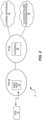
- Each subcarrier taken at each transmission time may be regarded as Resource Element, or RE, and Figure 1 can be understood as depicting some portion of an OFDM time-frequency grid, with CRS and DMRS being transmitted on specific subcarriers at specific times. More particularly, one sees regular transmissions of CRS across the system bandwidth, along with the transmission of DMRS in conjunction with data transmission on scheduled resources.
- the DRMS sequence element transmitted on a given subcarrier depends on the position of the subcarrier within the overall plurality of subcarriers constituting the overall system bandwidth. For example, with the subcarriers are numbered from 0 to N, the sequence element associated with the m -th subcarrier depends on the value of m.
- This approach can be understood as a "global" numbering scheme that applies to the system bandwidth and, importantly, LTE UEs support the full system bandwidth.
- the pseudo-random sequence c ( i ) is defined by a length-31 Gold sequence.
- NR denotes the New Radio standard at issue in the ongoing development of next-generation communication networks, which are also referred to as 5G networks.
- NR contemplates wide system bandwidths-e.g., bandwidths of 1 GHz or more-and not every terminal operating in an NR system will have the capability to operate over the complete system bandwidth
- the NR will, therefore, provide support for terminals capable of supporting only a fraction of the system bandwidth.
- the network configures a portion of the system bandwidth for use by the terminal, referred to as terminal's configured bandwidth, and then uses bandwidth within the configured bandwidth for scheduling the terminal, referred to as the terminal's scheduled bandwidth.
- a terminal may perform access to an NR carrier by detecting a synchronization signal and broadcast channel and performing a subsequent random access. After random access, the network could configure the terminal to a new frequency relative to the frequency used for initial access. This approach does not require the terminal to know the system bandwidth or know where its configured bandwidth lies within the system bandwidth.
- Methods and apparatuses disclosed herein enable the use of Demodulation Reference Signal, DMRS, sequences that are numbered relative to an overall system bandwidth, while simultaneously enabling wireless communication devices to determine the DRMS sequence elements mapped to their scheduled bandwidths within the system bandwidth.
- the wireless communication devices need not know the system bandwidth or even be aware of where their scheduled bandwidths reside within the system bandwidth.
- An example method of operation at a wireless communication device includes determining, based on information received from a wireless communication network, a sequence offset for a reference signal sequence, e.g., a DMRS sequence. The method further includes determining, based on the sequence offset, which portion of the reference signal sequence overlays a scheduled bandwidth of the wireless communication device, referred to as an overlaying portion 44 of the reference signal sequence.
- the scheduled bandwidth is a portion of a larger, system bandwidth associated with the network, and the reference signal sequence overlays the system bandwidth according to a defined mapping between respective sequence elements constituting the reference signal sequence and respective subcarriers constituting the system bandwidth.
- a wireless communication device is configured for operation in a wireless communication network and comprises communication circuitry configured for wirelessly communicating with one or more nodes in the network, and processing circuitry that is operatively associated with the communication circuitry.
- the processing circuitry is configured to determine, based on information received from the network, a sequence offset for a reference signal sequence, and determine, based on the sequence offset, which portion of the reference signal sequence overlays a scheduled bandwidth of the wireless communication device. Such portion is referred to as an overlaying portion of the reference signal sequence.
- the scheduled bandwidth is a portion of a larger, system bandwidth associated with the network, and the reference signal sequence overlays the system bandwidth according to a defined mapping between respective sequence elements constituting the reference signal sequence and respective subcarriers constituting the system bandwidth.
- a method of operation at a network node configured for operation in a wireless communication network includes determining a value from which a wireless communication device can determine which portion of a reference signal sequence overlays a scheduled bandwidth of the wireless communication device.
- the scheduled bandwidth is within a configured bandwidth that is configured for the wireless communication device and within a larger system bandwidth, and the reference signal sequence overlays the system bandwidth according to a defined mapping between respective sequence elements comprising the reference signal sequence and respective subcarriers comprising the system bandwidth.
- the method further includes the network node signaling the value to the wireless communication device, thereby enabling the wireless communication device to determine the overlaying portion of the reference signal sequence and correspondingly identify which sequence elements of the reference signal sequence are associated with the subcarriers in the scheduled bandwidth.
- a network node comprises communication circuitry configured to communicate directly or indirectly with a wireless communication device operating in the network.
- the network node further includes processing circuitry that is operatively associated with the communication circuitry and configured to determine a value from which a wireless communication device can determine which portion of a reference signal sequence overlays a scheduled bandwidth of the wireless communication device. That portion of the sequence is referred to as an overlying portion, and the scheduled bandwidth is within a configured bandwidth that is configured for the wireless communication device.
- the configured bandwidth is within a larger system bandwidth
- the reference signal sequence overlays the system bandwidth according to a defined mapping between respective sequence elements constituting the reference signal sequence and respective subcarriers constituting the system bandwidth.
- the processing circuitry is further configured to signal the value to the wireless communication device. Such signaling enables the wireless communication device to determine the overlaying portion of the reference signal sequence and correspondingly identify which sequence elements of the reference signal sequence are associated with the subcarriers in the configured bandwidth.
- FIG. 2 illustrates one embodiment of a wireless communication network 16, "network 16".
- the network 16 provides one or more communication services to a wireless communication device 12, "device 12", such as by communicatively coupling the device 12 to one or more external networks 14 such as the Internet or other Packet Data Networks, PDNs.
- the network 16 includes a Radio Access Network, RAN, 18.
- the RAN 18 includes one or more radio network nodes 20, which may be referred to as base stations, access points, transmission points, etc.
- a Core Network, CN, 22 provides, e.g., mobility management and packet routing for the device 12, and includes one or more CN nodes 24, such as packet gateways, mobility management entities, authentication servers, etc.
- the network 16 may further include or be associated with one or more cloud-based or centralized processing nodes that provide processing services for various functions within the network 16.
- the network 16 may include multiple other nodes of the same or different types, and may include multiple radio network nodes 20 and may include more than one RAN and may operate with more than one Radio Access Technology, RAT.
- different types of radio network nodes 20 provide a heterogeneous radio access network, which may involve more than one RAT.
- the network 16 may use beamforming, e.g., wherein allocated beams within a potentially large plurality of beams from one or more radio network nodes 20 are used to provide coverage to the device 12.
- the device 12 comprises essentially any apparatus configured for wirelessly connecting to the network 16 via any one or more of the Radio Access Technologies, RATs, used by the network 16.
- the device 12 may be mobile, although fixed devices are also contemplated, and non-limiting examples include cellular radiotelephones, which may be smartphones or feature phones, laptops, tablets, wireless modems or adapters, Machine-to-Machine, M2M, or Machine-Type-Communication, MTC, devices, Internet-of-Things, IoT, devices, etc.
- Figure 3 depicts an example embodiment contemplated in the context of the device 12 and the network 16, where a system bandwidth 30 is associated with the network 16.
- the system bandwidth represents the air-interface bandwidth supported by a radio network node 20 in the RAN 18, operating as an NR transmission point or transceiver.
- the device 12 supports a fraction of the system bandwidth 30, which constitutes a plurality of frequency subcarriers 32.
- the subcarriers 32 may be numbered from low to high frequency, high to low frequency, or according to some other ordered scheme.
- Figure 3 may be regarded as depicting a scenario where the operation bandwidth capabilities of the radio network node 20 differ from the operation bandwidth capabilities of the device 12.
- the device 12 is associated with a configured bandwidth 34, as configured by the network 16, which is contained with the system bandwidth 30 but comports with the bandwidth limitations of the device 12.
- the network 16 schedules the device 12, for data transmissions or receptions, using a scheduled bandwidth 36, which is contained with the configured bandwidth 34.
- a given node 20 in the RAN 18 may support many devices 12 within its system bandwidth 30 and may locate the corresponding configured bandwidths 34 at various positions within the overall system bandwidth 30.
- the collection of subcarriers 32 shown as constituting the system bandwidth 30-seen on the left side of the page- may be numbered according to some global scheme.
- a reference signal sequence 40-seen on the right side of the page- maps to or aligns with the system bandwidth 30.
- the correspondence between respective sequence elements 42 in the reference signal sequence 40 and respective subcarriers 32 in the system bandwidth 30 is suggested by the horizontal alignment shown between them in the diagram.
- the depicted mapping is shown by way of example and not limitation, and it will be appreciated that the general idea here is that there is a defined association between subcarriers 32 in the system bandwidth 30 and sequence elements 42 in the reference signal sequence 40.
- the reference signal sequence 40 comprises a DMRS sequence generated such that each sequence element 42 depends on the number of its corresponding subcarrier 32, which subcarriers 32 are numbered within the "global" system bandwidth 30. See, for example, the DMRS sequence generation scheme explained in the Background of this disclosure for LTE.
- the sequence elements 42 that correspond to the subcarriers 32 included within the scheduled bandwidth 36 of a given device 12 depend on where the scheduled bandwidth 36 is positioned within the system bandwidth 30.
- the configured bandwidth 34 of the device 12 is positioned at a frequency offset relative to a starting point of the system bandwidth 30, and the scheduled bandwidth 36 is positioned at a further offset relative to the start of the configured bandwidth 34.
- the scheduled bandwidth 36 size and position may vary within configured bandwidth 34, as part of ongoing scheduling operations. Referencing the global numbering of the system bandwidth 30, the configured bandwidth 34 starts at point A in the system bandwidth 30 and goes to point C in the system bandwidth 30, while the scheduled bandwidth 36 goes from points B to C.
- the reference signal sequence 40 maps to, corresponds to, aligns with, or "overlays" the system bandwidth 30, according to a defined mapping, a particular portion 44 of the reference signal sequence 40 overlays the scheduled bandwidth 36 of the device 12.
- the sequence elements 42 going from point E to point F in the reference signal sequence 40 overlay-map to-the subcarriers 32 going from point B to C in the system bandwidth 30. More generally, the sequence segment from point D to F overlays the bandwidth segment from point A to C.
- Figure 4 illustrates another view of the system bandwidth 30, this time shown in the context of a time-frequency grid, where the intersection between transmission times and subcarriers 32 represents "resource elements" or REs 38. It will be understood that the transmission or reception of a sequence element 42 on its corresponding subcarrier 32 means the transmission or reception on a resource element 38 defined on that subcarrier 32.
- methods and apparatuses disclosed herein enable the device 12 to determine the overlaying portion 44 of the reference signal sequence 40, without having to know the system bandwidth 30.
- the device 12 determines the overlaying portion 44 of the reference signal sequence 40 without an explicit knowledge of where its scheduled bandwidth 36 is positioned within the system bandwidth 30.
- Figure 5 depicts example embodiments of a device 12 and a network node 50, which are configured to carry out the respective device-side and network-side operations disclosed herein.
- the node 50 may be implemented in various network locations, such as in the RAN 18, in the CN 22, or as a cloud-based node 26. Further, the node 50 may comprise two or more nodes- i.e., its functionality may be distributed. In at least one embodiment, the node 50 is co-located with or implemented in the radio network node 20 seen in Figure 2 , and it will be understood that there may be multiple such nodes 20 in the network 16.
- the node 50 includes communication circuitry 52 that is configured for communicating directly or indirectly with the device 12.
- the communication circuitry 52 includes radio frequency, RF, transceiver circuitry, i.e., transmit and receive circuits, configured for transmitting signals on the downlink to one or more devices 12 and for receiving signals on the uplink from such devices 12.
- the communication circuitry 52 includes one or more network or computer data interfaces, for communicating with one or more other nodes in the network 16.
- the node 50 communicates indirectly with the device 12 by sending signaling towards another node that provides the air interface for wirelessly coupling to the device 12.
- the node 50 further includes processing circuitry 54 that is operatively associated with the communication circuitry 52 and includes or is associated with storage 56.
- the processing circuitry 54 comprises fixed circuitry, or programmed circuitry, or a mix of fixed and programmed circuitry.
- the processing circuitry 54 comprises one or more microprocessors, Digital Signal Processors, DSPs, Field Programmable Gate Arrays, FPGAs, Application Specific Integrated Circuits, ASICS, or other digital processing circuitry.
- the processing circuitry 54 is configured according to the teachings herein based on its execution of computer program instructions stored in one or more computer programs 58 held in the storage 56.
- the storage 56 may further hold one or more items of configuration data 60 that are pre-provisioned and/or dynamically acquired by the processing circuitry 54.
- the storage 56 comprises one or more types of computer-readable media, such as a mix of nonvolatile memory circuits or disk storage, along with volatile, working memory.
- Non-limiting examples of non-volatile storage include Solid State Disk, SSD, storage, FLASH, and EEPROM, while non-limiting examples of volatile, working memory include DRAM or SRAM circuitry.
- the communication circuitry 52 is configured to communicate directly or indirectly with a device 12 operating in the network 16, and the processing circuitry 54 is operatively associated with the communication circuitry 52 and configured to perform several functions or operations.
- the processing circuitry 54 is configured to determine a value from which the device 12 can determine which portion of a reference signal sequence 40 overlays a scheduled bandwidth 36 of the device 12.
- the scheduled bandwidth 36 is in a configured bandwidth 34 that is configured for the device 12.
- the configured bandwidth 34 lies within the system bandwidth 30.
- a defined mapping determines the correspondence between sequence 40 and the system bandwidth 30, i.e., defines a mapping between respective sequence elements 42 constituting the reference signal sequence 40 and respective subcarriers 32 constituting the system bandwidth 30.
- the configured bandwidth 34 for the wireless communication device 12 may be configured by the processing circuitry 54.
- the scheduled bandwidth 36 may be dynamically selected by the processing circuitry 54, as part of a scheduling function implemented therein.
- the processing circuitry 54 is further configured to signal the value to the device 12, thereby enabling the device 12 to determine the overlaying portion 44 of the reference signal sequence 40 and correspondingly identify which sequence elements 42 of the reference signal sequence 40 are associated with the subcarriers 32 in the scheduled bandwidth 36.
- the value may be signaled to the device 12 in conjunction with configuring the configured bandwidth 34.
- the processing circuitry 54 determines the value as a seed value for seeding a sequence element generation function at the wireless communication device. Because the seed value controls where in the reference signal sequence 40 the generator "begins", the processing circuitry 54 can provide the device 12 with the applicable sequence offset on an implicit basis. That is, the processing circuitry 54 can provide the device 12 with the seed value corresponding to the start of its configured bandwidth 34, such that sequence element generation at the device 12 begins with the first sequence element 42 in the configured bandwidth 34.
- the device 12 knows the position of its scheduled bandwidth 36 within the configured bandwidth 34, knowing the starting sequence element 42 means that it knows the sequence elements 42 that correspond to the subcarriers 32 in its scheduled bandwidth 36-i.e., it knows the overlaying portion 44 of the reference signal sequence 40.
- the approach works without the device 12 having to know the system bandwidth 30 and without the device having to know the position of its configured bandwidth 34 within the system bandwidth 30.
- Significant reductions in signaling overhead and bandwidth management complexity attend the approach.
- the processing circuitry 54 is configured to determine the value it signals to the device 12 as an offset value that identifies a sequence offset corresponding to the overlaying portion 44 of the reference signal sequence 40, or that identifies a position offset of the configured bandwidth 34 within the system bandwidth 30. In this latter case, the sequence offset is derivable at the wireless communication device 12.
- the processing circuitry 54 is configured to determine the value as an offset value that relates the configured bandwidth 34 to a reference position within the system bandwidth 30.
- the processing circuitry 54 is configured to determine which sequence elements from an uplink reference signal sequence are included in, or interfere with, the uplink transmission. The determination is based on a position of the scheduled bandwidth 36 within the system bandwidth 30 and the defined mapping.
- the device 12 may be less complex than the node 50, it may similarly comprise digital processing circuitry and associated communication circuitry.
- the device 12 includes communication circuitry 72 that is configured for receiving downlink signals from the network 16 and transmitting uplink signals to the network 16.
- the communication circuitry 72 includes radio frequency, RF, transceiver circuitry configured for transmitting on the uplink to one or more radio network nodes 20 and for receiving on the downlink from one or more radio network nodes 20.
- the communication circuitry 72 may also support Device-to-Device, D2D, communications directly with other devices 12 and may include WLAN communications, Bluetooth communications, Near-Field Communication, NFC, etc.
- the device 12 further includes processing circuitry 74 that is operatively associated with the communication circuitry 72 and includes or is associated with storage 76.
- the processing circuitry 74 comprises fixed circuitry, or programmed circuitry, or a mix of fixed and programmed circuitry.
- the processing circuitry 74 comprises one or more microprocessors, DSPs, FPGAs, ASICS, or other digital processing circuitry.
- the processing circuitry 74 is configured according to the teachings herein based on the execution of computer program instructions stored in one or more computer programs 78 held in storage 76.
- the storage 76 may further hold one or more items of configuration data 80 that are pre-provisioned and/or dynamically acquired by the processing circuitry 74.
- the configuration data 80 includes, for example, the value signaled to the device 12 by the network 16, for determining the overlaying portion 44 of the reference signal sequence 40.
- the storage 76 comprises one or more types of computer-readable media, such as a mix of nonvolatile memory circuits or disk storage and volatile, working memory.
- Non-limiting examples of non-volatile storage include SSD storage, FLASH, and EEPROM, while non-limiting examples of the volatile, working memory include DRAM or SRAM circuitry.
- the communication circuitry 72 is configured for wirelessly communicating with one or more nodes in the network 16, e.g., with one or more radio network nodes 20.
- the processing circuitry 74 is operatively associated with the communication circuitry 72, e.g., it obtains data or control information via received signals incoming to the communication circuitry 72, and it sends data or control information via signals transmitted from communication circuitry 72. Further, the processing circuitry 74 is configured to determine, based on information received from the network 16, a sequence offset for a reference signal sequence 40 and determine, based on the sequence offset, which portion of the reference signal sequence 40 overlays a scheduled bandwidth 36 of the device 12.
- the overlaying portion referred to as an overlaying portion 44 of the reference signal sequence 40 and, as noted before, the scheduled bandwidth 36 is a portion of a larger, system bandwidth 30 associated with the network 16.
- the reference signal sequence 40 overlays the system bandwidth 30 according to a defined mapping between respective sequence elements 42 constituting the reference signal sequence 40 and respective subcarriers 32 constituting the system bandwidth 30.
- the processing circuitry 74 is configured to perform at least one of: transmit one or more of the sequence elements 42 contained in the overlaying portion 44 of the reference signal sequence 40; decode based on one or more of the sequence elements 42 contained in the overlaying portion 44 of the reference signal sequence 40; cancel interference based on one or more of the sequence elements 42 contained in the overlaying portion 44 of the reference signal sequence 40; and estimate a channel based on one or more of the sequence elements 42 contained in the overlaying portion 44 of the reference signal sequence 40.
- the information received from the network 16 directly or indirectly indicates a position of a configured bandwidth 34 within the system bandwidth 30.
- the processing circuitry 74 is configured to determine the sequence offset based on the position of the configured bandwidth 34 and a position of the scheduled bandwidth 36 within the configured bandwidth 34. That is, the position of the configured bandwidth 34 within the system bandwidth 30 defines a first offset into the reference signal sequence 40, and the position of the scheduled bandwidth 36 within the configured bandwidth 34 defines a further offset into the reference signal sequence 40.
- a seed value also may be provided by the network 16 as the information used by the processing circuitry 74 to determine the sequence offset.
- the processing circuitry 74 is configured to determine the sequence offset implicitly, by using the seed value to seed a sequence element generation function, wherein the seed value is a function of the sequence offset.
- the sequence element generation function as seeded by the seed value, generates sequence elements 42 corresponding to the configured bandwidth 34 of the device 12.
- the scheduled bandwidth 36 lies within the configured bandwidth 34 and the processing circuitry 74 is configured to determine the overlaying portion 44 of the reference signal sequence 40, based on a position of the scheduled bandwidth 36 within the configured bandwidth 34.
- the information received from the network 16 indicates an offset relating a position of a configured bandwidth 34 of the device 12 to a reference position within the system bandwidth 30, e.g., a reference subcarrier.
- the processing circuitry 74 is configured to determine the sequence offset based on the position of the configured bandwidth 34 in relation to the reference position, and further based on a position of the scheduled bandwidth 36 within the configured bandwidth 34.
- Knowing which sequence elements 42 correspond to the subcarriers 32 in its scheduled bandwidth 36 enables the device 12 to perform one or more receive and/or transmit operations. For example, knowing which sequence element 42 maps to a given subcarrier 32 within its scheduled bandwidth 36 allows the processing circuitry 74 to estimate the interference arising at the device 16 from the reception of that sequence element 42 from another node or device in the network 16.
- sequence element 40 there may be more than one sequence element 40 defined within the network 16, e.g., a base sequence and one or more cyclically-shifted versions of the base sequence. If all such sequences 40 have the same element-to-subcarrier mapping defined relative to the system bandwidth 30, the device 16 may not know precisely which sequence element 42 it receives as interference, but it will know the set of possible sequence elements 42, which greatly limits the number of interference hypotheses it must consider.
- the processing circuitry 74 is configured to estimate interference at the device 12, as arising from a reference signal transmission by another device or node, as a function of one or more of the sequence elements 42 contained in the overlaying portion 44 of a reference signal sequence 40.
- the sequence elements 42 contained in the overlaying portion 44 of the reference signal sequence 40 depend on a cyclic shift used by the interfering node or device, and the processing circuitry 74 is configured to estimate the interference by hypothesizing the cyclic shift according to a known set of possible cyclic shifts.
- Figures 6 and 7 depict example embodiments of processing at a device 12 and a network node 50, respectively.
- the method 600 as performed by a device 12, includes determining (Block 602), based on information received from the network 16, a sequence offset for a reference signal sequence 40, and determining (Block 604), based on the sequence offset, which portion of the reference signal sequence 40 overlays a scheduled bandwidth 36 of the device 12.
- the method 600 may further include an earlier step or operation of receiving the information in question, such as during a configuration operation in which the network 16 determines the configured bandwidth 34 of the device 16.
- the method 700 includes determining (Block 702) a value from which a device 12 can determine which portion of a reference signal sequence 40 overlays a scheduled bandwidth 36 of the device 12, and signaling (Block 704) the value to the device 12.
- the scheduled bandwidth 36 is contained within a configured bandwidth 34 of the device 12, and the method 700 may further include a step or operation of configuring the configured bandwidth 34 for the device 12 and signaling the value to the device 12 may occur in conjunction with the bandwidth configuration operations. Signaling such information to the device 12 enables it to determine the overlaying portion 44 of the reference signal sequence 40 and correspondingly identify which sequence elements 42 of the reference signal sequence 40 are associated with the subcarriers 32 in the scheduled bandwidth 36.
- an offset parameter which may also be referred to as a "value” or as "information" is signaled from the network 16 to the device 12, which enables the device 12 to determine the sequence elements 42 of a reference signal sequence 40 that overlap with its scheduled bandwidth 36 or its configured bandwidth 34.
- the reference signal sequence 40 is, for example, a DMRS sequence, and its sequence elements are numbered globally, e.g., relative to the system bandwidth 30. The device 12 may not know the system bandwidth 30.
- the signaled parameter enables the device 12 to determine the DMRS sequence element that is mapped to the lowest frequency of its configured bandwidth 34.
- the offset parameter indicates the start of the DMRS sequence, for example.
- the offset parameter could, of course, be configured to indicate the DMRS sequence element mapped to other positions, such as the highest frequency, the middle frequency, etc.
- Figure 8 depicts a corresponding example involving victim device 12 and two aggressor devices-e.g., the victim device 12 is a first UE and the two aggressor devices are other, nearby UEs.
- the device 12 can determine that DMRS sequence element 3 is the sequence element that maps to the first DMRS position within its configured bandwidth 34. So, in the simplest case, the parameter signaled to the device 12 by the network 16 could indicate "3".
- the actual values of the DMRS sequence elements that map to its scheduled bandwidth 36 can be derived from device 12 specific parameters and/or cell-wide parameters such as virtual cell ID.
- the signaled parameter directly indicates the first or a specified DMRS sequence element of the scheduled bandwidth 36 instead of the configured bandwidth 34.
- the parameter would need to be signaled only with changes in the configured bandwidth 34.
- the device 12 is configured with a bandwidth after the device 12 makes an initial access.
- the parameter required to determine the DMRS sequence alignment with the device's scheduled bandwidth 36 is derivable at the device 12 from the configuration and explicit signaling is not needed.
- a reference subcarrier in the system bandwidth 30 is defined.
- the primary synchronization signal, PSS is transmitted by the network 16 and received and detected by the device 12.
- the center position of the detected PSS can be identified as the reference subcarrier, or, more generally, any subcarrier 32 in the system bandwidth 30 can be defined as a reference subcarrier.
- the operating bandwidth that is configured to the device 12 is signaled, by indicating a frequency distance relative to the reference subcarrier 32. The distance may be indicated in terms of subcarriers 32, or corresponding Resource Blocks, etc.
- the DMRS sequence r ( m ) is generated per subcarrier m relative to the reference subcarrier, where m may be both positive and negative, as to create a global numbering scheme. Knowing the frequency distance from the reference subcarrier, although it is outside the operating bandwidth for the device 12, enables the device 12 to determine the DMRS sequence for its scheduled resource blocks.
- Each aggressor device has a scheduled bandwidth that at least partially overlaps the scheduled bandwidth 36 of the device 12.
- any frequency position that is common between the scheduled bandwidth 36 of the device 12 and the aggressor devices 1 and 2 will map to the same DMRS sequence position.
- the device 12 knows which DMRS sequences could be in use at the aggressor devices, it knows precisely which DMRS sequence elements could be received at the device 12 from the aggressor devices, on the subcarriers 32 included in its scheduled bandwidth 36.
- DMRS sequences there may be a limited number of DMRS sequences defined, e.g., by using a base DMRS sequence and a defined set of cyclic shifts. Each cyclic shift can be thought of as producing a different DMRS sequence.
- the sequence elements in each such DMRS sequence all observe the global mapping, i.e., the sequence positions in each DMRS sequence map to the frequency positions of the system bandwidth 30 per the same global numbering and mapping.
- the actual value of the sequence element in sequence position "x" in a first DMRS sequence will differ from the value of sequence element in sequence position "x" in a second DMRS sequence.
- sequence position "x" from both sequences maps to the same frequency position in the global system bandwidth.
- the device 12 knows the DMRS sequences that are possible for use at the aggressor devices-e.g., knows the possible cyclic shifts-it knows the universe of values possible for the DRMS sequence element(s) it receives on the subcarrier 32 corresponding to the involved sequence position.
- the interfering DMRS sequence elements from the aggressor devices 1 and 2 overlapping the scheduled bandwidth 36 of the device 12 are also elements 4 to 6.
- the device 12 needs only to test one or a few sequence candidates, but not different sequence positions.
- the device 12 could, for example, know the cell ID from neighboring transmission points-e.g., radio network nodes 20-and derive the one or few DM-RS sequences connected to the transmission point from the virtual cell ID of that transmission point.
- the network 16 Another possibility for the network 16 to provide the information needed by the device 12 to determine the DMRS sequence positions that correspond to the frequency positions of its scheduled bandwidth 36 is to signal a seed value.
- the sequence used for DMRS is a pseudo-random sequence generated by a pseudo random sequence generator that is initialized with a specified seed value, e.g., c_init.
- the pseudo random sequence generator could be initialized with a seed value and generates a sequence which is then mapped to the global DMRS sequence starting with sequence element 0, which is mapped to the lowest DM-RS element within the system bandwidth 36.
- the 4th sequence element is the first DM-RS element within the configured bandwidth 34 of the device 12.
- the pseudo random sequence generator in the device 12 could be configured with the seed value that produces the same pseudo random sequence but starting with sequence element 4, labeled as DMRS3 in the diagram.
- c_init there is a set of possible seed values c_init, corresponding to a set of reference subcarriers within the system bandwidth.
- the device 12 is signaled the offset to the nearest reference subcarrier and the identity of the reference subcarrier.
- the shift register values need to be stored. For example, if m -sequences are used as in LTE, x_1(n), x_2(n) needs to be stored for a range of n.
- a device 12 can store the shift register memory values corresponding to the sequence elements mapped to a set of reference subcarriers, e.g., with 100 MHz spacing.
- the benefit of this is that the forward generation of a sequence would be limited to at most 100 MHz, which is the longest distance from the device's configured bandwidth 34 to a reference subcarrier. Otherwise, for very large system bandwidths, e.g., 1 GHz, the forward generation of the sequence r ( m ) to the configured bandwidth 34 would be demanding.
- the network 16 in one or more embodiments is configured to signal a parameter to a device 12 that the device 12 uses to determine its reference signal, i.e., to determine which portion of a reference signal sequence corresponds to its scheduled bandwidth 36.
- This arrangement enables the device 12 to determine which DMRS sequence elements apply to the scheduled bandwidth 36, without the device 12 having to know the system bandwidth 30 or the position of its scheduled bandwidth 36 within the system bandwidth 30.
- Such an approach allows the network 16 to relate or map DMRS sequence positions to frequency positions in the system bandwidth 30 using a global numbering scheme.
- the parameter signaled by the network 16 to a device 12 could be an offset parameter that informs the device 12 which part to "cut out" of a global DMRS sequence, e.g., it could be the reference signal sequence element number that maps to the beginning of the configured bandwidth 34 of the device 12. This parameter, together with the device's knowledge of where its scheduled bandwidth 36 is within its configured bandwidth 34, would enable the device 12 to determine the reference signal sequence elements mapped to its scheduled bandwidth 36.
- the signaled parameter could also be a seed parameter that informs the device 12 how to initialize its pseudo random sequence generator, assuming a pseudo random sequence is used for DM-RS. The first generated sequence element would again correspond to the reference signal sequence element mapped to the beginning of the device's configured bandwidth 34.
- Such operations enable a global numbering of DMRS sequences relative to system bandwidth, even if the device 12 is not aware of the system bandwidth 30 or its bandwidth position relative to the system bandwidth 30.
- a victim device 12 Independent of victim and aggressor frequency position, a victim device 12 knows which sequence element numbers of the aggressor DM-RS sequence overlap its scheduled bandwidth 36 and by that can easily cancel the interfering DMRS.
- the DMRS only depend on the cell ID or a similar parameter such as virtual cell ID; if the victim device 12 knows the cell ID of the interfering node it also knows the interfering sequence elements.
- a given transmission point may be associated with one cell ID but may create pseudo orthogonal reference signals. Even in this case, if the victim device 12 knows the cell ID it only has to test a few candidate sequences to cancel interference arising at the device 12 from transmission of the reference signal(s) by the transmission point.
- Figure 9 emphasizes this scenario by showing the global alignment between reference signal sequence positions for a victim device 12 and two aggressor devices 1 and 2. Particularly, one sees that the same sequence position numbering-which generally relates to the frequency position numbering of the system bandwidth 30-applies to the victim device 12 and to the aggressor devices 1 and 2. That is, the portion 44-1 of a reference signal sequence that overlays the scheduled bandwidth of the victim device 12 uses the same sequence position numbering/mapping as is used for the portions 44-2 and 44-3 that overlay the scheduled bandwidths of the aggressor devices 1 and 2. Note that actual reference signal sequences are not necessarily the same for the three devices. That is, the sequence element associated sequence position 4 in each of the overlaying portions 44-1, 44-2, and 44-3, may have a different value, but the alignment or mapping of that sequence position is the same for all three devices.
- each such reference signal sequence 40 comprises a series or set of sequence elements 42, with each sequence element occupying a corresponding position in the reference signal sequence 40.
- the network 16 e.g., a given radio network node 20, uses a global numbering scheme for its system bandwidth 30, e.g., a global numbering scheme for the frequency subcarriers 32 constituting its system bandwidth 30.
- Each subcarrier 32 may be regarded as occupying a frequency position, and the network 16 uses a defined mapping that relates reference signal positions to frequency positions.
- a device 12 is configured with a configured bandwidth 34, where the configured bandwidth 34 is positioned somewhere within the system bandwidth 30.
- the device 12 uses a scheduled bandwidth 36 that occupies all or a portion of the configured bandwidth 34. Because of the defined mapping or alignment between reference signal sequence positions and frequency positions, the sequence positions that correspond with the frequency positions associated with the device's scheduled bandwidth 36 are dictated by where the scheduled bandwidth 36 is positioned within the system bandwidth 30. However, according to the teachings herein, the device 12 does not need to know the system bandwidth 30, or even know the position of its configured/scheduled bandwidth 34/36, to know which reference signal sequence positions correspond to its scheduled bandwidth 36. Those needs are obviated by the network 16 signaling information to the device 12 from which the device 12 can implicitly or explicitly determine the sequence offset corresponding to its system bandwidth 36.
Abstract
Description
- The present invention relates to communication networks and particularly relates to determining reference signal offsets in a communication network.
- Networks based on the Long Term Evolution, LTE, specifications, as promulgated by the Third Generation Partnership Project, 3GPP, use two kinds of reference signals: Cell-specific Reference Signals or CRS, and Demodulation Reference Signals or DMRS, which are also denoted as DM-RS. CRS span the complete "system" bandwidth involved and they are "always on." In contrast, DMRS span only the scheduled bandwidth to which they pertain and they are only transmitted when transmitting data.
- The advantage of reference signals that are always transmitted is that a wireless communication device, referred to as a UE or User Equipment in 3GPP parlance, can rely on their presence. Drawbacks associated with CRS include a high network energy consumption because CRS are even transmitted if no data are transmitted. CRS also create unnecessary interference because they are transmitted even if not needed.
- See
Figure 1 , which illustrates an example system bandwidth and the transmission of CRS and DMRS within the system bandwidth. In an Orthogonal Frequency Division Multiplex, OFDM, example applicable to the LTE context, the system bandwidth comprises a plurality of spaced-apart, narrow-band subcarriers that, in the aggregate, span the system bandwidth. Each subcarrier taken at each transmission time may be regarded as Resource Element, or RE, andFigure 1 can be understood as depicting some portion of an OFDM time-frequency grid, with CRS and DMRS being transmitted on specific subcarriers at specific times. More particularly, one sees regular transmissions of CRS across the system bandwidth, along with the transmission of DMRS in conjunction with data transmission on scheduled resources. - In LTE, the DRMS sequence element transmitted on a given subcarrier depends on the position of the subcarrier within the overall plurality of subcarriers constituting the overall system bandwidth. For example, with the subcarriers are numbered from 0 to N, the sequence element associated with the m-th subcarrier depends on the value of m. This approach can be understood as a "global" numbering scheme that applies to the system bandwidth and, importantly, LTE UEs support the full system bandwidth.
- In more detail, in LTE, for any of the antenna ports p ∈ {7,8,...,υ + 6}, the reference-signal sequence r(m) used for DMRS on subcarrier m within the downlink, DL, system bandwidth


- The pseudo-random sequence c(i) is defined by a length-31 Gold sequence.
- The output sequence c(n) of length M PN, where n = 0,1,...,M PN -1, is defined by


- x 1(0) = 1,x 1(n) = 0,n = 1,2,...,30. The initialization of the second m-sequence is denoted by

- The pseudo-random sequence generator shall for DMRS in LTE be initialized with

- The quantities

-


-

- It is recognized herein that certain complications arise concerning the generation and use of DRMS signals in the context of NR, where "NR" denotes the New Radio standard at issue in the ongoing development of next-generation communication networks, which are also referred to as 5G networks. NR contemplates wide system bandwidths-e.g., bandwidths of 1 GHz or more-and not every terminal operating in an NR system will have the capability to operate over the complete system bandwidth
- NR will, therefore, provide support for terminals capable of supporting only a fraction of the system bandwidth. For example, the network configures a portion of the system bandwidth for use by the terminal, referred to as terminal's configured bandwidth, and then uses bandwidth within the configured bandwidth for scheduling the terminal, referred to as the terminal's scheduled bandwidth.
- A terminal may perform access to an NR carrier by detecting a synchronization signal and broadcast channel and performing a subsequent random access. After random access, the network could configure the terminal to a new frequency relative to the frequency used for initial access. This approach does not require the terminal to know the system bandwidth or know where its configured bandwidth lies within the system bandwidth.
- Methods and apparatuses disclosed herein enable the use of Demodulation Reference Signal, DMRS, sequences that are numbered relative to an overall system bandwidth, while simultaneously enabling wireless communication devices to determine the DRMS sequence elements mapped to their scheduled bandwidths within the system bandwidth. Advantageously, the wireless communication devices need not know the system bandwidth or even be aware of where their scheduled bandwidths reside within the system bandwidth.
- An example method of operation at a wireless communication device includes determining, based on information received from a wireless communication network, a sequence offset for a reference signal sequence, e.g., a DMRS sequence. The method further includes determining, based on the sequence offset, which portion of the reference signal sequence overlays a scheduled bandwidth of the wireless communication device, referred to as an
overlaying portion 44 of the reference signal sequence. Here, the scheduled bandwidth is a portion of a larger, system bandwidth associated with the network, and the reference signal sequence overlays the system bandwidth according to a defined mapping between respective sequence elements constituting the reference signal sequence and respective subcarriers constituting the system bandwidth. - In a corresponding example, a wireless communication device is configured for operation in a wireless communication network and comprises communication circuitry configured for wirelessly communicating with one or more nodes in the network, and processing circuitry that is operatively associated with the communication circuitry. The processing circuitry is configured to determine, based on information received from the network, a sequence offset for a reference signal sequence, and determine, based on the sequence offset, which portion of the reference signal sequence overlays a scheduled bandwidth of the wireless communication device. Such portion is referred to as an overlaying portion of the reference signal sequence. As before, the scheduled bandwidth is a portion of a larger, system bandwidth associated with the network, and the reference signal sequence overlays the system bandwidth according to a defined mapping between respective sequence elements constituting the reference signal sequence and respective subcarriers constituting the system bandwidth.
- In another example embodiment, a method of operation at a network node configured for operation in a wireless communication network includes determining a value from which a wireless communication device can determine which portion of a reference signal sequence overlays a scheduled bandwidth of the wireless communication device. The scheduled bandwidth is within a configured bandwidth that is configured for the wireless communication device and within a larger system bandwidth, and the reference signal sequence overlays the system bandwidth according to a defined mapping between respective sequence elements comprising the reference signal sequence and respective subcarriers comprising the system bandwidth. The method further includes the network node signaling the value to the wireless communication device, thereby enabling the wireless communication device to determine the overlaying portion of the reference signal sequence and correspondingly identify which sequence elements of the reference signal sequence are associated with the subcarriers in the scheduled bandwidth.
- In a corresponding example, a network node comprises communication circuitry configured to communicate directly or indirectly with a wireless communication device operating in the network. The network node further includes processing circuitry that is operatively associated with the communication circuitry and configured to determine a value from which a wireless communication device can determine which portion of a reference signal sequence overlays a scheduled bandwidth of the wireless communication device. That portion of the sequence is referred to as an overlying portion, and the scheduled bandwidth is within a configured bandwidth that is configured for the wireless communication device. In turn, the configured bandwidth is within a larger system bandwidth, and the reference signal sequence overlays the system bandwidth according to a defined mapping between respective sequence elements constituting the reference signal sequence and respective subcarriers constituting the system bandwidth.
- The processing circuitry is further configured to signal the value to the wireless communication device. Such signaling enables the wireless communication device to determine the overlaying portion of the reference signal sequence and correspondingly identify which sequence elements of the reference signal sequence are associated with the subcarriers in the configured bandwidth.
- Of course, the present invention is not limited to the above features and advantages. Those of ordinary skill in the art will recognize additional features and advantages upon reading the following detailed description, and upon viewing the accompanying drawings.
-
-
Figure 1 is a diagram of example CRS and DMRS transmission. -
Figure 2 is a block diagram of one embodiment of a wireless communication network. -
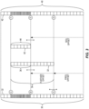
Figure 3 is a diagram of one embodiment of a defined mapping between a reference signal sequence and a system bandwidth. -
Figure 4 is a diagram illustrating resource elements corresponding to a time-frequency grid. -
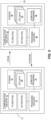
Figure 5 is a block diagram illustrating example embodiments of a wireless communication device and a network node. -
Figure 6 is a logic flow diagram illustrating one embodiment of a method of processing at a wireless communication device. -
Figure 7 is a logic flow diagram illustrating one embodiment of a method of processing at a network node. -
Figures 8 and9 are diagrams illustrating example cases of victim and aggressor devices having overlapping scheduled bandwidths. -
Figure 2 illustrates one embodiment of awireless communication network 16, "network 16". Thenetwork 16 provides one or more communication services to awireless communication device 12, "device 12", such as by communicatively coupling thedevice 12 to one or moreexternal networks 14 such as the Internet or other Packet Data Networks, PDNs. Thenetwork 16 includes a Radio Access Network, RAN, 18. TheRAN 18 includes one or moreradio network nodes 20, which may be referred to as base stations, access points, transmission points, etc. A Core Network, CN, 22 provides, e.g., mobility management and packet routing for thedevice 12, and includes one ormore CN nodes 24, such as packet gateways, mobility management entities, authentication servers, etc. Thenetwork 16 may further include or be associated with one or more cloud-based or centralized processing nodes that provide processing services for various functions within thenetwork 16. - The diagram shall be understood as being simplified, as the
network 16 may include multiple other nodes of the same or different types, and may include multipleradio network nodes 20 and may include more than one RAN and may operate with more than one Radio Access Technology, RAT. In one example, different types ofradio network nodes 20 provide a heterogeneous radio access network, which may involve more than one RAT. Further, in the context of New Radio, NR, 5G implementations, thenetwork 16 may use beamforming, e.g., wherein allocated beams within a potentially large plurality of beams from one or moreradio network nodes 20 are used to provide coverage to thedevice 12. - Still further, unless otherwise noted, the terms "device," "wireless communication device," "user equipment," and "UE" are used interchangeably herein. Unless otherwise specified, the
device 12 comprises essentially any apparatus configured for wirelessly connecting to thenetwork 16 via any one or more of the Radio Access Technologies, RATs, used by thenetwork 16. Thedevice 12 may be mobile, although fixed devices are also contemplated, and non-limiting examples include cellular radiotelephones, which may be smartphones or feature phones, laptops, tablets, wireless modems or adapters, Machine-to-Machine, M2M, or Machine-Type-Communication, MTC, devices, Internet-of-Things, IoT, devices, etc. -
Figure 3 depicts an example embodiment contemplated in the context of thedevice 12 and thenetwork 16, where asystem bandwidth 30 is associated with thenetwork 16. As a non-limiting example, the system bandwidth represents the air-interface bandwidth supported by aradio network node 20 in theRAN 18, operating as an NR transmission point or transceiver. Thedevice 12 supports a fraction of thesystem bandwidth 30, which constitutes a plurality offrequency subcarriers 32. Thesubcarriers 32 may be numbered from low to high frequency, high to low frequency, or according to some other ordered scheme. Thus,Figure 3 may be regarded as depicting a scenario where the operation bandwidth capabilities of theradio network node 20 differ from the operation bandwidth capabilities of thedevice 12. - The
device 12 is associated with a configuredbandwidth 34, as configured by thenetwork 16, which is contained with thesystem bandwidth 30 but comports with the bandwidth limitations of thedevice 12. Thenetwork 16 schedules thedevice 12, for data transmissions or receptions, using a scheduledbandwidth 36, which is contained with the configuredbandwidth 34. A givennode 20 in theRAN 18 may supportmany devices 12 within itssystem bandwidth 30 and may locate the corresponding configuredbandwidths 34 at various positions within theoverall system bandwidth 30. - As a non-limiting example, the collection of
subcarriers 32 shown as constituting the system bandwidth 30-seen on the left side of the page-may be numbered according to some global scheme. Correspondingly, a reference signal sequence 40-seen on the right side of the page- maps to or aligns with thesystem bandwidth 30. The correspondence betweenrespective sequence elements 42 in thereference signal sequence 40 andrespective subcarriers 32 in thesystem bandwidth 30 is suggested by the horizontal alignment shown between them in the diagram. - However, the depicted mapping is shown by way of example and not limitation, and it will be appreciated that the general idea here is that there is a defined association between
subcarriers 32 in thesystem bandwidth 30 andsequence elements 42 in thereference signal sequence 40. In an example, thereference signal sequence 40 comprises a DMRS sequence generated such that eachsequence element 42 depends on the number of its correspondingsubcarrier 32, which subcarriers 32 are numbered within the "global"system bandwidth 30. See, for example, the DMRS sequence generation scheme explained in the Background of this disclosure for LTE. - Within this framework, then, the
sequence elements 42 that correspond to thesubcarriers 32 included within the scheduledbandwidth 36 of a givendevice 12 depend on where the scheduledbandwidth 36 is positioned within thesystem bandwidth 30. In the diagramed example, the configuredbandwidth 34 of thedevice 12 is positioned at a frequency offset relative to a starting point of thesystem bandwidth 30, and the scheduledbandwidth 36 is positioned at a further offset relative to the start of the configuredbandwidth 34. Here, it may be noted that the scheduledbandwidth 36 size and position may vary within configuredbandwidth 34, as part of ongoing scheduling operations. Referencing the global numbering of thesystem bandwidth 30, the configuredbandwidth 34 starts at point A in thesystem bandwidth 30 and goes to point C in thesystem bandwidth 30, while the scheduledbandwidth 36 goes from points B to C. - Because the
reference signal sequence 40 maps to, corresponds to, aligns with, or "overlays" thesystem bandwidth 30, according to a defined mapping, aparticular portion 44 of thereference signal sequence 40 overlays the scheduledbandwidth 36 of thedevice 12. According to the labeling, thesequence elements 42 going from point E to point F in thereference signal sequence 40 overlay-map to-thesubcarriers 32 going from point B to C in thesystem bandwidth 30. More generally, the sequence segment from point D to F overlays the bandwidth segment from point A to C. -
Figure 4 illustrates another view of thesystem bandwidth 30, this time shown in the context of a time-frequency grid, where the intersection between transmission times andsubcarriers 32 represents "resource elements" or REs 38. It will be understood that the transmission or reception of asequence element 42 on its correspondingsubcarrier 32 means the transmission or reception on a resource element 38 defined on thatsubcarrier 32. - With the above framework in mind, methods and apparatuses disclosed herein enable the
device 12 to determine the overlayingportion 44 of thereference signal sequence 40, without having to know thesystem bandwidth 30. In at least some embodiments, thedevice 12 determines the overlayingportion 44 of thereference signal sequence 40 without an explicit knowledge of where its scheduledbandwidth 36 is positioned within thesystem bandwidth 30. -
Figure 5 depicts example embodiments of adevice 12 and anetwork node 50, which are configured to carry out the respective device-side and network-side operations disclosed herein. Thenode 50 may be implemented in various network locations, such as in theRAN 18, in theCN 22, or as a cloud-basednode 26. Further, thenode 50 may comprise two or more nodes- i.e., its functionality may be distributed. In at least one embodiment, thenode 50 is co-located with or implemented in theradio network node 20 seen inFigure 2 , and it will be understood that there may be multiplesuch nodes 20 in thenetwork 16. - Wherever implemented, in an example embodiment the
node 50 includes communication circuitry 52 that is configured for communicating directly or indirectly with thedevice 12. For example, the communication circuitry 52 includes radio frequency, RF, transceiver circuitry, i.e., transmit and receive circuits, configured for transmitting signals on the downlink to one ormore devices 12 and for receiving signals on the uplink fromsuch devices 12. Additionally, or alternatively, the communication circuitry 52 includes one or more network or computer data interfaces, for communicating with one or more other nodes in thenetwork 16. In at least one such example, thenode 50 communicates indirectly with thedevice 12 by sending signaling towards another node that provides the air interface for wirelessly coupling to thedevice 12. - The
node 50 further includesprocessing circuitry 54 that is operatively associated with the communication circuitry 52 and includes or is associated withstorage 56. Theprocessing circuitry 54 comprises fixed circuitry, or programmed circuitry, or a mix of fixed and programmed circuitry. In at least one embodiment, theprocessing circuitry 54 comprises one or more microprocessors, Digital Signal Processors, DSPs, Field Programmable Gate Arrays, FPGAs, Application Specific Integrated Circuits, ASICS, or other digital processing circuitry. In at least one such embodiment, theprocessing circuitry 54 is configured according to the teachings herein based on its execution of computer program instructions stored in one ormore computer programs 58 held in thestorage 56. Thestorage 56 may further hold one or more items ofconfiguration data 60 that are pre-provisioned and/or dynamically acquired by theprocessing circuitry 54. - In one or more embodiments, the
storage 56 comprises one or more types of computer-readable media, such as a mix of nonvolatile memory circuits or disk storage, along with volatile, working memory. Non-limiting examples of non-volatile storage include Solid State Disk, SSD, storage, FLASH, and EEPROM, while non-limiting examples of volatile, working memory include DRAM or SRAM circuitry. - In at least one embodiment, the communication circuitry 52 is configured to communicate directly or indirectly with a
device 12 operating in thenetwork 16, and theprocessing circuitry 54 is operatively associated with the communication circuitry 52 and configured to perform several functions or operations. Theprocessing circuitry 54 is configured to determine a value from which thedevice 12 can determine which portion of areference signal sequence 40 overlays a scheduledbandwidth 36 of thedevice 12. - As before, that portion of the
reference signal sequence 40 is referred to as an overlyingportion 44, and the scheduledbandwidth 36 is in a configuredbandwidth 34 that is configured for thedevice 12. In turn, the configuredbandwidth 34 lies within thesystem bandwidth 30. A defined mapping determines the correspondence betweensequence 40 and thesystem bandwidth 30, i.e., defines a mapping betweenrespective sequence elements 42 constituting thereference signal sequence 40 andrespective subcarriers 32 constituting thesystem bandwidth 30. Here, the configuredbandwidth 34 for thewireless communication device 12 may be configured by theprocessing circuitry 54. Similarly, the scheduledbandwidth 36 may be dynamically selected by theprocessing circuitry 54, as part of a scheduling function implemented therein. - The
processing circuitry 54 is further configured to signal the value to thedevice 12, thereby enabling thedevice 12 to determine the overlayingportion 44 of thereference signal sequence 40 and correspondingly identify whichsequence elements 42 of thereference signal sequence 40 are associated with thesubcarriers 32 in the scheduledbandwidth 36. For example, the value may be signaled to thedevice 12 in conjunction with configuring the configuredbandwidth 34. - The
processing circuitry 54 in one example determines the value as a seed value for seeding a sequence element generation function at the wireless communication device. Because the seed value controls where in thereference signal sequence 40 the generator "begins", theprocessing circuitry 54 can provide thedevice 12 with the applicable sequence offset on an implicit basis. That is, theprocessing circuitry 54 can provide thedevice 12 with the seed value corresponding to the start of its configuredbandwidth 34, such that sequence element generation at thedevice 12 begins with thefirst sequence element 42 in the configuredbandwidth 34. - Because the
device 12 knows the position of its scheduledbandwidth 36 within the configuredbandwidth 34, knowing the startingsequence element 42 means that it knows thesequence elements 42 that correspond to thesubcarriers 32 in its scheduled bandwidth 36-i.e., it knows the overlayingportion 44 of thereference signal sequence 40. Advantageously, the approach works without thedevice 12 having to know thesystem bandwidth 30 and without the device having to know the position of its configuredbandwidth 34 within thesystem bandwidth 30. Significant reductions in signaling overhead and bandwidth management complexity attend the approach. - In another example, the
processing circuitry 54 is configured to determine the value it signals to thedevice 12 as an offset value that identifies a sequence offset corresponding to the overlayingportion 44 of thereference signal sequence 40, or that identifies a position offset of the configuredbandwidth 34 within thesystem bandwidth 30. In this latter case, the sequence offset is derivable at thewireless communication device 12. In a similar approach, theprocessing circuitry 54 is configured to determine the value as an offset value that relates the configuredbandwidth 34 to a reference position within thesystem bandwidth 30. - In the same or another embodiment and with respect to an uplink transmission received at the
network 16 from adevice 12, theprocessing circuitry 54 is configured to determine which sequence elements from an uplink reference signal sequence are included in, or interfere with, the uplink transmission. The determination is based on a position of the scheduledbandwidth 36 within thesystem bandwidth 30 and the defined mapping. - Although the
device 12 may be less complex than thenode 50, it may similarly comprise digital processing circuitry and associated communication circuitry. From the example ofFigure 5 , thedevice 12 includescommunication circuitry 72 that is configured for receiving downlink signals from thenetwork 16 and transmitting uplink signals to thenetwork 16. For example, thecommunication circuitry 72 includes radio frequency, RF, transceiver circuitry configured for transmitting on the uplink to one or moreradio network nodes 20 and for receiving on the downlink from one or moreradio network nodes 20. Thecommunication circuitry 72 may also support Device-to-Device, D2D, communications directly withother devices 12 and may include WLAN communications, Bluetooth communications, Near-Field Communication, NFC, etc. - The
device 12 further includesprocessing circuitry 74 that is operatively associated with thecommunication circuitry 72 and includes or is associated withstorage 76. Theprocessing circuitry 74 comprises fixed circuitry, or programmed circuitry, or a mix of fixed and programmed circuitry. In at least one embodiment, theprocessing circuitry 74 comprises one or more microprocessors, DSPs, FPGAs, ASICS, or other digital processing circuitry. - In at least one such embodiment, the
processing circuitry 74 is configured according to the teachings herein based on the execution of computer program instructions stored in one ormore computer programs 78 held instorage 76. Thestorage 76 may further hold one or more items ofconfiguration data 80 that are pre-provisioned and/or dynamically acquired by theprocessing circuitry 74. Theconfiguration data 80 includes, for example, the value signaled to thedevice 12 by thenetwork 16, for determining the overlayingportion 44 of thereference signal sequence 40. - In one or more embodiments, the
storage 76 comprises one or more types of computer-readable media, such as a mix of nonvolatile memory circuits or disk storage and volatile, working memory. Non-limiting examples of non-volatile storage include SSD storage, FLASH, and EEPROM, while non-limiting examples of the volatile, working memory include DRAM or SRAM circuitry. - The
communication circuitry 72 is configured for wirelessly communicating with one or more nodes in thenetwork 16, e.g., with one or moreradio network nodes 20. Theprocessing circuitry 74 is operatively associated with thecommunication circuitry 72, e.g., it obtains data or control information via received signals incoming to thecommunication circuitry 72, and it sends data or control information via signals transmitted fromcommunication circuitry 72. Further, theprocessing circuitry 74 is configured to determine, based on information received from thenetwork 16, a sequence offset for areference signal sequence 40 and determine, based on the sequence offset, which portion of thereference signal sequence 40 overlays a scheduledbandwidth 36 of thedevice 12. - The overlaying portion referred to as an overlaying
portion 44 of thereference signal sequence 40 and, as noted before, the scheduledbandwidth 36 is a portion of a larger,system bandwidth 30 associated with thenetwork 16. In this context, thereference signal sequence 40 overlays thesystem bandwidth 30 according to a defined mapping betweenrespective sequence elements 42 constituting thereference signal sequence 40 andrespective subcarriers 32 constituting thesystem bandwidth 30. - In an example embodiment, the
processing circuitry 74 is configured to perform at least one of: transmit one or more of thesequence elements 42 contained in the overlayingportion 44 of thereference signal sequence 40; decode based on one or more of thesequence elements 42 contained in the overlayingportion 44 of thereference signal sequence 40; cancel interference based on one or more of thesequence elements 42 contained in the overlayingportion 44 of thereference signal sequence 40; and estimate a channel based on one or more of thesequence elements 42 contained in the overlayingportion 44 of thereference signal sequence 40. - In at least some embodiments, the information received from the
network 16 directly or indirectly indicates a position of a configuredbandwidth 34 within thesystem bandwidth 30. Correspondingly, theprocessing circuitry 74 is configured to determine the sequence offset based on the position of the configuredbandwidth 34 and a position of the scheduledbandwidth 36 within the configuredbandwidth 34. That is, the position of the configuredbandwidth 34 within thesystem bandwidth 30 defines a first offset into thereference signal sequence 40, and the position of the scheduledbandwidth 36 within the configuredbandwidth 34 defines a further offset into thereference signal sequence 40. - A seed value also may be provided by the
network 16 as the information used by theprocessing circuitry 74 to determine the sequence offset. Here, theprocessing circuitry 74 is configured to determine the sequence offset implicitly, by using the seed value to seed a sequence element generation function, wherein the seed value is a function of the sequence offset. In operation, the sequence element generation function, as seeded by the seed value, generatessequence elements 42 corresponding to the configuredbandwidth 34 of thedevice 12. The scheduledbandwidth 36 lies within the configuredbandwidth 34 and theprocessing circuitry 74 is configured to determine the overlayingportion 44 of thereference signal sequence 40, based on a position of the scheduledbandwidth 36 within the configuredbandwidth 34. - In another example, the information received from the
network 16 indicates an offset relating a position of a configuredbandwidth 34 of thedevice 12 to a reference position within thesystem bandwidth 30, e.g., a reference subcarrier. Correspondingly, theprocessing circuitry 74 is configured to determine the sequence offset based on the position of the configuredbandwidth 34 in relation to the reference position, and further based on a position of the scheduledbandwidth 36 within the configuredbandwidth 34. - Knowing which
sequence elements 42 correspond to thesubcarriers 32 in its scheduledbandwidth 36 enables thedevice 12 to perform one or more receive and/or transmit operations. For example, knowing whichsequence element 42 maps to a givensubcarrier 32 within its scheduledbandwidth 36 allows theprocessing circuitry 74 to estimate the interference arising at thedevice 16 from the reception of thatsequence element 42 from another node or device in thenetwork 16. - Here it should be understood that there may be more than one
sequence element 40 defined within thenetwork 16, e.g., a base sequence and one or more cyclically-shifted versions of the base sequence. If allsuch sequences 40 have the same element-to-subcarrier mapping defined relative to thesystem bandwidth 30, thedevice 16 may not know precisely whichsequence element 42 it receives as interference, but it will know the set ofpossible sequence elements 42, which greatly limits the number of interference hypotheses it must consider. - Thus, in at least some embodiments, the
processing circuitry 74 is configured to estimate interference at thedevice 12, as arising from a reference signal transmission by another device or node, as a function of one or more of thesequence elements 42 contained in the overlayingportion 44 of areference signal sequence 40. Thesequence elements 42 contained in the overlayingportion 44 of thereference signal sequence 40 depend on a cyclic shift used by the interfering node or device, and theprocessing circuitry 74 is configured to estimate the interference by hypothesizing the cyclic shift according to a known set of possible cyclic shifts. -
Figures 6 and 7 depict example embodiments of processing at adevice 12 and anetwork node 50, respectively. Themethod 600, as performed by adevice 12, includes determining (Block 602), based on information received from thenetwork 16, a sequence offset for areference signal sequence 40, and determining (Block 604), based on the sequence offset, which portion of thereference signal sequence 40 overlays a scheduledbandwidth 36 of thedevice 12. Themethod 600 may further include an earlier step or operation of receiving the information in question, such as during a configuration operation in which thenetwork 16 determines the configuredbandwidth 34 of thedevice 16. - The
method 700, as performed by anetwork node 50, includes determining (Block 702) a value from which adevice 12 can determine which portion of areference signal sequence 40 overlays a scheduledbandwidth 36 of thedevice 12, and signaling (Block 704) the value to thedevice 12. As before, the scheduledbandwidth 36 is contained within a configuredbandwidth 34 of thedevice 12, and themethod 700 may further include a step or operation of configuring the configuredbandwidth 34 for thedevice 12 and signaling the value to thedevice 12 may occur in conjunction with the bandwidth configuration operations. Signaling such information to thedevice 12 enables it to determine the overlayingportion 44 of thereference signal sequence 40 and correspondingly identify whichsequence elements 42 of thereference signal sequence 40 are associated with thesubcarriers 32 in the scheduledbandwidth 36. - In further example details for at least some embodiments, an offset parameter, which may also be referred to as a "value" or as "information", is signaled from the
network 16 to thedevice 12, which enables thedevice 12 to determine thesequence elements 42 of areference signal sequence 40 that overlap with its scheduledbandwidth 36 or its configuredbandwidth 34. Thereference signal sequence 40 is, for example, a DMRS sequence, and its sequence elements are numbered globally, e.g., relative to thesystem bandwidth 30. Thedevice 12 may not know thesystem bandwidth 30. - With the
reference signal sequence 40 and itsconstituent sequence elements 42 being referred to as a DMRS sequence and DMRS sequence elements, one possibility is that the signaled parameter enables thedevice 12 to determine the DMRS sequence element that is mapped to the lowest frequency of its configuredbandwidth 34. The offset parameter indicates the start of the DMRS sequence, for example. The offset parameter could, of course, be configured to indicate the DMRS sequence element mapped to other positions, such as the highest frequency, the middle frequency, etc. -
Figure 8 depicts a corresponding example involvingvictim device 12 and two aggressor devices-e.g., thevictim device 12 is a first UE and the two aggressor devices are other, nearby UEs. Based on the signaled parameters, thedevice 12 can determine thatDMRS sequence element 3 is the sequence element that maps to the first DMRS position within its configuredbandwidth 34. So, in the simplest case, the parameter signaled to thedevice 12 by thenetwork 16 could indicate "3". - The signaled parameter-3 in the example-together with the scheduling assignment, which typically is relative to the device's configured
bandwidth 34, enables thedevice 12 to determine the DMRS sequence positions that correspond to the frequency positions represented by its scheduledbandwidth 36. That is, inFigure 8 , receiving the signaled value of "3" from thenetwork 16 enables thedevice 12 to know that the bottom frequency position of its configuredbandwidth 34 is "3", which corresponds to theDMRS sequence position 3, DRMS3. As thedevice 12 knows the position of its scheduledbandwidth 36 within the configuredbandwidth 34, thedevice 12 then knows that the frequency positions contained in its scheduled bandwidth correspond to or map withDMRS sequence positions - The actual values of the DMRS sequence elements that map to its scheduled
bandwidth 36 can be derived fromdevice 12 specific parameters and/or cell-wide parameters such as virtual cell ID. In principle, it is also possible that the signaled parameter directly indicates the first or a specified DMRS sequence element of the scheduledbandwidth 36 instead of the configuredbandwidth 34. However, there may be certain advantages associated with relating the parameter to the configuredbandwidth 34. For example, the parameter would need to be signaled only with changes in the configuredbandwidth 34. - If the
device 12 only supports a fraction of thesystem bandwidth 30, thedevice 12 is configured with a bandwidth after thedevice 12 makes an initial access. In at least one embodiment, the parameter required to determine the DMRS sequence alignment with the device's scheduledbandwidth 36 is derivable at thedevice 12 from the configuration and explicit signaling is not needed. - In a related embodiment, a reference subcarrier in the
system bandwidth 30 is defined. For example, the primary synchronization signal, PSS, is transmitted by thenetwork 16 and received and detected by thedevice 12. The center position of the detected PSS can be identified as the reference subcarrier, or, more generally, anysubcarrier 32 in thesystem bandwidth 30 can be defined as a reference subcarrier. The operating bandwidth that is configured to thedevice 12 is signaled, by indicating a frequency distance relative to thereference subcarrier 32. The distance may be indicated in terms ofsubcarriers 32, or corresponding Resource Blocks, etc. - The DMRS sequence r(m) is generated per subcarrier m relative to the reference subcarrier, where m may be both positive and negative, as to create a global numbering scheme. Knowing the frequency distance from the reference subcarrier, although it is outside the operating bandwidth for the
device 12, enables thedevice 12 to determine the DMRS sequence for its scheduled resource blocks. - Now consider the
aggressor devices Figure 8 . Each aggressor device has a scheduled bandwidth that at least partially overlaps the scheduledbandwidth 36 of thedevice 12. With the global numbering scheme, any frequency position that is common between the scheduledbandwidth 36 of thedevice 12 and theaggressor devices device 12 knows which DMRS sequences could be in use at the aggressor devices, it knows precisely which DMRS sequence elements could be received at thedevice 12 from the aggressor devices, on thesubcarriers 32 included in its scheduledbandwidth 36. - For example, there may be a limited number of DMRS sequences defined, e.g., by using a base DMRS sequence and a defined set of cyclic shifts. Each cyclic shift can be thought of as producing a different DMRS sequence. However, the sequence elements in each such DMRS sequence all observe the global mapping, i.e., the sequence positions in each DMRS sequence map to the frequency positions of the
system bandwidth 30 per the same global numbering and mapping. Thus, the actual value of the sequence element in sequence position "x" in a first DMRS sequence will differ from the value of sequence element in sequence position "x" in a second DMRS sequence. However, the sequence position "x" from both sequences maps to the same frequency position in the global system bandwidth. Therefore, assuming as a simplified example that there are five DRMS sequences that could be used by a transmitter, there are no more than five possible sequence element values that could be transmitted by the transmitter in the sequence position "x". Correspondingly, for asubcarrier 32 corresponding to the sequence position "x", a receiver being interfered with by those transmissions could limit its interference hypotheses to the set of five possible sequence element values. - In other words, if the
device 12 knows the DMRS sequences that are possible for use at the aggressor devices-e.g., knows the possible cyclic shifts-it knows the universe of values possible for the DRMS sequence element(s) it receives on thesubcarrier 32 corresponding to the involved sequence position. As seen in the figure, due to the global numbering of the DMRS sequence elements, the interfering DMRS sequence elements from theaggressor devices bandwidth 36 of thedevice 12 are alsoelements 4 to 6. To cancel DM-RS interference, thedevice 12 needs only to test one or a few sequence candidates, but not different sequence positions. Thedevice 12 could, for example, know the cell ID from neighboring transmission points-e.g., radio network nodes 20-and derive the one or few DM-RS sequences connected to the transmission point from the virtual cell ID of that transmission point. - Another possibility for the
network 16 to provide the information needed by thedevice 12 to determine the DMRS sequence positions that correspond to the frequency positions of its scheduledbandwidth 36 is to signal a seed value. Often the sequence used for DMRS is a pseudo-random sequence generated by a pseudo random sequence generator that is initialized with a specified seed value, e.g., c_init. The pseudo random sequence generator could be initialized with a seed value and generates a sequence which is then mapped to the global DMRS sequence starting with sequence element 0, which is mapped to the lowest DM-RS element within thesystem bandwidth 36. - In
Figure 8 , the 4th sequence element is the first DM-RS element within the configuredbandwidth 34 of thedevice 12. Thus, the pseudo random sequence generator in thedevice 12 could be configured with the seed value that produces the same pseudo random sequence but starting withsequence element 4, labeled as DMRS3 in the diagram. - In a further embodiment, there is a set of possible seed values c_init, corresponding to a set of reference subcarriers within the system bandwidth. The
device 12 is signaled the offset to the nearest reference subcarrier and the identity of the reference subcarrier. To generate the DMRS sequence r(m), corresponding to a c_init, the shift register values need to be stored. For example, if m-sequences are used as in LTE, x_1(n), x_2(n) needs to be stored for a range of n. Adevice 12 can store the shift register memory values corresponding to the sequence elements mapped to a set of reference subcarriers, e.g., with 100 MHz spacing. Depending if thedevice 12 is located to 0 to 100 MHz (original c_init) or n* 100 to (n+1)* 100 MHz (n=1,2,3, three c_init values) it would initialize the random generator with the original c_init or one of the three other c_init values. The benefit of this is that the forward generation of a sequence would be limited to at most 100 MHz, which is the longest distance from the device's configuredbandwidth 34 to a reference subcarrier. Otherwise, for very large system bandwidths, e.g., 1 GHz, the forward generation of the sequence r(m) to the configuredbandwidth 34 would be demanding. - Broadly, the
network 16 in one or more embodiments is configured to signal a parameter to adevice 12 that thedevice 12 uses to determine its reference signal, i.e., to determine which portion of a reference signal sequence corresponds to its scheduledbandwidth 36. This arrangement enables thedevice 12 to determine which DMRS sequence elements apply to the scheduledbandwidth 36, without thedevice 12 having to know thesystem bandwidth 30 or the position of its scheduledbandwidth 36 within thesystem bandwidth 30. Such an approach allows thenetwork 16 to relate or map DMRS sequence positions to frequency positions in thesystem bandwidth 30 using a global numbering scheme. - The parameter signaled by the
network 16 to adevice 12 could be an offset parameter that informs thedevice 12 which part to "cut out" of a global DMRS sequence, e.g., it could be the reference signal sequence element number that maps to the beginning of the configuredbandwidth 34 of thedevice 12. This parameter, together with the device's knowledge of where its scheduledbandwidth 36 is within its configuredbandwidth 34, would enable thedevice 12 to determine the reference signal sequence elements mapped to its scheduledbandwidth 36. The signaled parameter could also be a seed parameter that informs thedevice 12 how to initialize its pseudo random sequence generator, assuming a pseudo random sequence is used for DM-RS. The first generated sequence element would again correspond to the reference signal sequence element mapped to the beginning of the device's configuredbandwidth 34. - Such operations enable a global numbering of DMRS sequences relative to system bandwidth, even if the
device 12 is not aware of thesystem bandwidth 30 or its bandwidth position relative to thesystem bandwidth 30. Independent of victim and aggressor frequency position, avictim device 12 knows which sequence element numbers of the aggressor DM-RS sequence overlap its scheduledbandwidth 36 and by that can easily cancel the interfering DMRS. In the simplest case, the DMRS only depend on the cell ID or a similar parameter such as virtual cell ID; if thevictim device 12 knows the cell ID of the interfering node it also knows the interfering sequence elements. In a practical setup, a given transmission point may be associated with one cell ID but may create pseudo orthogonal reference signals. Even in this case, if thevictim device 12 knows the cell ID it only has to test a few candidate sequences to cancel interference arising at thedevice 12 from transmission of the reference signal(s) by the transmission point. -
Figure 9 emphasizes this scenario by showing the global alignment between reference signal sequence positions for avictim device 12 and twoaggressor devices victim device 12 and to theaggressor devices victim device 12 uses the same sequence position numbering/mapping as is used for the portions 44-2 and 44-3 that overlay the scheduled bandwidths of theaggressor devices sequence position 4 in each of the overlaying portions 44-1, 44-2, and 44-3, may have a different value, but the alignment or mapping of that sequence position is the same for all three devices. - Taking a broad understanding of the above details, one or more
reference signal sequences 40 are available or defined for use in awireless communication network 16. Each suchreference signal sequence 40 comprises a series or set ofsequence elements 42, with each sequence element occupying a corresponding position in thereference signal sequence 40. Thenetwork 16, e.g., a givenradio network node 20, uses a global numbering scheme for itssystem bandwidth 30, e.g., a global numbering scheme for thefrequency subcarriers 32 constituting itssystem bandwidth 30. Eachsubcarrier 32 may be regarded as occupying a frequency position, and thenetwork 16 uses a defined mapping that relates reference signal positions to frequency positions. - A
device 12 is configured with a configuredbandwidth 34, where the configuredbandwidth 34 is positioned somewhere within thesystem bandwidth 30. In operation, thedevice 12 uses a scheduledbandwidth 36 that occupies all or a portion of the configuredbandwidth 34. Because of the defined mapping or alignment between reference signal sequence positions and frequency positions, the sequence positions that correspond with the frequency positions associated with the device's scheduledbandwidth 36 are dictated by where the scheduledbandwidth 36 is positioned within thesystem bandwidth 30. However, according to the teachings herein, thedevice 12 does not need to know thesystem bandwidth 30, or even know the position of its configured/scheduledbandwidth 34/36, to know which reference signal sequence positions correspond to its scheduledbandwidth 36. Those needs are obviated by thenetwork 16 signaling information to thedevice 12 from which thedevice 12 can implicitly or explicitly determine the sequence offset corresponding to itssystem bandwidth 36. - Notably, modifications and other embodiments of the disclosed invention(s) will come to mind to one skilled in the art having the benefit of the teachings presented in the foregoing descriptions and the associated drawings. As one example, the teachings herein have applicable both to the uplink and the downlink in a wireless communication network. Therefore, it is to be understood that the invention(s) is/are not to be limited to the specific embodiments disclosed and that modifications and other embodiments are intended to be included within the scope of this disclosure. Although specific terms may be employed herein, they are used in a generic and descriptive sense only and not for purposes of limitation.
Claims (4)
- A method (600) of operation at a wireless communication device (12) configured for operation in a wireless communication network (16), the method (600) comprising:determining (602), based on information received from the network (16), a sequence offset for a demodulation reference signal, DMRS, sequence (40), wherein the sequence offset is a subcarrier offset;determining (604), based on the sequence offset, which reference signal sequence elements (42) of the DMRS sequence map to a scheduled bandwidth (36) of the wireless communication device (12), wherein the scheduled bandwidth (36) is a portion of a larger, system bandwidth (30) associated with the network (16), andcharacterized by:transmitting one or more of the sequence elements (42) of the DMRS sequence (40);wherein the DMRS sequence elements (42) map to the system bandwidth (30) according to a mapping between respective sequence elements (42) constituting the reference signal sequence (40) and respective subcarriers (32) constituting the system bandwidth (30) and, wherein the information received from the network (16) indicates a position of a configured bandwidth (34) within the system bandwidth (30), and wherein determining (602) the sequence offset comprises determining the sequence offset based on the position of the configured bandwidth (34) and a position of the scheduled bandwidth (36) within the configured bandwidth (34).
- The method (600) of claim 1, wherein the information received from the network (16) indicates an offset relating an position of the configured bandwidth (34) of the wireless communication device (12) to a reference position within the system bandwidth (30), and wherein determining (602) the sequence offset comprises determining the sequence offset based on the position of the configured bandwidth (34) in relation to the reference position, and further based on a position of the scheduled bandwidth (36) within the configured bandwidth (34).
- A wireless communication device (12) configured for operation in a wireless communication network (16) and comprising:communication circuitry (72) configured for wirelessly communicating with one or more nodes in the network (16); andprocessing circuitry (74) operatively associated with the communication circuitry (72) and configured to:determine, based on information received from the network (16), a sequence offset for a demodulation reference signal, DMRS, sequence (40), wherein the sequence offset is a subcarrier offset; anddetermine, based on the sequence offset, which portion of the reference signal sequence elements (42) of the DMRS sequence map to a scheduled bandwidth (36) of the wireless communication device (12),wherein the scheduled bandwidth (36) is a portion of a larger, system bandwidth (30) associated with the network (16), andcharacterized by being configured to:
transmit one or more of the sequence elements (42) of the DMRS sequence (40);where the DMRS sequence elements (42) map to the system bandwidth (30) according to a mapping between respective sequence elements (42) constituting the reference signal sequence (40) and respective subcarriers (32) constituting the system bandwidth (30), and, wherein the information received from the network (16) indicates a position of a configured bandwidth (34) within the system bandwidth (30), and wherein the processing circuitry (74) is configured to determine the sequence offset based on the position of the configured bandwidth (34) and a position of the scheduled bandwidth (36) within the configured bandwidth (34). - The wireless communication device (12) of claim 3, wherein the information received from the network (16) indicates an offset relating a position of a configured bandwidth (34) of the wireless communication device (12) to a reference position within the system bandwidth (30), and wherein the processing circuitry (74) is configured to determine the sequence offset based on the position of the configured bandwidth (34) in relation to the reference position, and further based on a position of the scheduled bandwidth (36) within the configured bandwidth (34).
Applications Claiming Priority (5)
| Application Number | Priority Date | Filing Date | Title |
|---|---|---|---|
| US201762443042P | 2017-01-06 | 2017-01-06 | |
| EP20158923.1A EP3684001B1 (en) | 2017-01-06 | 2017-09-25 | Methods and apparatuses for signaling and determining reference signal offsets |
| EP17781213.8A EP3472964B1 (en) | 2017-01-06 | 2017-09-25 | Methods and apparatuses for signaling and determining reference signal offsets |
| PCT/SE2017/050926 WO2018128564A1 (en) | 2017-01-06 | 2017-09-25 | Methods and apparatuses for signaling and determining reference signal offsets |
| EP21188090.1A EP3965354B1 (en) | 2017-01-06 | 2017-09-25 | Methods and apparatuses for signaling and determining reference signal offsets |
Related Parent Applications (4)
| Application Number | Title | Priority Date | Filing Date |
|---|---|---|---|
| EP20158923.1A Division EP3684001B1 (en) | 2017-01-06 | 2017-09-25 | Methods and apparatuses for signaling and determining reference signal offsets |
| EP21188090.1A Division-Into EP3965354B1 (en) | 2017-01-06 | 2017-09-25 | Methods and apparatuses for signaling and determining reference signal offsets |
| EP21188090.1A Division EP3965354B1 (en) | 2017-01-06 | 2017-09-25 | Methods and apparatuses for signaling and determining reference signal offsets |
| EP17781213.8A Division EP3472964B1 (en) | 2017-01-06 | 2017-09-25 | Methods and apparatuses for signaling and determining reference signal offsets |
Publications (1)
| Publication Number | Publication Date |
|---|---|
| EP4207667A1 true EP4207667A1 (en) | 2023-07-05 |
Family
ID=60043263
Family Applications (4)
| Application Number | Title | Priority Date | Filing Date |
|---|---|---|---|
| EP17781213.8A Active EP3472964B1 (en) | 2017-01-06 | 2017-09-25 | Methods and apparatuses for signaling and determining reference signal offsets |
| EP23155386.8A Pending EP4207667A1 (en) | 2017-01-06 | 2017-09-25 | Methods and apparatuses for signaling and determining reference signal offsets |
| EP20158923.1A Active EP3684001B1 (en) | 2017-01-06 | 2017-09-25 | Methods and apparatuses for signaling and determining reference signal offsets |
| EP21188090.1A Active EP3965354B1 (en) | 2017-01-06 | 2017-09-25 | Methods and apparatuses for signaling and determining reference signal offsets |
Family Applications Before (1)
| Application Number | Title | Priority Date | Filing Date |
|---|---|---|---|
| EP17781213.8A Active EP3472964B1 (en) | 2017-01-06 | 2017-09-25 | Methods and apparatuses for signaling and determining reference signal offsets |
Family Applications After (2)
| Application Number | Title | Priority Date | Filing Date |
|---|---|---|---|
| EP20158923.1A Active EP3684001B1 (en) | 2017-01-06 | 2017-09-25 | Methods and apparatuses for signaling and determining reference signal offsets |
| EP21188090.1A Active EP3965354B1 (en) | 2017-01-06 | 2017-09-25 | Methods and apparatuses for signaling and determining reference signal offsets |
Country Status (16)
| Country | Link |
|---|---|
| US (3) | US10680854B2 (en) |
| EP (4) | EP3472964B1 (en) |
| JP (2) | JP7117308B2 (en) |
| CN (2) | CN110168992B (en) |
| CA (1) | CA3048988C (en) |
| CO (1) | CO2019007121A2 (en) |
| DK (2) | DK3472964T3 (en) |
| ES (3) | ES2784449T3 (en) |
| FI (1) | FI3965354T3 (en) |
| HU (1) | HUE056219T2 (en) |
| MX (1) | MX2019007986A (en) |
| PL (2) | PL3684001T3 (en) |
| PT (2) | PT3472964T (en) |
| RU (1) | RU2711441C1 (en) |
| TW (1) | TWI682642B (en) |
| WO (1) | WO2018128564A1 (en) |
Families Citing this family (6)
| Publication number | Priority date | Publication date | Assignee | Title |
|---|---|---|---|---|
| US11038557B2 (en) * | 2016-03-31 | 2021-06-15 | Samsung Electronics Co., Ltd. | Method and apparatus for transmitting and receiving reference signals in wireless communication |
| ES2784449T3 (en) | 2017-01-06 | 2020-09-25 | Ericsson Telefon Ab L M | Methods and apparatus for signaling and determining displacements of reference signals |
| KR102192824B1 (en) | 2017-01-09 | 2020-12-18 | 엘지전자 주식회사 | Method for transmitting reference signal and device therefor in wireless communication system |
| CN108809587B (en) | 2017-05-05 | 2021-06-08 | 华为技术有限公司 | Method for determining reference signal sequence, terminal equipment and network equipment |
| US10924245B2 (en) * | 2017-12-06 | 2021-02-16 | Qualcomm Incorporated | DMRS design for SPS assigned traffic |
| US11838908B2 (en) * | 2021-03-05 | 2023-12-05 | Qualcomm Incorporated | Short control messages using index modulation on demodulation reference signals |
Citations (4)
| Publication number | Priority date | Publication date | Assignee | Title |
|---|---|---|---|---|
| WO2008057899A2 (en) * | 2006-11-01 | 2008-05-15 | Qualcomm Incorporated | Reference signal design for cell search in an orthogonal wireless communication system |
| US20120329468A1 (en) * | 2009-12-25 | 2012-12-27 | Nokia Siemens Networks Oy | Mapping Reference Signal for Multi-Cell Transmission |
| US20150085793A1 (en) * | 2013-09-20 | 2015-03-26 | Qualcomm Incorporated | Sequence mapping for lte/lte-a with unlicensed spectrum |
| US20170005765A1 (en) * | 2012-02-20 | 2017-01-05 | Lg Electronics Inc. | Method and apparatus for transmitting uplink signal in wireless communication system |
Family Cites Families (28)
| Publication number | Priority date | Publication date | Assignee | Title |
|---|---|---|---|---|
| PL1866915T3 (en) | 2005-04-01 | 2011-05-31 | Qualcomm Inc | Method and apparatus for anti-sparseness filtering of a bandwidth extended speech prediction excitation signal |
| US8169542B2 (en) | 2006-10-27 | 2012-05-01 | Broadcom Corporation | Automatic format identification of analog video input signals |
| US9124407B2 (en) * | 2007-09-14 | 2015-09-01 | Optis Cellular Technology, Llc | Method of generating reference signal in wireless communication system |
| WO2009107985A1 (en) * | 2008-02-28 | 2009-09-03 | Lg Electronics Inc. | Method for multiplexing data and control information |
| KR101266071B1 (en) | 2008-08-20 | 2013-05-21 | 퀄컴 인코포레이티드 | MUROS Modulation using Linear Baseband Combinations with Linear Gaussian Pulse Shaping for Two users on One Timeslot used by Non-DARP and DARP Remote Stations |
| WO2010021510A2 (en) * | 2008-08-21 | 2010-02-25 | Lg Electronics Inc. | Method and apparatus for transmitting reference signal in wireless communication system |
| EP3113382B1 (en) * | 2008-11-14 | 2017-08-30 | Lg Electronics Inc. | Method and apparatus for information transmission in wireless communication system |
| JP5583206B2 (en) * | 2009-05-11 | 2014-09-03 | エルジー エレクトロニクス インコーポレイティド | Reference signal transmission method and apparatus in multiple antenna system |
| US9344953B2 (en) * | 2009-08-17 | 2016-05-17 | Nokia Technologies Oy | Apparatus and method for initialization and mapping of reference signals in a communication system |
| EP2477345B1 (en) * | 2009-09-07 | 2018-11-21 | LG Electronics Inc. | Method and apparatus for transmitting/receiving a reference signal in a wireless communication system |
| EP2479948B1 (en) | 2009-09-16 | 2016-06-29 | LG Electronics Inc. | Method and apparatus for transmitting a reference signal |
| KR101327131B1 (en) * | 2010-02-12 | 2013-11-07 | 엘지전자 주식회사 | Method and apparatus of transmitting data in wireless communication system |
| JP2013017016A (en) * | 2011-07-04 | 2013-01-24 | Sharp Corp | Base station device, mobile station device, communication system and communication method |
| US20130064216A1 (en) * | 2011-09-12 | 2013-03-14 | Research In Motion Limited | DMRS Association and Signaling for Enhanced PDCCH in LTE Systems |
| WO2013125841A1 (en) * | 2012-02-20 | 2013-08-29 | Lg Electronics Inc. | Method and apparatus for transmitting and receiving signals in wireless communication system |
| EP2829101A4 (en) * | 2012-03-21 | 2015-12-09 | Nokia Technologies Oy | Cyclic channel state information reference signal configuration for new carrier type with backward compatible segment |
| WO2013147476A1 (en) * | 2012-03-24 | 2013-10-03 | 엘지전자 주식회사 | Method and apparatus for transmitting and receiving reference signal in wireless communication system |
| CN103457690B (en) * | 2012-05-31 | 2017-11-03 | 中兴通讯股份有限公司 | Transmission method, apparatus and system and the user equipment of detection reference signal |
| US9398480B2 (en) * | 2012-11-02 | 2016-07-19 | Telefonaktiebolaget L M Ericsson (Publ) | Methods of obtaining measurements in the presence of strong and/or highly varying interference |
| CN104009831B (en) * | 2013-02-22 | 2017-12-01 | 电信科学技术研究院 | User's dedicated demodulation reference signal transmits and data demodulation method and equipment |
| JP5947240B2 (en) * | 2013-03-28 | 2016-07-06 | パナソニック インテレクチュアル プロパティ コーポレーション オブ アメリカPanasonic Intellectual Property Corporation of America | Transmitting apparatus and transmitting method |
| EP3021498B1 (en) * | 2013-07-12 | 2019-09-04 | LG Electronics Inc. | Method and apparatus for transreceiving signal in wireless communication system |
| US20150263796A1 (en) | 2014-03-14 | 2015-09-17 | Samsung Electronics Co., Ltd. | Channel state information for reporting an advanced wireless communications system |
| EP3282626B1 (en) * | 2015-04-06 | 2020-03-25 | LG Electronics Inc. | Method for transmitting and receiving signal based on shared resource in wireless communication system, and apparatus therefor |
| US10547427B2 (en) * | 2015-12-24 | 2020-01-28 | Lg Electronics Inc. | Method for transmitting demodulation reference signal in wireless communication system that supports narrow band IoT and apparatus for supporting the same |
| US11038557B2 (en) * | 2016-03-31 | 2021-06-15 | Samsung Electronics Co., Ltd. | Method and apparatus for transmitting and receiving reference signals in wireless communication |
| WO2018049035A1 (en) * | 2016-09-08 | 2018-03-15 | Intel IP Corporation | System and method for enhancements on blockwised dmrs |
| ES2784449T3 (en) | 2017-01-06 | 2020-09-25 | Ericsson Telefon Ab L M | Methods and apparatus for signaling and determining displacements of reference signals |
-
2017
- 2017-09-25 ES ES17781213T patent/ES2784449T3/en active Active
- 2017-09-25 CN CN201780082573.5A patent/CN110168992B/en active Active
- 2017-09-25 FI FIEP21188090.1T patent/FI3965354T3/en active
- 2017-09-25 DK DK17781213.8T patent/DK3472964T3/en active
- 2017-09-25 PL PL20158923T patent/PL3684001T3/en unknown
- 2017-09-25 EP EP17781213.8A patent/EP3472964B1/en active Active
- 2017-09-25 PT PT177812138T patent/PT3472964T/en unknown
- 2017-09-25 EP EP23155386.8A patent/EP4207667A1/en active Pending
- 2017-09-25 RU RU2019124713A patent/RU2711441C1/en active
- 2017-09-25 PL PL21188090.1T patent/PL3965354T3/en unknown
- 2017-09-25 MX MX2019007986A patent/MX2019007986A/en unknown
- 2017-09-25 HU HUE20158923A patent/HUE056219T2/en unknown
- 2017-09-25 ES ES20158923T patent/ES2887348T3/en active Active
- 2017-09-25 WO PCT/SE2017/050926 patent/WO2018128564A1/en active Search and Examination
- 2017-09-25 ES ES21188090T patent/ES2950009T3/en active Active
- 2017-09-25 US US15/569,970 patent/US10680854B2/en active Active
- 2017-09-25 PT PT211880901T patent/PT3965354T/en unknown
- 2017-09-25 EP EP20158923.1A patent/EP3684001B1/en active Active
- 2017-09-25 CA CA3048988A patent/CA3048988C/en active Active
- 2017-09-25 DK DK20158923.1T patent/DK3684001T3/en active
- 2017-09-25 EP EP21188090.1A patent/EP3965354B1/en active Active
- 2017-09-25 JP JP2019536188A patent/JP7117308B2/en active Active
- 2017-09-25 CN CN202210154357.XA patent/CN114374499A/en active Pending
- 2017-11-17 TW TW106139811A patent/TWI682642B/en active
-
2019
- 2019-07-02 CO CONC2019/0007121A patent/CO2019007121A2/en unknown
-
2020
- 2020-05-06 US US16/868,127 patent/US11190376B2/en active Active
-
2021
- 2021-10-26 US US17/510,673 patent/US20220045883A1/en active Pending
- 2021-11-11 JP JP2021184258A patent/JP7224420B2/en active Active
Patent Citations (4)
| Publication number | Priority date | Publication date | Assignee | Title |
|---|---|---|---|---|
| WO2008057899A2 (en) * | 2006-11-01 | 2008-05-15 | Qualcomm Incorporated | Reference signal design for cell search in an orthogonal wireless communication system |
| US20120329468A1 (en) * | 2009-12-25 | 2012-12-27 | Nokia Siemens Networks Oy | Mapping Reference Signal for Multi-Cell Transmission |
| US20170005765A1 (en) * | 2012-02-20 | 2017-01-05 | Lg Electronics Inc. | Method and apparatus for transmitting uplink signal in wireless communication system |
| US20150085793A1 (en) * | 2013-09-20 | 2015-03-26 | Qualcomm Incorporated | Sequence mapping for lte/lte-a with unlicensed spectrum |
Non-Patent Citations (2)
| Title |
|---|
| ERICSSON: "Demodulation reference signal design principles", vol. RAN WG1, no. Reno, USA; 20161114 - 20161118, 13 November 2016 (2016-11-13), XP051176274, Retrieved from the Internet <URL:http://www.3gpp.org/ftp/Meetings_3GPP_SYNC/RAN1/Docs/> [retrieved on 20161113] * |
| NOKIA SIEMENS NETWORKS ET AL: "On Reference Signal Enhancements for UL CoMP", 3GPP DRAFT; R1-114324, 3RD GENERATION PARTNERSHIP PROJECT (3GPP), MOBILE COMPETENCE CENTRE ; 650, ROUTE DES LUCIOLES ; F-06921 SOPHIA-ANTIPOLIS CEDEX ; FRANCE, vol. RAN WG1, no. San Francisco, USA; 20111114 - 20111118, 8 November 2011 (2011-11-08), XP050562191 * |
Also Published As
Similar Documents
| Publication | Publication Date | Title |
|---|---|---|
| US11190376B2 (en) | Methods and apparatuses for signaling and determining reference signal offsets | |
| US10554374B2 (en) | Flexible spectrum support in cellular wireless communications | |
| US8824404B2 (en) | Reuse of legacy radio access technology | |
| WO2018018628A1 (en) | Reference signal sequence mapping method, configuration method, base station, and user equipment | |
| JP6662881B2 (en) | Base station, terminal and communication method | |
| US8811309B2 (en) | Implicit resource allocation using shifted synchronization sequence | |
| JP6618125B2 (en) | Resource mapping method and apparatus | |
| EP3944546A1 (en) | Transmitting device, receiving device and methods thereof | |
| KR20210057749A (en) | Configuration information transmission method and terminal device | |
| JP2020504980A (en) | User equipment, base station, user equipment method, and base station method | |
| RU2716232C1 (en) | Method and apparatus for identifying and using radio resources in a wireless communication network | |
| JP6954409B2 (en) | User equipment, base station, user equipment method, and base station method |
Legal Events
| Date | Code | Title | Description |
|---|---|---|---|
| PUAI | Public reference made under article 153(3) epc to a published international application that has entered the european phase |
Free format text: ORIGINAL CODE: 0009012 |
|
| STAA | Information on the status of an ep patent application or granted ep patent |
Free format text: STATUS: REQUEST FOR EXAMINATION WAS MADE |
|
| 17P | Request for examination filed |
Effective date: 20230207 |
|
| AC | Divisional application: reference to earlier application |
Ref document number: 3472964 Country of ref document: EP Kind code of ref document: P Ref document number: 3684001 Country of ref document: EP Kind code of ref document: P Ref document number: 3965354 Country of ref document: EP Kind code of ref document: P |
|
| AK | Designated contracting states |
Kind code of ref document: A1 Designated state(s): AL AT BE BG CH CY CZ DE DK EE ES FI FR GB GR HR HU IE IS IT LI LT LU LV MC MK MT NL NO PL PT RO RS SE SI SK SM TR |
|
| GRAP | Despatch of communication of intention to grant a patent |
Free format text: ORIGINAL CODE: EPIDOSNIGR1 |
|
| STAA | Information on the status of an ep patent application or granted ep patent |
Free format text: STATUS: GRANT OF PATENT IS INTENDED |
|
| RIC1 | Information provided on ipc code assigned before grant |
Ipc: H04W 72/00 20230101ALN20240131BHEP Ipc: H04L 27/26 20060101ALI20240131BHEP Ipc: H04L 5/00 20060101AFI20240131BHEP |
|
| RIC1 | Information provided on ipc code assigned before grant |
Ipc: H04W 72/00 20230101ALN20240205BHEP Ipc: H04L 27/26 20060101ALI20240205BHEP Ipc: H04L 5/00 20060101AFI20240205BHEP |
|
| RIC1 | Information provided on ipc code assigned before grant |
Ipc: H04W 72/00 20230101ALN20240218BHEP Ipc: H04L 27/26 20060101ALI20240218BHEP Ipc: H04L 5/00 20060101AFI20240218BHEP |
|
| INTG | Intention to grant announced |
Effective date: 20240305 |