EP4207632A1 - Submarine optical cable system - Google Patents
Submarine optical cable system Download PDFInfo
- Publication number
- EP4207632A1 EP4207632A1 EP21860975.8A EP21860975A EP4207632A1 EP 4207632 A1 EP4207632 A1 EP 4207632A1 EP 21860975 A EP21860975 A EP 21860975A EP 4207632 A1 EP4207632 A1 EP 4207632A1
- Authority
- EP
- European Patent Office
- Prior art keywords
- optical cable
- submarine optical
- submarine
- power supply
- optical fiber
- Prior art date
- Legal status (The legal status is an assumption and is not a legal conclusion. Google has not performed a legal analysis and makes no representation as to the accuracy of the status listed.)
- Pending
Links
Images







Classifications
-
- H—ELECTRICITY
- H04—ELECTRIC COMMUNICATION TECHNIQUE
- H04B—TRANSMISSION
- H04B10/00—Transmission systems employing electromagnetic waves other than radio-waves, e.g. infrared, visible or ultraviolet light, or employing corpuscular radiation, e.g. quantum communication
- H04B10/27—Arrangements for networking
-
- H—ELECTRICITY
- H04—ELECTRIC COMMUNICATION TECHNIQUE
- H04B—TRANSMISSION
- H04B10/00—Transmission systems employing electromagnetic waves other than radio-waves, e.g. infrared, visible or ultraviolet light, or employing corpuscular radiation, e.g. quantum communication
- H04B10/25—Arrangements specific to fibre transmission
-
- H—ELECTRICITY
- H04—ELECTRIC COMMUNICATION TECHNIQUE
- H04Q—SELECTING
- H04Q11/00—Selecting arrangements for multiplex systems
- H04Q11/0001—Selecting arrangements for multiplex systems using optical switching
- H04Q11/0005—Switch and router aspects
-
- H—ELECTRICITY
- H04—ELECTRIC COMMUNICATION TECHNIQUE
- H04B—TRANSMISSION
- H04B10/00—Transmission systems employing electromagnetic waves other than radio-waves, e.g. infrared, visible or ultraviolet light, or employing corpuscular radiation, e.g. quantum communication
- H04B10/03—Arrangements for fault recovery
- H04B10/032—Arrangements for fault recovery using working and protection systems
-
- H—ELECTRICITY
- H04—ELECTRIC COMMUNICATION TECHNIQUE
- H04Q—SELECTING
- H04Q11/00—Selecting arrangements for multiplex systems
- H04Q11/0001—Selecting arrangements for multiplex systems using optical switching
- H04Q11/0005—Switch and router aspects
- H04Q2011/0037—Operation
-
- H—ELECTRICITY
- H04—ELECTRIC COMMUNICATION TECHNIQUE
- H04Q—SELECTING
- H04Q11/00—Selecting arrangements for multiplex systems
- H04Q11/0001—Selecting arrangements for multiplex systems using optical switching
- H04Q11/0005—Switch and router aspects
- H04Q2011/0037—Operation
- H04Q2011/0039—Electrical control
-
- H—ELECTRICITY
- H04—ELECTRIC COMMUNICATION TECHNIQUE
- H04Q—SELECTING
- H04Q11/00—Selecting arrangements for multiplex systems
- H04Q11/0001—Selecting arrangements for multiplex systems using optical switching
- H04Q11/0005—Switch and router aspects
- H04Q2011/0037—Operation
- H04Q2011/0043—Fault tolerance
-
- H—ELECTRICITY
- H04—ELECTRIC COMMUNICATION TECHNIQUE
- H04Q—SELECTING
- H04Q11/00—Selecting arrangements for multiplex systems
- H04Q11/0001—Selecting arrangements for multiplex systems using optical switching
- H04Q11/0005—Switch and router aspects
- H04Q2011/0052—Interconnection of switches
Definitions
- the present invention relates to communication via a submarine optical cable.
- a submarine optical cable system that establishes optical communication between land stations has been widely used for intercontinental and large-capacity communication or the like.
- Fig. 1 is a conceptual diagram illustrating a configuration of a submarine optical cable system 50 being an example of a general submarine optical cable system.
- the submarine optical cable system 50 includes land stations 31 to 34, relay amplification devices 2a to 2f, branch devices 11 and 12, and submarine optical cables 81 to 83.
- the submarine optical cables 81 to 83 are submarine optical cables that are installed mainly on the seabed or in the sea water.
- the submarine optical cables 81 to 83 each include an optical fiber pair and a power supply wire.
- the optical fiber pair is a pair of optical fiber cores through which optical signals advance in directions opposite to each other.
- the power supply wire is a lead wire for supplying power to the branch device, the relay amplification device, and the like that are connected to the submarine optical cable.
- the land stations 31 to 34 are installed on the land, and each transmit an optical signal to another land station and receive an optical signal to be transmitted from another land station. Each of the land stations 31 to 34 further supplies power to the power supply wire included in the connected submarine optical cable.
- the relay amplification devices 2a to 2f each optically amplify optical signals in both directions that are transmitted via the optical fiber pair included in the inserted submarine optical cable.
- the relay amplification devices 2a to 2f are installed on the seabed or in the sea water. Those matters are similar with regard to other relay amplification devices to be described later as well.
- the branch devices 11 and 12 are installed on the seabed or in the sea water. Those matters are similar with regard to other branch devices to be described later as well.
- the branch device 11 connects the submarine optical cable 81 and the submarine optical cable 82 to each other.
- the connection includes connection of the optical fiber pair included in the submarine optical cable 81 to the optical fiber pair included in the submarine optical cable 82, and connection of the power supply wire included in the submarine optical cable 81 to the power supply wire included in the submarine optical cable 82.
- the branch device 12 connects the submarine optical cable 81 and the submarine optical cable 83 to each other.
- the connection includes connection (branching) of the optical fiber pair included in the submarine optical cable 81 to the optical fiber pair included in the submarine optical cable 83, and connection (branching) of the power supply wire included in the submarine optical cable 81 to the power supply wire included in the submarine optical cable 83.
- the submarine optical cable system 50 enables optical communication among the land stations 31 to 34.
- the branch devices 11 and 12 are each an optical connection switching device that switches connection between the optical fiber cores, and such an optical connection switching device is generally referred to as a branch device. Therefore, also in description given below, such an optical connection switching device is also referred to as a branch device in some cases.
- Fig. 2 is a conceptual diagram illustrating a state in which a failure occurs in the submarine optical cable system 50 in Fig. 1 . Due to a failure at a position A, a communication path between the branch device 11 and the branch device 12 cannot be used. Thus, optical communication with a huge amount of traffic cannot be established between the land station 31 and the land station 32. This situation continues until recovery from the failure of the submarine optical cable 81. In this manner, when a failure occurs in the submarine optical cable, optical communication via the submarine optical cable cannot be established until recovery is made by replacing the submarine optical cable or the like.
- PTL 1 discloses an optical cable system including a redundancy optical cable that has one end connected to an optical branch device and has first and second elongated branch optical fiber pairs being built-in.
- PTL 2 discloses a branch device that includes a standby circuit system, includes a cable branched into a plurality of directions, and is capable of performing switching from an active system having a failure to the standby circuit system when the failure occurs.
- a general submarine optical cable system has a problem that arises when facilities for optically communicating with other land stations are scheduled to be additionally installed in the future. This is because, when a branch device, a submarine optical cable, and the like are scheduled to be additionally installed in the future for connection with other land stations, a configuration of the facilities to be additionally installed is required to be determined from the beginning.
- a branch device 13 is required to be installed in advance before additional installation. This is because, in order to perform additional installation afterward, huge-traffic optical communication is required to be stopped between the land stations 31 and 32 during an additional installation period. Such stoppage cannot be performed in actuality.
- the branch device 13 is configured by a one-by-two switch as illustrated in (b) of Fig. 3 , it is impossible in actuality to change the configuration to a two-by-two switch as illustrated in (c) of Fig. 3 .
- An object of the present invention is to provide a submarine optical cable system and the like that improve a degree of flexibility of a configuration to be additionally installed.
- a submarine optical cable system includes a first switching device being connected to a first land station via a first submarine optical cable, a second switching device being connected to a second land station via a second submarine optical cable, and a third submarine optical cable being connected to the first switching device and the second switching device, wherein the first switching device includes a first optical fiber core connecting unit to which an optical fiber core of a submarine optical cable equivalent to the third submarine optical cable is allowed to be connected, and a first optical switch group that switches a connection destination of an optical fiber core included in the first submarine optical cable to any one of an optical fiber core included in the third submarine optical cable and the first optical fiber core connecting unit, based on first optical connection switching information being transmitted, and the second switching device includes a second optical fiber core connecting unit to which an optical fiber core of a submarine optical cable equivalent to the third submarine optical cable is allowed to be connected, and a second optical switch group that switches a connection destination of an optical fiber core included in the second submarine optical cable to any one of an optical fiber core included in the third submarine optical cable and the second
- the submarine optical cable system and the like according to the present invention improve a degree of flexibility of a configuration to be additionally installed.
- Fig. 4 is a conceptual diagram illustrating a configuration of a submarine optical cable system 50 being an example of a submarine optical cable system according to the present example embodiment.
- An additional installation scheduled section 91 is a section in which additional installation is scheduled.
- a branch device 13 is connected to a submarine optical cable 811, and a branch device 14 is connected to a submarine optical cable 812.
- the branch device 13 and the branch device 14 are connected to each other via a submarine optical cable 84.
- the connection therebetween involves optical connection using optical fiber pairs and electrical connection using power supply wires.
- the optical fiber pair is a pair of optical fiber cores through which optical signals advance in directions opposite to each other.
- the number of optical fiber pairs included in the submarine optical cable 84 is, for example, equal to the number of optical fiber pairs included in the submarine optical cable 811 or 812.
- the branch device 13 causes optical signals that are transmitted from the land station 31 via the optical fiber pairs of the submarine optical cable 811, to enter the optical fiber pairs included in the submarine optical cable 84. Note that, when the additional installation scheduled section 91 is additionally installed, the branch device 13 is also capable of distributing the optical signals to optical fiber pairs included in a submarine optical cable included in the additionally installed section.
- the branch device 13 further causes optical signals that are transmitted from the land station 32 via the optical fiber pairs of the submarine optical cable 84, to enter the optical fiber pairs included in the submarine optical cable 811. Note that, when the additional installation scheduled section 91 is additionally installed, the branch device 13 is also capable of causing the optical signals that are transmitted from the optical fiber pairs included in the submarine optical cable included in the additionally installed section, to enter the optical fiber pair of the submarine optical cable 811.
- the branch device 13 includes an optical switch that performs switching the entry of optical signals described above.
- the optical switch performs switching of the optical fiber core being a connection destination, based on optical connection switching information that is transmitted from the land station 31 via the optical fiber cores of the submarine optical cable 811.
- the optical connection information described above may be transmitted from the land station 32 via the optical fiber cores of the submarine optical cable 84.
- the branch device 13 further connects the power supply wire included in the submarine optical cable 811 to the power supply wire included in the submarine optical cable 84. Note that, when the additional installation scheduled section 91 is additionally installed, the branch device 13 is also capable of connecting the power supply wire of the submarine optical cable 811 to the power supply wire included in the submarine optical cable included in the additionally installed section.
- the branch device 13 includes a connection switching unit (electrical switch) for performing such connection switching.
- the connection switching unit performs switching of the power supply wire being a connection destination, based on power supply switching information that is transmitted from the land station 31 via the optical fiber cores of the submarine optical cable 811.
- the power supply switching information may be transmitted from the land station 32 via the optical fiber core of the submarine optical cable 84.
- the branch device 14 has a configuration similar to the branch device 13, and performs similar operations.
- the branch device 14 causes optical signals that are transmitted from the land station 32 vis the optical fiber pairs of the submarine optical cable 812, to enter the optical fiber pairs included in the submarine optical cable 84.
- the branch device 14 is also capable of distributing the optical signals that are transmitted from the land station 32 via the optical fiber pairs of the submarine optical cable 812, to the optical fiber pairs included in the submarine optical cable included in the additionally installed section.
- the branch device 14 further causes optical signals that are transmitted from the land station 31 via the optical fiber pair of the submarine optical cable 84, to enter the optical fiber pair included in the submarine optical cable 812. Note that, when the additional installation scheduled section 91 is additionally installed, the branch device 14 is also capable of causing the optical signals that are transmitted via the optical fiber pair included in the submarine optical cable included in the additionally installed section, to enter the optical fiber pair of the submarine optical cable 812.
- the branch device 14 includes an optical switch that performs switching of the optical signals described above.
- the optical switch performs switching of the optical fiber core being a connection destination, based on optical connection switching information that is transmitted from the land station 32 via the optical fiber cores of the submarine optical cable 812.
- the optical connection switching information may be transmitted from the land station 31 via the optical fiber cores of the submarine optical cable 84.
- the branch device 14 further connects the power supply wire included in the submarine optical cable 812 to the power supply wire included in the submarine optical cable 84. Note that, when the additional installation scheduled section 91 is additionally installed, the branch device 14 is also capable of connecting the power supply wire of the submarine optical cable 812 to a power supply wire included in the submarine optical cable included in the additionally installed section.
- the branch device 14 includes a connection switching unit (electrical switch) for performing such connection switching.
- the connection switching unit performs switching of the power supply wire being a connection destination, based on power supply switching information that is transmitted from the land station 32 via the optical fiber cores of the submarine optical cable 812.
- the power supply switching information may be transmitted from the land station 31 via the optical fiber cores of the submarine optical cable 84.
- Fig. 5 is a conceptual diagram illustrating a configuration example of a section relating to transmission of an optical signal in the submarine optical cable system 50 in Fig. 4 .
- Fig. 6 is a conceptual diagram illustrating a configuration example of the branch device 13 in Fig. 5 .
- the land stations 31 and 32 include transmission devices 31b and 32b.
- the submarine optical cable 811 includes optical fiber pairs 71 to 73.
- the submarine optical cable 812 includes optical fiber pairs 7a to 7c.
- the submarine optical cable 84 includes optical fiber pairs 74 to 76.
- the branch device 13 includes optical switch pairs 1 to 3, a reception unit 13c, and a control unit 13b. To the reception unit 13c, an optical signal that is extracted by a coupler 51 from a lower optical fiber core of the optical fiber pair 73.
- the optical signal is an optical signal that is transmitted from the transmission device 31b in Fig. 5 to the transmission device 32b, and a control signal destined for the branch device 13 may be superimposed with the optical signal in some cases.
- the reception unit 13c receives control information destined for the branch device 13, and transmits the received signal to the control unit 13b.
- the control unit 13b follows the optical connection switching information.
- the control unit 13b follows the optical connection switching information, and causes each of the optical switch pairs 1 to 3 to switch a connection destination of each of the optical fiber pairs 71 to 73 to each of the optical fiber pairs 74 to 74 or each of the optical fiber pairs 77 to 79.
- the optical fiber pairs 77 to 79 are optical fiber pairs constituting an optical fiber pair group 61.
- the branch device 14 in Fig. 5 is also similar thereto.
- the number of optical fiber pairs included in one submarine optical cable is three pairs, and the number of optical fiber pairs included in one submarine optical cable is freely selected. In general, the number of optical fiber pairs included in one submarine optical cable is four or more pairs.
- the optical switch pairs 1 to 3 of the branch device 13 connect the optical fiber pairs 71 to 73 to the optical fiber pairs 74 to 76. Further, an end of each optical fiber pair in the optical fiber pair group 61 including optical fiber pairs that are not connected to any of the optical fiber pairs 71 to 73 and the optical fiber pairs 74 to 76 is opened.
- the optical fiber pair group 61 is drawn out by an optical cable to the outside of the branch device 13 in such a way as to be connected to optical fiber pairs of a submarine optical cable for additional installation, and an end thereof is accommodated in a casing for connection. Inside the casing for connection, each optical fiber is subjected to an end terminating process in such a way as to prevent reflection at an end surface, and the end is opened.
- the branch device 14 is also similar thereto.
- Fig. 7 is a conceptual diagram illustrating a section relating to power supply in the submarine optical cable system 50 in Fig. 4 .
- the land stations 31 and 32 include power supply devices 31a and 32a.
- Power supply wires 811a and 84a are power supply wires included in the submarine optical cables 811 and 84 in Fig. 4 .
- the power supply wires are power wires (lead wires) for supplying power from the power supply devices 31a and 32a to the branch devices and the relay amplification devices.
- the branch devices 13 and 14 include power supply switching units 13a and 14a.
- the power supply switching unit 13a connects the power supply wire 811a to the power supply wire 84a.
- the power supply switching unit 13a follows the power supply switching information contained in the control information transmitted from the land station 31 or 32.
- the power supply switching unit 13a follows the power supply switching information, and a power supply wire included in a submarine optical cable in an additionally installed section in actuality, which is associated with the additional installation scheduled section 91, is switched to the connection destination of the power supply wire 811a.
- the land station 31 or 32 transmits the power supply switching information to the branch device 13 via any one of the optical fiber pairs connected to the branch device 13.
- a method of transmitting the power supply switching information is similar to the above-mentioned method of transmitting the optical connection switching information that is transmitted for switching the optical switch pairs.
- the reception unit 13c in Fig. 6 may receive the power supply switching information
- the control unit 13b may switch the power supply switching unit 13a in Fig. 7 , based on the power supply switching information.
- the power supply switching unit 14a is also similar to the power supply switching unit 13a.
- a power supply terminal 85aa that is not connected to any one of the power supply wires 811a and 84a is accommodated in the above-mentioned casing for connection in the outside of the branch device 13, and is protected in such a way as to be connected to a power supply wire of the submarine optical cable for additional installation when additional installation is performed afterward.
- the power supply terminal 85aa is grounded by connecting, in the branch device 13, the power supply wire connected to the power supply terminal 85aa to a ground 87a.
- the ground 87a is a sea ground.
- the branch device 14 is also similar thereto.
- the additional installation scheduled section 91 is configured similarly to a configuration including the submarine optical cable 84 and relay amplification devices 2g and 2h, and is redundantly configured.
- a configuration that enables optical communication with another land station is additionally installed in the additional installation scheduled section 91.
- Fig. 8 is a conceptual diagram illustrating the submarine optical cable system 50 that is redundantly configured by additionally installing the additional installation scheduled section 91 in Fig. 4 .
- the branch device 13 in Fig. 8 is capable of distributing the optical signals that are transmitted from the land station 31 via the optical fiber pairs of the submarine optical cable 811, to the optical fiber pairs included in the submarine optical cable 84 and optical fiber pairs included in a submarine optical cable 85.
- the branch device 13 is also capable of distributing the optical signals that are transmitted via the optical fiber pairs of the submarine optical cable 811, to any one of the optical fiber pairs included in the submarine optical cable 84 and optical fiber pairs included in the submarine optical cable 85.
- the branch device 13 is further capable of causing the optical signals that are transmitted from the land station 32 via the optical fiber pairs of the submarine optical cables 84 and 85, to enter the optical fiber pairs included in the submarine optical cable 811.
- the branch device 13 connects the power supply wire included in the submarine optical cable 811 to the power supply wire included in the submarine optical cable 84.
- a right end of the power supply wire included in the submarine optical cable 84 is connected to a ground 87c by the branch device 14. With this, an electric current flows from the power supply device included in the land station 31 to the ground 87c, and power is supplied to the submarine optical cables 811 and 84.
- the branch device 14 connects the power supply wire included in the submarine optical cable 812 on the left, to a power supply wire included in the submarine optical cable 85.
- the left end of the power supply wire included in the submarine optical cable 85 is connected to the ground 87a by the branch device 13. With this, an electric current flows from the power supply device included in the land station 32 to the ground 87c, and power is supplied to the submarine optical cables 812 and 85.
- the branch device 13 is capable of switching the connection destination of the power supply wire included in the submarine optical cable 811 from the state of Fig. 8 to the power supply wire included in the submarine optical cable 85. Further, the branch device 14 is capable of switching the connection destination of the power supply wire included in the submarine optical cable 812 from the state of Fig. 8 to the power supply wire included in the submarine optical cable 84. In this manner, the submarine optical cable system in Fig. 8 is redundantly configured in a section between the branch device 13 and the branch device 14.
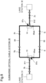
- Fig. 9 is a conceptual diagram illustrating a configuration example of a section relating to optical transmission in the submarine optical cable system 50 in Fig. 8 .
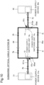
- Fig. 10 is a conceptual diagram illustrating a power supply system in the submarine optical cable system 50 in Fig. 8 . It is assumed that the contents of those drawings can be analogized and understood from the explanation given above, and hence explanation therefor is omitted while avoiding complexity.
- Fig. 11 is a conceptual diagram illustrating a state in which a failure occurs in the submarine optical cable system 50 in Fig. 8 .
- the branch device 13 connects the optical fiber pairs of the submarine optical cable 811 to optical fiber pairs of the submarine optical cable 85. Further, the branch device 13 connects the power supply wire of the submarine optical cable 811 to the power supply wire of the submarine optical cable 85. Further, the branch device 14 connects the optical fiber pairs of the submarine optical cable 812 to the optical fiber pairs of the submarine optical cable 85. Further, the branch device 14 connects the power supply wire of the submarine optical cable 812 to the power supply wire of the submarine optical cable 85.
- the land stations 31 and 32 are capable of establishing optical communication with each other by using the submarine optical cable 85.
- Fig. 12 is a conceptual diagram illustrating the submarine optical cable system 50 in which the configuration for establishing connection with another land station is additionally installed in the additional installation scheduled section 91 in Fig. 4 .
- An additional installation section 92 being a section that is additionally installed includes submarine optical cables 85 and 86, a branch device 15, relay amplification devices 2i to 2k, and the land station 35.
- the branch device 15 connects some or all of the optical fiber pairs included in the submarine optical cable 85 to the optical fiber pairs included in the submarine optical cable 86.
- the branch device 15 includes an optical switch for switching the connection.
- the optical switch follows the optical connection switching information that is transmitted from any one of the land stations 31, 32, and 35, and performs switching of the connection of the optical fiber pairs between the submarine optical cables.
- the above-mentioned method of transmitting the control information from the land station 31 to the branch device 13 is applicable to the method of transmitting the optical connection switching information from the land station 31, 32, or 35.
- the branch device 15 further includes a connection switching unit (electrical switch).
- the connection switching unit switches connection destinations of a power supply wire included in the submarine optical cable 86, based on the above-mentioned control information.
- the submarine optical cable system 50 in Fig. 12 is capable of establishing optical communication of the land station 35 with both or one of the land stations 31 and 32.
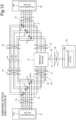
- Fig. 13 is conceptual diagram illustrating a section relating to transmission of an optical signal in the submarine optical cable system 50 in Fig. 12 .
- the branch device 15 connects any one pair of the optical fiber pairs 77 to 79 to the optical fiber pairs 7d included in the submarine optical cable 86 that is connected to a transmission device 35b included in the land station 35.
- the transmission device 35b enables optical communication with one or both of the transmission devices 31b and 32b.
- the branch device 15 connects any freely selected one of the optical fiber pairs 77 to 79 to the optical fiber pair 7d. Further, an internal configuration of the branch device 15 for establishing the connection is freely selected. Moreover, the branch device 15 may be configured in such a manner that the submarine optical cable 86 includes optical fiber pairs other than the optical fiber pair 7d and that each of them is connected to any one of the optical fiber pairs 77 to 79.
- Fig. 14 is a conceptual diagram illustrating a section relating to power supply in the submarine optical cable system 50 in Fig. 12 .
- a power supply switching unit 15a included in the branch device 15 connects a power supply wire 85a supplied with power from a power supply device 35a included in the land station 35, to a power supply wire 86a included in the submarine optical cable 86 in Fig. 12 .
- the power supply switching unit 15a may be omitted.
- the configurations of the branch device 15, the submarine optical cable 86, and the land station 35 are highly flexible.
- the submarine optical cable system 50 in Fig. 4 enables such additional installation in a highly flexible manner without interrupting large-capacity optical communication between the land station 31 and the land station 32.
- the submarine optical cable system according to the present example embodiment enables additional installation that provides a communication path between the two branch devices with a redundancy configuration.
- communication can be established by using another communication path by, first, performing additional installation that provides the redundancy configuration between those branch devices.
- the submarine optical cable system when additional installation is performed for establishing optical communication with another land station in the section between those branch devices, the submarine optical cable system enables additional installation of a configuration for establishing optical communication with another land station in another communication path while maintaining optical communication between the existing land stations in the one communication path.
- the submarine optical cable system enables a higher degree of flexibility of configurations to be additionally installed in order to establish optical communication with another land station.
- Fig. 15 is a conceptual diagram illustrating a configuration of a submarine optical cable system 50x being a minimum configuration of a submarine optical cable system according to an example embodiment.
- the submarine optical cable system 50x includes a first switching device 13x, a second switching device 14x, and a third submarine optical cable 84x.
- the first switching device 13x is connected to a first land station via a first submarine optical cable.
- the second switching device 14x is connected to a second land station via a second submarine optical cable.
- the third submarine optical cable 84x is connected to the first switching device 13x and the second switching device 14x.
- the first switching device 13x includes a first optical fiber core connecting unit to which an optical fiber core of a submarine optical cable associated with the third submarine optical cable 84x is allowed to be connected.
- the first switching device 13x further includes a first optical switch group that switches a connection destination of an optical fiber core included in the first submarine optical cable, to any one of an optical fiber core included in the third submarine optical cable 84x and the first optical fiber core connecting unit, based on first optical connection switching information being transmitted.
- the second switching device 14x includes a second optical fiber core connecting unit to which an optical fiber core of a submarine optical cable associated with the third submarine optical cable 84x is allowed to be connected.
- the second switching device 14x further includes a second optical switch group that switches a connection destination of an optical fiber core included in the second submarine optical cable, based on second optical connection switching information being transmitted.
- the second switch group switches the connection destination to any one of an optical fiber core included in the third submarine optical cable 84x and the second optical fiber core connecting unit.
- the submarine optical cable system 50x enables additional installation in such a way that the communication path between the first switching device 13x and the second switching device 14x is redundantly configured.
- the submarine optical cable system 50x further enables additional installation in such a way that optical communication is established between another land station and at least one of the first land station and the second land station while maintaining optical communication between the first land station and the second land station.
- the submarine optical cable system 50x enables additional installation without interrupting optical communication between the first land station and the second land station, and therefore, is able to secure the degree of flexibility of configurations to be additionally installed in such a way as to establish optical communication with another land station.
- the submarine optical cable system 50x improves the degree of flexibility of configurations to be additionally installed.
- the submarine optical cable system 50x exerts the effects described in the section [Advantageous Effects of Invention] with the configuration mentioned above.
- a submarine optical cable system including:
- the submarine optical cable system according to supplementary note 1, wherein the first optical fiber core connecting unit is present inside a casing of the first switching device, and the second optical fiber core connecting unit is present inside a casing of the second switching device.
- the submarine optical cable system according to supplementary note 1 or 2, wherein the first optical fiber core connecting unit and the second optical fiber core connecting unit are protected.
- the submarine optical cable system according to any one of supplementary notes 1 to 3, wherein the first optical connection switching information and the second optical connection switching information are transmitted from any one of the first land station and the second land station.
- the submarine optical cable system according to supplementary note 7, wherein the first power supply wire connecting unit is present inside a casing of the first switching device, and the second power supply wire connecting unit is present inside a casing of the second switching device.
- the submarine optical cable system according to supplementary note 7 or 8, wherein the first power supply wire connecting unit and the second power supply wire connecting unit are protected.
- the submarine optical cable system according to any one of supplementary notes 7 to 9, wherein the first power supply switching information and the second power supply switching information are transmitted from any one of the first land station and the second land station.
- the submarine optical cable system according to any one of supplementary notes 1 to 12, further including at least one of the first submarine optical cable and the second submarine optical cable.
- the submarine optical cable system according to any one of supplementary notes 1 to 13, further including at least one of the first land station and the second land station.
- the first land station is associated with, for example, the land station 31 in Fig. 4 , 5 , or 7 .
- the first submarine optical cable is associated with, for example, the submarine optical cable 811 in Fig. 4 or 5 .
- the first switching device is associated with, for example, the branch device 13 in Fig. 4 , 5 , or 7 or the first switching device 13x in Fig. 15 .
- the second land station is associated with, for example, the land station 32 in Fig. 4 , 5 , or 7 .
- the second submarine optical cable is associated with, for example, the submarine optical cable 812 in Fig. 4 or 5 .
- the second switching device is associated with, for example, the branch device 14 in Fig. 4 , 5 , or 7 or the second switching device 14x in Fig. 15 .
- the third submarine optical cable is associated with, for example, the submarine optical cable 84 in Fig. 4 or 5 or the third submarine optical cable 84x in Fig. 15 .
- the first optical fiber core connecting unit is associated with, for example, the opened end of the optical fiber pair group 61 in Fig. 5 or 6 .
- the first optical connection switching information is associated with, for example, the connection switching information contained in the control information received by the reception unit 13c in Fig. 6 .
- the first optical switch group is associated with, for example, the optical switch group including the optical switch pairs 1 to 3 in Fig. 6 .
- the second optical fiber core connecting unit is associated with, for example, the opened end of the optical fiber pair group 62 in Fig. 5 .
- the second optical connection switching information is associated with, for example, the connection switching information contained in the control information received by the reception unit, which is included in the "second switching device", associated with the reception unit 13c in Fig. 6 .
- the second optical switch group is associated with, for example, the optical switch group including the optical switch pairs, which is included in “the second switching device", associated with the optical switch pairs 1 to 3 in Fig. 6 .
- the submarine optical cable system is associated with, for example, the submarine optical cable system 50 in Fig. 4 , 5 , or 7 or the submarine optical cable system 50x in Fig. 15 .
- the first power supply wire connecting unit is associated with, for example, the power supply terminal 85aa in Fig. 7 .
- the first power supply switching information is associated with, for example, the power supply switching information contained in the control information received by the reception unit 13c in Fig. 6 .
- the first electrical switch is associated with, for example, the power supply switching unit 13a in Fig. 7 .
- the second power supply wire connecting unit is associated with, for example, a power supply terminal 85ab in Fig. 7 .
- the second power supply switching information is associated with, for example, the power supply switching information contained in the control information received by the reception unit, which is included in the branch device 14 in Fig. 7 , associated with the reception unit 13c in Fig. 6 .
- the second electrical switch is associated with, for example, the power supply switching unit 14a in Fig. 7 .
Landscapes
- Engineering & Computer Science (AREA)
- Computer Networks & Wireless Communication (AREA)
- Physics & Mathematics (AREA)
- Electromagnetism (AREA)
- Signal Processing (AREA)
- Computing Systems (AREA)
- Optical Communication System (AREA)
- Cable Transmission Systems, Equalization Of Radio And Reduction Of Echo (AREA)
Abstract
Description
- The present invention relates to communication via a submarine optical cable.
- A submarine optical cable system that establishes optical communication between land stations has been widely used for intercontinental and large-capacity communication or the like.
-
Fig. 1 is a conceptual diagram illustrating a configuration of a submarineoptical cable system 50 being an example of a general submarine optical cable system. The submarineoptical cable system 50 includesland stations 31 to 34,relay amplification devices 2a to 2f,branch devices optical cables 81 to 83. - The submarine
optical cables 81 to 83 are submarine optical cables that are installed mainly on the seabed or in the sea water. The submarineoptical cables 81 to 83 each include an optical fiber pair and a power supply wire. Herein, the optical fiber pair is a pair of optical fiber cores through which optical signals advance in directions opposite to each other. Further, the power supply wire is a lead wire for supplying power to the branch device, the relay amplification device, and the like that are connected to the submarine optical cable. - The
land stations 31 to 34 are installed on the land, and each transmit an optical signal to another land station and receive an optical signal to be transmitted from another land station. Each of theland stations 31 to 34 further supplies power to the power supply wire included in the connected submarine optical cable. - The
relay amplification devices 2a to 2f each optically amplify optical signals in both directions that are transmitted via the optical fiber pair included in the inserted submarine optical cable. Therelay amplification devices 2a to 2f are installed on the seabed or in the sea water. Those matters are similar with regard to other relay amplification devices to be described later as well. - The
branch devices branch device 11 connects the submarineoptical cable 81 and the submarineoptical cable 82 to each other. The connection includes connection of the optical fiber pair included in the submarineoptical cable 81 to the optical fiber pair included in the submarineoptical cable 82, and connection of the power supply wire included in the submarineoptical cable 81 to the power supply wire included in the submarineoptical cable 82. - The
branch device 12 connects the submarineoptical cable 81 and the submarineoptical cable 83 to each other. The connection includes connection (branching) of the optical fiber pair included in the submarineoptical cable 81 to the optical fiber pair included in the submarineoptical cable 83, and connection (branching) of the power supply wire included in the submarineoptical cable 81 to the power supply wire included in the submarineoptical cable 83. - With the configuration described above, the submarine
optical cable system 50 enables optical communication among theland stations 31 to 34. - In actuality, the
branch devices -
Fig. 2 is a conceptual diagram illustrating a state in which a failure occurs in the submarineoptical cable system 50 inFig. 1 . Due to a failure at a position A, a communication path between thebranch device 11 and thebranch device 12 cannot be used. Thus, optical communication with a huge amount of traffic cannot be established between theland station 31 and theland station 32. This situation continues until recovery from the failure of the submarineoptical cable 81. In this manner, when a failure occurs in the submarine optical cable, optical communication via the submarine optical cable cannot be established until recovery is made by replacing the submarine optical cable or the like. - Herein,
PTL 1 discloses an optical cable system including a redundancy optical cable that has one end connected to an optical branch device and has first and second elongated branch optical fiber pairs being built-in. - Further,
PTL 2 discloses a branch device that includes a standby circuit system, includes a cable branched into a plurality of directions, and is capable of performing switching from an active system having a failure to the standby circuit system when the failure occurs. -
- [PTL 1]
Japanese Unexamined Patent Application Publication No. H07-087013 - [PTL 2]
Japanese Unexamined Patent Application Publication No. H04-137828 - A general submarine optical cable system has a problem that arises when facilities for optically communicating with other land stations are scheduled to be additionally installed in the future. This is because, when a branch device, a submarine optical cable, and the like are scheduled to be additionally installed in the future for connection with other land stations, a configuration of the facilities to be additionally installed is required to be determined from the beginning.
- For example, as illustrated in (a) of
Fig. 3 , it is assumed that a configuration to be connected with aland station 35 is scheduled to be additionally installed in the submarineoptical cable system 50 in the future. In the submarineoptical cable system 50 in (a) ofFig. 3 , therelay amplification devices branch devices land stations optical cables Fig. 1 are not illustrated. - In this case, a
branch device 13 is required to be installed in advance before additional installation. This is because, in order to perform additional installation afterward, huge-traffic optical communication is required to be stopped between theland stations branch device 13 is configured by a one-by-two switch as illustrated in (b) ofFig. 3 , it is impossible in actuality to change the configuration to a two-by-two switch as illustrated in (c) ofFig. 3 . Thus, there is a limitation also to a degree of flexibility in selecting which optical fiber core included in the submarineoptical cable 81 is to be connected to an optical fiber core included in a submarine optical cable for establishing connection with theland station 35. - An object of the present invention is to provide a submarine optical cable system and the like that improve a degree of flexibility of a configuration to be additionally installed.
- A submarine optical cable system according to the present invention includes a first switching device being connected to a first land station via a first submarine optical cable, a second switching device being connected to a second land station via a second submarine optical cable, and a third submarine optical cable being connected to the first switching device and the second switching device, wherein the first switching device includes a first optical fiber core connecting unit to which an optical fiber core of a submarine optical cable equivalent to the third submarine optical cable is allowed to be connected, and a first optical switch group that switches a connection destination of an optical fiber core included in the first submarine optical cable to any one of an optical fiber core included in the third submarine optical cable and the first optical fiber core connecting unit, based on first optical connection switching information being transmitted, and the second switching device includes a second optical fiber core connecting unit to which an optical fiber core of a submarine optical cable equivalent to the third submarine optical cable is allowed to be connected, and a second optical switch group that switches a connection destination of an optical fiber core included in the second submarine optical cable to any one of an optical fiber core included in the third submarine optical cable and the second optical fiber core connecting unit, based on second optical connection switching information being transmitted.
- The submarine optical cable system and the like according to the present invention improve a degree of flexibility of a configuration to be additionally installed.
-
- [
Fig. 1] Fig. 1 is a conceptual diagram illustrating a configuration example of a general submarine optical cable system. - [
Fig. 2] Fig. 2 is a conceptual diagram illustrating a state in which a failure occurs in the general submarine optical cable system. - [
Fig. 3] Fig. 3 is a conceptual diagram illustrating an example in which additional installation is enabled in the general submarine optical cable system. - [
Fig. 4] Fig. 4 is a conceptual diagram illustrating a configuration example of a submarine optical cable system according to the present example embodiment. - [
Fig. 5] Fig. 5 is a conceptual diagram illustrating an example of a section relating to transmission of an optical signal in the submarine optical cable system according to the present example embodiment. - [
Fig. 6] Fig. 6 is a conceptual diagram illustrating a configuration example of a branch device according to the present example embodiment. - [
Fig. 7] Fig. 7 is a conceptual diagram illustrating a configuration example of a section relating to power supply in the submarine optical cable system according to the present example embodiment. - [
Fig. 8] Fig. 8 is a conceptual diagram illustrating a configuration example of the submarine optical cable system that is redundantly configured by additionally installing an additional installation scheduled section. - [
Fig. 9] Fig. 9 is a conceptual diagram illustrating a configuration example of a section relating to optical transmission in the submarine optical cable system that is redundantly configured by additionally installing the additional installation scheduled section. - [
Fig. 10] Fig. 10 is a conceptual diagram illustrating a configuration example of a section relating to power supply in the submarine optical cable system that is redundantly configured by additionally installing the additional installation scheduled section. - [
Fig. 11] Fig. 11 is a conceptual diagram illustrating a state in which a failure occurs in the submarine optical cable system that is redundantly configured by additionally installing the additional installation scheduled section. - [
Fig. 12] Fig. 12 is a conceptual diagram illustrating a configuration example of the submarine optical cable system in which a configuration for establishing optical communication with another land station is additionally installed in the additional installation scheduled section. - [
Fig. 13] Fig. 13 is a conceptual diagram illustrating a configuration example of a section relating to optical transmission in the submarine optical cable system in which a configuration for establishing optical communication with another land station is additionally installed in the additional installation scheduled section. - [
Fig. 14] Fig. 14 is a conceptual diagram illustrating a configuration example of a section relating to power supply in the submarine optical cable system in which a configuration for establishing optical communication with another land station is additionally installed in the additional installation scheduled section. - [
Fig. 15] Fig. 15 is a conceptual diagram illustrating a minimum configuration of a submarine optical cable system according to an example embodiment. -
Fig. 4 is a conceptual diagram illustrating a configuration of a submarineoptical cable system 50 being an example of a submarine optical cable system according to the present example embodiment. An additional installation scheduledsection 91 is a section in which additional installation is scheduled. - In the submarine
optical cable system 50 inFig. 4 , abranch device 13 is connected to a submarineoptical cable 811, and abranch device 14 is connected to a submarineoptical cable 812. Thebranch device 13 and thebranch device 14 are connected to each other via a submarineoptical cable 84. The connection therebetween involves optical connection using optical fiber pairs and electrical connection using power supply wires. Herein, the optical fiber pair is a pair of optical fiber cores through which optical signals advance in directions opposite to each other. The number of optical fiber pairs included in the submarineoptical cable 84 is, for example, equal to the number of optical fiber pairs included in the submarineoptical cable - The
branch device 13 causes optical signals that are transmitted from theland station 31 via the optical fiber pairs of the submarineoptical cable 811, to enter the optical fiber pairs included in the submarineoptical cable 84. Note that, when the additional installation scheduledsection 91 is additionally installed, thebranch device 13 is also capable of distributing the optical signals to optical fiber pairs included in a submarine optical cable included in the additionally installed section. - The
branch device 13 further causes optical signals that are transmitted from theland station 32 via the optical fiber pairs of the submarineoptical cable 84, to enter the optical fiber pairs included in the submarineoptical cable 811. Note that, when the additional installation scheduledsection 91 is additionally installed, thebranch device 13 is also capable of causing the optical signals that are transmitted from the optical fiber pairs included in the submarine optical cable included in the additionally installed section, to enter the optical fiber pair of the submarineoptical cable 811. - The
branch device 13 includes an optical switch that performs switching the entry of optical signals described above. For example, the optical switch performs switching of the optical fiber core being a connection destination, based on optical connection switching information that is transmitted from theland station 31 via the optical fiber cores of the submarineoptical cable 811. The optical connection information described above may be transmitted from theland station 32 via the optical fiber cores of the submarineoptical cable 84. - The
branch device 13 further connects the power supply wire included in the submarineoptical cable 811 to the power supply wire included in the submarineoptical cable 84. Note that, when the additional installation scheduledsection 91 is additionally installed, thebranch device 13 is also capable of connecting the power supply wire of the submarineoptical cable 811 to the power supply wire included in the submarine optical cable included in the additionally installed section. - The
branch device 13 includes a connection switching unit (electrical switch) for performing such connection switching. For example, the connection switching unit performs switching of the power supply wire being a connection destination, based on power supply switching information that is transmitted from theland station 31 via the optical fiber cores of the submarineoptical cable 811. The power supply switching information may be transmitted from theland station 32 via the optical fiber core of the submarineoptical cable 84. - The
branch device 14 has a configuration similar to thebranch device 13, and performs similar operations. - In other words, the
branch device 14 causes optical signals that are transmitted from theland station 32 vis the optical fiber pairs of the submarineoptical cable 812, to enter the optical fiber pairs included in the submarineoptical cable 84. Note that, when the additional installation scheduledsection 91 is additionally installed, thebranch device 14 is also capable of distributing the optical signals that are transmitted from theland station 32 via the optical fiber pairs of the submarineoptical cable 812, to the optical fiber pairs included in the submarine optical cable included in the additionally installed section. - The
branch device 14 further causes optical signals that are transmitted from theland station 31 via the optical fiber pair of the submarineoptical cable 84, to enter the optical fiber pair included in the submarineoptical cable 812. Note that, when the additional installation scheduledsection 91 is additionally installed, thebranch device 14 is also capable of causing the optical signals that are transmitted via the optical fiber pair included in the submarine optical cable included in the additionally installed section, to enter the optical fiber pair of the submarineoptical cable 812. - The
branch device 14 includes an optical switch that performs switching of the optical signals described above. For example, the optical switch performs switching of the optical fiber core being a connection destination, based on optical connection switching information that is transmitted from theland station 32 via the optical fiber cores of the submarineoptical cable 812. The optical connection switching information may be transmitted from theland station 31 via the optical fiber cores of the submarineoptical cable 84. - The
branch device 14 further connects the power supply wire included in the submarineoptical cable 812 to the power supply wire included in the submarineoptical cable 84. Note that, when the additional installation scheduledsection 91 is additionally installed, thebranch device 14 is also capable of connecting the power supply wire of the submarineoptical cable 812 to a power supply wire included in the submarine optical cable included in the additionally installed section. - The
branch device 14 includes a connection switching unit (electrical switch) for performing such connection switching. For example, the connection switching unit performs switching of the power supply wire being a connection destination, based on power supply switching information that is transmitted from theland station 32 via the optical fiber cores of the submarineoptical cable 812. Alternatively, the power supply switching information may be transmitted from theland station 31 via the optical fiber cores of the submarineoptical cable 84. -
Fig. 5 is a conceptual diagram illustrating a configuration example of a section relating to transmission of an optical signal in the submarineoptical cable system 50 inFig. 4 . Further,Fig. 6 is a conceptual diagram illustrating a configuration example of thebranch device 13 inFig. 5 . - The
land stations transmission devices optical cable 811 includes optical fiber pairs 71 to 73. The submarineoptical cable 812 includes optical fiber pairs 7a to 7c. The submarineoptical cable 84 includes optical fiber pairs 74 to 76. - The
branch device 13 includes optical switch pairs 1 to 3, a reception unit 13c, and acontrol unit 13b. To the reception unit 13c, an optical signal that is extracted by acoupler 51 from a lower optical fiber core of theoptical fiber pair 73. The optical signal is an optical signal that is transmitted from thetransmission device 31b inFig. 5 to thetransmission device 32b, and a control signal destined for thebranch device 13 may be superimposed with the optical signal in some cases. - The reception unit 13c receives control information destined for the
branch device 13, and transmits the received signal to thecontrol unit 13b. When the control signal contains the optical connection switching information for switching the connection destination of the optical switch pairs 1 to 3, thecontrol unit 13b follows the optical connection switching information. In other words, thecontrol unit 13b follows the optical connection switching information, and causes each of the optical switch pairs 1 to 3 to switch a connection destination of each of the optical fiber pairs 71 to 73 to each of the optical fiber pairs 74 to 74 or each of the optical fiber pairs 77 to 79. The optical fiber pairs 77 to 79 are optical fiber pairs constituting an opticalfiber pair group 61. - The
branch device 14 inFig. 5 is also similar thereto. - Note that, in
Figs. 5 and6 , for convenience of the explanation, the number of optical fiber pairs included in one submarine optical cable is three pairs, and the number of optical fiber pairs included in one submarine optical cable is freely selected. In general, the number of optical fiber pairs included in one submarine optical cable is four or more pairs. - In the submarine
optical cable system 50 inFigs. 5 and6 , the optical switch pairs 1 to 3 of thebranch device 13 connect the optical fiber pairs 71 to 73 to the optical fiber pairs 74 to 76. Further, an end of each optical fiber pair in the opticalfiber pair group 61 including optical fiber pairs that are not connected to any of the optical fiber pairs 71 to 73 and the optical fiber pairs 74 to 76 is opened. When additional installation is performed afterward, the opticalfiber pair group 61 is drawn out by an optical cable to the outside of thebranch device 13 in such a way as to be connected to optical fiber pairs of a submarine optical cable for additional installation, and an end thereof is accommodated in a casing for connection. Inside the casing for connection, each optical fiber is subjected to an end terminating process in such a way as to prevent reflection at an end surface, and the end is opened. - The
branch device 14 is also similar thereto. -
Fig. 7 is a conceptual diagram illustrating a section relating to power supply in the submarineoptical cable system 50 inFig. 4 . Theland stations power supply devices 31a and 32a.Power supply wires optical cables Fig. 4 . The power supply wires are power wires (lead wires) for supplying power from thepower supply devices branch devices supply switching units - The power
supply switching unit 13a connects thepower supply wire 811a to thepower supply wire 84a. Note that, when the additional installation scheduledsection 91 inFig. 4 is additionally installed, the powersupply switching unit 13a follows the power supply switching information contained in the control information transmitted from theland station supply switching unit 13a follows the power supply switching information, and a power supply wire included in a submarine optical cable in an additionally installed section in actuality, which is associated with the additional installation scheduledsection 91, is switched to the connection destination of thepower supply wire 811a. For example, theland station branch device 13 via any one of the optical fiber pairs connected to thebranch device 13. A method of transmitting the power supply switching information is similar to the above-mentioned method of transmitting the optical connection switching information that is transmitted for switching the optical switch pairs. For example, the reception unit 13c inFig. 6 may receive the power supply switching information, and thecontrol unit 13b may switch the powersupply switching unit 13a inFig. 7 , based on the power supply switching information. - The power
supply switching unit 14a is also similar to the powersupply switching unit 13a. - In the submarine
optical cable system 50 inFig. 7 , a power supply terminal 85aa that is not connected to any one of thepower supply wires branch device 13, and is protected in such a way as to be connected to a power supply wire of the submarine optical cable for additional installation when additional installation is performed afterward. The power supply terminal 85aa is grounded by connecting, in thebranch device 13, the power supply wire connected to the power supply terminal 85aa to aground 87a. For example, theground 87a is a sea ground. - The
branch device 14 is also similar thereto. - There are mainly following two ways of performing additional installation in the additional installation scheduled
section 91 inFig. 4 . In one method, the additional installation scheduledsection 91 is configured similarly to a configuration including the submarineoptical cable 84 andrelay amplification devices section 91. - First, explanation is made on a case of a redundancy configuration.
Fig. 8 is a conceptual diagram illustrating the submarineoptical cable system 50 that is redundantly configured by additionally installing the additional installation scheduledsection 91 inFig. 4 . - The
branch device 13 inFig. 8 is capable of distributing the optical signals that are transmitted from theland station 31 via the optical fiber pairs of the submarineoptical cable 811, to the optical fiber pairs included in the submarineoptical cable 84 and optical fiber pairs included in a submarineoptical cable 85. Thebranch device 13 is also capable of distributing the optical signals that are transmitted via the optical fiber pairs of the submarineoptical cable 811, to any one of the optical fiber pairs included in the submarineoptical cable 84 and optical fiber pairs included in the submarineoptical cable 85. - The
branch device 13 is further capable of causing the optical signals that are transmitted from theland station 32 via the optical fiber pairs of the submarineoptical cables optical cable 811. - In the state of
Fig. 8 , thebranch device 13 connects the power supply wire included in the submarineoptical cable 811 to the power supply wire included in the submarineoptical cable 84. A right end of the power supply wire included in the submarineoptical cable 84 is connected to aground 87c by thebranch device 14. With this, an electric current flows from the power supply device included in theland station 31 to theground 87c, and power is supplied to the submarineoptical cables - In the state of
Fig. 8 , thebranch device 14 connects the power supply wire included in the submarineoptical cable 812 on the left, to a power supply wire included in the submarineoptical cable 85. The left end of the power supply wire included in the submarineoptical cable 85 is connected to theground 87a by thebranch device 13. With this, an electric current flows from the power supply device included in theland station 32 to theground 87c, and power is supplied to the submarineoptical cables - The
branch device 13 is capable of switching the connection destination of the power supply wire included in the submarineoptical cable 811 from the state ofFig. 8 to the power supply wire included in the submarineoptical cable 85. Further, thebranch device 14 is capable of switching the connection destination of the power supply wire included in the submarineoptical cable 812 from the state ofFig. 8 to the power supply wire included in the submarineoptical cable 84. In this manner, the submarine optical cable system inFig. 8 is redundantly configured in a section between thebranch device 13 and thebranch device 14. -
Fig. 9 is a conceptual diagram illustrating a configuration example of a section relating to optical transmission in the submarineoptical cable system 50 inFig. 8 . Further,Fig. 10 is a conceptual diagram illustrating a power supply system in the submarineoptical cable system 50 inFig. 8 . It is assumed that the contents of those drawings can be analogized and understood from the explanation given above, and hence explanation therefor is omitted while avoiding complexity. -
Fig. 11 is a conceptual diagram illustrating a state in which a failure occurs in the submarineoptical cable system 50 inFig. 8 . In the submarineoptical cable system 50 inFig. 11 , thebranch device 13 connects the optical fiber pairs of the submarineoptical cable 811 to optical fiber pairs of the submarineoptical cable 85. Further, thebranch device 13 connects the power supply wire of the submarineoptical cable 811 to the power supply wire of the submarineoptical cable 85. Further, thebranch device 14 connects the optical fiber pairs of the submarineoptical cable 812 to the optical fiber pairs of the submarineoptical cable 85. Further, thebranch device 14 connects the power supply wire of the submarineoptical cable 812 to the power supply wire of the submarineoptical cable 85. - As described above, even when a failure occurs at a position A of the submarine
optical cable 84, theland stations optical cable 85. - Next, explanation is made on a case in which a configuration enabling optical communication with another land station is additionally installed in the additional installation scheduled
section 91 inFig. 4 . -
Fig. 12 is a conceptual diagram illustrating the submarineoptical cable system 50 in which the configuration for establishing connection with another land station is additionally installed in the additional installation scheduledsection 91 inFig. 4 . Anadditional installation section 92 being a section that is additionally installed includes submarineoptical cables branch device 15,relay amplification devices 2i to 2k, and theland station 35. - The
branch device 15 connects some or all of the optical fiber pairs included in the submarineoptical cable 85 to the optical fiber pairs included in the submarineoptical cable 86. Thebranch device 15 includes an optical switch for switching the connection. The optical switch follows the optical connection switching information that is transmitted from any one of theland stations land station 31 to thebranch device 13 is applicable to the method of transmitting the optical connection switching information from theland station - The
branch device 15 further includes a connection switching unit (electrical switch). The connection switching unit switches connection destinations of a power supply wire included in the submarineoptical cable 86, based on the above-mentioned control information. - With the configuration described above, the submarine
optical cable system 50 inFig. 12 is capable of establishing optical communication of theland station 35 with both or one of theland stations -
Fig. 13 is conceptual diagram illustrating a section relating to transmission of an optical signal in the submarineoptical cable system 50 inFig. 12 . InFig. 13 , thebranch device 15 connects any one pair of the optical fiber pairs 77 to 79 to theoptical fiber pairs 7d included in the submarineoptical cable 86 that is connected to atransmission device 35b included in theland station 35. With this, thetransmission device 35b enables optical communication with one or both of thetransmission devices - The
branch device 15 connects any freely selected one of the optical fiber pairs 77 to 79 to theoptical fiber pair 7d. Further, an internal configuration of thebranch device 15 for establishing the connection is freely selected. Moreover, thebranch device 15 may be configured in such a manner that the submarineoptical cable 86 includes optical fiber pairs other than theoptical fiber pair 7d and that each of them is connected to any one of the optical fiber pairs 77 to 79. -
Fig. 14 is a conceptual diagram illustrating a section relating to power supply in the submarineoptical cable system 50 inFig. 12 . InFig. 14 , a powersupply switching unit 15a included in thebranch device 15 connects apower supply wire 85a supplied with power from a power supply device 35a included in theland station 35, to apower supply wire 86a included in the submarineoptical cable 86 inFig. 12 . - Note that there may be adopted a configuration in which the
power supply wire 86a is not connected to thepower supply wire 85a. In such a case, the powersupply switching unit 15a may be omitted. - As understood from the explanation given above, the configurations of the
branch device 15, the submarineoptical cable 86, and theland station 35 are highly flexible. The submarineoptical cable system 50 inFig. 4 enables such additional installation in a highly flexible manner without interrupting large-capacity optical communication between theland station 31 and theland station 32. - In this manner, in the submarine
optical cable system 50 before additional installation, which is illustrated inFig. 4 , with regard to the configuration of the additional installation scheduledsection 91, a high degree of flexibility in design is secured, as compared to the general submarineoptical cable system 50 illustrated inFig. 3 . - The submarine optical cable system according to the present example embodiment enables additional installation that provides a communication path between the two branch devices with a redundancy configuration. Thus, even when a failure occurs in one communication path, communication can be established by using another communication path by, first, performing additional installation that provides the redundancy configuration between those branch devices.
- Moreover, when additional installation is performed for establishing optical communication with another land station in the section between those branch devices, the submarine optical cable system enables additional installation of a configuration for establishing optical communication with another land station in another communication path while maintaining optical communication between the existing land stations in the one communication path. Thus, the submarine optical cable system enables a higher degree of flexibility of configurations to be additionally installed in order to establish optical communication with another land station.
-
Fig. 15 is a conceptual diagram illustrating a configuration of a submarineoptical cable system 50x being a minimum configuration of a submarine optical cable system according to an example embodiment. The submarineoptical cable system 50x includes afirst switching device 13x, asecond switching device 14x, and a third submarineoptical cable 84x. Thefirst switching device 13x is connected to a first land station via a first submarine optical cable. Thesecond switching device 14x is connected to a second land station via a second submarine optical cable. The third submarineoptical cable 84x is connected to thefirst switching device 13x and thesecond switching device 14x. - The
first switching device 13x includes a first optical fiber core connecting unit to which an optical fiber core of a submarine optical cable associated with the third submarineoptical cable 84x is allowed to be connected. Thefirst switching device 13x further includes a first optical switch group that switches a connection destination of an optical fiber core included in the first submarine optical cable, to any one of an optical fiber core included in the third submarineoptical cable 84x and the first optical fiber core connecting unit, based on first optical connection switching information being transmitted. - The
second switching device 14x includes a second optical fiber core connecting unit to which an optical fiber core of a submarine optical cable associated with the third submarineoptical cable 84x is allowed to be connected. Thesecond switching device 14x further includes a second optical switch group that switches a connection destination of an optical fiber core included in the second submarine optical cable, based on second optical connection switching information being transmitted. The second switch group switches the connection destination to any one of an optical fiber core included in the third submarineoptical cable 84x and the second optical fiber core connecting unit. - With the configuration described above, the submarine
optical cable system 50x enables additional installation in such a way that the communication path between thefirst switching device 13x and thesecond switching device 14x is redundantly configured. With the configuration described above, the submarineoptical cable system 50x further enables additional installation in such a way that optical communication is established between another land station and at least one of the first land station and the second land station while maintaining optical communication between the first land station and the second land station. Moreover, the submarineoptical cable system 50x enables additional installation without interrupting optical communication between the first land station and the second land station, and therefore, is able to secure the degree of flexibility of configurations to be additionally installed in such a way as to establish optical communication with another land station. - As described above, the submarine
optical cable system 50x improves the degree of flexibility of configurations to be additionally installed. Thus, the submarineoptical cable system 50x exerts the effects described in the section [Advantageous Effects of Invention] with the configuration mentioned above. - The above has been an explanation made on the example embodiments of the present invention, but the present invention is not limited to the above-mentioned example embodiments, and further modifications, replacement, and adjustment can be added without departing from the basic technical idea of the present invention. For example, the configurations of the elements illustrated in the drawings are merely examples for easy understanding of the present invention, and are not limited to the configurations illustrated in the drawings.
- The whole or part of the example embodiments disclosed above can be described as, but not limited to, the following supplementary notes.
- A submarine optical cable system including:
- a first switching device being connected to a first land station via a first submarine optical cable;
- a second switching device being connected to a second land station via a second submarine optical cable; and
- a third submarine optical cable being connected to the first switching device and the second switching device, wherein
- the first switching device includes:
- a first optical fiber core connecting unit to which an optical fiber core of a submarine optical cable equivalent to the third submarine optical cable is allowed to be connected; and
- a first optical switch group that switches a connection destination of an optical fiber core included in the first submarine optical cable to any one of an optical fiber core included in the third submarine optical cable and the first optical fiber core connecting unit, based on first optical connection switching information being transmitted, and
- the second switching device includes:
- a second optical fiber core connecting unit to which an optical fiber core of a submarine optical cable equivalent to the third submarine optical cable is allowed to be connected; and
- a second optical switch group that switches a connection destination of an optical fiber core included in the second submarine optical cable to any one of an optical fiber core included in the third submarine optical cable and the second optical fiber core connecting unit, based on second optical connection switching information being transmitted.
- The submarine optical cable system according to
supplementary note 1, wherein
the first optical fiber core connecting unit is present inside a casing of the first switching device, and the second optical fiber core connecting unit is present inside a casing of the second switching device. - The submarine optical cable system according to
supplementary note
the first optical fiber core connecting unit and the second optical fiber core connecting unit are protected. - The submarine optical cable system according to any one of
supplementary notes 1 to 3, wherein
the first optical connection switching information and the second optical connection switching information are transmitted from any one of the first land station and the second land station. - The submarine optical cable system according to any one of
supplementary notes 1 to 4, wherein - the first optical connection switching information is transmitted via the first submarine optical cable or the third submarine optical cable, and
- the second optical connection switching information is transmitted via the second submarine optical cable or the third submarine optical cable.
- The submarine optical cable system according to
supplementary note 5, wherein - the first optical connection switching information is transmitted via an optical fiber core included in the first submarine optical cable or the third submarine optical cable, and
- the second optical connection switching information is transmitted via an optical fiber core included in the second submarine optical cable or the third submarine optical cable.
- The submarine optical cable system according to any one of
supplementary notes 1 to 6, wherein - the first switching device includes:
- a first power supply wire connecting unit to which a power supply wire of a submarine optical cable equivalent to the third submarine optical cable is allowed to be connected; and
- a first electrical switch that switches a connection destination of a power supply wire included in the first submarine optical cable to the first power supply wire connecting unit, based on first power supply switching information being transmitted from the first land station or the second land station, and
- the second switching device includes:
- a second power supply wire connecting unit to which a power supply wire of a submarine optical cable equivalent to the third submarine optical cable is allowed to be connected; and
- a second electrical switch that switches a connection destination of a power supply wire included in the second submarine optical cable to the second power supply wire connecting unit, based on second power supply switching information being transmitted from the first land station or the second land station.
- The submarine optical cable system according to supplementary note 7, wherein
the first power supply wire connecting unit is present inside a casing of the first switching device, and the second power supply wire connecting unit is present inside a casing of the second switching device. - The submarine optical cable system according to supplementary note 7 or 8, wherein
the first power supply wire connecting unit and the second power supply wire connecting unit are protected. - The submarine optical cable system according to any one of supplementary notes 7 to 9, wherein
the first power supply switching information and the second power supply switching information are transmitted from any one of the first land station and the second land station. - The submarine optical cable system according to any one of supplementary notes 7 to 10, wherein
- the first power supply switching information is transmitted via the first submarine optical cable or the third submarine optical cable, and
- the second power supply switching information is transmitted via the second submarine optical cable or the third submarine optical cable.
- The submarine optical cable system according to
supplementary note 11, wherein - the first power supply switching information is transmitted via an optical fiber core included in the first submarine optical cable or the third submarine optical cable, and
- the second power supply switching information is transmitted via an optical fiber core included in the second submarine optical cable or the third submarine optical cable.
- The submarine optical cable system according to any one of
supplementary notes 1 to 12, further including
at least one of the first submarine optical cable and the second submarine optical cable. - The submarine optical cable system according to any one of
supplementary notes 1 to 13, further including
at least one of the first land station and the second land station. - Herein, association examples between the terms in supplementary note given above and the terms used before supplementary notes are as given below. "The first land station" is associated with, for example, the
land station 31 inFig. 4 ,5 , or7 . Further, "the first submarine optical cable" is associated with, for example, the submarineoptical cable 811 inFig. 4 or5 . Further, "the first switching device" is associated with, for example, thebranch device 13 inFig. 4 ,5 , or7 or thefirst switching device 13x inFig. 15 . - Further, "the second land station" is associated with, for example, the
land station 32 inFig. 4 ,5 , or7 . Further, "the second submarine optical cable" is associated with, for example, the submarineoptical cable 812 inFig. 4 or5 . Further, "the second switching device" is associated with, for example, thebranch device 14 inFig. 4 ,5 , or7 or thesecond switching device 14x inFig. 15 . - Further, "the third submarine optical cable" is associated with, for example, the submarine
optical cable 84 inFig. 4 or5 or the third submarineoptical cable 84x inFig. 15 . Further, "the first optical fiber core connecting unit" is associated with, for example, the opened end of the opticalfiber pair group 61 inFig. 5 or6 . Further, "the first optical connection switching information" is associated with, for example, the connection switching information contained in the control information received by the reception unit 13c inFig. 6 . - Further, "the first optical switch group" is associated with, for example, the optical switch group including the optical switch pairs 1 to 3 in
Fig. 6 . Further, "the second optical fiber core connecting unit" is associated with, for example, the opened end of the opticalfiber pair group 62 inFig. 5 . Further, "the second optical connection switching information" is associated with, for example, the connection switching information contained in the control information received by the reception unit, which is included in the "second switching device", associated with the reception unit 13c inFig. 6 . - Further, "the second optical switch group" is associated with, for example, the optical switch group including the optical switch pairs, which is included in "the second switching device", associated with the optical switch pairs 1 to 3 in
Fig. 6 . Further, "the submarine optical cable system" is associated with, for example, the submarineoptical cable system 50 inFig. 4 ,5 , or7 or the submarineoptical cable system 50x inFig. 15 . - Further, "the first power supply wire connecting unit" is associated with, for example, the power supply terminal 85aa in
Fig. 7 . Further, "the first power supply switching information" is associated with, for example, the power supply switching information contained in the control information received by the reception unit 13c inFig. 6 . Further, "the first electrical switch" is associated with, for example, the powersupply switching unit 13a inFig. 7 . Further, "the second power supply wire connecting unit" is associated with, for example, a power supply terminal 85ab inFig. 7 . Further, "the second power supply switching information" is associated with, for example, the power supply switching information contained in the control information received by the reception unit, which is included in thebranch device 14 inFig. 7 , associated with the reception unit 13c inFig. 6 . Further, "the second electrical switch" is associated with, for example, the powersupply switching unit 14a inFig. 7 . - While the invention has been particularly shown and described with reference to exemplary embodiments thereof, the invention is not limited to these embodiments. It will be understood by those of ordinary skill in the art that various changes in form and details may be made therein without departing from the spirit and scope of the present invention as defined by the claims.
- This application is based upon and claims the benefit of priority from
Japanese patent application No. 2020-141351, filed on August 25, 2020 -
- 1, 2, 3 Optical switch pair
- 11, 12, 13 Branch device
- 13a, 14a Power supply switching unit
- 13b Control unit
- 13c Reception unit
- 13x First switching device
- 14x Second switching device
- 2a, 2b, 2c, 2d, 2e, 2f, 2i, 2j, 2k Relay amplification device
- 31, 32, 33, 34, 35 Land station
- 31a, 32a, 35a Power supply device
- 31b, 32b, 35b Transmission device
- 50, 50x Submarine optical cable system
- 51 Coupler
- 61 Optical fiber pair group
- 71, 72, 72, 74, 75, 76, 77, 78, 79, 7a, 7b, 7c, 7d Optical fiber pair
- 91 Additional installation scheduled section
- 81, 811, 812, 82, 83, 84, 85 Submarine optical cable
- 84x Third submarine optical cable
- 81a, 85a Power supply wire
- 87a, 87b, 87c, 87d Ground
Claims (14)
- A submarine optical cable system comprising:a first switching device being connected to a first land station via a first submarine optical cable;a second switching device being connected to a second land station via a second submarine optical cable; anda third submarine optical cable being connected to the first switching device and the second switching device, whereinthe first switching device includes:a first optical fiber core connecting unit to which an optical fiber core of a submarine optical cable equivalent to the third submarine optical cable is allowed to be connected; anda first optical switch group that switches a connection destination of an optical fiber core included in the first submarine optical cable to any one of an optical fiber core included in the third submarine optical cable and the first optical fiber core connecting unit, based on first optical connection switching information being transmitted, andthe second switching device includes:a second optical fiber core connecting unit to which an optical fiber core of a submarine optical cable equivalent to the third submarine optical cable is allowed to be connected; anda second optical switch group that switches a connection destination of an optical fiber core included in the second submarine optical cable to any one of an optical fiber core included in the third submarine optical cable and the second optical fiber core connecting unit, based on second optical connection switching information being transmitted.
- The submarine optical cable system according to claim 1, wherein
the first optical fiber core connecting unit is present inside a casing of the first switching device, and the second optical fiber core connecting unit is present inside a casing of the second switching device. - The submarine optical cable system according to claim 1 or 2, wherein
the first optical fiber core connecting unit and the second optical fiber core connecting unit are protected. - The submarine optical cable system according to any one of claims 1 to 3, wherein
the first optical connection switching information and the second optical connection switching information are transmitted from any one of the first land station and the second land station. - The submarine optical cable system according to any one of claims 1 to 4, whereinthe first optical connection switching information is transmitted via the first submarine optical cable or the third submarine optical cable, andthe second optical connection switching information is transmitted via the second submarine optical cable or the third submarine optical cable.
- The submarine optical cable system according to claim 5, whereinthe first optical connection switching information is transmitted via an optical fiber core included in the first submarine optical cable or the third submarine optical cable, andthe second optical connection switching information is transmitted via an optical fiber core included in the second submarine optical cable or the third submarine optical cable.
- The submarine optical cable system according to any one of claims 1 to 6, whereinthe first switching device includes:a first power supply wire connecting unit to which a power supply wire of a submarine optical cable equivalent to the third submarine optical cable is allowed to be connected; anda first electrical switch that switches a connection destination of a power supply wire included in the first submarine optical cable to the first power supply wire connecting unit, based on first power supply switching information being transmitted from the first land station or the second land station, andthe second switching device includes:a second power supply wire connecting unit to which a power supply wire of a submarine optical cable equivalent to the third submarine optical cable is allowed to be connected; anda second electrical switch that switches a connection destination of a power supply wire included in the second submarine optical cable to the second power supply wire connecting unit, based on second power supply switching information being transmitted from the first land station or the second land station.
- The submarine optical cable system according to claim 7, wherein
the first power supply wire connecting unit is present inside a casing of the first switching device, and the second power supply wire connecting unit is present inside a casing of the second switching device. - The submarine optical cable system according to claim 7 or 8, wherein
the first power supply wire connecting unit and the second power supply wire connecting unit are protected. - The submarine optical cable system according to any one of claims 7 to 9, wherein
the first power supply switching information and the second power supply switching information are transmitted from any one of the first land station and the second land station. - The submarine optical cable system according to any one of claims 7 to 10, whereinthe first power supply switching information is transmitted via the first submarine optical cable or the third submarine optical cable, andthe second power supply switching information is transmitted via the second submarine optical cable or the third submarine optical cable.
- The submarine optical cable system according to claim 11, whereinthe first power supply switching information is transmitted via an optical fiber core included in the first submarine optical cable or the third submarine optical cable, andthe second power supply switching information is transmitted via an optical fiber core included in the second submarine optical cable or the third submarine optical cable.
- The submarine optical cable system according to any one of claims 1 to 12, further comprising
at least one of the first submarine optical cable and the second submarine optical cable. - The submarine optical cable system according to any one of claims 1 to 13, further comprising
at least one of the first land station and the second land station.
Applications Claiming Priority (2)
| Application Number | Priority Date | Filing Date | Title |
|---|---|---|---|
| JP2020141351 | 2020-08-25 | ||
| PCT/JP2021/025178 WO2022044545A1 (en) | 2020-08-25 | 2021-07-02 | Submarine optical cable system |
Publications (2)
| Publication Number | Publication Date |
|---|---|
| EP4207632A1 true EP4207632A1 (en) | 2023-07-05 |
| EP4207632A4 EP4207632A4 (en) | 2024-03-13 |
Family
ID=80353155
Family Applications (1)
| Application Number | Title | Priority Date | Filing Date |
|---|---|---|---|
| EP21860975.8A Pending EP4207632A4 (en) | 2020-08-25 | 2021-07-02 | SUBSEA OPTICAL CABLE SYSTEM |
Country Status (5)
| Country | Link |
|---|---|
| US (1) | US12500670B2 (en) |
| EP (1) | EP4207632A4 (en) |
| JP (1) | JP7448018B2 (en) |
| CN (1) | CN115917992B (en) |
| WO (1) | WO2022044545A1 (en) |
Family Cites Families (31)
| Publication number | Priority date | Publication date | Assignee | Title |
|---|---|---|---|---|
| GB2248373B (en) * | 1990-07-10 | 1995-04-12 | Fujitsu Ltd | Power feed line switching circuit for submarine branching device and method of feeding power to submarine cable communication system |
| JPH04137828A (en) | 1990-09-28 | 1992-05-12 | Nec Corp | Branching device for submarine cable system |
| JPH04217123A (en) * | 1990-12-18 | 1992-08-07 | Fujitsu Ltd | Feeding system for optical transmission system |
| JPH0787013A (en) * | 1993-09-10 | 1995-03-31 | Fujitsu Ltd | Optical submarine cable system |
| US5884017A (en) * | 1995-12-29 | 1999-03-16 | Mci Communications Corporation | Method and system for optical restoration tributary switching in a fiber network |
| JP2002500778A (en) * | 1996-10-25 | 2002-01-08 | ティコ サブマリン システムズ リミティド | Submarine cable joint with branch joint assembly |
| JP3438765B2 (en) * | 1997-07-18 | 2003-08-18 | Kddi株式会社 | Optical transmission system and optical branching unit |
| GB9925866D0 (en) * | 1999-11-01 | 1999-12-29 | Cit Alcatel | Branching unit and system for underwater optical communication |
| US6587235B1 (en) * | 1999-12-16 | 2003-07-01 | At&T Corp. | Method and apparatus for capacity-efficient restoration in an optical communication system |
| EP1202595A1 (en) * | 2000-10-25 | 2002-05-02 | PIRELLI SUBMARINE TELECOM SYSTEMS ITALIA S.p.A. | Underwater optical transmission system and switchable underwater repeater |
| US7113706B2 (en) * | 2001-08-13 | 2006-09-26 | Lee Feinberg | Systems and methods for placing line terminating equipment of optical communication systems in customer points of presence |
| WO2011132312A1 (en) * | 2010-04-23 | 2011-10-27 | 三菱電機株式会社 | Optical communication system |
| EP2709284B1 (en) | 2011-06-30 | 2019-05-15 | NEC Corporation | Feeder circuit switching apparatus, optical underwater branching apparatus, underwater cable system, and feeder circuit switching method |
| US9258215B2 (en) * | 2013-01-02 | 2016-02-09 | Infinera Corporation | Optical layer protection switching applications |
| US9819436B2 (en) * | 2013-08-26 | 2017-11-14 | Coriant Operations, Inc. | Intranodal ROADM fiber management apparatuses, systems, and methods |
| JP6489815B2 (en) * | 2014-12-04 | 2019-03-27 | 株式会社日立製作所 | Optical path switching device and multi-core fiber network system |
| CN107005269B (en) | 2014-12-10 | 2020-11-03 | 日本电气株式会社 | Feeder branching device and feeder branching method |
| JP6451831B2 (en) * | 2015-03-16 | 2019-01-16 | 日本電気株式会社 | Expansion branch device and control method of expansion branch device |
| US9866346B2 (en) * | 2015-10-27 | 2018-01-09 | Nec Corporation | Redundancy protection for reconfigurable optical add/drop multiplexing (ROADM) branching unit |
| GB2545022A (en) * | 2015-12-04 | 2017-06-07 | Xtera Communications Ltd | Submarine optical cable shore landing apparatus |
| EP3176616A1 (en) * | 2015-12-04 | 2017-06-07 | Xtera Communications Limited | Optical branching unit |
| US11165529B2 (en) * | 2016-03-29 | 2021-11-02 | Nec Corporation | Optical wavelength multiplex transmission system, optical wavelength multiplex apparatus, and standby system checking method |
| CN106357000B (en) * | 2016-09-29 | 2019-07-23 | 北京东土科技股份有限公司 | Intelligent Substation Protection Control System Based on Industrial Internet Architecture |
| EP3598668A4 (en) | 2017-03-17 | 2020-03-18 | Nec Corporation | Optical undersea cable system and optical undersea relay device |
| WO2019065385A1 (en) * | 2017-09-29 | 2019-04-04 | 日本電気株式会社 | Submarine branching unit and submarine branching method |
| EP3726751B1 (en) | 2017-12-15 | 2024-01-03 | NEC Corporation | Submarine optical transmission device and submarine optical communication system |
| US10805034B2 (en) * | 2018-02-22 | 2020-10-13 | Nokia Solutions And Networks Oy | Protection of channel connections in an optical network |
| JP2020141351A (en) | 2019-03-01 | 2020-09-03 | キヤノン株式会社 | Imaging device |
| JP7283543B2 (en) * | 2019-06-24 | 2023-05-30 | 日本電気株式会社 | Branching device, submarine cable system, and control method for branching device |
| US11784481B2 (en) * | 2019-12-04 | 2023-10-10 | Subcom, Llc | Submarine cable architecture with redundancy for facilitating shared landing site |
| US11945561B2 (en) * | 2020-06-23 | 2024-04-02 | Subcom, Llc | Efficient undersea charging of undersea autonomous vehicles |
-
2021
- 2021-07-02 EP EP21860975.8A patent/EP4207632A4/en active Pending
- 2021-07-02 WO PCT/JP2021/025178 patent/WO2022044545A1/en not_active Ceased
- 2021-07-02 CN CN202180052162.8A patent/CN115917992B/en active Active
- 2021-07-02 US US18/021,352 patent/US12500670B2/en active Active
- 2021-07-02 JP JP2022545496A patent/JP7448018B2/en active Active
Also Published As
| Publication number | Publication date |
|---|---|
| CN115917992B (en) | 2025-08-29 |
| US20230308186A1 (en) | 2023-09-28 |
| CN115917992A (en) | 2023-04-04 |
| JP7448018B2 (en) | 2024-03-12 |
| WO2022044545A1 (en) | 2022-03-03 |
| JPWO2022044545A1 (en) | 2022-03-03 |
| EP4207632A4 (en) | 2024-03-13 |
| US12500670B2 (en) | 2025-12-16 |
Similar Documents
| Publication | Publication Date | Title |
|---|---|---|
| US9660457B2 (en) | Feed line switching apparatus, optical submarine branching apparatus, submarine cable system, and feed line switching method | |
| US10721001B2 (en) | Submarine optical cable shore landing apparatus | |
| US4941720A (en) | Optical cable network with an excess number of leads in reserve | |
| CN107005269B (en) | Feeder branching device and feeder branching method | |
| US20210175699A1 (en) | Submarine cable architecture with redundancy for facilitating shared landing site | |
| CN104798324A (en) | System and method for providing underwater communication data | |
| EP3691134B1 (en) | Submarine branching unit and submarine branching method | |
| CN113093235A (en) | High-precision time synchronization system and method for devices in tunnel | |
| EP4207632A1 (en) | Submarine optical cable system | |
| WO2020175020A1 (en) | Optical branch coupler and optical branching coupling method | |
| US7046933B2 (en) | Optical communications system | |
| US11832032B2 (en) | Optical submarine branching apparatus, optical submarine cable system, switching method, and non-transitory computer readable medium | |
| US7233744B1 (en) | Power feed arrangement using aggregate segments | |
| EP3989461A1 (en) | Junction device and undersea cable system | |
| JP7806813B2 (en) | Power supply system and power supply method | |
| JP2805147B2 (en) | Submarine branch cable power supply system | |
| EP3540892B1 (en) | Transmission system having a trunk and a branch | |
| JP2024044279A (en) | Branch device, optical submarine cable system and power supply method | |
| JPS63246042A (en) | Optical cable branching device | |
| JP2853750B2 (en) | Active backup switching transmission system | |
| JP2551807B2 (en) | Power supply branch switching method for submarine cable transmission line and its power supply switching circuit | |
| JP2561307B2 (en) | Branch transmission line | |
| JPH0257385B2 (en) | ||
| JPH0388529A (en) | Network device for duplex optical communication | |
| JP2005354185A (en) | Packet switching apparatus and packet switching apparatus control method |
Legal Events
| Date | Code | Title | Description |
|---|---|---|---|
| STAA | Information on the status of an ep patent application or granted ep patent |
Free format text: STATUS: THE INTERNATIONAL PUBLICATION HAS BEEN MADE |
|
| PUAI | Public reference made under article 153(3) epc to a published international application that has entered the european phase |
Free format text: ORIGINAL CODE: 0009012 |
|
| STAA | Information on the status of an ep patent application or granted ep patent |
Free format text: STATUS: REQUEST FOR EXAMINATION WAS MADE |
|
| 17P | Request for examination filed |
Effective date: 20230327 |
|
| AK | Designated contracting states |
Kind code of ref document: A1 Designated state(s): AL AT BE BG CH CY CZ DE DK EE ES FI FR GB GR HR HU IE IS IT LI LT LU LV MC MK MT NL NO PL PT RO RS SE SI SK SM TR |
|
| DAV | Request for validation of the european patent (deleted) | ||
| DAX | Request for extension of the european patent (deleted) | ||
| A4 | Supplementary search report drawn up and despatched |
Effective date: 20240208 |
|
| RIC1 | Information provided on ipc code assigned before grant |
Ipc: H04Q 11/00 20060101ALI20240202BHEP Ipc: H04B 10/25 20130101ALI20240202BHEP Ipc: H04B 10/032 20130101AFI20240202BHEP |
|
| STAA | Information on the status of an ep patent application or granted ep patent |
Free format text: STATUS: EXAMINATION IS IN PROGRESS |
|
| 17Q | First examination report despatched |
Effective date: 20251023 |