EP4207626A2 - Beamforming antennas that share radio ports across multiple columns - Google Patents
Beamforming antennas that share radio ports across multiple columns Download PDFInfo
- Publication number
- EP4207626A2 EP4207626A2 EP22215582.2A EP22215582A EP4207626A2 EP 4207626 A2 EP4207626 A2 EP 4207626A2 EP 22215582 A EP22215582 A EP 22215582A EP 4207626 A2 EP4207626 A2 EP 4207626A2
- Authority
- EP
- European Patent Office
- Prior art keywords
- columns
- antenna
- sub
- radio
- coupled
- Prior art date
- Legal status (The legal status is an assumption and is not a legal conclusion. Google has not performed a legal analysis and makes no representation as to the accuracy of the status listed.)
- Withdrawn
Links
- 230000010287 polarization Effects 0.000 claims abstract description 173
- 230000008878 coupling Effects 0.000 claims description 164
- 238000010168 coupling process Methods 0.000 claims description 164
- 238000005859 coupling reaction Methods 0.000 claims description 164
- 238000003491 array Methods 0.000 claims description 49
- 238000010586 diagram Methods 0.000 description 38
- 238000013461 design Methods 0.000 description 9
- 239000011159 matrix material Substances 0.000 description 9
- 238000004891 communication Methods 0.000 description 8
- 230000005855 radiation Effects 0.000 description 7
- 230000005540 biological transmission Effects 0.000 description 5
- 238000003780 insertion Methods 0.000 description 5
- 230000037431 insertion Effects 0.000 description 5
- 238000002955 isolation Methods 0.000 description 5
- 238000000034 method Methods 0.000 description 4
- 238000007493 shaping process Methods 0.000 description 4
- 230000010267 cellular communication Effects 0.000 description 3
- 230000001413 cellular effect Effects 0.000 description 3
- 230000010363 phase shift Effects 0.000 description 3
- 238000013459 approach Methods 0.000 description 1
- 230000015556 catabolic process Effects 0.000 description 1
- 238000007796 conventional method Methods 0.000 description 1
- 238000001816 cooling Methods 0.000 description 1
- 238000006731 degradation reaction Methods 0.000 description 1
- 230000000750 progressive effect Effects 0.000 description 1
- 230000003068 static effect Effects 0.000 description 1
Images











Classifications
-
- H—ELECTRICITY
- H04—ELECTRIC COMMUNICATION TECHNIQUE
- H04B—TRANSMISSION
- H04B7/00—Radio transmission systems, i.e. using radiation field
- H04B7/02—Diversity systems; Multi-antenna system, i.e. transmission or reception using multiple antennas
- H04B7/04—Diversity systems; Multi-antenna system, i.e. transmission or reception using multiple antennas using two or more spaced independent antennas
- H04B7/06—Diversity systems; Multi-antenna system, i.e. transmission or reception using multiple antennas using two or more spaced independent antennas at the transmitting station
- H04B7/0613—Diversity systems; Multi-antenna system, i.e. transmission or reception using multiple antennas using two or more spaced independent antennas at the transmitting station using simultaneous transmission
- H04B7/0615—Diversity systems; Multi-antenna system, i.e. transmission or reception using multiple antennas using two or more spaced independent antennas at the transmitting station using simultaneous transmission of weighted versions of same signal
- H04B7/0617—Diversity systems; Multi-antenna system, i.e. transmission or reception using multiple antennas using two or more spaced independent antennas at the transmitting station using simultaneous transmission of weighted versions of same signal for beam forming
-
- H—ELECTRICITY
- H01—ELECTRIC ELEMENTS
- H01Q—ANTENNAS, i.e. RADIO AERIALS
- H01Q1/00—Details of, or arrangements associated with, antennas
- H01Q1/12—Supports; Mounting means
- H01Q1/22—Supports; Mounting means by structural association with other equipment or articles
- H01Q1/24—Supports; Mounting means by structural association with other equipment or articles with receiving set
- H01Q1/241—Supports; Mounting means by structural association with other equipment or articles with receiving set used in mobile communications, e.g. GSM
- H01Q1/246—Supports; Mounting means by structural association with other equipment or articles with receiving set used in mobile communications, e.g. GSM specially adapted for base stations
-
- H—ELECTRICITY
- H01—ELECTRIC ELEMENTS
- H01Q—ANTENNAS, i.e. RADIO AERIALS
- H01Q21/00—Antenna arrays or systems
- H01Q21/06—Arrays of individually energised antenna units similarly polarised and spaced apart
- H01Q21/061—Two dimensional planar arrays
Definitions
- each first polarization signal source may be coupled to all of the columns of radiating elements.
- the splitters may be RF power dividers that couple the Z first polarization antenna signal ports to the Y columns of radiating elements.
- An antenna system may include a beamforming radio having W first polarization signal sources and X first polarization radio signal ports, where W and X are positive integers, and where each first polarization signal source is coupled to all X of the first polarization radio signal ports.
- the antenna system may include an antenna including: an antenna array having Y columns of radiating elements, where Y is a positive integer that is greater than X; and Z first polarization antenna signal ports that are coupled to the antenna array, where Z is a positive integer.
- the antenna system may include a coupling circuit that includes a plurality of couplers and/or splitters, the coupling circuit coupling the Z first polarization antenna signal ports to the Y columns of radiating elements.
- the amplitudes of the signals are fed to the different columns 120.
- the RF signals fed to columns 120-3 and 120-4 may have a relative amplitude of 0 dB since these signals are not passed through a coupler and/or splitter.
- the couplers and/or splitters 260 may be implemented as four-port hybrid couplers, which may be assumed to have an insertion loss of, for example, 1 dB.
- FIG. 3B is a schematic diagram illustrating a coupling circuit 350 according to embodiments of the present invention that can be used to couple the 8T8R radio 290 of FIG. 3A to the eight-column antenna array of FIG. 3A .
- the coupling circuit 350 may include four couplers and/or splitters 360-1 through 360-4. Each of the couplers and/or splitters 360 may electrically connect a respective radio signal port 192 of the radio 290 (via a respective antenna signal port 140 of the antenna 310) to a pair of columns 120.
- the orientation of the hook baluns on the dipole radiators 132, 134 of the radiating elements 130 included in columns 120-5 through 120-8 may be reversed as compared to the orientation of the hook baluns on the dipole radiators 132, 134 of the radiating elements 130 included in columns 120-1 through 120-4, thus offsetting the phases of the signals fed to the four left-side columns 120 as compared to the four right-side columns 120 by 180 degrees.
- the columns 120 may be spaced apart from each other by at least 62 mm in some embodiments.
- FIG. 3E is a table illustrating the relative amplitudes and phases applied to the signals fed to the four columns 120 of the antenna array 312 of FIG. 3A via the coupling circuit 350' of FIG. 3D in order generate eight antenna beams (four at each polarization).
- the table of FIG. 3E may be interpreted in the same manner as the table of FIG. 1B , which is described in detail above. It will be appreciated that the amplitudes and phases shown in the table of FIG. 3E may be adjusted in order to "tune" the shapes of the generated antenna beams in order to meet customer requirements.
- Columns 120-4 and 120-5 may, in some embodiments, be individually (rather than commonly) coupled to respective antenna signal ports 140-7 and 140-9.
- Antenna signal ports 140-1 and 140-5, as well as antenna signal ports 140-3, 140-7, and 140-9, may be first polarization ports.
- second polarization antenna signal ports 140-2, 140-4, 140-6, 140-8, and 140-10 are omitted from view in FIG. 4B .
- An identical circuit including three additional couplers and/or splitters 460 may be used to couple the second polarization antenna signal ports 140-2, 140-4, 140-6, 140-8, and 140-10 to the second polarization radiators 134 of the radiating elements 130 in antenna array 412.
- the coupling circuit 450 may be configured to provide a 180-degree phase offset between commonly-coupled columns 120. Moreover, the columns 120 may be spaced apart from each other by about 62 mm.
- FIG. 5A is a schematic front view of an antenna system 500 according to embodiments of the present invention that includes a 4T4R radio 590, a coupling circuit 550, and an antenna 510 having an antenna array 512 that includes four columns 120 of dual-polarized radiating elements 130.
- FIG. 8 is a schematic diagram of an antenna system according to embodiments of the present invention.
- the system may include a 16T16R radio 890 .
- the radio 890 may include eight RF signal sources 715 per polarization.
- the radio 890 may include phase-adjustment components 855 that mirror analog phase-adjustment components 755 that are between the columns 120 and the couplers and/or splitters 360 .
- the radio 890 may also include couplers and/or splitters 860 that mirror the couplers and/or splitters 360.
- the radio 890 may provide functionality of the couplers and/or splitters 860 and the phase-adjustment components 855 in the digital domain rather than using analog RF components.
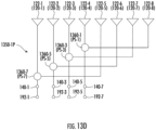
- the first-polarization portion 1350-1P of the coupling circuit 1350 includes the first-polarization coupling elements 1360-1, 1360-3, 1360-5, and 1360-7 .
- the coupling element 1360-1 couples the radio signal port 192-7 to the sub-columns 122-4 and 122-8 .
- the coupling element 1360-3 couples the radio signal port 192-5 to the sub-columns 122-3 and 122-7.
- the coupling element 1360-5 couples the radio signal port 192-3 to the sub-columns 122-2 and 122-6.
- the coupling element 1360-7 couples the radio signal port 192-1 to the sub-columns 122-1 and 122-5.
- Using a single phase shifter PS per polarization can result in all of the columns 120 having equal power.
- a 1:2 wiper-type phase shifter PS may provide a -3 dB power distribution to both its left and right branches.
- the use of a single phase shifter PS per polarization can be more cost-effective than using multiple phase shifters PS per polarization.
- the use of a single phase shifter PS per polarization can somewhat limit azimuth beamsteering because only one radio is connected to the columns 120, full digital beamforming can still be provided in the elevation plane as long as the antenna system includes two or more rows 1330.
Landscapes
- Engineering & Computer Science (AREA)
- Computer Networks & Wireless Communication (AREA)
- Signal Processing (AREA)
- Variable-Direction Aerials And Aerial Arrays (AREA)
- Aerials With Secondary Devices (AREA)
Abstract
Description
- The present application is a continuation-in-part of
U.S. Patent Application Serial No. 17/149,187, filed on January 14, 2021 PCT/CN2020/111926, filed August 27, 2020 - The present invention generally relates to radio communications and, more particularly, to beamforming base station antennas for cellular communications systems.
- Cellular communications systems are well known in the art. In a cellular communications system, a geographic area is divided into a series of regions or "cells" that are served by respective base stations. Each base station may include one or more base station antennas that are configured to provide two-way radio frequency ("RF") communications with subscribers that are within the cell served by the base station. In many cases, each base station is divided into "sectors." In one common configuration, a hexagonally-shaped cell is divided into three 120° sectors in the azimuth plane, and each sector is served by one or more base station antennas that have an azimuth Half Power Beamwidth ("HPBW") of approximately 65°. Typically, the base station antennas are mounted on a tower or other raised structure, with the radiation patterns that are generated by the base station antennas directed outwardly. Base station antennas are often implemented as linear or planar phased arrays of radiating elements.
- In order to increase capacity, base station antennas that include beamforming arrays and/or that are configured to operate with multi-input-multi-output ("MIMO") radios have been introduced in recent years. A beamforming array refers to an antenna array that includes multiple columns of radiating elements. Beamforming arrays can generate antenna beams having reduced (narrower) beamwidths in, for example, the horizontal or "azimuth" plane, which increases the directivity or "gain" of the antenna, thereby increasing the supportable throughput. MIMO refers to a communication technique in which a data stream is broken into pieces that are simultaneously transmitted using certain coding techniques over multiple relatively uncorrelated transmission paths between a transmitting station and a receiving station. Multi-column antenna arrays may be used for MIMO transmissions, where each column in the array may be connected to a port of a MIMO radio and used to transmit/receive one of the multiple data streams. In practice, since orthogonal polarizations tend to be highly uncorrelated, the radiating elements in a MIMO array are typically implemented as dual-polarized radiating elements, allowing each column in the MIMO array to be connected to two ports on the radio (where the first port is connected to the first polarization radiators of the radiating elements in the column, and the second port connected to the second polarization radiators of the radiating elements in the column). This technique can effectively halve the number of columns of radiating elements required, since each physical column of the array contains two independent columns of radiators.
- MIMO and beamforming techniques can also be combined. For example, so-called 8-Transmit/8-Receive ("8T8R") radios (which include eight radio ports) are now routinely connected to antenna arrays that include four columns of dual-polarized radiating elements that are configured to form a single antenna beam per polarization within a sector. The two polarizations may be used to implement 2xMIMO communications for each antenna beam. These beamforming antennas are typically used for time division duplex ("TDD") communications and may generate a single antenna beam during each individual time slot of the TDD communication scheme. Likewise, 16-Transmit/16-Receive ("16T16R") radios (which include sixteen radio ports) are known in the art that are connected to antenna arrays that include eight columns of dual-polarized radiating elements that are configured to form a single antenna beam at a time within a sector. The 16T16R solutions provide higher gain and less interference (and hence support higher data throughput) as compared to the 8T8R solution, but also require a larger array on the antenna and a much more expensive 16T16R radio, which can significantly increase cost.
- Pursuant to embodiments of the present invention, an antenna system may include a beamforming radio having a plurality of first polarization signal sources and a plurality of first polarization radio signal ports, where each first polarization signal source is coupled to all of the first polarization radio signal ports. The antenna system may include an antenna array having a plurality of columns of radiating elements. Moreover, the antenna system may include a coupling circuit that includes a coupler and/or splitter that connects one of the first polarization radio signal ports to at least two of the columns of radiating elements. For example, the splitter may be an RF power divider that connects the one of the first polarization radio signal ports to the at least two of the columns of radiating elements.
- In some embodiments, a total number of the first polarization signal sources may be equal to a total number of the first polarization radio signal ports. Moreover, the coupling circuit may include another coupler and/or splitter that connects the one of the first polarization radio signal ports to at least two rows of the radiating elements.
- According to some embodiments, the beamforming radio may include a total of X first polarization radio signal ports and the antenna array may include a total of Y columns of radiating elements, where X and Y are positive integers and Y is greater than X. For example, Y may be equal to 2*X. Moreover, a total number of couplers and/or splitters included in the coupling circuit that connect the first polarization radio signal ports to the columns of radiating elements in the antenna array may be equal to Y - X, and the coupler and/or splitter may connect the one of the first polarization radio signal ports to fewer than all of the columns of radiating elements.
- In some embodiments, each first polarization signal source may be coupled to all of the columns of radiating elements. Moreover, the splitters may be RF power dividers that couple the Z first polarization antenna signal ports to the Y columns of radiating elements.
- According to some embodiments, the coupling circuit may include a plurality of couplers and/or splitters that connect the first polarization radio signal ports to the columns of radiating elements in the antenna array. Moreover, the antenna system may include a plurality of first polarization antenna signal ports and a Butler Matrix beamforming network that is connected between the first polarization antenna signal ports and the coupling circuit.
- Each coupler and/or splitter in the coupling circuit may, in some embodiments, only be coupled to two of the columns of radiating elements. Moreover, each coupler in the coupling circuit may be a four-port coupler having an input port that is coupled to a respective one of the first polarization radio signal ports, first and second output ports that are coupled to respective ones of the columns of radiating elements, and an isolation port that is coupled to a resistive termination.
- In some embodiments, a hook balun of a radiating element in a first of the columns is flipped as compared to a hook balun of a radiating element in a second of the columns.
- An antenna system, according to embodiments of the present invention, may include a beamforming radio having W first polarization signal sources and X first polarization radio signal ports, where W and X are positive integers, and where each first polarization signal source is coupled to all X of the first polarization radio signal ports. The antenna system may include an antenna including: an antenna array having Y columns of radiating elements, where Y is a positive integer that is greater than X; and Z first polarization antenna signal ports that are coupled to the antenna array, where Z is a positive integer. Moreover, the antenna system may include a coupling circuit that includes a plurality of couplers and/or splitters, the coupling circuit coupling the Z first polarization antenna signal ports to the Y columns of radiating elements.
- In some embodiments, a total number of couplers and/or splitters included in the coupling circuit that couple the Z first polarization antenna signal ports to the Y columns of radiating elements in the antenna array may be equal to Y - Z.
- According to some embodiments, each first polarization signal source may be coupled to all Y columns of radiating elements.
- In some embodiments, each coupler and/or splitter in the coupling circuit may only be coupled to two of the columns of radiating elements.
- According to some embodiments, each coupler in the coupling circuit may be a four-port coupler having an input port that is coupled to a respective one of the first polarization radio signal ports, first and second output ports that are coupled to respective ones of the columns of radiating elements, and an isolation port that is coupled to a resistive termination.
- In some embodiments, W may be equal to X.
- According to some embodiments, Z may be less than Y.
- In some embodiments, the antenna system may include a Butler Matrix beamforming network that is connected between the Z first polarization antenna signal ports and the coupling circuit.
- A base station antenna system, according to embodiments of the present invention, may include a beamforming array having a plurality of vertical columns of radiating elements that are each configured to transmit at least three antenna beams per polarization. Moreover, the base station antenna system may include a beamforming radio having a plurality of radio signal ports per polarization that are coupled to and fewer than the vertical columns. For example, the vertical columns may include at least five vertical columns, and the radio signal ports may include no more than eight radio signal ports that are coupled to the at least five vertical columns. In another example, the vertical columns may include at least five vertical columns, and the radio signal ports may include no more than six radio signal ports that are coupled to the at least five vertical columns. As a further example, the vertical columns may include at least six vertical columns, and the radio signal ports may include no more than ten radio signal ports that are coupled to the at least six vertical columns.
- In some embodiments, the no more than ten radio signal ports of the beamforming radio may include no more than five radio signal ports per polarization that are coupled to the at least six vertical columns. Moreover, the beamforming radio may include a plurality of RF signal sources per polarization that are each coupled to all of the no more than five radio signal ports.
- According to some embodiments, the base station antenna system may include analog RF circuitry that is coupled between the beamforming radio and two of the vertical columns.
- In some embodiments, the analog RF circuitry may include an RF coupler and/or splitter. Also, the two vertical columns may be non-adjacent vertical columns, and RF outputs of the RF coupler and/or splitter may be coupled only to the non-adjacent vertical columns. Moreover, a first output of the RF coupler and/or splitter may be fed to a first of the vertical columns with a first phase, and a second output of the RF coupler and/or splitter may be fed to a second of the vertical columns with a second phase that is offset by 180 degrees from the first phase.
- According to some embodiments, the beamforming array may be part of a base station antenna that includes a plurality of antenna signal ports. The base station antenna system may further include analog RF circuitry that is coupled between the beamforming radio and a pair of the vertical columns. The analog RF circuitry may be configured to couple an RF signal received at a first of the antenna signal ports to at least two of the vertical columns. For example, the analog RF circuitry may be inside the base station antenna. As another example, the analog RF circuitry may be external to the base station antenna.
- In some embodiments, the analog RF circuitry may include an RF coupler and/or splitter that splits an RF signal input to the RF coupler and/or splitter from the first of the antenna signal ports into first and second sub-components. A first output of the RF coupler and/or splitter may be fed to a first of the vertical columns with a first phase, and a second output of the RF coupler and/or splitter may be fed to a second of the vertical columns with a second phase that is offset by 180 degrees from the first phase.
- According to some embodiments, the beamforming radio may include at least four RF signal sources per polarization. Each of the at least four RF signal sources may be configured to generate a respective RF component of each of the at least three antenna beams. Moreover, the beamforming radio may be configured to control each of the at least four RF signal sources to individually turn on or off each of the at least three antenna beams.
- An antenna system, according to some embodiments of the present invention, may include a beamforming radio having a plurality of first polarization signal sources and a plurality of first polarization radio signal ports, where each first polarization signal source is coupled to all of the first polarization radio signal ports. The antenna system may include an antenna array having a plurality of columns and a plurality of rows of radiating elements. Moreover, the antenna system may include a coupling circuit that includes a coupler and/or splitter that connects one of the first polarization radio signal ports to at least two of the rows of radiating elements. For example, the splitter may be an RF power divider that connects the one of the first polarization radio signal ports to the at least two of the rows of radiating elements.
- A MIMO base station antenna system, herein further described as and preferably being a massive MIMO base station antenna system, according to some embodiments of the present invention, may include at least thirty-six groups, each of which includes a plurality of radiating elements. The massive MIMO base station antenna system may include a beamforming radio having fewer than sixty-four radio signal ports that are coupled to the antenna array. Moreover, the massive MIMO base station antenna system may include a coupling circuit that that couples a first of the radio signal ports to at least two of the groups.
- In some embodiments, the beamforming radio may be a 32T32R beamforming radio.
- According to some embodiments, each group may include exactly two radiating elements, and the antenna array may have at least six columns and at least six rows of the groups.
- In some embodiments, each group may include exactly three radiating elements, and the antenna array may have eight columns and four rows of the groups.
- According to some embodiments, a sub-array of the antenna array may include sixteen of the groups.
- In some embodiments, a first row of the groups may include a first group of the sub-array and a second group that is outside of the sub-array. Moreover, the coupling circuit may couple the first group to the second group.
- According to some embodiments, a first column of the groups may include a first group of the sub-array and a second group that is outside of the sub-array. Moreover, the coupling circuit may couple the first group to the second group.
- In some embodiments, a first group of the sub-array may be in a first row and a first column of the groups. A second group that is outside of the sub-array may be in a second row and a second column of the groups. Moreover, the coupling circuit may couple the first group to the second group.
- According to some embodiments, the coupling circuit may be an RF power divider.
- In some embodiments, the coupling circuit may couple the first of the radio signal ports of the beamforming radio to multiple rows and multiple columns of the groups.
- A base station antenna system, according to some embodiments, may include a beamforming radio having a plurality of radio signal ports. The base station antenna system may include an antenna array having a vertical stack of sub-arrays that each include a plurality of sub-columns of dual-polarized radiating elements. A first of the radio signal ports may be coupled to two sub-columns of a first of the sub-arrays. Moreover, a second of the radio signal ports may be coupled to two sub-columns of a second of the sub-arrays.
- In some embodiments, each of the two sub-columns of the first of the sub-arrays may include three of the dual-polarized radiating elements. Moreover, each of the radio signal ports may be coupled to six of the dual-polarized radiating elements.
- According to some embodiments, the first and the second of the sub-arrays may each be coupled to four of the radio signal ports per polarization.
- In some embodiments, a third of the radio signal ports may be coupled to two sub-columns of a third of the sub-arrays. Moreover, a fourth of the radio signal ports may be coupled to two sub-columns of a fourth of the sub-arrays.
- According to some embodiments, each of the two sub-columns of the first of the sub-arrays may include six of the dual-polarized radiating elements.
- In some embodiments, the base station antenna system may include a plurality of first phase shifters per polarization that are coupled to the first of the sub-arrays. The base station antenna system may include a plurality of second phase shifters per polarization that are coupled to the second of the sub-arrays. The first of the radio signal ports may be coupled to the two sub-columns of the first of the sub-arrays via a first of the first phase shifters, and the second of the radio signal ports may be coupled to the two sub-columns of the second of the sub-arrays via a first of the second phase shifters. Moreover, the first of the sub-arrays may be coupled to four of the first phase shifters per polarization, and the second of the sub-arrays may be coupled to four of the second phase shifters per polarization.
- According to some embodiments, the base station antenna system may include a single first phase shifter per polarization that is coupled to every sub-column of the first of the sub-arrays. Moreover, the base station antenna system may include a single second phase shifter per polarization that is coupled to every sub-column of the second of the sub-arrays.
- A massive MIMO base station antenna system, according to some embodiments, may include an antenna array having a plurality of radiating elements. The massive MIMO base station antenna system may include a beamforming radio having fewer than sixty-four radio signal ports that are coupled to the antenna array. Moreover, the massive MIMO base station antenna system may include a coupling circuit that couples a first of the radio signal ports to at least two sub-columns of the radiating elements.
- In some embodiments, the beamforming radio may be a 32T32R beamforming radio.
- According to some embodiments, each sub-column may include exactly two radiating elements or exactly one radiating element. In other embodiments, each sub-column may include exactly three radiating elements, and the antenna array may have eight columns and four rows of the sub-columns.
- In some embodiments, a sub-array of the antenna array may include eight of the sub-columns. Moreover, the coupling circuit may include a phase shifter.
- A base station antenna system, according to some embodiments, may include a beamforming radio having a plurality of radio signal ports. The base station antenna system may include an antenna array having a plurality of rows and a plurality of columns of radiating elements. Each of the radio signal ports may be coupled to at least two of the columns and no more than half of the rows.
- In some embodiments, each of the rows may be coupled to four of the radio signal ports per polarization, and each of the columns may include four sub-columns that are coupled to four of the radio signal ports, respectively, per polarization.
- According to some embodiments, each of the radio signal ports may be coupled to one-quarter or one-third of the rows.
-
-
FIG. 1A is a schematic front view of a conventional antenna system that includes an 8T8R radio and an antenna array that includes four columns of dual-polarized radiating elements. -
FIG. 1B is a table illustrating the relative amplitudes and phases applied to the signals fed to the four columns of the antenna array ofFIG. 1A in order generate eight antenna beams (four at each polarization). -
FIG. 2A is a schematic front view of an antenna system according to embodiments of the present invention that includes an 8T8R radio, a coupling circuit, and an antenna array that includes six columns of dual-polarized radiating elements. -
FIG. 2B is a schematic diagram illustrating a coupling circuit according to embodiments of the present invention that can be used to couple the 8T8R radio ofFIG. 2A to the six-column antenna array ofFIG. 2A . -
FIG. 2C is a table illustrating the relative amplitudes and phases applied to the signals fed to the six columns of the antenna array ofFIG. 2A in order generate eight antenna beams (four at each polarization). -
FIG. 3A is a schematic front view of an antenna system according to embodiments of the present invention that includes an 8T8R radio, a coupling circuit, and an antenna array that includes eight columns of dual-polarized radiating elements. -
FIG. 3B is a schematic diagram illustrating a coupling circuit according to embodiments of the present invention that can be used to couple the 8T8R radio ofFIG. 3A to the eight-column antenna array ofFIG. 3A . -
FIG. 3C is a table illustrating the relative amplitudes and phases applied to the signals fed to the four columns of the antenna array ofFIG. 3A via the coupling circuit ofFIG. 3B in order generate eight antenna beams (four at each polarization). -
FIG. 3D is a schematic diagram illustrating another coupling circuit according to embodiments of the present invention that can be used to couple the 8T8R radio ofFIG. 3A to the eight-column antenna array ofFIG. 3A . -
FIG. 3E is a table illustrating the relative amplitudes and phases applied to the signals fed to the four columns of the antenna array ofFIG. 3A via the coupling circuit ofFIG. 3D in order generate eight antenna beams (four at each polarization). -
FIG. 4A is a schematic front view of an antenna system according to embodiments of the present invention that includes a 10T10R radio, a coupling circuit, and an antenna array that includes eight columns of dual-polarized radiating elements. -
FIG. 4B is a schematic diagram illustrating a coupling circuit according to embodiments of the present invention that can be used to couple the 10T10R radio ofFIG. 4A to the eight-column antenna array ofFIG. 4A . -
FIG. 4C is a table illustrating the relative amplitudes and phases applied to the signals fed to the eight columns of the antenna array ofFIG. 4A via the coupling circuit ofFIG. 4B in order generate the ten antenna beams (five at each polarization). -
FIG. 5A is a schematic front view of an antenna system according to embodiments of the present invention that includes a 4T4R radio, a coupling circuit, and an antenna array that includes four columns of dual-polarized radiating elements. -
FIG. 5B is a schematic diagram illustrating a coupling circuit according to embodiments of the present invention that can be used to couple the 4T4R radio ofFIG. 5A to the four-column antenna array ofFIG. 5A . -
FIG. 5C is a table illustrating the relative amplitudes and phases applied to the signals fed to the four columns of the antenna array ofFIG. 5A via the coupling circuit that is shown inFIG. 5B in order generate four antenna beams (two at each polarization). -
FIG. 6A is a schematic front view of an antenna system according to embodiments of the present invention that includes a 8T8R radio, a coupling circuit, and an antenna array that includes five columns of dual-polarized radiating elements. -
FIG. 6B is a schematic diagram illustrating a coupling circuit according to embodiments of the present invention that can be used to couple the 8T8R radio ofFIG. 6A (with two ports unused) to the five-column antenna array ofFIG. 6A . -
FIG. 6C is a table illustrating the relative amplitudes and phases applied to the signals fed to the five columns of the antenna array ofFIG. 6A via the coupling circuit that is shown inFIG. 6B in order generate the four antenna beams (two at each polarization). -
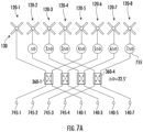
FIG. 7A is a schematic block diagram of an example implementation of the antenna array and coupling circuit of the antenna system ofFIGS. 3A-3B (illustrating one polarization only). -
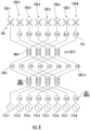
FIG. 7B is a schematic block diagram illustrating how the first polarization signal sources of an 8T8R radio may be coupled to the antenna array and coupling circuit ofFIG. 7A . -
FIG. 8 is a schematic diagram of an antenna system according to embodiments of the present invention. -
FIG. 9 is a schematic diagram illustrating how the antenna systems according to embodiments of the present invention may be viewed as including a plurality of multi-column sub-arrays. -
FIG. 10 is a schematic diagram illustrating a Butler Matrix beamforming network that is connected to the coupling circuit ofFIG. 3D . -
FIGS. 11A and11B are schematic front views of massive MIMO antenna systems according to embodiments of the present invention. -
FIG. 12A is a schematic diagram illustrating a coupling circuit according to embodiments of the present invention that can be used to couple a port of the 32T32R radio ofFIG. 11A to multiple rows and multiple columns of the antenna array ofFIG. 11A . -
FIG. 12B is a schematic diagram illustrating a coupling circuit according to embodiments of the present invention that can be used to couple a port of the 32T32R radio ofFIG. 11B to multiple rows and multiple columns of the antenna array ofFIG. 11B . -
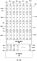
FIG. 13A is a schematic front view of a massive MIMO antenna system having four rows according to embodiments of the present invention. -
FIG. 13B is a schematic diagram illustrating a first-polarization portion and a second-polarization portion of the coupling circuit ofFIG. 13A coupled to the rows ofFIG. 13A . -
FIG. 13C is an enlarged schematic diagram illustrating a first of the rows ofFIG. 13A . -
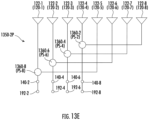
FIGS. 13D and13E are schematic diagrams illustrating examples in which the coupling circuit ofFIG. 13A includes a plurality of elements per polarization that are coupled between ports of the 32T32R radio ofFIG. 13A and multiple columns of the antenna array ofFIG. 13A . -
FIG. 13F is a schematic diagram illustrating a further example in which the coupling circuit ofFIG. 13A includes a single phase shifter per polarization that is coupled to a first of the rows ofFIG. 13A . -
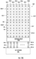
FIG. 13G is a schematic front view of a massive MIMO antenna system that is modified relative to the system ofFIG. 13A to provide two rows. -
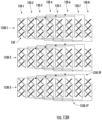
FIGS. 13H and13I are schematic diagrams that are modified relative to the diagram ofFIG. 13B to provide three rows and two rows, respectively. - Pursuant to embodiments of the present invention, antenna systems (e.g., base station antenna systems) are provided that include antenna arrays that have multiple columns of radiating elements, where at least some of the columns are coupled to the same RF ports of a radio (herein "radio signal ports"). The radiating elements may be dual-polarized radiating elements so that the multi-column antenna array may generate multiple antenna beams at each polarization. In example embodiments, an eight-column (or six-column) antenna array may be fed by a radio that has fewer than eight (or fewer than six) radio signal ports per polarization. In particular, a coupling circuit that may include analog RF components, such as RF couplers and/or splitters, may couple at least some of the radio signal ports to respective pairs of columns of the antenna array. As a result, the radio may include fewer radio signal ports (per polarization) than there are columns of the antenna array. This allows the antenna systems according to embodiments of the present invention to provide improved antenna patterns and higher gains while using relatively inexpensive radios.
- As discussed above, conventionally, 8T8R TDD beamforming radios are used in conjunction with antenna arrays having four columns of dual-polarized radiating elements. This implementation provides a relatively low cost beamforming solution, but may suffer from low gain (and hence low capacity) and relatively coarse antenna patterns that are not ideal. If higher performance is required, 16T16R TDD beamforming radios may be used in conjunction with antenna arrays having eight columns of dual-polarized radiating elements. This implementation provides increased gain, improved antenna beams and supports higher capacity, but may be significantly more expensive. Pursuant to embodiments of the present invention, antenna systems are provided that may, for example, include an 8T8R TDD beamforming radio in conjunction with antenna arrays having more than four columns of dual-polarized radiating elements(e.g., six columns or eight columns). This implementation provides increased gain and improved antenna beams as compared to the low cost solution discussed above, although not quite as good of performance as the high capacity solution. The antenna systems according to embodiments of the present invention thus may provide an intermediate solution that may be acceptable for many applications that previously required the high cost solution.
- Embodiments of the present invention will now be discussed in greater detail with reference to the attached figures.
-
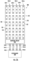
FIG. 1A is a schematic front view of aconventional antenna system 100 that includes an8T8R radio 190 and anantenna 110 having anantenna array 112 that includes four columns 120-1 through 120-4 of dual-polarized radiatingelements 130. Each radiatingelement 130 may comprise, for example, a crossed-dipole radiating element that includes afirst dipole radiator 132 and asecond dipole radiator 134 that crosses/intersects thefirst dipole radiator 132. Thedipole radiators elements 130. Note that herein when multiple like elements are provided, they may be numbered using two-part reference numerals. These elements may be referred to individually by their full reference numeral (e.g., column 120-3), and may be referred to collectively by the first part of their reference numeral (e.g., the columns 120). - The array of columns 120 may be inside a radome of the antenna 110 (not shown). The
antenna 110 may include RF ports 140-1 through 140-8, which may also be referred to herein as "connectors" or "antenna signal ports," that are coupled (e.g., electrically connected) to the columns 120. In particular, antenna signal ports 140-1, 140-3, 140-5 and 140-7 are coupled to thefirst radiators 132 of the radiatingelements 130 of columns 120-1, 120-2, 120-3 and 120-4, respectively, and antenna signal ports 140-2, 140-4, 140-6 and 140-8 are coupled to thesecond radiators 134 of the radiatingelements 130 of columns 120-1, 120-2, 120-3 and 120-4, respectively. As is further shown inFIG. 1A , theantenna signal ports 140 are also coupled to respective radio signal ports 192 of theradio 190 by respective RF transmission lines 194-1 through 194-8, such as coaxial cables. For example, theradio 190 may be a TDD beamforming radio for a cellular base station, and theantenna 110 and theradio 190 may be located at (e.g., may be components of) a cellular base station. - Because the
radio 190 is shown as an 8T8R radio, it includes eight RF ports 192-1 through 192-8 that pass RF communication signals between the internal components of theradio 190 and theantenna array 112. These ports 192 may also be referred to herein as "radio signal ports." For example, four of the radio signal 192 may be first polarization ports and another four of the radio signal 192 may be second polarization ports, where the first and second polarizations are different polarizations. Theradio 190 may also include one or more calibration ports (not shown) that are not radio signal ports, but instead are ports that may be used in calibrating the internal circuitry of theradio 190 to account for amplitude and phase differences between the RF signal paths external to theradio 190. - The
8T8R radio 190 includes four RF first polarization signal sources and four second polarization signal sources. Each first polarization RF signal source inradio 190 is coupled to the four first polarization radio signal ports (here radio signal ports 192-1, 192-3, 192-5, 192-7), and each second polarization RF signal source inradio 190 is coupled to the four second polarization radio signal ports (here radio signal ports 192-2, 192-4, 192-6, 192-8). -
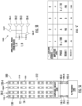
FIG. 1B is a table illustrating the relative amplitudes and phases applied to the RF signals fed to the four columns of the antenna array ofFIG. 1A in order generate eight antenna beams (four at each polarization). The table ofFIG. 1B only illustrates the relative amplitudes and phases of the RF signals fed to thefirst polarization radiators 132 of the columns 120. It will be appreciated that the same relative amplitudes and phases of the RF signals fed to thefirst polarization radiators 132 of the columns 120. - In
FIG. 1B , the rows labeled "Beam X" (X = 1, 2, 3, 4) show the relative phases of the four RF signals that are provided to the first radiators 123 of the radiatingelements 130 in the four columns 120. Thus, for example, the first signal source (Beam 1) outputs a signal having a relative amplitude of 0 dB and a relative phase of -405 to theradiators 132 of the first column 120-1, outputs a signal having a relative amplitude of 0 dB and a relative phase of -270 to theradiators 132 of the second column 120-1, outputs a signal having a relative amplitude of 0 dB and a relative phase of -135 to theradiators 132 of the third column 120-3, and outputs a signal having a relative amplitude of 0 dB and a relative phase of 0 to theradiators 132 of the fourth column 120-4. The four RF signals output by the first signal source inradio 190 to the four columns 120-1 through 120-4 as described above generate a first antenna beam that points in a first direction in the azimuth plane. The second, third and fourth signal sources inradio 190 generate second, third and fourth antenna beams that point in three additional directions in the azimuth plane. -
FIG. 1B also shows the phases that may be applied by theradio 190 in order to generate a so-called "broadcast" beam. As is known in the art, a broadcast beam refers to a beam that is formed by a beamforming antenna that is a wide beamwidth beam that is designed to cover the entire coverage area that is served by the antenna system. The broadcast beam is a single beam that is used to communicate with all users throughout the coverage area. -
FIG. 2A is a schematic front view of anantenna system 200 according to embodiments of the present invention that includes an 8T8R radio 290 (e.g., a TDD beamforming radio), acoupling circuit 250, and anantenna 210 havingantenna array 212 that includes six columns 120-1 through 120-6 of dual-polarized radiatingelements 130. It will be appreciated that theantenna system 200 may include additional columns of radiating elements (not shown). - The
antenna 210 may includeantenna signal ports 140 that are coupled to the columns 120. Theantenna signal ports 140 are also coupled to respective radio signal ports 192 of theradio 290 by RF transmission lines 194. Theradio 290 may be a TDD beamforming radio, and theantenna 210 and theradio 290 may be located at (e.g., may be components of) a cellular base station. - The columns 120 may be referred to herein as "vertical" columns, as they may extend in a vertical direction from a lower portion of the
antenna 210 to an upper portion of theantenna 210. The vertical direction may be, or may be parallel with, a longitudinal axis of theantenna 210, which may be perpendicular to the horizon. As used herein, the term "vertical" does not necessarily require that something is exactly vertical (e.g., theantenna 210 may have a small mechanical down-tilt). Additionally, in the depicted embodiment, the radiatingelements 132 are arranged in true rows and columns. It will be appreciated that in many cases every other column 120 may be offset in the vertical direction so that every column 120 is "staggered" in the vertical direction with respect to its one or more adjacent columns 120. This "staggered" approach may increase the distance between radiatingelements 132 in adjacent columns 120 and hence improve the isolation between adjacent columns 120. - The
coupling circuit 250 connects (e.g., electrically connects) theantenna signal ports 140 to the columns 120. Specifically, thecoupling circuit 250 is configured to split an RF signal that is input to a first of theantenna signal ports 140 into two sub-components and to feed the two sub-components of this RF signal to thefirst polarization radiators 132 of the radiatingelements 130 in respective first and second of the columns 120. Thecoupling circuit 250 is further configured to split an RF signal that is input to a second of theantenna signal ports 140 into two sub-components and to feed the two sub-components of this RF signal to thefirst polarization radiators 132 of the radiatingelements 130 in respective third and fourth of the columns 120. Thecoupling circuit 250 is likewise configured to similarly split RF signals that are input to third and fourth of theantenna signal ports 140 into respective pairs of sub-components and to feed those sub-components to thesecond polarization radiators 130 of the radiatingelements 130 in a similar fashion. Thecoupling circuit 250 may comprise various types of analog RF circuitry, such as a plurality of RF couplers and/or a plurality of RF splitters/combiners (e.g., RF power dividers). Though shown inFIG. 2A as being inside theantenna 210, thecoupling circuit 250 may, in some embodiments, be external to theantenna 210. As an example, thecoupling circuit 250 may be a standalone device that is coupled between (a) the radio signal ports 192 and (b) theantenna signal ports 140. - Because the
radio 290 is shown as an 8T8R radio, it includes eight radio signal ports 192-1 through 192-8. Four of the radio signal ports 192 may be first polarization ports and another four of the radio signal ports 192 may be second polarization ports, where the first and second polarizations are different polarizations. As will be discussed below, other radios having different numbers of radio signal ports may be used in other embodiments. For example, in some embodiments, a 4T4R radio having four radio signal ports or a 10T10R radio having ten radio signal ports 192 (e.g., five first polarization radio signal ports and five second polarization radio signal ports) may be used instead of the8T8R radio 290. - The number of columns 120 of dual-polarized radiating
elements 130 included inantenna 210 exceeds the number of first polarization radio signal ports 192 included onradio 290. In order utilize all six columns 120 at both polarizations, at least some of the radio signal ports 192 are shared across multiple (here two) columns 120 using thecoupling circuit 250. Thus, by providing thecoupling circuit 250, the correspondence between the number of columns and the number of first (or second) polarization radio signal ports on the beamforming radio may be broken, and hence theantenna 210 may include five, six, seven, eight, or more columns 120, even though theradio 290 only has four radio signal ports 192 per polarization. - Butler Matrices have been used in the past to couple radio signal ports to a multi-column antenna array, where the number of radio signal ports per polarization did not necessarily equal the number of columns of radiating elements in the antenna array. However, such conventional techniques were used with multiple standard frequency division duplex ("FDD") radios to form multiple static antenna beams for sector-splitting operations. Each radio signal port was connected to a single signal source, and the Butler Matrix was used to split and phase shift the RF signals provided by each signal source so as to feed the RF signals to all of the columns in the antenna array. This typically required a series of layers of hybrid couplers or other analog circuit elements that could significantly increase the insertion loss of the antenna. Pursuant to embodiments of the present invention, beamforming radios may be used that feed combined signal sources in the digital domain so that each radio signal port may output sub-components of the RF signals generated by multiple signal sources. A small number of additional analog components (e.g., hybrid couplers or Wilkinson power dividers) may then be used to further sub-divide the RF signals output at one or more of the radio signal ports so that all of the columns 120 of the
antenna array 212 are fed. In other words, theradio 290 may perform some beamforming RF signal operations in a digital domain, thereby simplifying antenna system hardware and improving insertion loss. For example, as will be discussed below with reference toFIG. 7B , in one example embodiment theradio 290 may include four RF signal sources 715 and may be configured to combine the RF signals generated by all four signal sources 715 before outputting the combined signal from a radio signal port 192. Each of the signal sources 715 may be coupled to all of the radio signal ports 192 and may be configured to generate a respectiveRF signal component 716 of each antenna beam that the columns 120 transmit, and theradio 290 may be configured to control each of the signal sources 715 to individually turn on or off each antenna beam. - Though the
system 200 has only oneradio 290, antenna systems according to other embodiments of the present invention may include multiple radios that are coupled to the same antenna array. For example, additional radios and diplexers could be provided to provide a frequency division duplex ("FDD") twin-beam or tri-beam or quad-beam antenna system that operated in a different sub-band of the operating frequency range of the radiatingelements 130 so that theantenna array 212 may be used as a TDD beamforming array in the first sub-band and as an FDD sector splitting array in the second sub-band. -
FIG. 2B is a schematic diagram illustrating acoupling circuit 250 according to embodiments of the present invention that can be used to couple the8T8R radio 290 ofFIG. 2A to the six-column antenna array 212 ofFIG. 2A . As shown inFIG. 2B , thecoupling circuit 250 may include first and second couplers and/or splitters 260-1 and 260-2. The first coupler and/or splitter 260-1 connects (e.g., electrically connects) a first antenna signal port 140-1 to both a second column 120-2 and a sixth column 120-6. Similarly, the second coupler and/or splitter 260-2 connects a seventh antenna signal port 140-7 to both a first column 120-1 and a fifth column 120-5. - The ports 140-1 and 140-7, as well as ports 140-3 and 140-5, may be first polarization ports. For simplicity of illustration, second polarization antenna signal ports 140-2, 140-4, 140-6, and 140-8 are omitted from view in
FIG. 2B . Anidentical coupling circuit 250 may be used to couple the second polarization antenna signal ports 140-2, 140-4, 140-6, and 140-8 to the six columns 120-1 through 120-6 ofantenna array 212. Moreover, in some embodiments, thecoupling circuit 250 may be external to theantenna 210, and the couplers and/orsplitters 260 may thus couple radio signal ports 192 to respective pairs ofantenna signal ports 140. - The couplers and/or splitters 260-1 and 260-2 are coupled to respective non-adjacent pairs of columns 120. As used herein with respect to columns 120, the term "non-adjacent" refers to two columns 120 that have least one other column 120 therebetween. For example,
FIG. 2B shows that each commonly-coupled pair has three columns 120 therebetween. Accordingly, the same distance can separate each commonly-coupled pair. - In some embodiments, the couplers and/or splitters 260-1 and 260-2 may be respective analog RF couplers. Herein, the term "coupling circuit" is used to cover a wide variety of power coupling and/or splitting devices, including four-port devices such as hybrid couplers, branch line couplers, rat race couplers, and the like, and three-port devices such as Wilkinson power couplers/dividers and the like.
- Moreover, a coupling circuit according to other embodiments may include more than two couplers and/or splitters that are coupled to respective pairs of columns 120. In some embodiments, the total number of couplers and/or splitters (in a coupling circuit) that couple X first polarization antenna signal ports 192 to Y columns 120 (via Z first polarization antenna signal ports 140 (
FIG. 2A ) of an antenna) may be equal to Y - X and/or may be equal to Y - Z, where X, Y and Z are positive integers and Y is larger than both X and Z. In some embodiments, the total number of couplers and/or splitters may be equal to X. As a result, Y may equal 2*X in some embodiments and RF outputs of each coupler and/or splitter may thus be coupled to only (i.e., exactly) two columns 120. In other embodiments, a 4x4 Butler matrix may be used that includes 4 couplers that connect Z = 4ports 140 with Y = 4, 6, or 8 columns 120. - In some embodiments, the
radio 290 may include W first polarization signal sources that are each coupled to all of the X radio signal ports 192. Each first polarization signal source may also be coupled by thecoupling circuit 250 to all of the Y columns 120 of theantenna array 212. - Each coupler and/or
splitter 260 may, in some embodiments, be a four-port coupler having (i) an RF input port that is coupled to a respective one of the X radio signal ports 192, (ii) a first RF output port that is coupled to one of the Y columns 120, (iii) a second RF output port that is coupled to another of the Y columns 120, and (iv) an isolation port that is coupled to a resistive termination (e.g., a 50-Ohm resistor). - In some embodiments, the orientation of the hook baluns on the
dipole radiators elements 130 included in columns 120-1 and 120-6 may be reversed as compared to the orientation of the hook baluns on thedipole radiators elements 130 included in columns 120-2 through 120-5. By reversing or "flipping" the hook baluns ondipole radiators FIG. 2A ), the phases of the RF signals fed to the radiatingelements 130 of columns 120-1 and 120-6 may be shifted by 180 degrees relative to the phases of the RF signals fed to the radiatingelements 130 of columns 120-2 and 120-5. Moreover, in some embodiments, the columns 120 may be spaced apart by about 0.5 wavelengths at the operating frequency (e.g., by at least 62 millimeters ("mm")). - The
antenna system 200 may provide improved performance as compared to theconventional antenna system 100 ofFIG. 1A . In particular, since theantenna array 212 includes six columns 120 of radiating elements (versus the four columns 120 included in antenna system 100) the gain ofantenna array 212 may be approximately 0.4 dB greater than the gain ofantenna array 112. Additionally, the antenna beams (e.g., at least three beams per polarization) generated byantenna array 212 may exhibit improved roll-off as compared to the antenna beams generated byantenna array 112. -
FIG. 2C is a table illustrating the relative amplitudes and phases applied to the signals fed to the six columns of the beamforming antenna array ofFIG. 2A in order generate eight antenna beams (four at each polarization). The table ofFIG. 2C may be interpreted in the same fashion as described above with reference to the similar table ofFIG. 1B . The amplitudes shown forcolumns - As shown in
FIG. 2C , two columns 120 that are commonly coupled to a coupler and/orsplitter 260 may transmit 180 degree phase-shifted versions of the same signal. For example, the fifth column 120-5 may transmit a signal having a phase "D" while the first column 120-1 may transmit an RF signal having a phase of D +/- 180 degrees. Similarly the second column 120-2 may transmit a signal having a phase "A" while the sixth column 120-6 may transmit an RF signal having a phase of A +/- 180 degrees. - These phase offsets, however, may not necessarily be exactly 180 degrees. In particular, the phase offsets can be adjusted via a phase shifter so that they are not exactly 180 degrees. This can allow different beamforming possibilities, and can avoid having sub-array patterns for coupled columns 120 that have local minima at given angles. More precisely, though the minima may still exist, control can be provided over where they occur.
- Moreover, each antenna beam may be transmitted with a different respective phase for all of the columns 120. As an example, the RF signals fed to the six columns 120 to form the first antenna beam (
Beam 1 inFIG. 2C ) may have phases of -540 degrees, -405 degrees, -270 degrees, -135 degrees, 0, and +135 degrees at the columns 120-1 through 120-6, respectively. The phases do not, however, have to be in an arithmetic sequence and thus can be widely adjusted. Also, different antenna beams may be transmitted with different sets of phases for the columns 120, as is further shown in the table ofFIG. 2C . - It should also be noted that the amplitudes of the signals are fed to the different columns 120. In particular, the RF signals fed to columns 120-3 and 120-4 may have a relative amplitude of 0 dB since these signals are not passed through a coupler and/or splitter. The couplers and/or
splitters 260 may be implemented as four-port hybrid couplers, which may be assumed to have an insertion loss of, for example, 1 dB. The smaller signal output by each coupler and/orsplitter 260 is fed to the outer column 120, and hence the signals fed to columns 120-1 and 120-6 may have relative amplitudes of -4.76 dB (i.e., an insertion loss of 1 dB and the coupler and/orsplitter 260 reduces the magnitude of the signal by an additional 3.76 dB), and the signals fed to columns 120-2 and 120-5 may have relative amplitudes of -1.76 dB (i.e., an insertion loss of 1 dB and the coupler and/orsplitter 260 reduces the magnitude of the signal by an additional 0.76 dB). - Each antenna beam (i.e.,
Beam 1 throughBeam 4 inFIG. 2C ) may provide coverage to a different portion of a 120 degree sector in some embodiments. Moreover, these antenna beams may be referred to herein as "switched" or "switchable" beams because they can be selectively transmitted to one or more particular sectors. For example, thebeamforming radio 290 may generate only one antenna beam (e.g.,Beam 1 orBeam 3, as two examples) during a first time slot of the TDD communication frame, and may generate more than one antenna beam during other time slots (e.g., two antenna beams, three antenna beams, or all four antenna beams). - In some embodiments, the antenna array 212 (or any of the other antenna arrays according to embodiments of the present invention that are described herein) may be designed to operate in multiple sub-bands of an operating frequency band of the radiating
elements 130. For example, the radiatingelements 130 may be designed to operate in the 2.2-2.7 GHz operating frequency band (or the 1.7-2.7 GHz operating frequency band). In such embodiments, theantenna array 212 may be designed to operate in either or both the 2.3 GHz sub-band or the 2.6 GHz sub-band, for example. In such an embodiment, the antenna array could be coupled to a 2.3 GHz TDD beamforming radio for operation in the 2.3 GHz sub-band, or could be coupled to a 2.6 GHz TDD beamforming radio for operation in the 2.6 GHz sub-band. Alternatively, diplexers could be used (which could be either internal to theantenna 210 or external to the antenna 210) that allow both a 2.3 GHz TDD beamforming radio and a 2.6 GHz TDD beamforming radio to simultaneously transmit and receive RF signals through theantenna array 212. In such embodiments, the spacing between adjacent columns may be selected so that the distance between adjacent columns is close to 0.5 wavelengths in both operating frequency bands. For example, a spacing of 62 mm between adjacent columns corresponds to 0.47 wavelengths at 2.3 GHz and to 0.54 wavelengths at 2.6 GHz, which represents a compromise in order to obtain good (but not ideal) performance in both sub-bands. - As is further shown in
FIG. 2C , theantenna system 200 can also generate a broadcast beam that provides coverage to the full coverage area of theantenna 210. This broadcast beam may be used to, for example, transmit common control signals to all of the users within the coverage area of theantenna 210. It will be appreciated that each of the antenna systems according to embodiments of the present invention may be configured to generate such broadcast beams. -
FIG. 3A is a schematic front view of anantenna system 300 according to embodiments of the present invention that includes an8T8R radio 290, acoupling circuit 350, and anantenna 310 having anantenna array 312 that includes eight columns 120-1 through 120-8 of dual-polarized radiatingelements 130. Theantenna array 312 thus includes two more columns 120 than the antenna array 212 (FIG. 2A ) and four more than the antenna array 112 (FIG. 1A ). Accordingly, thecoupling circuit 350 may include more couplers and/or splitters than the coupling circuit 250 (FIG. 2A ). Moreover, to improve azimuth side lobes (e.g., by about 2-3 decibels ("dB")), one or more outer columns 120-1, 120-2, 120-7, and 120-8 may include fewer radiatingelements 130 than inner columns 120-3 through 120-6. -
FIG. 3B is a schematic diagram illustrating acoupling circuit 350 according to embodiments of the present invention that can be used to couple the8T8R radio 290 ofFIG. 3A to the eight-column antenna array ofFIG. 3A . Thecoupling circuit 350 may include four couplers and/or splitters 360-1 through 360-4. Each of the couplers and/or splitters 360 may electrically connect a respective radio signal port 192 of the radio 290 (via a respectiveantenna signal port 140 of the antenna 310) to a pair of columns 120. - The first coupler and/or splitter 360-1 connects a first antenna signal port 140-1 of the
antenna 310 to both the first column 120-1 and the fifth column 120-5. The second coupler and/or splitter 360-2 connects a third antenna signal port 140-3 of theantenna 310 to both the second column 120-2 and the sixth column 120-6. The third coupler and/or splitter 360-3 connects a fifth antenna signal port 140-5 of theantenna 310 to both the third column 120-3 and the seventh column 120-7. Similarly, the fourth coupler and/or splitter 360-4 connects a seventh antenna signal port 140-7 of theantenna 310 to both the fourth column 120-4 and the eighth column 120-8. The antenna signal ports 140-1, 140-3, 140-5, and 140-7 may be first polarization ports. For simplicity of illustration, second polarization ports 140-2, 140-4, 140-6, and 140-8 are omitted from view inFIG. 3B . An identical circuit including another four couplers and/or splitters 360 may connect the second polarization ports 140-2, 140-4, 140-6, and 140-8 to the eight columns 120 ofantenna array 212. - In some embodiments, the orientation of the hook baluns on the
dipole radiators elements 130 included in columns 120-5 through 120-8 may be reversed as compared to the orientation of the hook baluns on thedipole radiators elements 130 included in columns 120-1 through 120-4, thus offsetting the phases of the signals fed to the four left-side columns 120 as compared to the four right-side columns 120 by 180 degrees. Moreover, the columns 120 may be spaced apart from each other by at least 62 mm in some embodiments. -
FIG. 3C is a table illustrating the relative amplitudes and phases applied to the signals fed to the four columns 120 of theantenna array 312 ofFIG. 3A via thecoupling circuit 350 ofFIG. 3B in order generate eight antenna beams (four at each polarization). The table ofFIG. 3C may be interpreted in the same manner as the table ofFIG. 1B , which is described in detail above. It will be appreciated that the amplitudes and phases shown in the table ofFIG. 3C may be adjusted in order to "tune" the shapes of the generated antenna beams in order to meet customer requirements. The amplitudes shown are merely examples. -
FIG. 3D is a schematic diagram illustrating another coupling circuit 350' according to embodiments of the present invention that can be used to couple the8T8R radio 290 ofFIG. 3A to the eight-column antenna array 312 ofFIG. 3A . The first coupler and/or splitter 360-1 connects the first antenna signal port 140-1 of theantenna 310 to both the third column 120-3 and the seventh column 120-7. The second coupler and/or splitter 360-2 connects the third antenna signal port 140-3 to both the fourth column 120-4 and the eighth column 120-8. The third coupler and/or splitter 360-3 connects the fifth antenna signal port 140-5 to both the first column 120-1 and the fifth column 120-5. Similarly, the fourth coupler and/or splitter 360-4 connects the seventh antenna signal port 140-7 to both the second column 120-2 and the sixth column 120-6. Accordingly, as shown inFIGS. 3B and 3D , the couplers and/or splitters 360 can feed various combinations of non-adjacent columns 120. - In some embodiments, the orientation of the hook baluns on the
dipole radiators elements 130 included in columns 120-1, 120-2, 120-7 and 120-8 may be reversed as compared to the orientation of the hook baluns on thedipole radiators elements 130 included in columns 120-3 through 120-6 in order to implement the phase shifts between the signals fed to various of the columns 120. Moreover, the columns 120 may be spaced apart from each other by at least 62 mm. -
FIG. 3E is a table illustrating the relative amplitudes and phases applied to the signals fed to the four columns 120 of theantenna array 312 ofFIG. 3A via the coupling circuit 350' ofFIG. 3D in order generate eight antenna beams (four at each polarization). The table ofFIG. 3E may be interpreted in the same manner as the table ofFIG. 1B , which is described in detail above. It will be appreciated that the amplitudes and phases shown in the table ofFIG. 3E may be adjusted in order to "tune" the shapes of the generated antenna beams in order to meet customer requirements. - In the table of
FIG. 3E , the amplitudes for the RF signals fed to some of the columns are shown being within various ranges. For example, the amplitude of the RF signal fed to column 120-2 is shown as being in the range of -10.4 dB to -4.76 dB, and the amplitude of the RF signal fed to column 120-3 is shown as being in the range of -0.4 dB to - 1.76 dB. This illustrates how couplers and/or splitters having different power division ratios may be used in order to fine tune the shapes of the antenna beams in order to meet customer requirements. -
FIG. 4A is a schematic front view of anantenna system 400 according to further embodiments of the present invention that includes a10T10R radio 490, acoupling circuit 450, and anantenna 410 having anantenna array 412 that includes eight columns 120 of dual-polarized radiatingelements 130. -
FIG. 4B is a schematic diagram illustrating an embodiment of thecoupling circuit 450 that can be used to couple the10T10R radio 490 ofFIG. 4A to the eight-column antenna array ofFIG. 4A . Thecoupling circuit 450 may include three couplers and/or splitters 460-1 through 460-3. Each of the couplers and/or splitters 460 may electrically connect a respective radio signal port 192 of the radio 490 (via a respectiveantenna signal port 140 of the antenna 410) to a pair of columns 120 ofantenna array 412. - The first coupler and/or splitter 460-1 connects the first antenna signal port 140-1 to both the first column 120-1 and the sixth column 120-6. The second coupler and/or splitter 460-2 connects the third antenna signal port 140-3 to both the second column 120-2 and the seventh column 120-7. Likewise, the third coupler and/or splitter 460-4 connects the fifth antenna signal port 140-5 to both the third column 120-3 and the eighth column 120-8. Accordingly, each commonly-coupled pair of columns 120 may be a non-adjacent pair having four columns 120 therebetween.
- Columns 120-4 and 120-5 may, in some embodiments, be individually (rather than commonly) coupled to respective antenna signal ports 140-7 and 140-9. Antenna signal ports 140-1 and 140-5, as well as antenna signal ports 140-3, 140-7, and 140-9, may be first polarization ports. For simplicity of illustration, second polarization antenna signal ports 140-2, 140-4, 140-6, 140-8, and 140-10 are omitted from view in
FIG. 4B . An identical circuit including three additional couplers and/or splitters 460 may be used to couple the second polarization antenna signal ports 140-2, 140-4, 140-6, 140-8, and 140-10 to thesecond polarization radiators 134 of the radiatingelements 130 inantenna array 412. - The
coupling circuit 450 may be configured to provide a 180-degree phase offset between commonly-coupled columns 120. Moreover, the columns 120 may be spaced apart from each other by about 62 mm. -
FIG. 4C is a table illustrating the relative amplitudes and phases applied to the signals fed to the eight columns of the antenna array ofFIG. 4A via the coupling circuit ofFIG. 4B in order generate the ten antenna beams (five at each polarization). As shown inFIG. 4C , in an example embodiment, columns 120-1 through 120-3 may be fed RF signals having the same amplitude and phase as the RF signals fed to columns 120-6 through 120-8, respectively. Columns 120-4 and 120-5, on the other hand, may be fed RF signals different amplitudes and phases. -
FIG. 5A is a schematic front view of anantenna system 500 according to embodiments of the present invention that includes a4T4R radio 590, acoupling circuit 550, and anantenna 510 having anantenna array 512 that includes four columns 120 of dual-polarized radiatingelements 130. -
FIG. 5B is a schematic diagram illustrating acoupling circuit 550 according to embodiments of the present invention that can be used to couple the4T4R radio 590 ofFIG. 5A to the four-column antenna array ofFIG. 5A . Thecoupling circuit 550 may include two couplers 560-1 and 560-2. Each of the couplers and/or splitters 560 may electrically connect a respective radio signal port 192 of the radio 590 (via a respectiveantenna signal port 140 of the antenna 510) to a pair of columns 120. - The first coupler and/or splitter 560-1 connects the first antenna signal port 140-1 to both the first column 120-1 and the third column 120-3. Similarly, the second coupler and/or splitter 560-2 connects the third antenna signal port 140-3 both the second column 120-2 and the fourth column 120-4. Accordingly, each commonly-coupled pair of columns 120 may be a non-adjacent pair having one column 120 therebetween. The antenna signal ports 140-1 and 140-3 may be first polarization antenna signal ports. For simplicity of illustration, the second polarization antenna signal ports 140-2 and 140-4 are omitted from view in
FIG. 5B . An identical circuit including two additional couplers and/or splitters 560 may be used to couple the second polarization antenna signal ports 140-2 and 140-4 to thesecond polarization radiators 134 of the radiatingelements 130 inantenna array 512. - In some embodiments, the orientation of the hook baluns on the
dipole radiators elements 130 included in columns 120-1 and 120-4 may be reversed as compared to the orientation of the hook baluns on thedipole radiators elements 130 included in columns 120-2 and 120-3 in order to implement the phase shifts between the signals fed to various of the columns 120. Moreover, the columns 120 may be spaced apart from each other by at least 58 mm. -
FIG. 5C is a table illustrating the relative amplitudes and phases applied to the signals fed to the four columns of the antenna array ofFIG. 5A via the coupling circuit that is shown inFIG. 5B in order generate four antenna beams (two at each polarization) -
FIG. 6A is a schematic front view of anantenna system 600 according to embodiments of the present invention that includes a8T8R radio 690, acoupling circuit 650, and anantenna 610 having anantenna array 612 that includes five columns 120 of dual-polarized radiatingelements 130. -
FIG. 6B is a schematic diagram illustrating acoupling circuit 650 according to embodiments of the present invention that can be used to couple the8T8R radio 690 ofFIG. 6A (with two radio signal ports 192 unused) to the five-column antenna array ofFIG. 6A . Thecoupling circuit 650 may include two couplers and/or splitters 660-1 and 660-2. Each of the couplers and/or splitters 660 may electrically connect a respective radio signal port 192 (via a respectiveantenna signal port 140 of the antenna 610) to a pair of columns 120. - The first coupler and/or splitter 660-1 connects the first antenna signal port 140-1 to both the first column 120-1 and the fourth column 120-4. Similarly, the second coupler and/or splitter 660-2 connects the third antenna signal port 140-3 to both the second column 120-2 and the fifth column 120-5. Accordingly, each commonly-coupled pair of columns 120 may be a non-adjacent pair having two columns 120 therebetween.
- Column 120-3 may, in some embodiments, be the only column 120 that is coupled to the fifth antenna signal port 140-5. Antenna signal ports 140-1, 140-3, and 140-5, may be first polarization antenna signal ports. For simplicity of illustration, second polarization antenna signal ports 140-2, 140-4, and 140-6 are omitted from view in
FIG. 6B . An identical circuit including two additional couplers and/or splitters 660 may be used to couple the second polarization antenna signal ports 140-2, 140-4 and 140-6 to thesecond polarization radiators 134 of the radiatingelements 130 inantenna array 612. As shown inFIG. 6A , thebeamforming radio 690 includes seventh and eighth radio signal ports 192-7 and 192-8 that are not coupled to theantenna 610 and instead are unused. -
FIG. 6C is a table illustrating the relative amplitudes and phases applied to the signals fed to the five columns of the antenna array ofFIG. 6A via the coupling circuit that is shown inFIG. 6B in order generate the four antenna beams (two at each polarization). -
FIG. 7A is a schematic block diagram of an example implementation of theantenna array 312 andcoupling circuit 350 of theantenna system 300 ofFIGS. 3A and3B (illustrating one polarization only). In particular,FIG. 7A shows that each coupler and/or splitter 360 of thecoupling circuit 350 may be a four-port hybrid coupler having (i) an RF input port that is coupled to a respective antenna signal port 140 (FIG. 3A ) and thus to a respective radio signal port 192 (FIG. 3A ), (ii) a first RF output port that is coupled to one of the columns 120, (iii) a second RF output port that is coupled to another of the columns 120, and (iv) an isolation port that is coupled to a resistive termination 745 (e.g., a 50-Ohm resistor). For simplicity of illustration, only one radiatingelement 130 is shown per column 120. - In some embodiments, analog RF circuitry may provide a phase adjustment to a signal that is output from a coupler and/or splitter 360 before it reaches a column 120. For example, respective phase-
adjustment components 755 may be coupled to the columns 120. As an example, the phase-adjustment components 755 may be delay lines or other phase shifting elements. -
FIG. 7B is a schematic block diagram illustrating how the signal sources of an 8T8R radio may be coupled to the antenna array and coupling circuit ofFIG. 7A . For simplicity of illustration, the interface between theradio 290 and the antenna 310 (FIG. 3A ) is represented inFIG. 7B by only the four first polarization antenna signal ports 140-1, 140-3, 140-5, and 140-7. As shown in more detail inFIG. 3A , the first polarization antenna signal ports 140-1, 140-3, 140-5, and 140-7 are coupled to respective first polarization radio signal ports 192-1, 192-3, 192-5, and 192-7 of theradio 290. Each radio signal port 192 may be coupled between a respective combiner 735 and a respectiveantenna signal port 140. For simplicity of illustration, however, only radio signal port 192-7 is shown inFIG. 7B . A circuit identical to the circuit shown inFIG. 7B also exists for the second polarization. - The
radio 290 includes four first polarization RF signal sources 715. Each signal source 715 is configured to generate four differentRF signal components 716 that theradio 290 provides to different respective ports 192. For example, theradio 290 may include RF combiners 735 that each combine foursignal components 716 from respective signal sources 715 and output the resulting combined signal to a radio signal port 192. Accordingly, each first polarization signal source 715 may be coupled to all of the first polarization radio signal ports 192, and may simultaneously generatesignal components 716 for four antenna beams. Moreover, theradio 290 may be configured to individually adjust eachsignal component 716. As an example, theradio 290 may include phase-adjustment components 725 that are between the signal sources 715 and the combiners 735, or may otherwise generate RF components having different phases, as shown inFIG. 7B . - In some embodiments, functionality of the phase-
adjustment components 725 and/or the combiners 735 may be provided by theradio 290 in the digital domain rather than using analog RF components. Moreover, theradio 290 can control each of the signal sources 715 to individually turn on or off an antenna beam. For example, theradio 290 can do so by controlling the signal sources 715 to individually turn on or off any of thesignal components 716. -
FIG. 8 is a schematic diagram of an antenna system according to embodiments of the present invention. The system may include a16T16R radio 890. Theradio 890 may include eight RF signal sources 715 per polarization. Moreover, theradio 890 may include phase-adjustment components 855 that mirror analog phase-adjustment components 755 that are between the columns 120 and the couplers and/or splitters 360. Theradio 890 may also include couplers and/orsplitters 860 that mirror the couplers and/or splitters 360. In some embodiments, theradio 890 may provide functionality of the couplers and/orsplitters 860 and the phase-adjustment components 855 in the digital domain rather than using analog RF components. Accordingly, theradio 890 may compensate for analog RF circuitry, such as the couplers and/or splitters 360 and the phase-adjustment components 755, that feeds the columns 120 by digitally mirroring the analog RF circuitry. Such digital mirroring may be less expensive than analog mirroring (i.e., additional hardware) inside theradio 890. -
FIG. 9 is a schematic diagram illustrating how the antenna systems according to embodiments of the present invention may be viewed as including a plurality of multi-column sub-arrays. As shown inFIG. 9 , adjacent columns 120 may be spaced apart from each other (center-to-center) by a distance d. Accordingly, a pair of columns 120-1 and 120-5 that are commonly-fed by a coupler and/or splitter 360-1 and have three columns 120 therebetween may be spaced apart by adistance 4d. This commonly-fed pair may be considered a two-column 120 sub-array. In aggregate, the antenna system may thus have four two-column 120 sub-arrays. - Antenna systems according to embodiments of the present invention can generate any multiple antenna beams, which may be defined by the
distance 4d. This example is 4 times a half wavelength, so it is for four antenna beams. -
FIG. 10 is a schematic diagram illustrating a Butler Matrix beamforming network ("BFN") 1010 that is connected to the coupling circuit 350' ofFIG. 3D . TheBFN 1010 is configured to generate progressive phase (e.g., -157.5, +67.5, -67.5, and +157.5, for different columns 120) that creates antenna beams. Moreover, the coupling circuit 350' is provided merely as an example, and any coupling circuit herein may be connected to a Butler Matrix BFN. As shown inFIG. 10 , theBFN 1010 is a 4x4 (four ports connected to four radios) BFN that is connected between the coupling circuit 350' and ports 140-1, 140-3, 140-5, and 140-7 of antenna 310 (FIG. 3A ). Accordingly, theBFN 1010 may, in some embodiments, be an analog circuit that is inside theantenna 310. In other embodiments, matrix manipulation that theBFN 1010 is configured to perform may instead be performed digitally by the radio 290 (FIG. 3A ). - As a result of using the
BFN 1010 for beamforming, each of the 4ports 140 of a given polarization may be connected to all (e.g., all 8) columns 120. For simplicity of illustration, only one polarization is shown inFIG. 10 . Thesame BFN 1010, however, may be connected to couplers and/or splitters 360 of both polarizations. -
FIGS. 11A and11B are schematic front views of massive MIMO antenna systems according to embodiments of the present invention. As shown inFIG. 11A ,antenna system 1100 according to embodiments of the present invention includes a32T32R beamforming radio 1190, acoupling circuit 1150, and anantenna 1110 having anantenna array 1112 that includes six columns 120-1 through 120-6 and six rows 1130-1 through 1130-6 of dual-polarized radiatingelements 130. Theradio 1190 includes thirty-two radio signal ports 192-1 through 192-32. In some embodiments, all thirty-two ports 192 (i.e., sixteen ports 192 per polarization) are coupled to theantenna array 1112 through thecoupling circuit 1150. - As schematically illustrated in
FIG. 11A , thecoupling circuit 1150 may include a plurality of couplers and/or splitters (e.g., power dividers) 1160 (FIG. 12A ) that are coupled to multiple rows 1130, thereby providing a significant cost saving by facilitating the use of theradio 1190 rather than a 64T64R radio, which would have sixty-four radio signal ports. Each radio signal port 192 of theradio 1190 may thus be shared by multiple rows 1130 instead of (or in addition to) being shared by multiple columns 120. Accordingly, while other examples herein discuss columns 120 that share an RF signal that is output by a single port 192, each port 192 in those examples that outputs an RF signal may additionally or alternatively be coupled to multiple rows 1130. To reduce the complexity of the feeding network (e.g., the coupling circuit 1150) for theantenna array 1112, only multiple rows 1130 or only multiple columns 120 (rather than both) may, in some embodiments, be coupled to each port 192. - As used herein, the term "row" refers to a row of
groups 122 of radiatingelements 130, where eachgroup 122 may include at least two radiatingelements 130. Eachgroup 122 is part of a column 120, and thus may be referred to herein as a "sub-column." Moreover, somegroups 122 may, in some embodiments, be in asub-array 1120 of (e.g., a set of sixteen)groups 122 that share ports 192 of theradio 1190 withother groups 122 that are outside of the sub-array 1120. For example, (i) agroup 122 that is outside of the sub-array 1120 in row 1130-1 and (ii) anothergroup 122 that is inside the sub-array 1120 in row 1130-5 (and in, e.g., column 120-5) may be coupled to theradio 1190 by the same coupler and/orsplitter 1160 of thecoupling circuit 1150. Additional couplers and/orsplitters 1160 of thecoupling circuit 1150 may couple additional pairs of thegroups 122 to theradio 1190. - In some embodiments, the
antenna array 1112 may be expanded to include more rows 1130 and/or more columns 120 while still using theradio 1190. For example, adding two rows 1130 (for a total of eight) may increase the vertical gain of theantenna array 1112. As another example, adding two columns 120 (for a total of eight) may increase the azimuth gain of theantenna array 1112. On the other hand, using a total of six rows 1130 and six columns 120 can maintain a small size and low cost of theantenna array 1112 relative to expanded variants thereof. Accordingly, theantenna array 1112 may have at least six rows 1130 and at least six columns 120, with performance, size, and cost tradeoffs based on whether the number is six, seven, or eight. - Though the
antenna array 1112 is shown as having seventy-two radiatingelements 130, adding rows 1130 and/or columns 120 to theantenna array 1112 may increase the number of radiatingelements 130 to, for example, ninety-six or one hundred twenty-eight. Theantenna array 1112 may thus have at least seventy-two radiatingelements 130 that are fed by ports 192 of theradio 1190. - Referring to
FIG. 11B ,antenna system 1101 according to embodiments of the present invention includes a32T32R radio 1190, acoupling circuit 1150, and anantenna 1111 having anantenna array 1113 that includes eight columns 120-1 through 120-8 and four rows 1130-1 through 1130-4 of dual-polarized radiatingelements 130. In particular, eachgroup 122 inFIG. 11B includes exactly three radiatingelements 130, whereas eachgroup 122 inFIG. 11A includes exactly two radiatingelements 130. Though the arrays 1112 (FIG. 11A ) and 1113 may each have the same total number of radiatingelements 130, thearray 1112 may provide a better radiation pattern, due to its additional rows 1130. -
FIG. 12A is a schematic diagram illustrating acoupling circuit 1250 according to embodiments of the present invention that can be used to couple a first polarization radio signal port 192-1 of the32T32R radio 1190 ofFIG. 11A to multiple rows 1130 and multiple columns 120 of theantenna array 1112 ofFIG. 11A . In particular,FIG. 12A illustrates an example in which the port 192-1 is coupled to rows 1130-1 and 1130-5 by a coupler and/orsplitter 1160, and is coupled to columns 120-1 and 120-5 by another coupler and/orsplitter 1260. For simplicity of illustration, only one port 192-1 of one polarization of the32T32R radio 1190 is shown inFIG. 12A . Thecoupling circuit 1250, however, may include additional couplers and/orsplitters array 1112. Anidentical coupling circuit 1250 may be used to couple the second polarization radio signal ports 192-2, 192-4, etc. to the columns 120 and rows 1130 ofantenna array 1112. Thecoupling circuit 1250 may thus replace, or be a part of, another coupling circuit described herein, such as thecoupling circuit 1150 ofFIG. 11A . -
FIG. 12B is a schematic diagram illustrating a coupling circuit 1250' according to embodiments of the present invention that can be used to couple a first polarization radio signal port 192-1 of the32T32R 1190 radio ofFIG. 11B to multiple rows 1130 and multiple columns 120 of theantenna array 1113 ofFIG. 11B . In particular,FIG. 12B illustrates an example in which the port 192-1 is coupled to rows 1130-2 and 1130-4 by a coupler and/orsplitter 1160, and is coupled to columns 120-1 and 120-5 by another coupler and/orsplitter 1260. For simplicity of illustration, only one port 192-1 of one polarization of the32T32R radio 1190 is shown inFIG. 12A . The coupling circuit 1250', however, may include additional couplers and/orsplitters array 1113. An identical coupling circuit 1250' may be used to couple the second polarization radio signal ports 192-2, 192-4, etc. to the columns 120 and rows 1130 ofantenna array 1113. The coupling circuit 1250' may thus replace, or be a part of, another coupling circuit described herein, such as thecoupling circuit 1150 ofFIG. 11B . - The
coupling circuits 1250, 1250' allow application of a flexible beam in both horizontal and vertical planes. Accordingly, performance of an antenna array that is coupled to a 32T32R radio (e.g., the radio 1190) by the coupling circuit 1250 (or the coupling circuit 1250') may be comparable to performance provided by an antenna array that is coupled to a 64T64R radio without the coupling circuit 1250 (or the coupling circuit 1250') therebetween. -
FIG. 13A is a schematic front view of a massiveMIMO antenna system 1301 having four rows 1330-1 through 1330-4 according to embodiments of the present invention. Thesystem 1301 includes a32T32R radio 1190, acoupling circuit 1350, and anantenna 1311 having anantenna array 1313 that includes eight columns 120-1 through 120-8 and the four rows 1330-1 through 1330-4 of dual-polarized radiatingelements 130. In particular, each row 1330 inFIG. 13A includes eightsub-columns 122 of exactly three radiatingelements 130 each. Each row 1330 is thus a sub-array comprising twenty-fourradiating elements 130. The four sub-arrays (i.e., the four rows 1330-1 through 1330-4) are in a vertical stack such that they do not overlap each other in a horizontal direction. Moreover, each column 120 includes foursub-columns 122 that may not be coupled to each other by thecoupling circuit 1350. Rather, thecoupling circuit 1350 may couple together only sub-columns 122 that are in the same row 1330. - The
32T32R radio 1190 has thirty-two radio signal ports 192-1 through 192-32 that are coupled to thirty-two antenna signal ports 140-1 through 140-32, respectively, of theantenna 1301 through thirty-two RF transmission lines 194-1 through 194-32, respectively. Moreover, eachsub-column 122 of radiatingelements 130 in a row 1330 is coupled to anothersub-column 122 in the row 1330. Specifically, each radio signal port 192 is coupled to a pair of thesub-columns 122 through thecoupling circuit 1350. Each radio signal port 192 may thus be coupled to exactly six of the radiatingelements 130. - As shown in
FIG. 13A , each row 1330 may, in some embodiments, have the same number of radiatingelements 130. In other embodiments, different rows 1330 may have different numbers of radiatingelements 130. For example, some rows 1330 may have exactly one or exactly two radiatingelements 130 in each sub-column 122 and other rows 1330 may have exactly three radiatingelements 130 in eachsub-column 122. Moreover, the columns 120 may, in some embodiments, be vertically staggered relative to each other. -
FIG. 13B is a schematic diagram illustrating a first-polarization portion 1350-1P and a second-polarization portion 1350-2P of thecoupling circuit 1350 ofFIG. 13A coupled to the rows 1330. The first-polarization portion 1350-1P and the second-polarization portion 1350-2P couple each sub-column 122 (FIG. 13A ) of three radiatingelements 130 in a row 1330 to anothersub-column 122 of three radiatingelements 130 in that row 1330. The first-polarization portion 1350-1P and the second-polarization portion 1350-2P are thus each coupled to four pairs of the sub-columns 122. Moreover, as each of the four rows 1330-1 through 1330-4 is coupled to a respective first-polarization portion 1350-1P and a respective second-polarization portion 1350-2P, a total of sixteen pairs of thesub-columns 122 are coupled together by thecoupling circuit 1350. Accordingly, thecoupling circuit 1350 may be coupled to thirty-two sub-columns 122-1 through 122-32. - Because different rows 1330 can have different amplitudes/phases in relation to each other for beam-shaping purposes (e.g., digital beamforming), each row 1330 may be referred to herein as a "phase-adjustable row." The phase-adjustable rows enable beam steering in the elevation plane.
- Moreover, radiation patterns of the phase-adjustable rows can be digitally combined with baseband. For example, each phase-adjustable row may have a certain radiation pattern in the far-field. As an example, the radiation patterns of the four (per polarization) radio signal ports 192 coupled to the row 1330-1 can be combined digitally, thereby "constructing" the phase-adjustable row radiation pattern of the row 1330-1. Multiple (i.e., at least two) phase-adjustable row patterns of different rows 1330 can be further combined, thereby constructing a whole-array (e.g., for an 8x12 array) radiation pattern.
-
FIG. 13C is an enlarged schematic diagram illustrating a first row 1330-1 of the rows 1330 ofFIG. 13A . As shown inFIG. 13C , the row 1330-1 is coupled to four coupling elements 1360 per polarization. The coupling elements 1360 may comprise phase shifters, couplers, and/or splitters (e.g., power dividers). Four first-polarization coupling elements 1360-1, 1360-3, 1360-5, and 1360-7 may be part of the first-polarization portion 1350-1P (FIG. 13B ) of the coupling circuit 1350 (FIG. 13A ). Likewise, four second-polarization coupling elements 1360-2, 1360-4, 1360-6, and 1360-8 may be part of the second-polarization portion 1350-2P (FIG. 13B ) of thecoupling circuit 1350. - The row 1330-1 comprises three vertically-stacked sub-rows 133-1 through 133-3, each of which includes eight radiating
elements 130 that are arranged in a horizontal direction. Each sub-column 122 (among eight sub-columns 122-1 through 122-8 that are in respective columns 120-1 through 120-8) includes asingle radiating element 130 from each of the sub-rows 133-1 through 133-3. Moreover, each coupling element 1360 is coupled to two radiatingelements 130 from each of the sub-rows 133-1 through 133-3. In some embodiments, center-to-center spacing between adjacent sub-rows 133 is about 58 mm, and center-to-center spacing betweenadjacent sub-columns 122 is about 41 mm. -
FIG. 13C also shows that each radiatingelement 130 in the row 1330-1 may have -45° and +45° slant polarizations. For example, thedipole radiators elements 130. The first-polarization coupling elements 1360-1, 1360-3, 1360-5, and 1360-7 may be coupled to thedipole radiators 132, and the second-polarization coupling elements 1360-2, 1360-4, 1360-6, and 1360-8 may be coupled to thedipole radiators 134. -
FIGS. 13D and13E are schematic diagrams illustrating examples in which thecoupling circuit 1350 ofFIG. 13A includes a plurality of coupling elements 1360 per polarization that are coupled between radio signal ports 192 of the 32T32R radio ofFIG. 13A andmultiple sub-columns 122 of theantenna array 1313 ofFIG. 13A . - As shown in
FIG. 13D , the first-polarization portion 1350-1P of thecoupling circuit 1350 includes the first-polarization coupling elements 1360-1, 1360-3, 1360-5, and 1360-7. The coupling element 1360-1 couples the radio signal port 192-7 to the sub-columns 122-4 and 122-8. The coupling element 1360-3 couples the radio signal port 192-5 to the sub-columns 122-3 and 122-7. The coupling element 1360-5 couples the radio signal port 192-3 to the sub-columns 122-2 and 122-6. The coupling element 1360-7 couples the radio signal port 192-1 to the sub-columns 122-1 and 122-5. - In some embodiments, the coupling elements 1360-1, 1360-3, 1360-5, and 1360-7 may be first-polarization phase shifters PS-1, PS-3, PS-5, and PS-7, respectively. Accordingly, each pair of
sub-columns 122 can be combined by using a respective phase shifter PS. Each phase shifter PS may be, for example, a rotary wiper arc phase shifter, which can switch between multiple (e.g., two) beamsteering options. Without a phase shifter PS, beams may be steered in only four directions, with null points (which may occur when different radio waves of an antenna cancel each other out) therebetween. By contrast, using a phase shifter PS allows a beam to be steered in the azimuth plane to a null point and to provide maximum gain at that angle. As an example, the position of a phase shifter PS may be adjusted depending on the phase of a radio signal port 192 that is coupled thereto. Moreover, a phase shifter PS can, in some embodiments, help to control side lobes. Example phase shifters are discussed inU.S. Patent No. 7,907,096 , the disclosure of which is hereby incorporated herein by reference in its entirety. - Merely adjusting phasing of the radio 1190 (
FIG. 13A ) cannot cover null points. Phases of phase shifters PS, however, can be adjusted to cover the null points. In some embodiments, a beamforming system that controls remote electrical tilt ("RET") can automatically determine phase shifter PS phases. In other embodiments, a user can manually input phase shifter PS phases. - As shown in
FIG. 13E , the second-polarization portion 1350-2P of thecoupling circuit 1350 includes the second-polarization coupling elements 1360-2, 1360-4, 1360-6, and 1360-8. The coupling element 1360-2 couples the radio signal port 192-8 to the sub-columns 122-4 and 122-8. The coupling element 1360-4 couples the radio signal port 192-6 to the sub-columns 122-3 and 122-7. The coupling element 1360-6 couples the radio signal port 192-4 to the sub-columns 122-2 and 122-6. The coupling element 1360-8 couples the radio signal port 192-2 to the sub-columns 122-1 and 122-5. Moreover, the coupling elements 1360-2, 1360-4, 1360-6, and 1360-8 may, in some embodiments, be second-polarization phase shifters PS-2, PS-4, PS-6, and PS-8, respectively. - For simplicity of illustration, coupling elements 1360-1 through 1360-8 are shown in
FIGS. 13C-13E for only the first row 1330-1 (FIG. 13C ) of the rows 1330 (FIG. 13B ). It will be understood, however, that each row 1330 may be coupled to four coupling elements 1360 (and thus four radio signal ports 192) per polarization. For example, eight sub-columns 122-9 through 120-16 (FIG. 13A ) of a second row 1330-2 (FIG. 13B ) may be coupled to first-polarization radio signal ports 192-9, 192-11, 192-13, and 192-15 (FIG. 13A ) via four first-polarization coupling elements 1360 in a manner analogous to what is shown inFIG. 13D for the first row 1330-1. Likewise, the eight sub-columns 122-9 through 122-16 of the second row 1330-2 may be coupled to second-polarization radio signal ports 192-10, 192-12, 192-14, and 192-16 (FIG. 13A ) via four second-polarization coupling elements 1360 in a manner analogous to what is shown inFIG. 13E for the first row 1330-1. A third row 1330-3 (FIG. 13B ) comprising eight sub-columns 122-17 through 122-24 may be analogously coupled to first-polarization radio signal ports 192-17, 192-19, 192-21, and 192-23 (FIG. 13A ) and to second-polarization radio signal ports 192-18, 192-20, 192-22, and 192-24 (FIG. 13A ). And a fourth row 1330-4 (FIG. 13B ) comprising eight sub-columns 122-25 through 122-32 may be analogously coupled to first-polarization radio signal ports 192-25, 192-27, 192-29, and 192-31 (FIG. 13A ) and to second-polarization radio signal ports 192-26, 192-28, 192-30, and 192-32 (FIG. 13A ). - Relative to a conventional 64T64R antenna system, the antenna system 1301 (
FIG. 13A ) may result in only a small performance degradation in the azimuth plane despite having half as many radio signal ports 192. Moreover, because each column 120 is coupled to four radio signal ports 192 (one radio signal port 192 persub-column 122 in each column 120) per polarization in the elevation plane, thesystem 1301 can provide full beamforming in the elevation plane. - In some embodiments, each first-polarization radio signal port 192 in a row 1330 may have an equal share of power distribution that it provides to a pair of
sub-columns 122. Likewise, each second-polarization radio signal port 192 in a row 1330 may have an equal share of power distribution that it provides to a pair ofsub-columns 122. For example, power may be split equally (25% each) between the first-polarization radio signal ports 192-1, 192-3, 192-5, and 192-7 shown inFIG. 13D , and may be split equally (25% each) between the second-polarization radio signal ports 192-2, 192-4, 192-6, and 192-8 shown inFIG. 13E . As a result, full power from the radio 1190 (FIG. 13A ) may be transmitted to the air. By contrast, in a conventional massive MIMO antenna system having columns that are fed by respective radio signal ports per polarization, outer columns of radiating elements may lose power due to amplitude taper and/or bad side lobes. - Moreover, phases of the radio signal ports 192 may vary based on the azimuth steering angle. For example, with an azimuth steering angle of 41.8°, the radio signal ports 192-1 and 192-7 may have phases of 157.5° and -157.5°, respectively, and the radio signal ports 192-3 and 192-5 may have phases of -67.5° and 67.5°, respectively. As another example, with an azimuth steering angle of -13°, the radio signal ports 192-1 and 192-7 may have phases of -67.5° and 67.5°, respectively, and the radio signal ports 192-3 and 192-5 may have phases of -22.5° and 22.5°, respectively. The total phase for a beam in the azimuth plane includes (a) the phase of the radio signal port 192, (b) fixed feed network phasing, and (c) phase shifter PS (
FIGS. 13D and13E ) phasing (if any). -
FIG. 13F is a schematic diagram illustrating a further example in which thecoupling circuit 1350 ofFIG. 13A includes a single phase shifter PS per polarization that is coupled to the first row 1330-1. A first-polarization phase shifter PS-1 is coupled tofirst dipole radiators 132 of each of the eight sub-columns 122-1 through 122-8 that are in the first row 1330-1. A second-polarization phase shifter PS-2 is coupled tosecond dipole radiators 134 of each of the eight sub-columns 122-1 through 122-8. Unlike what is shown inFIG. 13D , the single phase shifter PS-1 inFIG. 13F may couple a single first-polarization radio signal port 192-1 (FIG. 13D ) to all eight of the sub-columns 122-1 through 122-8. Likewise, unlike what is shown inFIG. 13E , the single phase shifter PS-2 inFIG. 13F may couple a single second-polarization radio signal port 192-2 (FIG. 13E ) to all eight of the sub-columns 122-1 through 122-8. - Using a single phase shifter PS per polarization can result in all of the columns 120 having equal power. For example, a 1:2 wiper-type phase shifter PS may provide a -3 dB power distribution to both its left and right branches. The use of a single phase shifter PS per polarization can be more cost-effective than using multiple phase shifters PS per polarization. Though the use of a single phase shifter PS per polarization can somewhat limit azimuth beamsteering because only one radio is connected to the columns 120, full digital beamforming can still be provided in the elevation plane as long as the antenna system includes two or more rows 1330.
- For simplicity of illustration, the second through fourth rows 1330-2 through 1330-4 are omitted from view in
FIG. 13F . It will be understood, however, that each of the rows 1330 (FIG. 13A ) may be coupled to only one radio signal port 192 per polarization by using a single phase shifter PS per polarization rather than four phase shifters PS per polarization. Accordingly, the four rows 1330-1 through 1330-4 may be coupled to an 8T8R radio 290 (FIG. 2A ) instead of the 32T32R radio 1190 (FIG. 13A ). -
FIG. 13G is a schematic front view of a massive MIMO antenna system 1301' that is modified relative to theantenna system 1301 ofFIG. 13A to provide a total of two rows 1330-1' and 1330-2' instead of four rows 1330-1 through 1330-4. The system 1301' includes a16T16R radio 890, a coupling circuit 1350', and an antenna 1311' having an antenna array 1313' that includes eight columns 120-1 through 120-8 and the two rows 1330-1' and 1330-2' of dual-polarized radiatingelements 130. In particular, the two rows 1330-1' and 1330-2' each include eight sub-columns 122' of exactly six radiatingelements 130. Each of the two rows 1330-1' and 1330-2' is thus a sub-array comprising forty-eightradiating elements 130, where the first row 1330-1' includes eight sub-columns 122-1' through 122-8' and the second row 1330-2' includes eight sub-columns 122-9' through 122-16'. Pairs of the sub-columns 122' may be coupled to each other by the coupling circuit 1350' in a manner similar to what is shown inFIGS. 13D and13E . -
FIGS. 13H and13I are schematic diagrams that are modified relative to the diagram ofFIG. 13B to provide totals of three rows 1330-1 through 1330-3 and two rows 1330-1 and 1330-2, respectively. Theantenna system 1301 ofFIG. 13A can thus be modified to reduce the number of rows 1330. Eliminating one of the rows 1330 can reduce the number of radio signal ports 192 (FIG. 13A ), as well as the number of coupling elements 1360 (FIG. 13C ), by eight. Moreover, eliminating two of the rows 1330 can reduce the number of radio signal ports 192 (and the number of coupling elements 1360) by sixteen. - Each radio signal port 192 that is coupled to one of the three rows 1330-1 through 1330-3 of
FIG. 13H is, by definition, coupled to one-third of the rows 1330-1 through 1330-3. Similarly, each radio signal port 192 that is coupled to one of the two rows 1330-1 and 1330-2 ofFIG. 13I is, by definition, coupled to half of the rows 1330-1 and 1330-2. Referring again toFIG. 13G , each radio signal port 192 that is coupled to one of the two rows 1330-1' and 1330-2' is, by definition, coupled to half of the rows 1330-1' and 1330-2'. Moreover, referring again toFIGS. 13A-13E , each radio signal port 192 that is coupled to one of the four rows 1330-1 through 1330-4 is, by definition, coupled to one-quarter of the rows 1330-1 through 1330-4. Accordingly, various embodiments provide radio signal ports 192 that are each coupled to at least two columns 120 and no more than half of the rows 1330. - Referring again to
FIG. 13I , the two rows 1330-1 and 1330-2 provide a 16T16R design that may have the same (or almost the same) elevation plane beams as a conventional 32T32R design. Moreover, the three rows 1330-1 through 1330-3 ofFIG. 13H provide a 24T24R design that has better elevation plane steering range/beam shaping compared to the two rows 1330-1 and 1330-2 ofFIG. 13I . - Antenna systems that include the rows 1330 shown in
FIGS. 13A through 13I can perform digital beamforming in both azimuth and elevation planes. Conventional antenna systems, by contrast, may provide digital beamforming only in the azimuth plane and not in the elevation plane. Antenna systems that include the rows 1330 may have full digital beamsteering capability. In some embodiments, a first portion of beamsteering may be performed digitally and a second portion of beamsteering may be performed by passive Butler matrix hardware (e.g., couplers, power dividers, phase shifters, etc.). According to some embodiments, beamforming may be (i) fully digital in the elevation plane and (ii) a combination of digital and passive in the azimuth plane. In other embodiments, beamforming may be (a) fully digital in the azimuth plane and (b) a combination of digital and passive in the elevation plane. - Moreover, by adding rows 1330, performance (e.g., beam quality) in the elevation plane can be increased. The rows 1330 may thus be referred to herein as "modular" because rows 1330 can be added or subtracted to provide different levels of MIMO, such as 16T16R (two rows 1330), 24T24R (three rows 1330), 32T32R (four rows 1330), 40T40R (five rows 1330), or 48T48R (six rows 1330), with full beamforming. The four-row 1330 (32T32R) design can perform similarly to a conventional 64T64R MIMO product despite having half as many radio signal ports 192. Moreover, the five-row 1330 (40T40R) design can provide better elevation plane steering range/beam shaping compared to the four-row 1330 design. The six-row 1330 (48T48R) design can, likewise, provide better elevation plane steering range/beam shaping compared to the five-row 1330 design. Modularity can provide flexibility to design antenna systems to meet different performance requirements, such as large gain or low side lobes.
- Antenna systems according to embodiments of the present invention may provide a number of advantages. For example, referring to
FIGS. 2A and3A , analog RF circuitry, such as acoupling circuit 8T8R radio 290. The analog RF circuitry may be inside an antenna 210 (FIG. 2A ) or 310 (FIG. 3A ) or may be in a standalone device that is coupled between theradio 290 and theantenna - By contrast with a conventional antenna 110 (
FIG. 1A ) that has only four columns 120 (FIG. 1A ) coupled to an 8T8R radio 190 (FIG. 1A ), theantenna 8T8R radio 290 via the analog RF circuitry. Theantenna antenna 110. As an example, theantenna antenna 110, and therefore can improve network capacity. Anantenna system radio 290 may also be significantly less expensive than a conventional antenna system having a 16T16R radio. In addition to reducing cost, a smaller radio has fewer components, and thus takes up less space, has a lighter weight, and demands less power and cooling. - In some embodiments, beamforming radios are not limited to feeding at least six columns 120. Rather, as shown in the example of
FIG. 6A , an8T8R radio 690 uses no more than six ports 192 (three per polarization) to feed five columns 120. As another example, a beamforming radio may use no more than eight ports 192 (four per polarization) to feed five columns 120. Accordingly, beamforming radios of the present invention may be coupled to at least five columns 120, where the total number of columns 120 fed by a given beamforming radio may be larger than the radio's total number of ports 192 per polarization that are coupled the columns 120. - While embodiments of the present invention have been described above with reference to coupling circuits that split RF signals into first and second sub-components and feed these sub-components to first and second columns of radiating elements of an antenna array, it will be appreciated that embodiments of the present invention are not limited thereto. In particular, in other embodiments, 1-to-3, 1-to-4, 1-to-5 couplers and/or splitters and the like may be used to split an RF signal into more than two sub-components and to feed those sub-components to respective columns of an antenna array.
- Embodiments of the present invention have been described above with reference to the accompanying drawings, in which embodiments of the invention are shown. This invention may, however, be embodied in many different forms and should not be construed as limited to the embodiments set forth herein. Rather, these embodiments are provided so that this disclosure will be thorough and complete, and will fully convey the scope of the invention to those skilled in the art. Like numbers refer to like elements throughout.
- It will be understood that, although the terms first, second, etc. may be used herein to describe various elements, these elements should not be limited by these terms. These terms are only used to distinguish one element from another. For example, a first element could be termed a second element, and, similarly, a second element could be termed a first element, without departing from the scope of the present invention. As used herein, the term "and/or" includes any and all combinations of one or more of the associated listed items.
- It will be understood that when an element is referred to as being "on" another element, it can be directly on the other element or intervening elements may also be present. In contrast, when an element is referred to as being "directly on" another element, there are no intervening elements present. It will also be understood that when an element is referred to as being "connected" or "coupled" to another element, it can be directly connected or coupled to the other element or intervening elements may be present. In contrast, when an element is referred to as being "directly connected" or "directly coupled" to another element, there are no intervening elements present. Other words used to describe the relationship between elements should be interpreted in a like fashion (i.e., "between" versus "directly between", "adjacent" versus "directly adjacent", etc.).
- Relative terms such as "below" or "above" or "upper" or "lower" or "horizontal" or "vertical" may be used herein to describe a relationship of one element, layer or region to another element, layer or region as illustrated in the figures. It will be understood that these terms are intended to encompass different orientations of the device in addition to the orientation depicted in the figures.
- The terminology used herein is for the purpose of describing particular embodiments only and is not intended to be limiting of the invention. As used herein, the singular forms "a", "an" and "the" are intended to include the plural forms as well, unless the context clearly indicates otherwise. It will be further understood that the terms "comprises" "comprising," "includes" and/or "including" when used herein, specify the presence of stated features, operations, elements, and/or components, but do not preclude the presence or addition of one or more other features, operations, elements, components, and/or groups thereof.
- Aspects and elements of all of the embodiments disclosed above can be combined in any way and/or combination with aspects or elements of other embodiments to provide a plurality of additional embodiments.
Claims (15)
- A base station antenna system comprising:a beamforming radio having a plurality of radio signal ports; andan antenna array having a vertical stack of sub-arrays that each comprise a plurality of sub-columns of dual-polarized radiating elements,wherein a first of the radio signal ports is coupled to two sub-columns of a first of the sub-arrays, andwherein a second of the radio signal ports is coupled to two sub-columns of a second of the sub-arrays.
- The base station antenna system of Claim 1, wherein each of the two sub-columns of the first of the sub-arrays comprises three of the dual-polarized radiating elements.
- The base station antenna system of either Claim 1 or Claim 2, wherein each of the radio signal ports is coupled to six of the dual-polarized radiating elements.
- The base station antenna system of any one of the Previous Claims, wherein the first and the second of the sub-arrays are each coupled to four of the radio signal ports per polarization.
- The base station antenna system of any one of the Previous Claims, wherein a third of the radio signal ports is coupled to two sub-columns of a third of the sub-arrays wherein preferably a fourth of the radio signal ports is coupled to two sub-columns of a fourth of the sub-arrays.
- The base station antenna system of any one of the Previous Claims, wherein each of the two sub-columns of the first of the sub-arrays comprises six of the dual-polarized radiating elements.
- The base station antenna system of any one of the Previous Claims, further comprising:a plurality of first phase shifters per polarization that are coupled to the first of the sub-arrays; anda plurality of second phase shifters per polarization that are coupled to the second of the sub-arrays,wherein preferably the first of the radio signal ports is coupled to the two sub-columns of the first of the sub-arrays via a first of the first phase shifters, andwherein the second of the radio signal ports is coupled to the two sub-columns of the second of the sub-arrays via a first of the second phase shifters, andwherein further preferably the first of the sub-arrays is coupled to four of the first phase shifters per polarization, andwherein the second of the sub-arrays is coupled to four of the second phase shifters per polarization.
- The base station antenna system of any one of the Previous Claims, further comprising:a single first phase shifter per polarization that is coupled to every sub-column of the first of the sub-arrays; anda single second phase shifter per polarization that is coupled to every sub-column of the second of the sub-arrays.
- A massive MIMO base station antenna system comprising:an antenna array having a plurality of radiating elements;a beamforming radio having fewer than sixty-four radio signal ports that are coupled to the antenna array; anda coupling circuit that couples a first of the radio signal ports to at least two sub-columns of the radiating elements.
- The massive MIMO base station antenna system of Claim 9, wherein the beamforming radio comprises a 32T32R beamforming radio.
- The massive MIMO base station antenna system of either Claim 9 or Claim 10, wherein each sub-column includes exactly two radiating elements or exactly one radiating element.
- The massive MIMO base station antenna system of any one of Claims 9 to 11,wherein each sub-column includes exactly three radiating elements, andwherein the antenna array has eight columns and four rows of the sub-columns.
- The massive MIMO base station antenna system of any one of Claims 9 to 12, wherein a sub-array of the antenna array includes eight of the sub-columns, and/or wherein the coupling circuit comprises a phase shifter.
- A base station antenna system comprising:a beamforming radio having a plurality of radio signal ports; andan antenna array having a plurality of rows and a plurality of columns of radiating elements,wherein each of the radio signal ports is coupled to at least two of the columns and no more than half of the rows.
- The base station antenna system of Claim 14,wherein each of the rows is coupled to four of the radio signal ports per polarization, andwherein each of the columns comprises four sub-columns that are coupled to four of the radio signal ports, respectively, per polarization, and/or wherein each of the radio signal ports is coupled to one-quarter or one-third of the rows.
Applications Claiming Priority (1)
| Application Number | Priority Date | Filing Date | Title |
|---|---|---|---|
| US17/567,934 US11894892B2 (en) | 2020-08-27 | 2022-01-04 | Beamforming antennas that share radio ports across multiple columns |
Publications (2)
| Publication Number | Publication Date |
|---|---|
| EP4207626A2 true EP4207626A2 (en) | 2023-07-05 |
| EP4207626A3 EP4207626A3 (en) | 2023-09-06 |
Family
ID=84888734
Family Applications (1)
| Application Number | Title | Priority Date | Filing Date |
|---|---|---|---|
| EP22215582.2A Withdrawn EP4207626A3 (en) | 2022-01-04 | 2022-12-21 | Beamforming antennas that share radio ports across multiple columns |
Country Status (1)
| Country | Link |
|---|---|
| EP (1) | EP4207626A3 (en) |
Cited By (1)
| Publication number | Priority date | Publication date | Assignee | Title |
|---|---|---|---|---|
| US20230352831A1 (en) * | 2022-04-29 | 2023-11-02 | John Mezzalingua Associates, LLC | Massive mimo beamforming antenna with improved gain |
Citations (1)
| Publication number | Priority date | Publication date | Assignee | Title |
|---|---|---|---|---|
| US7907096B2 (en) | 2008-01-25 | 2011-03-15 | Andrew Llc | Phase shifter and antenna including phase shifter |
Family Cites Families (1)
| Publication number | Priority date | Publication date | Assignee | Title |
|---|---|---|---|---|
| WO2020027914A1 (en) * | 2018-08-03 | 2020-02-06 | Commscope Technologies Llc | Multiplexed antennas that sector-split in a first band and operate as mimo antennas in a second band |
-
2022
- 2022-12-21 EP EP22215582.2A patent/EP4207626A3/en not_active Withdrawn
Patent Citations (1)
| Publication number | Priority date | Publication date | Assignee | Title |
|---|---|---|---|---|
| US7907096B2 (en) | 2008-01-25 | 2011-03-15 | Andrew Llc | Phase shifter and antenna including phase shifter |
Cited By (2)
| Publication number | Priority date | Publication date | Assignee | Title |
|---|---|---|---|---|
| US20230352831A1 (en) * | 2022-04-29 | 2023-11-02 | John Mezzalingua Associates, LLC | Massive mimo beamforming antenna with improved gain |
| US12531337B2 (en) * | 2022-04-29 | 2026-01-20 | John Mezzalingua Associates, LLC | Massive MIMO beamforming antenna with improved gain |
Also Published As
| Publication number | Publication date |
|---|---|
| EP4207626A3 (en) | 2023-09-06 |
Similar Documents
| Publication | Publication Date | Title |
|---|---|---|
| US11894892B2 (en) | Beamforming antennas that share radio ports across multiple columns | |
| US11309629B2 (en) | Multiplexed antennas that sector-split in a first band and operate as MIMO antennas in a second band | |
| US11621755B2 (en) | Beamforming antennas that share radio ports across multiple columns | |
| US11515622B2 (en) | Base station antennas having multiband beam-former arrays and related methods of operation | |
| US6043790A (en) | Integrated transmit/receive antenna with arbitrary utilization of the antenna aperture | |
| EP2629362B1 (en) | Shared antenna arrays with multiple independent tilt | |
| US9293809B2 (en) | Forty-five degree dual broad band base station antenna | |
| CN107785665B (en) | Mixed structure dual-frequency dual-beam three-column phased array antenna | |
| WO2014210609A2 (en) | Mixed structure dual-band dual-beam three-column phased array antenna | |
| US11909102B2 (en) | Base station antennas having partially-shared wideband beamforming arrays | |
| US20180145400A1 (en) | Antenna | |
| US20240291137A1 (en) | Antennas having power dividers integrated with a calibration board or a feed board | |
| EP3758141B1 (en) | Base station antenna | |
| US12183966B2 (en) | Base station antennas having multi-column sub-arrays of radiating elements | |
| US12531337B2 (en) | Massive MIMO beamforming antenna with improved gain | |
| EP4207626A2 (en) | Beamforming antennas that share radio ports across multiple columns | |
| CN121939119A (en) | Dual-beam antenna array | |
| US12327923B2 (en) | Mixed element beam forming antenna | |
| US12525727B2 (en) | Quad-polarized antenna array and spatial polarization separation using the same | |
| CN212323206U (en) | Base station antenna | |
| CN117044128A (en) | Quad-polarized antenna array and beam spatial polarization separation using the same | |
| US20230188181A1 (en) | Base station antenna | |
| KR20230103596A (en) | Dual-Band Reconfigurable-Polarization Phase Array Antenna System | |
| US12261375B2 (en) | Beam based beamformers for providing high gain beams in 8T8R dual polarized beamformers | |
| WO2013040746A1 (en) | Shared antenna system |
Legal Events
| Date | Code | Title | Description |
|---|---|---|---|
| PUAI | Public reference made under article 153(3) epc to a published international application that has entered the european phase |
Free format text: ORIGINAL CODE: 0009012 |
|
| STAA | Information on the status of an ep patent application or granted ep patent |
Free format text: STATUS: REQUEST FOR EXAMINATION WAS MADE |
|
| 17P | Request for examination filed |
Effective date: 20221221 |
|
| AK | Designated contracting states |
Kind code of ref document: A2 Designated state(s): AL AT BE BG CH CY CZ DE DK EE ES FI FR GB GR HR HU IE IS IT LI LT LU LV MC ME MK MT NL NO PL PT RO RS SE SI SK SM TR |
|
| PUAL | Search report despatched |
Free format text: ORIGINAL CODE: 0009013 |
|
| AK | Designated contracting states |
Kind code of ref document: A3 Designated state(s): AL AT BE BG CH CY CZ DE DK EE ES FI FR GB GR HR HU IE IS IT LI LT LU LV MC ME MK MT NL NO PL PT RO RS SE SI SK SM TR |
|
| RIC1 | Information provided on ipc code assigned before grant |
Ipc: H01Q 1/36 20060101ALI20230731BHEP Ipc: H01Q 1/24 20060101ALI20230731BHEP Ipc: H04B 7/06 20060101AFI20230731BHEP |
|
| RAP3 | Party data changed (applicant data changed or rights of an application transferred) |
Owner name: COMMSCOPE TECHNOLOGIES LLC |
|
| RAP1 | Party data changed (applicant data changed or rights of an application transferred) |
Owner name: OUTDOOR WIRELESS NETWORKS LLC |
|
| STAA | Information on the status of an ep patent application or granted ep patent |
Free format text: STATUS: THE APPLICATION HAS BEEN WITHDRAWN |
|
| 18W | Application withdrawn |
Effective date: 20241018 |