EP4207577A1 - Vibration power generation device, sensor module, and manufacturing method - Google Patents
Vibration power generation device, sensor module, and manufacturing method Download PDFInfo
- Publication number
- EP4207577A1 EP4207577A1 EP21861574.8A EP21861574A EP4207577A1 EP 4207577 A1 EP4207577 A1 EP 4207577A1 EP 21861574 A EP21861574 A EP 21861574A EP 4207577 A1 EP4207577 A1 EP 4207577A1
- Authority
- EP
- European Patent Office
- Prior art keywords
- beams
- power generation
- generation device
- vibration power
- weight
- Prior art date
- Legal status (The legal status is an assumption and is not a legal conclusion. Google has not performed a legal analysis and makes no representation as to the accuracy of the status listed.)
- Withdrawn
Links
Images





Classifications
-
- H—ELECTRICITY
- H02—GENERATION; CONVERSION OR DISTRIBUTION OF ELECTRIC POWER
- H02N—ELECTRIC MACHINES NOT OTHERWISE PROVIDED FOR
- H02N2/00—Electric machines in general using piezoelectric effect, electrostriction or magnetostriction
- H02N2/18—Electric machines in general using piezoelectric effect, electrostriction or magnetostriction producing electrical output from mechanical input, e.g. generators
- H02N2/186—Vibration harvesters
-
- H—ELECTRICITY
- H02—GENERATION; CONVERSION OR DISTRIBUTION OF ELECTRIC POWER
- H02N—ELECTRIC MACHINES NOT OTHERWISE PROVIDED FOR
- H02N2/00—Electric machines in general using piezoelectric effect, electrostriction or magnetostriction
- H02N2/22—Methods relating to manufacturing, e.g. assembling, calibration
-
- H—ELECTRICITY
- H10—SEMICONDUCTOR DEVICES; ELECTRIC SOLID-STATE DEVICES NOT OTHERWISE PROVIDED FOR
- H10N—ELECTRIC SOLID-STATE DEVICES NOT OTHERWISE PROVIDED FOR
- H10N30/00—Piezoelectric or electrostrictive devices
- H10N30/30—Piezoelectric or electrostrictive devices with mechanical input and electrical output, e.g. functioning as generators or sensors
- H10N30/304—Beam type
-
- H—ELECTRICITY
- H10—SEMICONDUCTOR DEVICES; ELECTRIC SOLID-STATE DEVICES NOT OTHERWISE PROVIDED FOR
- H10N—ELECTRIC SOLID-STATE DEVICES NOT OTHERWISE PROVIDED FOR
- H10N30/00—Piezoelectric or electrostrictive devices
- H10N30/80—Constructional details
- H10N30/88—Mounts; Supports; Enclosures; Casings
- H10N30/886—Additional mechanical prestressing means, e.g. springs
Definitions
- the present disclosure relates to a vibration power generation device, a sensor module, and a manufacturing method.
- Patent Literature 1 Japanese Unexamined Patent Application Publication (Translation of PCT Application) No. 2010-515616
- a vibration power generation device includes: a weight, multiple beams, and a fixation member.
- the multiple beams extend from the weight in multiple directions parallel to a single plane and are respectively provided with piezoelectric members.
- the fixation member is configured to fix the multiple beams in place in multiple fixing regions located along a peripheral direction around an axis perpendicular to the plane when the weight and the piezoelectric members are positioned with the weight and the piezoelectric members surrounded by the multiple fixing regions while maintaining tension acting on the multiple beams.
- a sensor module includes: a vibration power generation device, a sensor, a communication unit, and a controller.
- the vibration power generation device includes: a weight, multiple beams, and a fixation member.
- the multiple beams extend from the weight in multiple directions parallel to a single plane and are respectively provided with piezoelectric members.
- the fixation member is configured to fix the multiple beams in place in multiple fixing regions located along a peripheral direction around an axis perpendicular to the plane when the weight and the piezoelectric members are positioned with the weight and the piezoelectric members surrounded by the multiple fixing regions while maintaining tension acting on the multiple beams.
- the sensor is configured to be driven by power supplied from the vibration power generation device.
- the communication unit is configured to be driven by power supplied from the vibration power generation device and to communicate with an external device.
- the controller is configured to be driven by power supplied from the vibration power generation device and to control the sensor and the communication unit.
- a vibration power generation device manufacturing method includes:
- a sensor module 11 includes a vibration power generation device 10 according to an embodiment of the present disclosure.
- the sensor module 11 includes a sensor 12, a communication unit 13, a controller 14, and the vibration power generation device 10.
- the sensor module 11 detects various states and transmits the detection results to an external device without receiving power from the outside.
- the sensor module 11 is, for example, used in a bridge, a train, a vehicle, a power plant, outdoor machinery, or factory equipment.
- the sensor 12 is, for example, a vibration sensor, a temperature sensor, a pressure sensor, or the like.
- the sensor 12 is configured to detect any state of any detection target.
- the sensor 12 is driven by power supplied from the vibration power generation device 10.
- the communication unit 13 includes a communication module that communicates with an external device via a network.
- the communication unit 13 may receive a command from an external device and transmit the received command to the controller 14.
- the communication unit 13 is driven by power supplied from the vibration power generation device 10.
- the controller 14 includes one or more processors and memories. Such processors may include general-purpose processors into which specific programs are loaded to perform specific functions, and dedicated processors dedicated to specific processing. Dedicated processors may include an application specific integrated circuit (ASIC). Processors may include programmable logic devices (PLDs). PLDs may include field-programmable gate arrays (FPGAs).
- the controller 14 may be either a system-on-a-chip (SoC) or a system-in-a-package (SiP), in which one or more processors cooperate with each other.
- SoC system-on-a-chip
- SiP system-in-a-package
- the controller 14 controls operation of the sensor 12 and the communication unit 13. The controller 14 is driven by power supplied from the vibration power generation device 10.
- the vibration power generation device 10 includes a weight 15, multiple beams 16, piezoelectric members 18, and a fixation member 17.
- the weight 15 provides inertial force and thereby increases the vibrations of the beams 16 supported by the fixation member 17, as described later.
- the weight 15 may be provided on surfaces of the beams 16 located on sides in a vibration direction defined as the direction in which the beams 16 are made to vibrate.
- the weight 15 may be provided on both surfaces of each beam 16 in the vibration direction.
- the multiple beams 16 extend from the weight 15 in multiple different directions.
- eight beams 16 extend from the weight 15.
- Two beams 16, out of the multiple beams 16, may extend from the weight 15 in straight lines in opposite directions from each other.
- the multiple beams 16 may consist of a single member.
- the multiple directions in which the multiple beams 16 extend are parallel to a single virtual plane (plane). More specifically, the multiple beams 16 may extend in multiple directions along a single virtual plane.
- the thickness of the beams 16 along the vibration direction i.e., a direction perpendicular to the previously mentioned virtual plane, may be smaller than the width of the beams 16.
- the beams 16 may be thin plates, with the surfaces of the plates being perpendicular to the vibration direction.
- the beams 16, for example, may be formed of a metal such as stainless steel.
- the multiple beams 16 are provided with the piezoelectric members 18.
- the piezoelectric members 18 may be disposed at positions where stress is generated by vibration of the beams 16.
- the piezoelectric members 18 may be disposed on a plane of the beams 16.
- the piezoelectric members 18 may be provided on surfaces of the beams 16 on one side in the vibration direction.
- Multiple piezoelectric members 18 may be provided in a line along the directions in which the beams 16 extend.
- the piezoelectric members 18 may be provided on surfaces of the beams 16 on both sides in the vibration direction.
- the piezoelectric members 18 are configured to each include an insulating film, a first electrode, a piezoelectric film, and a second electrode, stacked in this order from the side where the beam 16 is located.
- the piezoelectric members 18 deform together with the beams 16.
- the power generated by the piezoelectric films is output to the outside the vibration power generation device 10 via the first and second electrodes.
- the fixation member 17 supports the multiple beams 16 in a state where the weight 15 is suspended above a base 19 so that the weight 15 is able to vibrate in the vibration direction.
- the base 19 fixes support columns 20, described below, in place.
- the fixation member 17 includes multiple fixing regions FR arrayed along a peripheral direction around an axis extending in the vibration direction, that is, a direction perpendicular to the previously mentioned virtual plane.
- the fixation member 17 includes multiple support columns 20, each of which includes a fixing region FR.
- the multiple support columns 20 may be separated from each other along a peripheral direction around an axis perpendicular to the previously mentioned virtual plane.
- the fixation member 17 fixes the multiple beams 16 in place in the multiple fixing regions FR while maintaining the tension on the multiple beams 16 in a state where the weight 15 and the piezoelectric members 18 are positioned so as to be surrounded by the multiple fixing regions FR.
- a state in which tension is applied to the beams 16 from the weight 15 to the fixing regions FR is maintained.
- a state in which tension is maintained on the multiple beams 16 may refer to a state in which the beams 16 are pulled taut so that the piezoelectric members are able to generate piezoelectricity in the vibration power generation device 10.
- a state in which tension is maintained on the multiple beams 16 may refer to a taut state in which the weight 15 is only capable of moving perpendicular to the virtual plane.
- Tension is applied to beams 16 using any of a variety of methods. In this embodiment, tension is applied as described below.
- a recess 21 is formed in the fixation member 17 on the opposite side from the weight 15 in the directions of extension of the beams 16 fixed to fixing regions FR from the fixing regions FR.
- the recess 21 may be shaped like a groove extending along a direction perpendicular to the directions of extension of the beams 16.
- the fixation member 17 has temporary fixing regions tFR on the opposite side from the weight 15 along the extension directions from the recess 21.
- the tips of beams 16 extend radially along the previously mentioned virtual plane so as to be positioned in the fixing regions FR of the fixation member 17 of this embodiment described above.
- the ends of the beams 16 on the opposite side from the weight 15 are preliminarily fixed to the temporary fixing regions tFR.
- the fixing may be carried out using any suitable fixing method. As illustrated in FIG. 4 , the ends of beams 16 may be fixed in place using fixing implements 22, such as screws, for example.
- the parts of the beams 16 that cover the recess 21 are pushed into the recess 21 using a push-in piece 23 from a direction perpendicular to the directions in which the beams 16 extend.
- the pushing in action causes the beams 16 to be recessed into the recess 21.
- tension is applied to the beams 16 in the directions in which the beams 16 extend by recessing the parts of the beams 16 covering the recess 21.
- the fixing may be carried out using any suitable method.
- the beams 16 may be fixed in place using a fixing implement 24.
- the fixing implement 24 includes, for example, a pressing piece 25 positioned so as to face the multiple fixing regions FR and a body 26 that can engage with the fixation member 17.
- the fixing implement 24 holds the beams 16 between the pressing piece 25 and the fixing regions FR by the body 26 engaging with the fixation member 17.
- Wiring lines 27 are disposed in the support columns 20.
- the wiring lines 27 are for providing connections to at least some of the piezoelectric members 18 on the beams 16.
- the wiring lines 27 formed in the support columns 20 are electrically connected to wiring lines 28 disposed on or in the base 19.
- At least some of the multiple piezoelectric members 18 on the multiple beams 16 are connected in parallel with each other via the wiring lines 27 in the support columns 20 and the wiring lines 28 in the base 19.
- the piezoelectric members 18 on the sides of the beams 16 near the fixing regions FR are connected in parallel via the wiring lines 27 in the support columns 20 and the wiring lines 28 in the base 19.
- the piezoelectric members 18 on the sides of the beams 16 near the weight 15 may be connected in series or parallel by wiring lines provided in or on the beams 16 near the weight 15 that cross other beams 16.
- the fixation member 17 is preferably formed of a material having high rigidity, for example, a single metal such as Fe, an alloy containing Fe, Ni, Cr, and so on, stainless steel, or a non-metallic substance such as a resin.
- the thus-configured vibration power generation device 10 of this embodiment includes the multiple beams 16 and the fixation member 17.
- the multiple beams 16 extend from the weight 15 in multiple directions parallel to a single virtual plane and are provided with the piezoelectric members 18.
- the fixation member 17 fixes the multiple beams 16 in place in multiple fixing regions FR located along a peripheral direction around an axis extending in a direction perpendicular to a virtual plane while maintaining the tension on the multiple beams 16 in a state where the weight 15 and the piezoelectric members 18 are positioned so as to be surrounded by the multiple fixing regions FR.
- the beams tend to flex vertically downward due to the weight.
- the vibration power generation device 10 In this configuration, if the beams are flexed when not undergoing vibration, the power generated during vibration will be reduced. In contrast, in the vibration power generation device 10 having the above-described configuration, such flexion is reduced due to the fixation member 17 maintaining the tension on the multiple beams 16. Therefore, the vibration power generation device 10 is able to increase the amount of power generated because of the reduced flexion of the beams 16.
- tension is applied to the beams 16 by pushing the parts of the beams 16 covering the recess 21 using the push-in piece 23 in a state where the ends of the beams 16 on the opposite side from the weight 15 have been preliminarily fixed in the temporary fixing regions tFR.
- the method of applying tension to the beams 16 is not limited to the method described in the embodiment.
- tension can also be applied to the beams 16 along the directions of extension using the methods described below.
- the beams 16 are long enough to extend beyond the fixing regions FR, which are located in radially extending directions on the virtual plane.
- tension is applied to the beams 16 by pulling the beams 16 in directions away from the weight 15 along the directions of extension.
- the parts of the beams 16 covering the fixing regions FR are fixed to the fixation member 17 while maintaining the tension applied to the beams 16.
- the fixing may be carried out using any suitable method.
- the beams 16 may be fixed in place using the fixing implement 24. After being fixed in place, the parts of the beams 16 protruding beyond the fixation member 17 may be cut off, as illustrated in FIG. 8 .
- tension may be applied to the beams 16 along the directions of extension by inserting fixing pieces 29 formed in the fixing regions FR into holes HL formed in the beams 16.
- the fixing pieces 29 protrude perpendicular to the virtual plane.
- the tip of each fixing piece 29 may slope outward in a direction from the weight 15 towards the fixing piece 29.
- the tips of the fixing pieces 29 may be hemispherical for example.
- the distance from the weight 15 to the outer side of the inner surface defining each hole HL in a state where the beams 16 have been removed from support provided by the fixation member 17 may be shorter than in the state where the beams 16 are supported by the fixation member 17.
- the above-described configuration can be realized by making the distance from the weight 15 to the outer surface of each fixing piece 29 on the outside in the direction towards the hole HL longer than the distance from the weight 15 to the outer side of the inner surface defining the hole HL when the beams 16 are removed from the support provided by the fixation member 17.
- tension may be applied to the beams 16 along the directions of extension by forming engaging portions 31, in the fixing regions FR, that engage with engaging portions 30 of the beams 16 in the directions of extension of the beams 16.
- the distance from the weight 15 to the engaging portions 30 in a state where the beams 16 have been removed from support provided by the fixation member 17 may be shorter than that distance in a state where the beams 16 are supported by the fixation member 17.
- the above-described configuration can be realized by making the distance from the weight 15 to the engaging portions 31 longer than the distance from the weight 15 to the engaging portions 30 when the beams 16 have been removed from support provided by the fixation member 17.
- the distance from the weight 15 to each engaging portion 31 is the distance between the weight 15 and the point in the engaging portion 31 where pressure is received in a direction from the engaging portion 30 towards the weight 15.
- the distance from the weight 15 to each engaging portion 30 is the distance between the weight 15 and the point in the engaging portion 30 where pressure is received in an opposite direction from the direction from the engaging portion 31 towards the weight 15.
Landscapes
- Engineering & Computer Science (AREA)
- Manufacturing & Machinery (AREA)
- General Electrical Machinery Utilizing Piezoelectricity, Electrostriction Or Magnetostriction (AREA)
Abstract
Description
- This application claims priority from
Japanese Patent Application No. 2020-142106 filed in Japan on August 25, 2020 - The present disclosure relates to a vibration power generation device, a sensor module, and a manufacturing method.
- With the increasing adoption of IoT, applications of sensor modules that detect various states of detection targets and transmit detection data via communication are expected to increase. Methods of generating electrical energy for driving such sensor modules from the surrounding environment are being studied. For example, for a sensor module installed in a tire, an energy generating device that generates electrical power via repeated deformation of a piezoelectric element resulting from centrifugal force and pressure caused by deformation of the tire during contact with the ground has been proposed (refer to Patent Literature 1).
- Patent Literature 1:
Japanese Unexamined Patent Application Publication (Translation of PCT Application) No. 2010-515616 - In a First Aspect of the present disclosure, a vibration power generation device includes: a weight, multiple beams, and a fixation member.
- The multiple beams extend from the weight in multiple directions parallel to a single plane and are respectively provided with piezoelectric members.
- The fixation member is configured to fix the multiple beams in place in multiple fixing regions located along a peripheral direction around an axis perpendicular to the plane when the weight and the piezoelectric members are positioned with the weight and the piezoelectric members surrounded by the multiple fixing regions while maintaining tension acting on the multiple beams.
- In a Second Aspect, a sensor module includes: a vibration power generation device, a sensor, a communication unit, and a controller.
- The vibration power generation device includes: a weight, multiple beams, and a fixation member.
- The multiple beams extend from the weight in multiple directions parallel to a single plane and are respectively provided with piezoelectric members.
- The fixation member is configured to fix the multiple beams in place in multiple fixing regions located along a peripheral direction around an axis perpendicular to the plane when the weight and the piezoelectric members are positioned with the weight and the piezoelectric members surrounded by the multiple fixing regions while maintaining tension acting on the multiple beams.
- The sensor is configured to be driven by power supplied from the vibration power generation device.
- The communication unit is configured to be driven by power supplied from the vibration power generation device and to communicate with an external device.
- The controller is configured to be driven by power supplied from the vibration power generation device and to control the sensor and the communication unit.
- In a Third Aspect, a vibration power generation device manufacturing method includes:
- making the beams extend radially on a plane and applying tension to multiple beams in a direction of extension of each beam; and
- fixing the multiple beams to a fixation member in fixing regions located in directions in which the beams radially extend while maintaining the tension on the beams.
-
-
FIG. 1 is a functional block diagram illustrating the schematic configuration of a sensor module including a vibration power generation device according to an embodiment. -
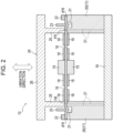
FIG. 2 is a sectional view of the vibration power generation device according to the embodiment taken along a vibration direction. -
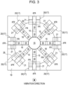
FIG. 3 is a top surface view of the vibration power generation device inFIG. 2 , with fixing implements and a push-in piece having been removed, looking from an opposite side from the side where a base is located. -
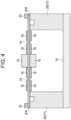
FIG. 4 is a sectional view of an article during manufacture for illustrating a step of preliminary fixing of beams in a method of manufacturing the vibration power generation device inFIG. 2 . -
FIG. 5 is a sectional view of an article during manufacture for illustrating a step of applying tension to the beams in the method of manufacturing the vibration power generation device inFIG. 2 . -
FIG. 6 is a sectional view of an article during manufacture for illustrating a step of applying tension to the beams in a method of manufacturing a variation of the vibration power generation device inFIG. 2 . -
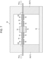
FIG. 7 is a sectional view of an article during manufacture for illustrating a step of fixing the beams in place while applying tension to the beams in a method of manufacturing a variation of the vibration power generation device inFIG. 2 . -
FIG. 8 is a sectional view of an article during manufacture for illustrating a step of cutting parts where the beams protrude after fixing of the beams in a method of manufacturing a variation of the vibration power generation device inFIG. 2 . -
FIG. 9 is a sectional view taken along a vibration direction in which another variation of the vibration power generation device inFIG. 2 and beams removed from support provided by a fixation member are illustrated next to each other. -
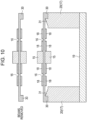
FIG. 10 is a sectional view taken along the vibration direction in which another variation of the vibration power generation device inFIG. 2 and the beam removed from support of a fixation member are illustrated next to each other. - Hereinafter, an embodiment of a vibration power generation device to which the present disclosure is applied will be described while referring to the drawings.
- As illustrated in
FIG. 1 , asensor module 11 includes a vibrationpower generation device 10 according to an embodiment of the present disclosure. Thesensor module 11 includes asensor 12, acommunication unit 13, acontroller 14, and the vibrationpower generation device 10. Thesensor module 11 detects various states and transmits the detection results to an external device without receiving power from the outside. Thesensor module 11 is, for example, used in a bridge, a train, a vehicle, a power plant, outdoor machinery, or factory equipment. - The
sensor 12 is, for example, a vibration sensor, a temperature sensor, a pressure sensor, or the like. Thesensor 12 is configured to detect any state of any detection target. Thesensor 12 is driven by power supplied from the vibrationpower generation device 10. - The
communication unit 13 includes a communication module that communicates with an external device via a network. Thecommunication unit 13, for example, transmits a detection value representing a state detected by thesensor 12 to an external device in the form of a signal. Thecommunication unit 13 may receive a command from an external device and transmit the received command to thecontroller 14. Thecommunication unit 13 is driven by power supplied from the vibrationpower generation device 10. - The
controller 14 includes one or more processors and memories. Such processors may include general-purpose processors into which specific programs are loaded to perform specific functions, and dedicated processors dedicated to specific processing. Dedicated processors may include an application specific integrated circuit (ASIC). Processors may include programmable logic devices (PLDs). PLDs may include field-programmable gate arrays (FPGAs). Thecontroller 14 may be either a system-on-a-chip (SoC) or a system-in-a-package (SiP), in which one or more processors cooperate with each other. Thecontroller 14 controls operation of thesensor 12 and thecommunication unit 13. Thecontroller 14 is driven by power supplied from the vibrationpower generation device 10. - As illustrated in
FIG. 2 , the vibrationpower generation device 10 includes aweight 15,multiple beams 16,piezoelectric members 18, and afixation member 17. - The
weight 15 provides inertial force and thereby increases the vibrations of thebeams 16 supported by thefixation member 17, as described later. Theweight 15 may be provided on surfaces of thebeams 16 located on sides in a vibration direction defined as the direction in which thebeams 16 are made to vibrate. Theweight 15 may be provided on both surfaces of eachbeam 16 in the vibration direction. - As illustrated in
FIG. 3 , themultiple beams 16 extend from theweight 15 in multiple different directions. In this embodiment, eightbeams 16 extend from theweight 15. Twobeams 16, out of themultiple beams 16, may extend from theweight 15 in straight lines in opposite directions from each other. Themultiple beams 16 may consist of a single member. As illustrated inFIG. 2 , the multiple directions in which themultiple beams 16 extend are parallel to a single virtual plane (plane). More specifically, themultiple beams 16 may extend in multiple directions along a single virtual plane. - The thickness of the
beams 16 along the vibration direction, i.e., a direction perpendicular to the previously mentioned virtual plane, may be smaller than the width of thebeams 16. Specifically, thebeams 16 may be thin plates, with the surfaces of the plates being perpendicular to the vibration direction. - The
beams 16, for example, may be formed of a metal such as stainless steel. - The
multiple beams 16 are provided with thepiezoelectric members 18. Thepiezoelectric members 18 may be disposed at positions where stress is generated by vibration of thebeams 16. Thepiezoelectric members 18 may be disposed on a plane of thebeams 16. Thepiezoelectric members 18 may be provided on surfaces of thebeams 16 on one side in the vibration direction. Multiplepiezoelectric members 18 may be provided in a line along the directions in which thebeams 16 extend. Thepiezoelectric members 18 may be provided on surfaces of thebeams 16 on both sides in the vibration direction. - The
piezoelectric members 18 are configured to each include an insulating film, a first electrode, a piezoelectric film, and a second electrode, stacked in this order from the side where thebeam 16 is located. When thebeams 16 are deformed by vibrations, thepiezoelectric members 18 deform together with thebeams 16. As a result, when thebeams 16 vibrate, stress is applied to the piezoelectric films within thepiezoelectric members 18, and this stress is converted into electric power via the piezoelectric effect of the piezoelectric films. The power generated by the piezoelectric films is output to the outside the vibrationpower generation device 10 via the first and second electrodes. - The
fixation member 17 supports themultiple beams 16 in a state where theweight 15 is suspended above a base 19 so that theweight 15 is able to vibrate in the vibration direction. The base 19 fixes supportcolumns 20, described below, in place. As illustrated inFIG. 3 , thefixation member 17 includes multiple fixing regions FR arrayed along a peripheral direction around an axis extending in the vibration direction, that is, a direction perpendicular to the previously mentioned virtual plane. In this embodiment, thefixation member 17 includesmultiple support columns 20, each of which includes a fixing region FR. Themultiple support columns 20 may be separated from each other along a peripheral direction around an axis perpendicular to the previously mentioned virtual plane. - The
fixation member 17 fixes themultiple beams 16 in place in the multiple fixing regions FR while maintaining the tension on themultiple beams 16 in a state where theweight 15 and thepiezoelectric members 18 are positioned so as to be surrounded by the multiple fixing regions FR. Thus, a state in which tension is applied to thebeams 16 from theweight 15 to the fixing regions FR is maintained. A state in which tension is maintained on themultiple beams 16 may refer to a state in which thebeams 16 are pulled taut so that the piezoelectric members are able to generate piezoelectricity in the vibrationpower generation device 10. A state in which tension is maintained on themultiple beams 16 may refer to a taut state in which theweight 15 is only capable of moving perpendicular to the virtual plane. - Tension is applied to
beams 16 using any of a variety of methods. In this embodiment, tension is applied as described below. - In this embodiment, in order to apply tension, a
recess 21 is formed in thefixation member 17 on the opposite side from theweight 15 in the directions of extension of thebeams 16 fixed to fixing regions FR from the fixing regions FR. Therecess 21 may be shaped like a groove extending along a direction perpendicular to the directions of extension of thebeams 16. Thefixation member 17 has temporary fixing regions tFR on the opposite side from theweight 15 along the extension directions from therecess 21. - The tips of
beams 16 extend radially along the previously mentioned virtual plane so as to be positioned in the fixing regions FR of thefixation member 17 of this embodiment described above. The ends of thebeams 16 on the opposite side from theweight 15 are preliminarily fixed to the temporary fixing regions tFR. The fixing may be carried out using any suitable fixing method. As illustrated inFIG. 4 , the ends ofbeams 16 may be fixed in place using fixing implements 22, such as screws, for example. - As illustrated in
FIG. 5 , with the ends of thebeams 16 fixed in place, the parts of thebeams 16 that cover therecess 21 are pushed into therecess 21 using a push-inpiece 23 from a direction perpendicular to the directions in which thebeams 16 extend. The pushing in action causes thebeams 16 to be recessed into therecess 21. With the ends of thebeams 16 fixed in place, tension is applied to thebeams 16 in the directions in which thebeams 16 extend by recessing the parts of thebeams 16 covering therecess 21. - As illustrated in
FIG. 2 , while maintaining the tension applied to thebeams 16, parts of thebeams 16, which are nearer to theweight 15 than the parts that cover therecess 21 along the directions of extension, are fixed tofixation member 17 in the fixing regions FR, which are located in the directions in which beams 16 extend. The fixing may be carried out using any suitable method. For example, thebeams 16 may be fixed in place using a fixing implement 24. The fixing implement 24 includes, for example, apressing piece 25 positioned so as to face the multiple fixing regions FR and abody 26 that can engage with thefixation member 17. The fixing implement 24 holds thebeams 16 between thepressing piece 25 and the fixing regions FR by thebody 26 engaging with thefixation member 17. -
Wiring lines 27 are disposed in thesupport columns 20. The wiring lines 27 are for providing connections to at least some of thepiezoelectric members 18 on thebeams 16. As illustrated inFIG. 3 , thewiring lines 27 formed in thesupport columns 20 are electrically connected towiring lines 28 disposed on or in thebase 19. At least some of the multiplepiezoelectric members 18 on themultiple beams 16 are connected in parallel with each other via thewiring lines 27 in thesupport columns 20 and thewiring lines 28 in thebase 19. In this embodiment, thepiezoelectric members 18 on the sides of thebeams 16 near the fixing regions FR are connected in parallel via thewiring lines 27 in thesupport columns 20 and thewiring lines 28 in thebase 19. Thepiezoelectric members 18 on the sides of thebeams 16 near theweight 15 may be connected in series or parallel by wiring lines provided in or on thebeams 16 near theweight 15 that cross other beams 16. - The
fixation member 17 is preferably formed of a material having high rigidity, for example, a single metal such as Fe, an alloy containing Fe, Ni, Cr, and so on, stainless steel, or a non-metallic substance such as a resin. - The thus-configured vibration
power generation device 10 of this embodiment includes themultiple beams 16 and thefixation member 17. Themultiple beams 16 extend from theweight 15 in multiple directions parallel to a single virtual plane and are provided with thepiezoelectric members 18. Thefixation member 17 fixes themultiple beams 16 in place in multiple fixing regions FR located along a peripheral direction around an axis extending in a direction perpendicular to a virtual plane while maintaining the tension on themultiple beams 16 in a state where theweight 15 and thepiezoelectric members 18 are positioned so as to be surrounded by the multiple fixing regions FR. In a configuration where beams extending from the weight to the perimeter are fixed separately from each other, the beams tend to flex vertically downward due to the weight. In this configuration, if the beams are flexed when not undergoing vibration, the power generated during vibration will be reduced. In contrast, in the vibrationpower generation device 10 having the above-described configuration, such flexion is reduced due to thefixation member 17 maintaining the tension on the multiple beams 16. Therefore, the vibrationpower generation device 10 is able to increase the amount of power generated because of the reduced flexion of thebeams 16. - The present invention has been described based on the drawings and examples, but note that a variety of variations and amendments may be easily made by one skilled in the art based on the present disclosure. Therefore, note that such variations and amendments are included within the scope of the present invention.
- For example, in this embodiment, tension is applied to the
beams 16 by pushing the parts of thebeams 16 covering therecess 21 using the push-inpiece 23 in a state where the ends of thebeams 16 on the opposite side from theweight 15 have been preliminarily fixed in the temporary fixing regions tFR. However, the method of applying tension to thebeams 16 is not limited to the method described in the embodiment. For example, tension can also be applied to thebeams 16 along the directions of extension using the methods described below. - As illustrated in
FIG. 6 , before manufacture of the vibrationpower generation device 10, thebeams 16 are long enough to extend beyond the fixing regions FR, which are located in radially extending directions on the virtual plane. Before manufacture of the vibrationpower generation device 10, tension is applied to thebeams 16 by pulling thebeams 16 in directions away from theweight 15 along the directions of extension. As illustrated inFIG. 7 , the parts of thebeams 16 covering the fixing regions FR are fixed to thefixation member 17 while maintaining the tension applied to thebeams 16. The fixing may be carried out using any suitable method. For example, similarly to as in this embodiment, thebeams 16 may be fixed in place using the fixing implement 24. After being fixed in place, the parts of thebeams 16 protruding beyond thefixation member 17 may be cut off, as illustrated inFIG. 8 . - As illustrated in
FIG. 9 , for example, tension may be applied to thebeams 16 along the directions of extension by inserting fixingpieces 29 formed in the fixing regions FR into holes HL formed in thebeams 16. The fixingpieces 29 protrude perpendicular to the virtual plane. The tip of each fixingpiece 29 may slope outward in a direction from theweight 15 towards the fixingpiece 29. The tips of the fixingpieces 29 may be hemispherical for example. The distance from theweight 15 to the outer side of the inner surface defining each hole HL in a state where thebeams 16 have been removed from support provided by thefixation member 17 may be shorter than in the state where thebeams 16 are supported by thefixation member 17. For example, the above-described configuration can be realized by making the distance from theweight 15 to the outer surface of each fixingpiece 29 on the outside in the direction towards the hole HL longer than the distance from theweight 15 to the outer side of the inner surface defining the hole HL when thebeams 16 are removed from the support provided by thefixation member 17. - As illustrated in
FIG. 10 , for example, tension may be applied to thebeams 16 along the directions of extension by forming engagingportions 31, in the fixing regions FR, that engage with engagingportions 30 of thebeams 16 in the directions of extension of thebeams 16. The distance from theweight 15 to the engagingportions 30 in a state where thebeams 16 have been removed from support provided by thefixation member 17 may be shorter than that distance in a state where thebeams 16 are supported by thefixation member 17. For example, the above-described configuration can be realized by making the distance from theweight 15 to the engagingportions 31 longer than the distance from theweight 15 to the engagingportions 30 when thebeams 16 have been removed from support provided by thefixation member 17. The distance from theweight 15 to each engagingportion 31 is the distance between theweight 15 and the point in the engagingportion 31 where pressure is received in a direction from the engagingportion 30 towards theweight 15. The distance from theweight 15 to each engagingportion 30 is the distance between theweight 15 and the point in the engagingportion 30 where pressure is received in an opposite direction from the direction from the engagingportion 31 towards theweight 15. -
- 10 vibration power generation device
- 11 sensor module
- 12 sensor
- 13 communication unit
- 14 controller
- 15 weight
- 16 beam
- 17 fixation member
- 18 piezoelectric member
- 19 base
- 20 support column
- 21 recess
- 22 fixing implement
- 23 push-in piece
- 24 fixing implement
- 25 pressing piece
- 26 body
- 27 wiring line
- 28 wiring line
- 29 fixing piece
- 30 engaging portion
- 31 engaging portion
- HL hole
- FR fixing region
- tFR temporary fixing region
Claims (8)
- A vibration power generation device comprising:a weight;multiple beams extending from the weight in multiple directions parallel to a single plane;piezoelectric members respectively provided on the multiple beams; anda fixation member configured to fix the multiple beams in place in multiple fixing regions located along a peripheral direction around an axis perpendicular to the plane when the weight and the piezoelectric members are positioned with the weight and the piezoelectric members surrounded by the multiple fixing regions while maintaining tension acting on the multiple beams.
- The vibration power generation device according to claim 1,wherein a recess is formed, in the fixation member, on an opposite side from the weight along directions of extension of the beams that are fixed to a fixing region from the fixing region, andthe beams are recessed into the recess.
- The vibration power generation device according to claim 1,wherein the fixing regions include fixing pieces protruding perpendicular to the plane, andthe beams include holes into which the fixing pieces are inserted.
- The vibration power generation device according to claim 1,
wherein the fixing regions and the beams are equipped with engaging portions that are configured to engage with each other in directions of extension of the beams. - The vibration power generation device according to any one of claims 1 to 3,wherein the fixation member includes multiple support columns, the support columns being separated from each other along a peripheral direction around an axis perpendicular to the plane, and the support columns respectively including the fixing regions, andat least some of the multiple piezoelectric members provided on the multiple beams are connected in series or parallel with each other via wiring lines provided on or in the support columns and on or in a base configured to fix the support columns in place.
- A sensor module comprising:the vibration power generation device according to any one of claims 1 to 5;a sensor configured to be driven by power supplied from the vibration power generation device;a communication unit configured to be driven by power supplied from the vibration power generation device and to communicate with an external device; anda controller configured to be driven by power supplied from the vibration power generation device and to control the sensor and the communication unit.
- The sensor module according to claim 6,
wherein the sensor module is configured to be used in a bridge, a train, a vehicle, a power plant, outdoor machinery, or factory equipment. - A vibration power generation device manufacturing method comprising: making the beams extend radially on a plane and applying tension to multiple beams in a direction of extension of each beam; and
fixing the multiple beams to a fixation member in fixing regions located in directions in which the beams radially extend while maintaining the tension on the beams.
Applications Claiming Priority (2)
| Application Number | Priority Date | Filing Date | Title |
|---|---|---|---|
| JP2020142106A JP7557311B2 (en) | 2020-08-25 | 2020-08-25 | Vibration power generation device, sensor module and manufacturing method |
| PCT/JP2021/031035 WO2022045150A1 (en) | 2020-08-25 | 2021-08-24 | Vibration power generation device, sensor module, and manufacturing method |
Publications (2)
| Publication Number | Publication Date |
|---|---|
| EP4207577A1 true EP4207577A1 (en) | 2023-07-05 |
| EP4207577A4 EP4207577A4 (en) | 2024-10-09 |
Family
ID=80353719
Family Applications (1)
| Application Number | Title | Priority Date | Filing Date |
|---|---|---|---|
| EP21861574.8A Withdrawn EP4207577A4 (en) | 2020-08-25 | 2021-08-24 | Vibration power generation device, sensor module, and manufacturing method |
Country Status (5)
| Country | Link |
|---|---|
| US (1) | US20230361694A1 (en) |
| EP (1) | EP4207577A4 (en) |
| JP (1) | JP7557311B2 (en) |
| CN (1) | CN115989628A (en) |
| WO (1) | WO2022045150A1 (en) |
Families Citing this family (1)
| Publication number | Priority date | Publication date | Assignee | Title |
|---|---|---|---|---|
| JP7379296B2 (en) * | 2020-08-25 | 2023-11-14 | 京セラ株式会社 | Vibration power generation device and sensor module |
Family Cites Families (6)
| Publication number | Priority date | Publication date | Assignee | Title |
|---|---|---|---|---|
| JP3790255B1 (en) | 2005-03-07 | 2006-06-28 | 太平洋セメント株式会社 | ENERGY CONVERSION DEVICE, MOBILE BODY HAVING THE SAME, AND ENERGY CONVERSION SYSTEM |
| US8912710B2 (en) * | 2011-02-20 | 2014-12-16 | Omnitek Partners Llc | Energy harvesting from input impulse with motion doubling mechanism for generating power from mortar tube firing impulses and other inputs |
| JP5931472B2 (en) | 2012-01-30 | 2016-06-08 | 株式会社ミツバ | Power generator |
| JP7395150B2 (en) * | 2015-09-02 | 2023-12-11 | 大日本印刷株式会社 | Power generation device and power generation method |
| CN105396257A (en) * | 2015-11-23 | 2016-03-16 | 左招霞 | Power generation bounding bed |
| JP7285424B2 (en) | 2019-01-29 | 2023-06-02 | 住友金属鉱山株式会社 | Method for manufacturing vibration power generation device and method for manufacturing magnetostrictive part |
-
2020
- 2020-08-25 JP JP2020142106A patent/JP7557311B2/en active Active
-
2021
- 2021-08-24 CN CN202180052572.2A patent/CN115989628A/en active Pending
- 2021-08-24 EP EP21861574.8A patent/EP4207577A4/en not_active Withdrawn
- 2021-08-24 US US18/042,774 patent/US20230361694A1/en active Pending
- 2021-08-24 WO PCT/JP2021/031035 patent/WO2022045150A1/en not_active Ceased
Also Published As
| Publication number | Publication date |
|---|---|
| JP7557311B2 (en) | 2024-09-27 |
| EP4207577A4 (en) | 2024-10-09 |
| US20230361694A1 (en) | 2023-11-09 |
| WO2022045150A1 (en) | 2022-03-03 |
| JP2022037788A (en) | 2022-03-09 |
| CN115989628A (en) | 2023-04-18 |
Similar Documents
| Publication | Publication Date | Title |
|---|---|---|
| US5811693A (en) | Force detector and acceleration detector and method of manufacturing the same | |
| KR100369908B1 (en) | Piezoelectric Acoustic Component | |
| US6711024B1 (en) | Flexible microsystem and building techniques | |
| US9850123B2 (en) | Stress relief MEMS structure and package | |
| US9585253B2 (en) | Electronic device | |
| KR102773571B1 (en) | Method for manufacturing contact plate for battery stack, contact plate for battery stack and battery stack | |
| US7936109B1 (en) | Non-resonant energy harvesting devices and methods | |
| EP4207577A1 (en) | Vibration power generation device, sensor module, and manufacturing method | |
| CN103814586B (en) | Directional loudspeaker | |
| KR102332884B1 (en) | torque detector | |
| US9503048B2 (en) | Piezoelectric vibrating reed and piezoelectric vibrator | |
| CN111649767B (en) | A split piezoelectric sensor | |
| KR101067019B1 (en) | Energy Harvester Unit Module, Multi-Axis Energy Harvester Assembly Made By Combining It, Multi-Axis Energy Harvester Multiple Assembly Made By Combining It | |
| EP2728904A1 (en) | Vibrating element and method for producing vibrating element | |
| WO2022045148A1 (en) | Vibration power generation device, sensor module, and manufacturing method | |
| US20120267153A1 (en) | Coupling device, assembly having a coupling device, and method for producing an assembly having a coupling device | |
| US20160365501A1 (en) | Curved piezoelectric device | |
| US9032608B2 (en) | Method for manufacturing at least one mechanical-electrical energy conversion system | |
| EP4207576A1 (en) | Vibration power generation device and sensor module | |
| JP2006035003A (en) | Ultrasonic transducer and method for manufacturing ultrasonic transducer | |
| CN107645698B (en) | Diaphragm material for diaphragm of sound production device and diaphragm | |
| JP2025007460A (en) | Vibration power generation device and sensor module | |
| JP2017108379A (en) | Piezoelectric vibrator |
Legal Events
| Date | Code | Title | Description |
|---|---|---|---|
| STAA | Information on the status of an ep patent application or granted ep patent |
Free format text: STATUS: THE INTERNATIONAL PUBLICATION HAS BEEN MADE |
|
| PUAI | Public reference made under article 153(3) epc to a published international application that has entered the european phase |
Free format text: ORIGINAL CODE: 0009012 |
|
| STAA | Information on the status of an ep patent application or granted ep patent |
Free format text: STATUS: REQUEST FOR EXAMINATION WAS MADE |
|
| 17P | Request for examination filed |
Effective date: 20230224 |
|
| AK | Designated contracting states |
Kind code of ref document: A1 Designated state(s): AL AT BE BG CH CY CZ DE DK EE ES FI FR GB GR HR HU IE IS IT LI LT LU LV MC MK MT NL NO PL PT RO RS SE SI SK SM TR |
|
| DAV | Request for validation of the european patent (deleted) | ||
| DAX | Request for extension of the european patent (deleted) | ||
| A4 | Supplementary search report drawn up and despatched |
Effective date: 20240910 |
|
| RIC1 | Information provided on ipc code assigned before grant |
Ipc: H10N 30/88 20230101ALI20240904BHEP Ipc: H10N 30/30 20230101ALI20240904BHEP Ipc: H02N 2/18 20060101AFI20240904BHEP |
|
| STAA | Information on the status of an ep patent application or granted ep patent |
Free format text: STATUS: THE APPLICATION IS DEEMED TO BE WITHDRAWN |
|
| 18D | Application deemed to be withdrawn |
Effective date: 20250328 |