EP4207484A1 - Cavity filter for antenna - Google Patents
Cavity filter for antenna Download PDFInfo
- Publication number
- EP4207484A1 EP4207484A1 EP21862051.6A EP21862051A EP4207484A1 EP 4207484 A1 EP4207484 A1 EP 4207484A1 EP 21862051 A EP21862051 A EP 21862051A EP 4207484 A1 EP4207484 A1 EP 4207484A1
- Authority
- EP
- European Patent Office
- Prior art keywords
- resonant bar
- circumferential surface
- resonant
- cavity
- tolerance management
- Prior art date
- Legal status (The legal status is an assumption and is not a legal conclusion. Google has not performed a legal analysis and makes no representation as to the accuracy of the status listed.)
- Pending
Links
Images








Classifications
-
- H—ELECTRICITY
- H01—ELECTRIC ELEMENTS
- H01P—WAVEGUIDES; RESONATORS, LINES, OR OTHER DEVICES OF THE WAVEGUIDE TYPE
- H01P7/00—Resonators of the waveguide type
- H01P7/04—Coaxial resonators
-
- H—ELECTRICITY
- H01—ELECTRIC ELEMENTS
- H01P—WAVEGUIDES; RESONATORS, LINES, OR OTHER DEVICES OF THE WAVEGUIDE TYPE
- H01P1/00—Auxiliary devices
- H01P1/20—Frequency-selective devices, e.g. filters
- H01P1/207—Hollow waveguide filters
- H01P1/208—Cascaded cavities; Cascaded resonators inside a hollow waveguide structure
-
- H—ELECTRICITY
- H01—ELECTRIC ELEMENTS
- H01P—WAVEGUIDES; RESONATORS, LINES, OR OTHER DEVICES OF THE WAVEGUIDE TYPE
- H01P1/00—Auxiliary devices
- H01P1/20—Frequency-selective devices, e.g. filters
- H01P1/207—Hollow waveguide filters
-
- H—ELECTRICITY
- H01—ELECTRIC ELEMENTS
- H01Q—ANTENNAS, i.e. RADIO AERIALS
- H01Q11/00—Electrically-long antennas having dimensions more than twice the shortest operating wavelength and consisting of conductive active radiating elements
- H01Q11/12—Resonant antennas
- H01Q11/14—Resonant antennas with parts bent, folded, shaped or screened or with phasing impedances, to obtain desired phase relation of radiation from selected sections of the antenna or to obtain desired polarisation effect
Definitions
- the present disclosure relates to a cavity filter for an antenna, and more particularly, to a cavity filter for an antenna, which can extend a design tolerance range relating to a part within a cavity.
- a multiple input multiple output (MIMO) technology is a technology for significantly increasing a data transmission capacity by using multiple antennas, and is a spatial multiplexing scheme in which a transmitter transmits different data through transmission antennas and a receiver distinguishes between the transmission data through proper signal processing. Accordingly, as the number of transmission antennas and the number of reception antennas are simultaneously increased, more data can be transmitted because a channel capacity is increased. For example, if the number of antennas is increased to 10, about a 10-times channel capacity is secured compared to a current single antenna system by using the same frequency band.
- An RF filter having a cavity structure has a characteristic in that a resonator consisting of a resonant post (or a resonant bar), etc., that is, a conductor, is provided within a box structure formed of a metallic conductor and the RF filter transmits only a characteristic frequency of an ultra high frequency by resonance because only an electromagnetic field having a unique frequency is present in the cavity.
- a bandpass filter having such a cavity structure has a low insertion loss and is advantageous for high output, and is variously used as a filter for a mobile communication base station antenna.
- the RF filter having a cavity structure has a problem in that a resonator provided within a cavity needs to be precisely manufactured within a design tolerance range (i.e., a variable range of a tuning design) upon manufacturing of the resonator, in performing a frequency tuning design within the cavity.
- a design tolerance range i.e., a variable range of a tuning design
- the resonator (a resonant bar) has been manufactured out of the design tolerance range, there is a problem in that the resonator needs to be post-processed so that the resonator falls within a frequency tuning design range upon actual frequency tuning of the cavity.
- the present disclosure has been made to solve the problems, and an object of the present disclosure is to provide a cavity filter for an antenna, which can extend a tolerance range upon manufacturing of a resonator and facilitates a frequency tuning design within a cavity.
- An embodiment of the cavity filter for an antenna includes a filter body having one side opened and having multiple cavities partitioned by barrier ribs, a resonant bar installed in each of the multiple cavities, a resonant bar boss having a part of the resonant bar inserted therein and provided so that the resonant bar is installed in the cavity, and a tolerance management stopper part disposed between an inner circumferential surface of the resonant bar boss and an outer circumferential surface of the resonant bar and configured to perform a moving and stop function in an insertion direction of the resonant bar upon resonant design of the cavity.
- the resonant bar boss may protrude in the one direction from the bottom of the cavity, and may be formed in a circular pipe shape having an empty inside.
- the cavity filter may further include a solder part hardened after being applied to a front end of the resonant bar boss, when the resonant bar is temporarily fixed at a design location according to the resonant design by the tolerance management stopper part.
- solder part may be applied and hardened so that the tolerance management stopper part is hidden from the outside.
- the tolerance management stopper part may be integrally formed on the outer circumferential surface of the resonant bar that is inserted into the inner circumferential surface of the resonant bar boss.
- the tolerance management stopper part may have a wrinkled shape. At least the diameter of an outer circumferential surface of the tolerance management stopper part that comes into contact with the inner circumferential surface of the resonant bar boss may be formed to have a size in which the outer circumferential surface of the tolerance management stopper part is forcedly fitted into the inner circumferential surface of the resonant bar boss.
- the tolerance management stopper part may be a friction member disposed between the inner circumferential surface of the resonant bar boss and the outer circumferential surface of the resonant bar.
- the friction member may include a wrinkle part that is interposed in the outer circumferential surface of the resonant bar and that has the outside pressurizing the inner circumferential surface of the resonant bar boss and the inside pressurizing the outer circumferential surface of the resonant bar.
- the friction member may further include multiple incision parts formed by incising one side of the wrinkle part so that the multiple incision parts are spaced apart from each other in a circumferential direction thereof.
- the friction member may further include a support plate part integrally formed on the other side of the wrinkle part and provided to surround a front end of the resonant bar along with the wrinkle part.
- the resonant bar boss may be formed in a cylindrical shape that protrudes in the one direction from the bottom of the cavity.
- the tolerance management stopper part may have a wrinkled shape. At least the diameter of an inner circumferential surface of the tolerance management stopper part that comes into contact with the outer circumferential surface of the resonant bar boss may be formed to have a size in which the outer circumferential surface of the tolerance management stopper part is forcedly fitted into the outer circumferential surface of the resonant bar boss.
- the tolerance management stopper part may be a friction member disposed between the outer circumferential surface of the resonant bar boss and the inner circumferential surface of the resonant bar.
- the friction member may include a wrinkle part that is interposed in the inner circumferential surface of the resonant bar and that has the outside pressurizing the inner circumferential surface of the resonant bar and the inside pressurizing the outer circumferential surface of the resonant bar boss.
- the friction member may further include a support plate part integrally formed on the other side of the wrinkle part and provided to surround one end of the resonant bar boss along with the wrinkle part, and multiple incision parts configured to divide a part of the end of an edge of the support plate part and the wrinkle part in a way to be separated from each other in a circumferential direction thereof.
- the resonant bar boss may be formed in a cylindrical shape having the diameter gradually reduced in the one direction from the bottom of the cavity.
- the tolerance management stopper part may be formed in a rib shape that protrudes in a central direction thereof from the inner circumferential surface of the resonant bar, wherein multiple protrusion ribs provided to be spaced apart from each other in a cylindrical direction may be integrally formed on the inner circumferential surface of the resonant bar.
- the cavity filter may further include a filter cover configured to cover the opened one side of the cavity.
- the resonant design for the cavity space may be performed while repeatedly moving and stopping the resonant bar in a state in which the tolerance management stopper part has been installed, by using an external press-fitting member that has been inserted therethrough through a design hole for a cover for design that performs a cover function identical with a cover function of the filter cover and in which a predetermined design hole has been formed.
- the resonant bar can be manufactured to have a thin thickness because the resonant bar has only to be manufactured to have weight which can be supported by the solder part.
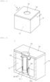
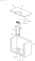
- FIG. 1 is a mimetic diagram of an outward appearance illustrating a part of a cavity filter for an antenna according to the present disclosure.
- FIG. 2 is a cutaway perspective view taken along line A-A in FIG. 1 , and is a cutaway perspective view illustrating a first embodiment of a tolerance management stopper part, among components of the cavity filter for an antenna, according to an embodiment of the present disclosure.
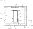
- FIG. 3 is a cross-sectional view taken along line A-A in FIG. 1 .
- FIG. 4 is a cutaway exploded perspective view taken along line A-A in FIG. 1 .
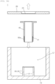
- FIGS. 5A to 5C are cross-sectional exploded views illustrating the order in which a resonant bar is installed within a cavity.
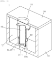
- FIG. 6 is a cutaway perspective view taken along line A-A in FIG. 1 , and is a cutaway perspective view illustrating a second embodiment of the tolerance management stopper part, among the components of the cavity filter for an antenna according to an embodiment of the present disclosure.
- FIG. 7 is a cross-sectional view of FIG. 6 .
- FIG. 8 is an incised and exploded perspective view of FIG. 6 .
- FIG. 9 is a cutaway perspective view taken along line A-A in FIG. 1 , and is a cutaway perspective view illustrating a third embodiment of the tolerance management stopper part, among the components of the cavity filter for an antenna according to an embodiment of the present disclosure.
- FIG. 10 is a cross-sectional view of FIG. 9 .
- FIG. 11 is an incised and exploded perspective view of FIG. 9 .
- FIG. 12 is a cutaway perspective view taken along line A-A in FIG. 1 , and is a cutaway perspective view illustrating a fourth embodiment of the tolerance management stopper part, among the components of the cavity filter for an antenna according to an embodiment of the present disclosure.
- FIG. 13 is a cross-sectional view of FIG. 12 .
- FIG. 14 is an incised and exploded perspective view of FIG. 6 .
- FIG. 15 is a cutaway perspective view taken along line A-A in FIG. 1 , and is a cutaway perspective view illustrating a fifth embodiment of the tolerance management stopper part, among the components of the cavity filter for an antenna according to an embodiment of the present disclosure.
- FIG. 12 is a cutaway perspective view taken along line A-A in FIG. 1 , and is a cutaway perspective view illustrating a fifth embodiment of the tolerance management stopper part, among the components of the cavity filter for an antenna according to an embodiment of the present disclosure.
- FIG. 16 is a cross-sectional view of FIG. 15 .
- FIG. 17 is an incised and exploded perspective view of FIG. 15 .
- 1 cavity filter for antenna 10: filter body 20: filter cover 25: engraving part 30,30-T, 30-P: resonant bar boss 31-I: inner circumferential surface of resonant bar boss 31-O: outer circumferential surface of resonant bar boss 40: resonant bar 41: stopper part installation stage 50: tolerance management stopper part 51a: external diameter 52a: internal diameter 60: solder part 70: cover for design 80: external press-fitting member C: cavity
- FIG. 1 is a mimetic diagram of an outward appearance illustrating a part of a cavity filter for an antenna according to the present disclosure.
- FIG. 2 is a cutaway perspective view taken along line A-A in FIG. 1 .
- FIG. 3 is a cross-sectional view taken along line A-A in FIG. 1 .
- FIG. 4 is a cutaway exploded perspective view taken along line A-A in FIG. 1 .
- An embodiment 1 of the cavity filter for an antenna according to the present disclosure includes a filter body 10 having a cavity C having one side opened and a filter cover 20 disposed to cover the opened one side of the cavity C of the filter body 10, as referenced in FIGS. 1 to 4 .
- Multiple cavities C partitioned by barrier ribs not illustrated may be formed in the filter body 10.
- the multiple cavities C may be designed through a frequency tuning design so that only respective specific frequencies pass through the multiple cavities.
- only one cavity C has been diagrammed.
- the diagrammed unit cavity C may be continuously provided in a plural number, thus forming the filter body 10. Therefore, it has only to be understood that a component that partitions the cavities C, among components of the filter body 10, can function as the barrier rib.
- the filter body 10 may be generally formed of a dielectric material.
- the filter body 10 may be provided so that only an electromagnetic field having a unique frequency within the cavity C is present by forming a film of a metallic material on all of an inner surface that forms the cavity C and a portion that forms an outward appearance of the cavity C.
- each cavity C that is provided in the filter body 10 may be formed in a different form depending on a design value of a specific frequency. As described later, however, description is given based on the premise that both a resonant bar 40 and a resonant bar boss 30 for installing the resonant bar 40 are essentially provided.
- the embodiment 1 of the cavity filter for an antenna according to the present disclosure may further include the resonant bar 40 installed in each of the multiple cavities C, and the resonant bar boss 30 into which a part of the resonant bar 40 is inserted and that is provided so that the resonant bar 40 is installed in the cavity C, as referenced in FIG. 1 to 4 .
- the resonant bar 40 is provided as a metallic material, and is one of major components of the filter in which a frequency tuning design is performed along a space (or a separation distance) between the resonant bar 40 and the filter cover 20 within the cavity C.
- frequency tuning may be performed through the adjustment of a distance between the resonant bar 40 and an inner surface of the filter cover 20, which is changed depending on the height from a closed bottom of the cavity C formed in the filter body 10 to the opened one side of the cavity C.
- a part of the front end of the resonant bar 40 on the other side thereof may be inserted and fixed to the resonant bar boss 30 provided at the bottom of the cavity C of the filter body 10.
- a separation distance between the front end of the resonant bar 40 on one side thereof and the filter cover 20 may be changed based on the amount of the resonant bar 40 that is inserted into the resonant bar boss 30.
- the frequency tuning design may be decided based on the changed separation distance.
- the resonant bar boss 30, 30-T(tube) has been provided so that the resonant bar 40 is installed within the cavity C as described above.
- the resonant bar boss may be formed in an approximately circular pipe shape the inside of which is empty.
- the resonant bar boss 30, 30-T may be formed integrally with the filter body 10 within the cavity C when the filter body 10 is manufactured by using a mold.
- the resonant bar boss 30 does not need to be essentially formed integrally with the filter body 10, and may be manufactured separately from the filter body 10 and coupled within the cavity C of the filter body 10 in a way to be detachable from the filter body 10. Furthermore, the resonant bar boss 30 does not need to be essentially formed in the circular pipe shape. As in other embodiments (a fourth embodiment and a fifth embodiment) of a tolerance management stopper part, which have been referenced in FIGS. 12 to 17 described later, among the components of the cavity filter for an antenna according to an embodiment of the present disclosure, the resonant bar boss 30 may be provided in a cylindrical shape that protrudes in the opened one direction from the bottom of the cavity C (refer to FIGS.
- a lower end of the resonant bar 40 may be fitted and coupled to surround the outer circumferential surface of one end of the resonant bar boss 30-P having the cylindrical shape. This is more specifically described later.
- the embodiment 1 of the cavity filter for an antenna according to the present disclosure may further include a tolerance management stopper part 50a as referenced in FIGS. 2 to 4 .
- the tolerance management stopper part 50a referenced in FIGS. 2 to 4 is named a "tolerance management stopper part according to a first embodiment".
- the reference numeral is indicated as "50a" in order to distinguish between the reference numeral and those in a second embodiment and a third embodiment described later.
- the tolerance management stopper part 50a according to the first embodiment may be disposed between an inner circumferential surface 31-I(In) of the resonant bar boss 30-T and an outer circumferential surface of the resonant bar 40.
- the tolerance management stopper part 50a according to the first embodiment performs a role of performing a moving and stop function in the insertion direction of the resonant bar 40 upon resonant design of the cavity C.
- the resonant bar 40 may be fixed within the cavity C of the filter body 10 in a way to be movable with respect to the resonant bar boss 30-T.
- the tuning of the resonant frequency is performed by an operation of the resonant bar 40 moving within the cavity C through the medium of the resonant bar boss 30-T as described above.
- the tolerance management stopper part 50a is moved when a resonant designer applies a predetermined external force or higher for the tuning of the resonant frequency, and plays a role of performing temporary fixing by being stopped with respect to the resonant bar boss 30-T when the external force is released.
- the embodiment 1 of the cavity filter for an antenna according to the present disclosure can extend a design tolerance of the resonant bar 40 compared to a conventional technology because the tolerance management stopper part 50a according to the first embodiment is provided. That is, by further extending a preset design tolerance range, a precise manufacturing design is not required upon manufacturing of the resonant bar 40, and a process of post-processing the resonant bar 40 in tuning a resonant frequency within the cavity C can be obviated.
- the embodiment 1 of the cavity filter for an antenna according to the present disclosure may further include a solder part 60 that fully fixes the resonant bar 40 as the solder part 60 is applied at the front end of the resonant bar boss 30-T and then hardened, when the resonant bar 40 is temporarily fixed at a design location according to a resonant design by the tolerance management stopper part 50a according to the first embodiment, as referenced in FIGS. 2 to 4 .
- the tolerance management stopper part 50a may complete the function of temporarily fixing the resonant bar 40 at a predetermined location of the resonant bar boss 30-T according to a resonant frequency tuning design as described above.
- the resonant bar 40 may be fully fixed at the temporally fixed location of the resonant bar boss 30-T by the solder part 60.
- the solder part 60 may be applied and hardened so that the tolerance management stopper part 50a according to the first embodiment is hidden from the outside. Any material may be adopted as the solder part 60 as long as the material enables the tolerance management stopper part 50a according to the first embodiment to be hidden from the outside and does not affect a resonant frequency tuning design within the cavity C.
- a meltable lead material may be adopted as the solder part 60, and a common adhesive material may also be adopted as the solder part 60.
- the solder part 60 may be applied and hardened at a step portion formed by the front end of the resonant bar boss 30-T and the outer circumferential surface of the resonant bar 40 in a ring shape, thus firmly fixing the resonant bar 40 to the resonant bar boss 30-T.
- the tolerance management stopper part 50a according to the first embodiment may be integrally formed on the outer circumferential surface of the resonant bar 40 that is inserted into the inner circumferential surface 31-I of the resonant bar boss 30-T (refer to the second embodiment and the third embodiment referenced in FIGS. 6 to 8 described later).
- the tolerance management stopper part 50a according to the first embodiment may be forcedly fitted and coupled to the inside of the resonant bar boss 30-T, after being manufactured as a separate component and previously (first) coupled to the resonant bar boss 30 (refer to the third embodiment referenced in FIGS. 1 to 4 and FIGS. 9 to 11 described later). That is, the tolerance management stopper part 50a according to the first embodiment may be a friction member that is disposed between the inner circumferential surface 31-I of the resonant bar boss 30-T and the outer circumferential surface of the resonant bar 40.
- the second embodiment and second embodiment of the tolerance management stopper part 50a are more specifically described later.
- FIGS. 5A to 5C are cross-sectional exploded views illustrating the order in which the resonant bar 40 is installed within the cavity C.
- a form in which the resonant bar 40 is installed within the cavity C is briefly described as follows with reference to FIGS. 5A to 5C .
- FIG. 5A is the state in which the filter cover 20 has been removed from the filter body 10.
- the tolerance management stopper part 50a according to the first embodiment has been provided in the front end of the resonant bar 40 on the other side thereof, the resonant bar 40 is disposed over the opened top of the resonant bar boss 30-T.
- a part of the front end of the resonant bar 40 on the other side thereof is forcedly fitted and coupled to the inside of the resonant bar boss 30-T.
- an external force that is provided by an assembler a resonant frequency tuning designer
- the tolerance management stopper part 50a which is integrally provided at the front end of the resonant bar 40 on the other side thereof or provided as a separate component coupled thereto
- the resonant bar 40 may be moved along the resonant bar boss 30-T and may be stopped and temporarily fixed at an arbitrary location when the external force of the assembler is removed.
- the solder part 60 is applied to a step portion that is formed by the front end of the resonant bar boss 30-T and the resonant bar 40 in a ring shape, and is applied and then hardened so that the tolerance management stopper part 50a according to the first embodiment is hidden from the outside, so that the resonant bar 40 can be firmly fixed at a tuning-designed location of a resonant frequency.
- the resonant bar 40 has an advantage in that the resonant bar 40 can be manufactured at a thinner thickness compared to a conventional technology because the resonant bar 40 can be manufactured with weight by which the resonant bar 40 has only to be fixed by the solder part 60 without being detached. If the thickness of the resonant bar 40 is thin, a production cost can be naturally reduced.
- a tuning design for a resonant frequency within the cavity C may be primarily performed.
- a cover for design 70 that performs the same cover function as the filter cover 20 is installed instead of the filter cover 20.
- the primary tuning design for the resonant frequency is performed by repeatedly moving the resonant bar 40 by applying a predetermined external force or higher to the resonant bar 40 in the state of FIG.
- a secondary tuning design for the resonant frequency may be precisely performed by an operation of performing engraving on an engraving part 25 that has been formed in the filter cover 20 by using a predetermined engraving tool on the outside so that a change in the shape of the filter cover 20 according to the engraving within the cavity C is incorporated.
- FIG. 6 is a cutaway perspective view taken along line A-A in FIG. 1 , and is a cutaway perspective view illustrating the second embodiment of the tolerance management stopper part, among the components of the cavity filter for an antenna according to an embodiment of the present disclosure.
- FIG. 7 is a cross-sectional view of FIG. 6 .
- FIG. 8 is an incised and exploded perspective view of FIG. 6 .
- the tolerance management stopper part 50a according to the first embodiment has been provided as a component that is manufactured separately from the resonant bar 40 and that is interposed between the inner circumferential surface 31-I of the resonant bar boss 30-T and the outer circumferential surface of the resonant bar 40 for the primary tuning design for the resonant frequency within the cavity C, as referenced in FIGS. 2 to 4 .
- the tolerance management stopper part 50a according to the first embodiment does not need to be essentially manufactured as a separate component.
- a tolerance management stopper part 50b according to the second embodiment may be integrally formed on the outer circumferential surface of the resonant bar 40 (in particular, the outer circumferential surface of the front end of the resonant bar 40 on the other side thereof) that is inserted into the inner circumferential surface 31-I of the resonant bar boss 30-T.
- the tolerance management stopper part 50 referenced in FIGS. 2 to 4 is named “the tolerance management stopper part 50a according to the first embodiment”
- the tolerance management stopper part 50b referenced in FIGS. 6 to 8 is named “the tolerance management stopper part 50b according to the second embodiment", for convenience of description.
- Each of the tolerance management stopper part 50a according to the first embodiment and the tolerance management stopper part 50b according to the second embodiment has a wrinkled shape, as referenced in FIGS. 4 and 8 , but at least the diameter of an outer circumferential surface of the tolerance management stopper part that comes into contact with the inner circumferential surface 31-I of the resonant bar boss 30-T may be formed to have a size in which the outer circumferential surface of the tolerance management stopper par is forcedly fitted into the inner circumferential surface 31-I of the resonant bar boss 30-T.
- the tolerance management stopper part 50a may include a wrinkle part 50a-1 that is interposed in the outer circumferential surface of the resonant bar 40, but the outside of the wrinkle part pressurizes the inner circumferential surface 31-I of the resonant bar boss 30-T and the inside thereof pressurizes the outer circumferential surface of the resonant bar 40.
- an internal diameter 52a of an inner circumferential surface that belongs to a wrinkled shape of the wrinkle part 50a-1 and that comes into contact with at least the outer circumferential surface of the resonant bar 40 is formed to have a size in which the inner circumferential surface of the wrinkle part is forcedly fitted into the outer circumferential surface of the resonant bar 40.
- an external diameter 51a of an outer circumferential surface that belongs to the wrinkled shape of the wrinkle part 50a-1 and that comes into contact with at least the inner circumferential surface 31-I of the resonant bar boss 30-T is formed to have a size in which the inner circumferential surface of the wrinkle part is forcedly fitted into the inner circumferential surface 31-I of the resonant bar boss 30-T.
- the tolerance management stopper part 50a when the tolerance management stopper part 50a according to the first embodiment is coupled to the resonant bar 40, after the tolerance management stopper part is forcedly fitted into the resonant bar 40 and firmly closely attached thereto due to the size of the internal diameter 52a of the tolerance management stopper part, the tolerance management stopper part is firmly closely attached to the inner circumferential surface 31-I of the resonant bar boss 30-T by being forcedly fitted into and coupled to the inner circumferential surface 31-I thereof due to the size of the external diameter 51a. Accordingly, the temporary fixing of the tolerance management stopper part 50a according to a predetermined frictional force is performed.
- the tolerance management stopper part 50b according to the second embodiment is integrally formed in the resonant bar 40 as referenced in FIGS. 6 to 8 . Accordingly, a slip problem with the resonant bar 40 does not occur, and the tolerance management stopper part is forcedly fitted and coupled to the inner circumferential surface 31-I of the resonant bar boss 30-T by the size of the external diameter thereof. Accordingly, the tolerance management stopper part can be configured to be temporarily fixed according to a predetermined frictional force.
- FIG. 9 is a cutaway perspective view taken along line A-A in FIG. 1 , and is a cutaway perspective view illustrating the third embodiment of the tolerance management stopper part, among the components of the cavity filter for an antenna according to an embodiment of the present disclosure.
- FIG. 10 is a cross-sectional view of FIG. 9 .
- FIG. 11 is an incised and exploded perspective view of FIG. 9 .
- a tolerance management stopper part 50c according to the third embodiment as a modified example of the tolerance management stopper part 50a according to the first embodiment.
- the tolerance management stopper part 50c may include a wrinkle part 50c-1 that is interposed in the outer circumferential surface of the resonant bar 40, and that has the outside pressurizes the inner circumferential surface 31-I of the resonant bar boss 30-T and the inside pressurizing the outer circumferential surface of the resonant bar 40, multiple incision parts 50c-2 formed by incising one side of the wrinkle part 50c-1 so that the multiple incision parts 50c-2 are spaced apart from each other in a circumferential direction thereof, and a support plate part 50c-3 integrally formed on the other side of the wrinkle part 50c-1 and provided to surround the front end of the resonant bar 40 along with the wrinkle part 50c-1.
- the one side of the wrinkle part 50c-1 means a direction in which the filter cover 20 is coupled, and the other side of the wrinkle part 50c-1 means a direction corresponding to the front end of the resonant bar 40.
- the wrinkle part 50c-1 including the multiple incision parts 50c-2 is interposed between the outer circumferential surface of the resonant bar 40 and the inner circumferential surface 31-I of the resonant bar boss 30-T, and may perform a role to facilitate forced fitting and coupling while being elastically deformed by an external force that is provided by an assembler (or a resonant tuning designer).
- the support plate part 50c-3 is provided to surround the front end of the resonant bar 40 on the other side thereof, and can prevent a portion corresponding to the wrinkle part 50c-1 from being twisted.
- FIG. 12 is a cutaway perspective view taken along line A-A in FIG. 1 , and is a cutaway perspective view illustrating the fourth embodiment of the tolerance management stopper part, among the components of the cavity filter for an antenna according to an embodiment of the present disclosure.
- FIG. 13 is a cross-sectional view of FIG. 12 .
- FIG. 14 is an incised and exploded perspective view of FIG. 6 .
- FIG. 15 is a cutaway perspective view taken along line A-A in FIG. 1 , and is a cutaway perspective view illustrating the fifth embodiment of the tolerance management stopper part, among the components of the cavity filter for an antenna according to an embodiment of the present disclosure.
- FIG. 16 is a cross-sectional view of FIG. 15 .
- FIG. 17 is an incised and exploded perspective view of FIG. 15 .
- the tolerance management stopper part 50a, 50b, 50c is implemented as an embodiment in which the tolerance management stopper part is provided as a separate component or integrally for the resonant design of the cavity C applied thereto, when the other end of the resonant bar 40 is fitted and coupled to the empty inside of the resonant bar boss 30-T that has been formed in the circular pipe shape at the bottom of the cavity C of the filter body 10.
- the resonant bar boss 30 does not need to be essentially formed in the circular pipe shape.
- the resonant bar boss may be implemented as a resonant bar boss 30-P(pole) that protrudes in one direction thereof from the bottom of the cavity C by a predetermined height and that has a cylindrical shape.
- the other end of the resonant bar 40 may be implemented in a form in which that the other end of the resonant bar is coupled to surround the outer circumferential surface of one end of the resonant bar boss 30-P.
- the resonant bar boss 30-P that is provided in the cylindrical shape may be provided to have generally the same diameter as referenced in FIGS. 12 to 14 , or may be formed in the cylindrical shape the diameter of which is gradually reduced in the one direction from the bottom of the cavity C as referenced in FIGS. 15 to 17 .
- the tolerance management stopper part 50d that is implemented as the fourth embodiment may be provided in a form that is manufactured as a separate component and that is interposed between the inner circumferential surface of the resonant bar 40 and an outer circumferential surface 31-out(O) of the resonant bar boss 30-P. That is, the tolerance management stopper part 50d that is implemented as the fourth embodiment may be a friction member that is disposed between the outer circumferential surface 31-0 of the resonant bar boss 30-P and the inner circumferential surface of the resonant bar 40.
- the tolerance management stopper part 50d that is implemented as the fourth embodiment has a wrinkled shape as referenced in FIGS. 12 to 14 , but at least the diameter of an inner circumferential surface of the tolerance management stopper part that comes into contact with the outer circumferential surface 31-0 of the resonant bar boss 30-P may be formed to have a size in which the inner circumferential surface of the tolerance management stopper part is forcedly fitted into the outer circumferential surface 31-0 of the resonant bar boss 30-P.
- the tolerance management stopper part 50d that is implemented as the fourth embodiment is provided as a friction member, that is, a separate component, as referenced in FIG. 14
- the tolerance management stopper part may include a wrinkle part 50d-1 that is interposed in the inner circumferential surface of the resonant bar 40, and that has the outside pressurizing the inner circumferential surface of the resonant bar 40 and the inside pressurizing the outer circumferential surface 31-0 of the resonant bar boss 30-P.
- the tolerance management stopper part 50d that is provided as a friction member and that is implemented as the fourth embodiment may further include a support plate part 50d-3 that is integrally formed on the other side of the wrinkle part 50d-1 and that is provided to surround one end of the resonant bar boss along with the wrinkle part 50d-1, and multiple incision parts 50d-2 that divide a part of the end of an edge of the support plate part 50d-3 and the wrinkle part 50d-1 in a way to be spaced apart from each other in a circumferential direction thereof.
- the wrinkle part 50d-1 is also interposed between the inner circumferential surface of the resonant bar 40 and the outer circumferential surface 31-0 of the resonant bar boss 30-P by the incision parts 50d-2, and may perform a role to facilitate forced fitting and coupling while being elastically deformed when an assembler (or a resonant tuning designer) provides an external force.
- the wrinkle part 50d-1 of the tolerance management stopper part 50d that is provided as the friction member elastically generates frictional forces to the inside and outside thereof between the outer circumferential surface 31-0 of the resonant bar boss 30-P and the inner circumferential surface of the resonant bar 40. Accordingly, the management of a tolerance can be easily performed by an external force that is provided by an assembler (or a resonant tuning designer).
- the tolerance management stopper part 50e that is implemented as the fifth embodiment may be integrally formed on the inner circumferential surface of the resonant bar 40.
- the tolerance management stopper part 50e that is implemented as the fifth embodiment provides an advantage in that a tolerance of the resonant bar 40 that is coupled to the resonant bar boss 30-P formed in the cylindrical shape the diameter of which is gradually reduced in the one direction thereof from the bottom of the cavity C can be managed more easily.
- the tolerance management stopper part 50e that is implemented as the fifth embodiment is formed in a rib shape that protrudes in a central direction thereof from the inner circumferential surface of the resonant bar 40, and multiple protrusion ribs thereof provided to be spaced apart from each other in a cylindrical direction of the tolerance management stopper part may be integrally formed on the inner circumferential surface of the resonant bar 40.
- the multiple protrusion ribs are formed by convexly depressing a part of the outer circumferential surface of the resonant bar 40 toward the inside thereof.
- the multiple protrusion ribs may be pressurized by being brought in line contact with the inclined outer circumferential surface 31-0 of the resonant bar boss 30-P up and down, so that the management of a tolerance of the resonant bar 40 can be easily performed.
- the embodiment 1 of the cavity filter for an antenna according to the present disclosure has an advantage in that a tolerance design range can be expanded because the resonant bar 40 is provided in a way to be movable with respect to the resonant bar boss 30 so that the resonant bar 40 is temporarily fixed to the resonant bar boss 30 through the tolerance management stopper part 50a to 50e upon primary resonant frequency tuning design within the cavity C.
- the tolerance design range is expanded through the provision of the tolerance management stopper part 50a to 50e, a post-processing process for the resonant bar 40, which is conventionally performed in order to satisfy a fine resonant frequency tuning design range, can be fully deleted.
- weight of the resonant bar 40 is designed to have only to perform the fixing of the resonant bar to the resonant bar boss 30 by the solder part 60 after the primary resonant frequency tuning is completed. Accordingly, the entire production cost of a product can be reduced because the resonant bar 40 having a thin thickness compared to a conventional technology can be manufactured.
- the present disclosure provides the cavity filter for an antenna, which can extend a tolerance range upon manufacturing of a resonator and facilitates a frequency tuning design within a cavity.
Landscapes
- Control Of Motors That Do Not Use Commutators (AREA)
- Support Of Aerials (AREA)
Abstract
Description
- The present disclosure relates to a cavity filter for an antenna, and more particularly, to a cavity filter for an antenna, which can extend a design tolerance range relating to a part within a cavity.
- Contents described in this part merely provide background information for the present embodiment, and do not constitute a conventional technology.
- A multiple input multiple output (MIMO) technology is a technology for significantly increasing a data transmission capacity by using multiple antennas, and is a spatial multiplexing scheme in which a transmitter transmits different data through transmission antennas and a receiver distinguishes between the transmission data through proper signal processing. Accordingly, as the number of transmission antennas and the number of reception antennas are simultaneously increased, more data can be transmitted because a channel capacity is increased. For example, if the number of antennas is increased to 10, about a 10-times channel capacity is secured compared to a current single antenna system by using the same frequency band.
- In 4G LTE-advanced, up to 8 antennas are used. In a current pre-5G stage, a product on which 64 or 128 antennas are mounted is being developed. In 5G, it is expected that base station equipment having much more antennas will be used. This is called a massive MIMO technology. A current cell operation is two-dimensional. In contrast, if the massive MIMO technology is introduced, the massive MIMO technology is called full dimension (FD)-MIMO because 3D-beamforming is made possible.
- In the massive MIMO technology, as the number of antenna elements is increased, the number of corresponding transmitters/receivers and the number of corresponding filters are also increased. Furthermore, base stations have been nationally installed at 200,000 or more places in 2014. That is, a structure for a cavity filter, which minimizes a mounting space and can also be easily mounted, is required. An RF signal line connection structure that provides the same filter characteristics even after an individually tuned cavity filter is mounted on an antenna is required.
- An RF filter having a cavity structure has a characteristic in that a resonator consisting of a resonant post (or a resonant bar), etc., that is, a conductor, is provided within a box structure formed of a metallic conductor and the RF filter transmits only a characteristic frequency of an ultra high frequency by resonance because only an electromagnetic field having a unique frequency is present in the cavity. A bandpass filter having such a cavity structure has a low insertion loss and is advantageous for high output, and is variously used as a filter for a mobile communication base station antenna.
- However, the RF filter having a cavity structure has a problem in that a resonator provided within a cavity needs to be precisely manufactured within a design tolerance range (i.e., a variable range of a tuning design) upon manufacturing of the resonator, in performing a frequency tuning design within the cavity.
- For example, if the resonator (a resonant bar) has been manufactured out of the design tolerance range, there is a problem in that the resonator needs to be post-processed so that the resonator falls within a frequency tuning design range upon actual frequency tuning of the cavity.
- The present disclosure has been made to solve the problems, and an object of the present disclosure is to provide a cavity filter for an antenna, which can extend a tolerance range upon manufacturing of a resonator and facilitates a frequency tuning design within a cavity.
- Objects of the present disclosure are not limited to the aforementioned object, and other objects not described above may be evidently understood by those skilled in the art from the following description.
- An embodiment of the cavity filter for an antenna according to the present disclosure includes a filter body having one side opened and having multiple cavities partitioned by barrier ribs, a resonant bar installed in each of the multiple cavities, a resonant bar boss having a part of the resonant bar inserted therein and provided so that the resonant bar is installed in the cavity, and a tolerance management stopper part disposed between an inner circumferential surface of the resonant bar boss and an outer circumferential surface of the resonant bar and configured to perform a moving and stop function in an insertion direction of the resonant bar upon resonant design of the cavity.
- In this case, the resonant bar boss may protrude in the one direction from the bottom of the cavity, and may be formed in a circular pipe shape having an empty inside.
- Furthermore, the cavity filter may further include a solder part hardened after being applied to a front end of the resonant bar boss, when the resonant bar is temporarily fixed at a design location according to the resonant design by the tolerance management stopper part.
- Furthermore, the solder part may be applied and hardened so that the tolerance management stopper part is hidden from the outside.
- Furthermore, the tolerance management stopper part may be integrally formed on the outer circumferential surface of the resonant bar that is inserted into the inner circumferential surface of the resonant bar boss.
- Furthermore, the tolerance management stopper part may have a wrinkled shape. At least the diameter of an outer circumferential surface of the tolerance management stopper part that comes into contact with the inner circumferential surface of the resonant bar boss may be formed to have a size in which the outer circumferential surface of the tolerance management stopper part is forcedly fitted into the inner circumferential surface of the resonant bar boss.
- Furthermore, the tolerance management stopper part may be a friction member disposed between the inner circumferential surface of the resonant bar boss and the outer circumferential surface of the resonant bar.
- Furthermore, the friction member may include a wrinkle part that is interposed in the outer circumferential surface of the resonant bar and that has the outside pressurizing the inner circumferential surface of the resonant bar boss and the inside pressurizing the outer circumferential surface of the resonant bar.
- Furthermore, the friction member may further include multiple incision parts formed by incising one side of the wrinkle part so that the multiple incision parts are spaced apart from each other in a circumferential direction thereof.
- Furthermore, the friction member may further include a support plate part integrally formed on the other side of the wrinkle part and provided to surround a front end of the resonant bar along with the wrinkle part.
- Furthermore, the resonant bar boss may be formed in a cylindrical shape that protrudes in the one direction from the bottom of the cavity.
- Furthermore, the tolerance management stopper part may have a wrinkled shape. At least the diameter of an inner circumferential surface of the tolerance management stopper part that comes into contact with the outer circumferential surface of the resonant bar boss may be formed to have a size in which the outer circumferential surface of the tolerance management stopper part is forcedly fitted into the outer circumferential surface of the resonant bar boss.
- Furthermore, the tolerance management stopper part may be a friction member disposed between the outer circumferential surface of the resonant bar boss and the inner circumferential surface of the resonant bar.
- Furthermore, the friction member may include a wrinkle part that is interposed in the inner circumferential surface of the resonant bar and that has the outside pressurizing the inner circumferential surface of the resonant bar and the inside pressurizing the outer circumferential surface of the resonant bar boss.
- Furthermore, the friction member may further include a support plate part integrally formed on the other side of the wrinkle part and provided to surround one end of the resonant bar boss along with the wrinkle part, and multiple incision parts configured to divide a part of the end of an edge of the support plate part and the wrinkle part in a way to be separated from each other in a circumferential direction thereof.
- Furthermore, the resonant bar boss may be formed in a cylindrical shape having the diameter gradually reduced in the one direction from the bottom of the cavity. The tolerance management stopper part may be formed in a rib shape that protrudes in a central direction thereof from the inner circumferential surface of the resonant bar, wherein multiple protrusion ribs provided to be spaced apart from each other in a cylindrical direction may be integrally formed on the inner circumferential surface of the resonant bar.
- Furthermore, the cavity filter may further include a filter cover configured to cover the opened one side of the cavity. The resonant design for the cavity space may be performed while repeatedly moving and stopping the resonant bar in a state in which the tolerance management stopper part has been installed, by using an external press-fitting member that has been inserted therethrough through a design hole for a cover for design that performs a cover function identical with a cover function of the filter cover and in which a predetermined design hole has been formed.
- In accordance with an embodiment of the cavity filter for an antenna according to the present disclosure, the following various effects may be achieved.
- First, there is an effect in that a post-processing process for satisfying a tuning dimension within the cavity after a mold injection design for the resonant bar can be deleted.
- Second, there is an effect in that a design tolerance of the resonant bar can be increased compared to the existing design tolerance.
- Third, there is an effect in that the resonant bar can be manufactured to have a thin thickness because the resonant bar has only to be manufactured to have weight which can be supported by the solder part.
- Fourth, there is an effect in that a high production yield can be achieved by reducing a processing cost and a production cost through the deletion of post-processing of the resonant bar and the reduction of the thickness of the resonant bar.
-
FIG. 1 is a mimetic diagram of an outward appearance illustrating a part of a cavity filter for an antenna according to the present disclosure.
FIG. 2 is a cutaway perspective view taken along line A-A inFIG. 1 , and is a cutaway perspective view illustrating a first embodiment of a tolerance management stopper part, among components of the cavity filter for an antenna, according to an embodiment of the present disclosure.
FIG. 3 is a cross-sectional view taken along line A-A inFIG. 1 .
FIG. 4 is a cutaway exploded perspective view taken along line A-A inFIG. 1 .
FIGS. 5A to 5C are cross-sectional exploded views illustrating the order in which a resonant bar is installed within a cavity.
FIG. 6 is a cutaway perspective view taken along line A-A inFIG. 1 , and is a cutaway perspective view illustrating a second embodiment of the tolerance management stopper part, among the components of the cavity filter for an antenna according to an embodiment of the present disclosure.
FIG. 7 is a cross-sectional view ofFIG. 6 .
FIG. 8 is an incised and exploded perspective view ofFIG. 6 .
FIG. 9 is a cutaway perspective view taken along line A-A inFIG. 1 , and is a cutaway perspective view illustrating a third embodiment of the tolerance management stopper part, among the components of the cavity filter for an antenna according to an embodiment of the present disclosure.
FIG. 10 is a cross-sectional view ofFIG. 9 .
FIG. 11 is an incised and exploded perspective view ofFIG. 9 .
FIG. 12 is a cutaway perspective view taken along line A-A inFIG. 1 , and is a cutaway perspective view illustrating a fourth embodiment of the tolerance management stopper part, among the components of the cavity filter for an antenna according to an embodiment of the present disclosure.
FIG. 13 is a cross-sectional view ofFIG. 12 .
FIG. 14 is an incised and exploded perspective view ofFIG. 6 .
FIG. 15 is a cutaway perspective view taken along line A-A inFIG. 1 , and is a cutaway perspective view illustrating a fifth embodiment of the tolerance management stopper part, among the components of the cavity filter for an antenna according to an embodiment of the present disclosure.
FIG. 16 is a cross-sectional view ofFIG. 15 .
FIG. 17 is an incised and exploded perspective view ofFIG. 15 .1: cavity filter for antenna 10: filter body 20: filter cover 25: engraving part 30,30-T, 30-P: resonant bar boss 31-I: inner circumferential surface of resonant bar boss 31-O: outer circumferential surface of resonant bar boss 40: resonant bar 41: stopper part installation stage 50: tolerance management stopper part 51a: external diameter 52a: internal diameter 60: solder part 70: cover for design 80: external press-fitting member C: cavity - Hereinafter, a cavity filter for an antenna according to an embodiment of the present disclosure is described in detail with reference to the accompanying drawings.
- In adding reference numerals to the components of each drawing, it should be noted that the same components have the same reference numerals as much as possible even if they are displayed in different drawings. Furthermore, in describing embodiments of the present disclosure, when it is determined that the detailed description of the related well-known configuration or function may obscure the gist of the present disclosure, the detailed description thereof will be omitted.
- In describing components of an embodiment of the present disclosure, terms, such as a first, a second, A, B, (a), and (b), may be used. Such terms are used only to distinguish one component from another component, and the essence, order, or sequence of a corresponding component is not limited by the terms. All terms used herein, including technical or scientific terms, have the same meanings as those commonly understood by a person having ordinary knowledge in the art to which the present disclosure pertains, unless defined otherwise in the specification. Terms, such as those commonly used and defined in dictionaries, should be construed as having the same meanings as those in the context of a related technology, and are not construed as having an ideal meaning or an excessively formal meaning unless explicitly defined otherwise in the specification.
-
FIG. 1 is a mimetic diagram of an outward appearance illustrating a part of a cavity filter for an antenna according to the present disclosure.FIG. 2 is a cutaway perspective view taken along line A-A inFIG. 1 .FIG. 3 is a cross-sectional view taken along line A-A inFIG. 1 .FIG. 4 is a cutaway exploded perspective view taken along line A-A inFIG. 1 . - An
embodiment 1 of the cavity filter for an antenna according to the present disclosure includes afilter body 10 having a cavity C having one side opened and afilter cover 20 disposed to cover the opened one side of the cavity C of thefilter body 10, as referenced inFIGS. 1 to 4 . - Multiple cavities C partitioned by barrier ribs not illustrated may be formed in the
filter body 10. The multiple cavities C may be designed through a frequency tuning design so that only respective specific frequencies pass through the multiple cavities. In the drawings illustrated in relation to embodiments of the present disclosure, only one cavity C has been diagrammed. The diagrammed unit cavity C may be continuously provided in a plural number, thus forming thefilter body 10. Therefore, it has only to be understood that a component that partitions the cavities C, among components of thefilter body 10, can function as the barrier rib. - The
filter body 10 may be generally formed of a dielectric material. Thefilter body 10 may be provided so that only an electromagnetic field having a unique frequency within the cavity C is present by forming a film of a metallic material on all of an inner surface that forms the cavity C and a portion that forms an outward appearance of the cavity C. - In the
embodiment 1 of the cavity filter for an antenna according to the present disclosure, thefilter body 10 in which a single cavity C has been formed as referenced inFIGS. 1 to 4 is described as an example, for convenience of description. An outward appearance of each cavity C that is provided in thefilter body 10 may be formed in a different form depending on a design value of a specific frequency. As described later, however, description is given based on the premise that both aresonant bar 40 and aresonant bar boss 30 for installing theresonant bar 40 are essentially provided. - In this case, the
embodiment 1 of the cavity filter for an antenna according to the present disclosure may further include theresonant bar 40 installed in each of the multiple cavities C, and theresonant bar boss 30 into which a part of theresonant bar 40 is inserted and that is provided so that theresonant bar 40 is installed in the cavity C, as referenced inFIG. 1 to 4 . - The
resonant bar 40 is provided as a metallic material, and is one of major components of the filter in which a frequency tuning design is performed along a space (or a separation distance) between theresonant bar 40 and thefilter cover 20 within the cavity C. - In the
resonant bar 40 that performs such a function, as referenced inFIGS. 2 to 4 , frequency tuning may be performed through the adjustment of a distance between theresonant bar 40 and an inner surface of thefilter cover 20, which is changed depending on the height from a closed bottom of the cavity C formed in thefilter body 10 to the opened one side of the cavity C. - More specifically, a part of the front end of the
resonant bar 40 on the other side thereof may be inserted and fixed to theresonant bar boss 30 provided at the bottom of the cavity C of thefilter body 10. A separation distance between the front end of theresonant bar 40 on one side thereof and thefilter cover 20 may be changed based on the amount of theresonant bar 40 that is inserted into theresonant bar boss 30. The frequency tuning design may be decided based on the changed separation distance. - The
resonant bar boss 30, 30-T(tube) has been provided so that theresonant bar 40 is installed within the cavity C as described above. As referenced inFIGS. 2 to 4 , the resonant bar boss may be formed in an approximately circular pipe shape the inside of which is empty. In this case, theresonant bar boss 30, 30-T may be formed integrally with thefilter body 10 within the cavity C when thefilter body 10 is manufactured by using a mold. - However, the
resonant bar boss 30 does not need to be essentially formed integrally with thefilter body 10, and may be manufactured separately from thefilter body 10 and coupled within the cavity C of thefilter body 10 in a way to be detachable from thefilter body 10. Furthermore, theresonant bar boss 30 does not need to be essentially formed in the circular pipe shape. As in other embodiments (a fourth embodiment and a fifth embodiment) of a tolerance management stopper part, which have been referenced inFIGS. 12 to 17 described later, among the components of the cavity filter for an antenna according to an embodiment of the present disclosure, theresonant bar boss 30 may be provided in a cylindrical shape that protrudes in the opened one direction from the bottom of the cavity C (refer toFIGS. 12 to 14 ), or may be formed in the cylindrical shape having a diameter gradually reduced in the opened one direction from the bottom of the cavity C (refer toFIGS. 15 to 17 ) (refer to reference numeral "30-P" in each figure). A lower end of theresonant bar 40 may be fitted and coupled to surround the outer circumferential surface of one end of the resonant bar boss 30-P having the cylindrical shape. This is more specifically described later. - Moreover, the
embodiment 1 of the cavity filter for an antenna according to the present disclosure may further include a tolerancemanagement stopper part 50a as referenced inFIGS. 2 to 4 . Hereinafter, the tolerancemanagement stopper part 50a referenced inFIGS. 2 to 4 is named a "tolerance management stopper part according to a first embodiment". The reference numeral is indicated as "50a" in order to distinguish between the reference numeral and those in a second embodiment and a third embodiment described later. - As referenced in
FIGS. 2 to 4 , the tolerancemanagement stopper part 50a according to the first embodiment may be disposed between an inner circumferential surface 31-I(In) of the resonant bar boss 30-T and an outer circumferential surface of theresonant bar 40. The tolerancemanagement stopper part 50a according to the first embodiment performs a role of performing a moving and stop function in the insertion direction of theresonant bar 40 upon resonant design of the cavity C. - More specifically, when a predetermined external force is applied to the
resonant bar 40 so that a resonant frequency of the cavity C can be tuned, theresonant bar 40 may be fixed within the cavity C of thefilter body 10 in a way to be movable with respect to the resonant bar boss 30-T. The tuning of the resonant frequency is performed by an operation of theresonant bar 40 moving within the cavity C through the medium of the resonant bar boss 30-T as described above. - In this case, the tolerance
management stopper part 50a according to the first embodiment is moved when a resonant designer applies a predetermined external force or higher for the tuning of the resonant frequency, and plays a role of performing temporary fixing by being stopped with respect to the resonant bar boss 30-T when the external force is released. - The
embodiment 1 of the cavity filter for an antenna according to the present disclosure can extend a design tolerance of theresonant bar 40 compared to a conventional technology because the tolerancemanagement stopper part 50a according to the first embodiment is provided. That is, by further extending a preset design tolerance range, a precise manufacturing design is not required upon manufacturing of theresonant bar 40, and a process of post-processing theresonant bar 40 in tuning a resonant frequency within the cavity C can be obviated. - Meanwhile, the
embodiment 1 of the cavity filter for an antenna according to the present disclosure may further include asolder part 60 that fully fixes theresonant bar 40 as thesolder part 60 is applied at the front end of the resonant bar boss 30-T and then hardened, when theresonant bar 40 is temporarily fixed at a design location according to a resonant design by the tolerancemanagement stopper part 50a according to the first embodiment, as referenced inFIGS. 2 to 4 . - The tolerance
management stopper part 50a according to the first embodiment may complete the function of temporarily fixing theresonant bar 40 at a predetermined location of the resonant bar boss 30-T according to a resonant frequency tuning design as described above. Theresonant bar 40 may be fully fixed at the temporally fixed location of the resonant bar boss 30-T by thesolder part 60. - The
solder part 60 may be applied and hardened so that the tolerancemanagement stopper part 50a according to the first embodiment is hidden from the outside. Any material may be adopted as thesolder part 60 as long as the material enables the tolerancemanagement stopper part 50a according to the first embodiment to be hidden from the outside and does not affect a resonant frequency tuning design within the cavity C. For example, a meltable lead material may be adopted as thesolder part 60, and a common adhesive material may also be adopted as thesolder part 60. - The
solder part 60 may be applied and hardened at a step portion formed by the front end of the resonant bar boss 30-T and the outer circumferential surface of theresonant bar 40 in a ring shape, thus firmly fixing theresonant bar 40 to the resonant bar boss 30-T. - Meanwhile, the tolerance
management stopper part 50a according to the first embodiment may be integrally formed on the outer circumferential surface of theresonant bar 40 that is inserted into the inner circumferential surface 31-I of the resonant bar boss 30-T (refer to the second embodiment and the third embodiment referenced inFIGS. 6 to 8 described later). - Furthermore, the tolerance
management stopper part 50a according to the first embodiment may be forcedly fitted and coupled to the inside of the resonant bar boss 30-T, after being manufactured as a separate component and previously (first) coupled to the resonant bar boss 30 (refer to the third embodiment referenced inFIGS. 1 to 4 andFIGS. 9 to 11 described later). That is, the tolerancemanagement stopper part 50a according to the first embodiment may be a friction member that is disposed between the inner circumferential surface 31-I of the resonant bar boss 30-T and the outer circumferential surface of theresonant bar 40. - The second embodiment and second embodiment of the tolerance
management stopper part 50a are more specifically described later. -
FIGS. 5A to 5C are cross-sectional exploded views illustrating the order in which theresonant bar 40 is installed within the cavity C. - A form in which the
resonant bar 40 is installed within the cavity C is briefly described as follows with reference toFIGS. 5A to 5C . - First,
FIG. 5A is the state in which thefilter cover 20 has been removed from thefilter body 10. In the state in which the tolerancemanagement stopper part 50a according to the first embodiment has been provided in the front end of theresonant bar 40 on the other side thereof, theresonant bar 40 is disposed over the opened top of the resonant bar boss 30-T. - Furthermore, as referenced in
FIG. 5B , a part of the front end of theresonant bar 40 on the other side thereof is forcedly fitted and coupled to the inside of the resonant bar boss 30-T. At this time, when an external force that is provided by an assembler (a resonant frequency tuning designer) is a predetermined external force or more by the tolerancemanagement stopper part 50a according to the first embodiment, which is integrally provided at the front end of theresonant bar 40 on the other side thereof or provided as a separate component coupled thereto, theresonant bar 40 may be moved along the resonant bar boss 30-T and may be stopped and temporarily fixed at an arbitrary location when the external force of the assembler is removed. - Finally, as referenced in
FIG. 5C , thesolder part 60 is applied to a step portion that is formed by the front end of the resonant bar boss 30-T and theresonant bar 40 in a ring shape, and is applied and then hardened so that the tolerancemanagement stopper part 50a according to the first embodiment is hidden from the outside, so that theresonant bar 40 can be firmly fixed at a tuning-designed location of a resonant frequency. In this case, theresonant bar 40 has an advantage in that theresonant bar 40 can be manufactured at a thinner thickness compared to a conventional technology because theresonant bar 40 can be manufactured with weight by which theresonant bar 40 has only to be fixed by thesolder part 60 without being detached. If the thickness of theresonant bar 40 is thin, a production cost can be naturally reduced. - In particular, during the assembly process of the
resonant bar 40 which has been referenced inFIGS. 5B and5C , a tuning design for a resonant frequency within the cavity C may be primarily performed. In this case, a cover fordesign 70 that performs the same cover function as thefilter cover 20 is installed instead of thefilter cover 20. In this case, the primary tuning design for the resonant frequency is performed by repeatedly moving theresonant bar 40 by applying a predetermined external force or higher to theresonant bar 40 in the state ofFIG. 5B in which the tolerancemanagement stopper part 50a according to the first embodiment has been installed and stopping theresonant bar 40 by an operation of removing the external force, by using an external press-fittingmember 80 inserted into the cover fordesign 70 therethrough through a predetermined design hole that has already been formed in the cover fordesign 70. - Furthermore, although not illustrated, when the primary tuning design for the resonant frequency is completed as described above, after the cover for
design 70 is removed and thefilter cover 20 is coupled, a secondary tuning design for the resonant frequency may be precisely performed by an operation of performing engraving on anengraving part 25 that has been formed in thefilter cover 20 by using a predetermined engraving tool on the outside so that a change in the shape of thefilter cover 20 according to the engraving within the cavity C is incorporated. -
FIG. 6 is a cutaway perspective view taken along line A-A inFIG. 1 , and is a cutaway perspective view illustrating the second embodiment of the tolerance management stopper part, among the components of the cavity filter for an antenna according to an embodiment of the present disclosure.FIG. 7 is a cross-sectional view ofFIG. 6 .FIG. 8 is an incised and exploded perspective view ofFIG. 6 . - In the
embodiment 1 of the cavity filter for an antenna according to the present disclosure, the tolerancemanagement stopper part 50a according to the first embodiment has been provided as a component that is manufactured separately from theresonant bar 40 and that is interposed between the inner circumferential surface 31-I of the resonant bar boss 30-T and the outer circumferential surface of theresonant bar 40 for the primary tuning design for the resonant frequency within the cavity C, as referenced inFIGS. 2 to 4 . However, as referenced inFIGS. 2 to 4 , the tolerancemanagement stopper part 50a according to the first embodiment does not need to be essentially manufactured as a separate component. - That is, as referenced in
FIGS. 6 to 8 , a tolerancemanagement stopper part 50b according to the second embodiment may be integrally formed on the outer circumferential surface of the resonant bar 40 (in particular, the outer circumferential surface of the front end of theresonant bar 40 on the other side thereof) that is inserted into the inner circumferential surface 31-I of the resonant bar boss 30-T. Hereinafter, the tolerance management stopper part 50 referenced inFIGS. 2 to 4 is named "the tolerancemanagement stopper part 50a according to the first embodiment", and the tolerancemanagement stopper part 50b referenced inFIGS. 6 to 8 is named "the tolerancemanagement stopper part 50b according to the second embodiment", for convenience of description. - Each of the tolerance
management stopper part 50a according to the first embodiment and the tolerancemanagement stopper part 50b according to the second embodiment has a wrinkled shape, as referenced inFIGS. 4 and8 , but at least the diameter of an outer circumferential surface of the tolerance management stopper part that comes into contact with the inner circumferential surface 31-I of the resonant bar boss 30-T may be formed to have a size in which the outer circumferential surface of the tolerance management stopper par is forcedly fitted into the inner circumferential surface 31-I of the resonant bar boss 30-T. - In this case, if the tolerance
management stopper part 50a according to the first embodiment is provided as a friction member that is a separate component as referenced inFIG. 4 , the tolerancemanagement stopper part 50a may include awrinkle part 50a-1 that is interposed in the outer circumferential surface of theresonant bar 40, but the outside of the wrinkle part pressurizes the inner circumferential surface 31-I of the resonant bar boss 30-T and the inside thereof pressurizes the outer circumferential surface of theresonant bar 40. - It is preferred that an
internal diameter 52a of an inner circumferential surface that belongs to a wrinkled shape of thewrinkle part 50a-1 and that comes into contact with at least the outer circumferential surface of theresonant bar 40 is formed to have a size in which the inner circumferential surface of the wrinkle part is forcedly fitted into the outer circumferential surface of theresonant bar 40. Furthermore, it is preferred that anexternal diameter 51a of an outer circumferential surface that belongs to the wrinkled shape of thewrinkle part 50a-1 and that comes into contact with at least the inner circumferential surface 31-I of the resonant bar boss 30-T is formed to have a size in which the inner circumferential surface of the wrinkle part is forcedly fitted into the inner circumferential surface 31-I of the resonant bar boss 30-T. - Accordingly, first, when the tolerance
management stopper part 50a according to the first embodiment is coupled to theresonant bar 40, after the tolerance management stopper part is forcedly fitted into theresonant bar 40 and firmly closely attached thereto due to the size of theinternal diameter 52a of the tolerance management stopper part, the tolerance management stopper part is firmly closely attached to the inner circumferential surface 31-I of the resonant bar boss 30-T by being forcedly fitted into and coupled to the inner circumferential surface 31-I thereof due to the size of theexternal diameter 51a. Accordingly, the temporary fixing of the tolerancemanagement stopper part 50a according to a predetermined frictional force is performed. - In contrast, the tolerance
management stopper part 50b according to the second embodiment is integrally formed in theresonant bar 40 as referenced inFIGS. 6 to 8 . Accordingly, a slip problem with theresonant bar 40 does not occur, and the tolerance management stopper part is forcedly fitted and coupled to the inner circumferential surface 31-I of the resonant bar boss 30-T by the size of the external diameter thereof. Accordingly, the tolerance management stopper part can be configured to be temporarily fixed according to a predetermined frictional force. -
FIG. 9 is a cutaway perspective view taken along line A-A inFIG. 1 , and is a cutaway perspective view illustrating the third embodiment of the tolerance management stopper part, among the components of the cavity filter for an antenna according to an embodiment of the present disclosure.FIG. 10 is a cross-sectional view ofFIG. 9 .FIG. 11 is an incised and exploded perspective view ofFIG. 9 . - Referring to
FIGS. 9 to 11 , there is disclosed a tolerancemanagement stopper part 50c according to the third embodiment as a modified example of the tolerancemanagement stopper part 50a according to the first embodiment. - That is, as referenced in
FIGS. 9 to 11 , the tolerancemanagement stopper part 50c according to the third embodiment may include awrinkle part 50c-1 that is interposed in the outer circumferential surface of theresonant bar 40, and that has the outside pressurizes the inner circumferential surface 31-I of the resonant bar boss 30-T and the inside pressurizing the outer circumferential surface of theresonant bar 40,multiple incision parts 50c-2 formed by incising one side of thewrinkle part 50c-1 so that themultiple incision parts 50c-2 are spaced apart from each other in a circumferential direction thereof, and asupport plate part 50c-3 integrally formed on the other side of thewrinkle part 50c-1 and provided to surround the front end of theresonant bar 40 along with thewrinkle part 50c-1. - In this case, the one side of the
wrinkle part 50c-1 means a direction in which thefilter cover 20 is coupled, and the other side of thewrinkle part 50c-1 means a direction corresponding to the front end of theresonant bar 40. - The
wrinkle part 50c-1 including themultiple incision parts 50c-2 is interposed between the outer circumferential surface of theresonant bar 40 and the inner circumferential surface 31-I of the resonant bar boss 30-T, and may perform a role to facilitate forced fitting and coupling while being elastically deformed by an external force that is provided by an assembler (or a resonant tuning designer). - Furthermore, the
support plate part 50c-3 is provided to surround the front end of theresonant bar 40 on the other side thereof, and can prevent a portion corresponding to thewrinkle part 50c-1 from being twisted. -
FIG. 12 is a cutaway perspective view taken along line A-A inFIG. 1 , and is a cutaway perspective view illustrating the fourth embodiment of the tolerance management stopper part, among the components of the cavity filter for an antenna according to an embodiment of the present disclosure.FIG. 13 is a cross-sectional view ofFIG. 12 .FIG. 14 is an incised and exploded perspective view ofFIG. 6 .FIG. 15 is a cutaway perspective view taken along line A-A inFIG. 1 , and is a cutaway perspective view illustrating the fifth embodiment of the tolerance management stopper part, among the components of the cavity filter for an antenna according to an embodiment of the present disclosure.FIG. 16 is a cross-sectional view ofFIG. 15 .FIG. 17 is an incised and exploded perspective view ofFIG. 15 . - Referring to
FIGS. 2 to 11 , in thecavity filter 1 for an antenna according to an embodiment of the present disclosure, the tolerancemanagement stopper part resonant bar 40 is fitted and coupled to the empty inside of the resonant bar boss 30-T that has been formed in the circular pipe shape at the bottom of the cavity C of thefilter body 10. - However, the
resonant bar boss 30 does not need to be essentially formed in the circular pipe shape. As in tolerancemanagement stopper parts resonant bar 40 may be implemented in a form in which that the other end of the resonant bar is coupled to surround the outer circumferential surface of one end of the resonant bar boss 30-P. - In this case, the resonant bar boss 30-P that is provided in the cylindrical shape may be provided to have generally the same diameter as referenced in
FIGS. 12 to 14 , or may be formed in the cylindrical shape the diameter of which is gradually reduced in the one direction from the bottom of the cavity C as referenced inFIGS. 15 to 17 . - Referring to
FIGS. 12 to 14 , like the tolerancemanagement stopper part 50c that is implemented as the third embodiment, the tolerancemanagement stopper part 50d that is implemented as the fourth embodiment may be provided in a form that is manufactured as a separate component and that is interposed between the inner circumferential surface of theresonant bar 40 and an outer circumferential surface 31-out(O) of the resonant bar boss 30-P. That is, the tolerancemanagement stopper part 50d that is implemented as the fourth embodiment may be a friction member that is disposed between the outer circumferential surface 31-0 of the resonant bar boss 30-P and the inner circumferential surface of theresonant bar 40. - More specifically, the tolerance
management stopper part 50d that is implemented as the fourth embodiment has a wrinkled shape as referenced inFIGS. 12 to 14 , but at least the diameter of an inner circumferential surface of the tolerance management stopper part that comes into contact with the outer circumferential surface 31-0 of the resonant bar boss 30-P may be formed to have a size in which the inner circumferential surface of the tolerance management stopper part is forcedly fitted into the outer circumferential surface 31-0 of the resonant bar boss 30-P. - In this case, if the tolerance
management stopper part 50d that is implemented as the fourth embodiment is provided as a friction member, that is, a separate component, as referenced inFIG. 14 , the tolerance management stopper part may include awrinkle part 50d-1 that is interposed in the inner circumferential surface of theresonant bar 40, and that has the outside pressurizing the inner circumferential surface of theresonant bar 40 and the inside pressurizing the outer circumferential surface 31-0 of the resonant bar boss 30-P. - Furthermore, the tolerance
management stopper part 50d that is provided as a friction member and that is implemented as the fourth embodiment may further include asupport plate part 50d-3 that is integrally formed on the other side of thewrinkle part 50d-1 and that is provided to surround one end of the resonant bar boss along with thewrinkle part 50d-1, andmultiple incision parts 50d-2 that divide a part of the end of an edge of thesupport plate part 50d-3 and thewrinkle part 50d-1 in a way to be spaced apart from each other in a circumferential direction thereof. - In this case, the
wrinkle part 50d-1 is also interposed between the inner circumferential surface of theresonant bar 40 and the outer circumferential surface 31-0 of the resonant bar boss 30-P by theincision parts 50d-2, and may perform a role to facilitate forced fitting and coupling while being elastically deformed when an assembler (or a resonant tuning designer) provides an external force. In particular, if the resonant bar boss 30-P that is formed to have the same diameter (external diameter) from the bottom of the cavity C in one direction thereof in a cylindrical shape has the same diameter (internal diameter) as theresonant bar 40 that is coupled to the resonant bar boss 30-P, thewrinkle part 50d-1 of the tolerancemanagement stopper part 50d that is provided as the friction member elastically generates frictional forces to the inside and outside thereof between the outer circumferential surface 31-0 of the resonant bar boss 30-P and the inner circumferential surface of theresonant bar 40. Accordingly, the management of a tolerance can be easily performed by an external force that is provided by an assembler (or a resonant tuning designer). - Meanwhile, referring to
FIGS. 15 to 17 , the tolerancemanagement stopper part 50e that is implemented as the fifth embodiment may be integrally formed on the inner circumferential surface of theresonant bar 40. - More specifically, unlike the tolerance
management stopper part 50d that is implemented as the fourth embodiment, the tolerancemanagement stopper part 50e that is implemented as the fifth embodiment provides an advantage in that a tolerance of theresonant bar 40 that is coupled to the resonant bar boss 30-P formed in the cylindrical shape the diameter of which is gradually reduced in the one direction thereof from the bottom of the cavity C can be managed more easily. - That is, as referenced in
FIGS. 15 and17 , the tolerancemanagement stopper part 50e that is implemented as the fifth embodiment is formed in a rib shape that protrudes in a central direction thereof from the inner circumferential surface of theresonant bar 40, and multiple protrusion ribs thereof provided to be spaced apart from each other in a cylindrical direction of the tolerance management stopper part may be integrally formed on the inner circumferential surface of theresonant bar 40. In this case, the multiple protrusion ribs are formed by convexly depressing a part of the outer circumferential surface of theresonant bar 40 toward the inside thereof. When theresonant bar 40 is fitted and coupled to surround the outer circumferential surface 31-0 at one end of the resonant bar boss 30-P, the multiple protrusion ribs may be pressurized by being brought in line contact with the inclined outer circumferential surface 31-0 of the resonant bar boss 30-P up and down, so that the management of a tolerance of theresonant bar 40 can be easily performed. - Acting effects of an embodiment of the cavity filter for an antenna according to the present disclosure, which has been constructed above, are briefly described as follows.
- First, the
embodiment 1 of the cavity filter for an antenna according to the present disclosure has an advantage in that a tolerance design range can be expanded because theresonant bar 40 is provided in a way to be movable with respect to theresonant bar boss 30 so that theresonant bar 40 is temporarily fixed to theresonant bar boss 30 through the tolerancemanagement stopper part 50a to 50e upon primary resonant frequency tuning design within the cavity C. - Furthermore, since the tolerance design range is expanded through the provision of the tolerance
management stopper part 50a to 50e, a post-processing process for theresonant bar 40, which is conventionally performed in order to satisfy a fine resonant frequency tuning design range, can be fully deleted. - Furthermore, weight of the
resonant bar 40 is designed to have only to perform the fixing of the resonant bar to theresonant bar boss 30 by thesolder part 60 after the primary resonant frequency tuning is completed. Accordingly, the entire production cost of a product can be reduced because theresonant bar 40 having a thin thickness compared to a conventional technology can be manufactured. - The embodiment of the cavity filter for an antenna according to the present disclosure has been described in detail with reference to the accompanying drawings. However, an embodiment of the present disclosure is not essentially limited to the aforementioned embodiment, and may include various modifications and implementations within an equivalent range thereof by a person having ordinary knowledge in the art to which the present disclosure pertains. Accordingly, the true range of a right of the present disclosure will be said to be defined by the appended claims.
- The present disclosure provides the cavity filter for an antenna, which can extend a tolerance range upon manufacturing of a resonator and facilitates a frequency tuning design within a cavity.
Claims (17)
- A cavity filter for an antenna, comprising:a filter body having one side opened and having multiple cavities partitioned by barrier ribs;a resonant bar installed in each of the multiple cavities;a resonant bar boss having a part of the resonant bar inserted therein and provided so that the resonant bar is installed in the cavity; anda tolerance management stopper part disposed between an inner circumferential surface of the resonant bar boss and an outer circumferential surface of the resonant bar and configured to perform a moving and stop function in an insertion direction of the resonant bar upon resonant design of the cavity.
- The cavity filter of claim 1, wherein the resonant bar boss protrudes in the one direction from a bottom of the cavity and is formed in a circular pipe shape having an empty inside.
- The cavity filter of claim 2, further comprising a solder part hardened after being applied to a front end of the resonant bar boss, when the resonant bar is temporarily fixed at a design location according to the resonant design by the tolerance management stopper part.
- The cavity filter of claim 3, wherein the solder part is applied and hardened so that the tolerance management stopper part is hidden from an outside.
- The cavity filter of claim 3, wherein the tolerance management stopper part is integrally formed on the outer circumferential surface of the resonant bar that is inserted into the inner circumferential surface of the resonant bar boss.
- The cavity filter of claim 3, wherein:the tolerance management stopper part has a wrinkled shape, andat least a diameter of an outer circumferential surface of the tolerance management stopper part that comes into contact with the inner circumferential surface of the resonant bar boss is formed to have a size in which the outer circumferential surface of the tolerance management stopper part is forcedly fitted into the inner circumferential surface of the resonant bar boss.
- The cavity filter of claim 3, wherein the tolerance management stopper part is a friction member disposed between the inner circumferential surface of the resonant bar boss and the outer circumferential surface of the resonant bar.
- The cavity filter of claim 7, wherein the friction member comprises a wrinkle part that is interposed in the outer circumferential surface of the resonant bar and that has an outside pressurizing the inner circumferential surface of the resonant bar boss and an inside pressurizing the outer circumferential surface of the resonant bar.
- The cavity filter of claim 8, wherein the friction member further comprises multiple incision parts formed by incising one side of the wrinkle part so that the multiple incision parts are spaced apart from each other in a circumferential direction thereof.
- The cavity filter of claim 9, wherein the friction member further comprises a support plate part integrally formed on another side of the wrinkle part and provided to surround a front end of the resonant bar along with the wrinkle part.
- The cavity filter of claim 1, wherein the resonant bar boss is formed in a cylindrical shape that protrudes in the one direction from a bottom of the cavity.
- The cavity filter of claim 11, wherein:the tolerance management stopper part has a wrinkled shape, andat least a diameter of an inner circumferential surface of the tolerance management stopper part that comes into contact with the outer circumferential surface of the resonant bar boss is formed to have a size in which the inner circumferential surface of the tolerance management stopper part is forcedly fitted into the outer circumferential surface of the resonant bar boss.
- The cavity filter of claim 11, wherein the tolerance management stopper part is a friction member disposed between the outer circumferential surface of the resonant bar boss and the inner circumferential surface of the resonant bar.
- The cavity filter of claim 13, wherein the friction member comprises a wrinkle part that is interposed in the inner circumferential surface of the resonant bar and that has an outside pressurizing the inner circumferential surface of the resonant bar and an inside pressurizing the outer circumferential surface of the resonant bar boss.
- The cavity filter of claim 16, wherein the friction member further comprises:a support plate part integrally formed on another side of the wrinkle part and provided to surround one end of the resonant bar boss along with the wrinkle part; andmultiple incision parts configured to divide a part of an end of an edge of the support plate part and the wrinkle part in a way to be spaced apart from each other in a circumferential direction thereof.
- The cavity filter of claim 11, wherein:the resonant bar boss is formed in a cylindrical shape having a diameter gradually reduced in the one direction from the bottom of the cavity, andthe tolerance management stopper part is formed in a rib shape that protrudes in a central direction thereof from the inner circumferential surface of the resonant bar, wherein multiple protrusion ribs provided to be spaced apart from each other in a cylindrical direction are integrally formed on the inner circumferential surface of the resonant bar.
- The cavity filter of claim 1, further comprising a filter cover configured to cover the opened one side of the cavity, wherein the resonant design for the cavity space is performed while repeatedly moving and stopping the resonant bar in a state in which the tolerance management stopper part has been installed, by using an external press-fitting member that has been inserted therethrough through a design hole for a cover for design that performs a cover function identical with a cover function of the filter cover and in which a predetermined design hole has been formed.
Applications Claiming Priority (3)
| Application Number | Priority Date | Filing Date | Title |
|---|---|---|---|
| KR20200109262 | 2020-08-28 | ||
| KR1020210111160A KR102628218B1 (en) | 2020-08-28 | 2021-08-23 | Cavity filter for antenna |
| PCT/KR2021/011336 WO2022045754A1 (en) | 2020-08-28 | 2021-08-25 | Cavity filter for antenna |
Publications (2)
| Publication Number | Publication Date |
|---|---|
| EP4207484A1 true EP4207484A1 (en) | 2023-07-05 |
| EP4207484A4 EP4207484A4 (en) | 2024-11-20 |
Family
ID=80353635
Family Applications (1)
| Application Number | Title | Priority Date | Filing Date |
|---|---|---|---|
| EP21862051.6A Pending EP4207484A4 (en) | 2020-08-28 | 2021-08-25 | CAVITY FILTER FOR ANTENNA |
Country Status (6)
| Country | Link |
|---|---|
| US (1) | US12489185B2 (en) |
| EP (1) | EP4207484A4 (en) |
| JP (1) | JP7537011B2 (en) |
| KR (1) | KR102907033B1 (en) |
| CN (2) | CN116349084B (en) |
| WO (1) | WO2022045754A1 (en) |
Families Citing this family (4)
| Publication number | Priority date | Publication date | Assignee | Title |
|---|---|---|---|---|
| WO2022045754A1 (en) * | 2020-08-28 | 2022-03-03 | 주식회사 케이엠더블유 | Cavity filter for antenna |
| WO2025198247A1 (en) * | 2024-03-19 | 2025-09-25 | 주식회사 힌지온 | Filter for communication device |
| WO2025234804A1 (en) * | 2024-05-09 | 2025-11-13 | 주식회사 힌지온 | Filter for communication device |
| CN223124191U (en) * | 2024-05-09 | 2025-07-18 | 新极研有限公司 | Filter for communication equipment |
Family Cites Families (16)
| Publication number | Priority date | Publication date | Assignee | Title |
|---|---|---|---|---|
| JPS59174703U (en) * | 1983-05-10 | 1984-11-21 | 株式会社村田製作所 | Resonant frequency adjustment mechanism of dielectric coaxial resonator |
| KR100807325B1 (en) * | 2005-04-25 | 2008-02-28 | 주식회사 케이엠더블유 | Radio Frequency Filters for High Power |
| KR101036127B1 (en) * | 2008-06-27 | 2011-05-23 | 주식회사 에이스테크놀로지 | Resonator manufacturing method of RF filter and RF filter provided with the resonator |
| KR101528902B1 (en) * | 2008-11-28 | 2015-06-15 | 주식회사 케이엠더블유 | High frequency filter and its resonant rod structure |
| KR200482481Y1 (en) * | 2012-12-20 | 2017-02-01 | 주식회사 케이엠더블유 | Radio frequency filter |
| CN203747003U (en) * | 2014-01-02 | 2014-07-30 | 广州海格通信集团股份有限公司 | Adjustable cavity filter |
| US10581133B2 (en) * | 2015-07-06 | 2020-03-03 | Commscope Italy, S.R.L. | Resonant cavity filters with high performance tuning screws |
| DE102015008894A1 (en) | 2015-07-09 | 2017-01-12 | Kathrein-Werke Kg | Threadless tuning elements for coaxial resonators and method of tuning them |
| CN205376700U (en) * | 2015-11-18 | 2016-07-06 | 强胜精密机械(苏州)有限公司 | Cavity filter |
| JP6650024B2 (en) | 2016-03-25 | 2020-02-19 | 富士フイルム株式会社 | Analog / digital converter and control method therefor |
| CN106129559A (en) | 2016-07-08 | 2016-11-16 | 广东通宇通讯股份有限公司 | A TM mode double-terminal short-circuit filter |
| US10505244B2 (en) * | 2017-03-17 | 2019-12-10 | Ace Technologies Corporation | RF cavity filter using elastic element and method for manufacturing the same |
| KR20220101777A (en) * | 2017-05-02 | 2022-07-19 | 주식회사 케이엠더블유 | Cavitytype Radio Frequency Filter |
| EP3547440A1 (en) * | 2018-03-27 | 2019-10-02 | Nokia Solutions and Networks Oy | Resonator for radio frequency signals |
| KR102244811B1 (en) * | 2018-12-17 | 2021-04-27 | 주식회사 이엠따블유 | Resonator of rf filter |
| WO2022045754A1 (en) * | 2020-08-28 | 2022-03-03 | 주식회사 케이엠더블유 | Cavity filter for antenna |
-
2021
- 2021-08-25 WO PCT/KR2021/011336 patent/WO2022045754A1/en not_active Ceased
- 2021-08-25 JP JP2023513102A patent/JP7537011B2/en active Active
- 2021-08-25 EP EP21862051.6A patent/EP4207484A4/en active Pending
- 2021-08-25 CN CN202180052342.6A patent/CN116349084B/en active Active
- 2021-08-27 CN CN202122046504.5U patent/CN216818584U/en active Active
-
2023
- 2023-02-26 US US18/114,255 patent/US12489185B2/en active Active
-
2024
- 2024-01-16 KR KR1020240006593A patent/KR102907033B1/en active Active
Also Published As
| Publication number | Publication date |
|---|---|
| WO2022045754A1 (en) | 2022-03-03 |
| JP2023538668A (en) | 2023-09-08 |
| JP7537011B2 (en) | 2024-08-20 |
| EP4207484A4 (en) | 2024-11-20 |
| KR20240012596A (en) | 2024-01-29 |
| US20230223702A1 (en) | 2023-07-13 |
| CN116349084B (en) | 2026-04-03 |
| CN116349084A (en) | 2023-06-27 |
| CN216818584U (en) | 2022-06-24 |
| KR102907033B1 (en) | 2026-01-05 |
| US12489185B2 (en) | 2025-12-02 |
Similar Documents
| Publication | Publication Date | Title |
|---|---|---|
| US12489185B2 (en) | Cavity filter for antenna | |
| EP3079200B1 (en) | Resonator, filter, duplexer, multiplexer and communication device | |
| US9716301B2 (en) | Radio frequency filter having a hollow box with a wrinkle structure and including a resonance element disposed therein which is short-circuited to the box by a pin | |
| US4680558A (en) | Corrugated transition device for use between a continuous and a corrugated circular waveguide with signal in two different frequency bands | |
| US10205210B2 (en) | Cavity filter including ceramic resonator | |
| EP3472895B1 (en) | Diversity antenna for bodypack transmitter | |
| US2834959A (en) | Antennas | |
| CN111279546B (en) | Cavity filter | |
| KR102628218B1 (en) | Cavity filter for antenna | |
| US11088431B2 (en) | Multimode resonators with split chamfer | |
| CN217009522U (en) | Cavity filter assembly | |
| KR102194401B1 (en) | Method and system for fabricating high frequency cavity filter | |
| US11088430B2 (en) | Radio frequency resonators with bridge coupling adjacent resonators | |
| WO2017215739A1 (en) | Multimode radio frequency resonator | |
| US11139545B2 (en) | Dielectric tuning element | |
| CN113131148A (en) | Communication device and filter thereof | |
| US11133567B2 (en) | Capacitive coupling tuner | |
| KR101246855B1 (en) | Dual band antenna for vehicle | |
| CN113675559A (en) | Filter and communication equipment | |
| Lakshmi et al. | Using high Power Efficient Combline Filter for Space Applications |
Legal Events
| Date | Code | Title | Description |
|---|---|---|---|
| STAA | Information on the status of an ep patent application or granted ep patent |
Free format text: STATUS: THE INTERNATIONAL PUBLICATION HAS BEEN MADE |
|
| PUAI | Public reference made under article 153(3) epc to a published international application that has entered the european phase |
Free format text: ORIGINAL CODE: 0009012 |
|
| STAA | Information on the status of an ep patent application or granted ep patent |
Free format text: STATUS: REQUEST FOR EXAMINATION WAS MADE |
|
| 17P | Request for examination filed |
Effective date: 20230314 |
|
| AK | Designated contracting states |
Kind code of ref document: A1 Designated state(s): AL AT BE BG CH CY CZ DE DK EE ES FI FR GB GR HR HU IE IS IT LI LT LU LV MC MK MT NL NO PL PT RO RS SE SI SK SM TR |
|
| DAV | Request for validation of the european patent (deleted) | ||
| DAX | Request for extension of the european patent (deleted) | ||
| A4 | Supplementary search report drawn up and despatched |
Effective date: 20241018 |
|
| RIC1 | Information provided on ipc code assigned before grant |
Ipc: H01P 7/04 20060101ALI20241014BHEP Ipc: H01Q 11/14 20060101ALI20241014BHEP Ipc: H01P 1/207 20060101AFI20241014BHEP |