EP4207437A1 - Electrochemical apparatus and electronic device - Google Patents
Electrochemical apparatus and electronic device Download PDFInfo
- Publication number
- EP4207437A1 EP4207437A1 EP21921875.7A EP21921875A EP4207437A1 EP 4207437 A1 EP4207437 A1 EP 4207437A1 EP 21921875 A EP21921875 A EP 21921875A EP 4207437 A1 EP4207437 A1 EP 4207437A1
- Authority
- EP
- European Patent Office
- Prior art keywords
- bonding zone
- electrode assembly
- insulation tape
- housing
- electrochemical apparatus
- Prior art date
- Legal status (The legal status is an assumption and is not a legal conclusion. Google has not performed a legal analysis and makes no representation as to the accuracy of the status listed.)
- Pending
Links
- 238000009413 insulation Methods 0.000 claims abstract description 97
- 239000000853 adhesive Substances 0.000 claims description 25
- 230000001070 adhesive effect Effects 0.000 claims description 25
- 239000000758 substrate Substances 0.000 claims description 9
- 241000826860 Trapezium Species 0.000 claims description 3
- 238000013461 design Methods 0.000 description 13
- 238000012360 testing method Methods 0.000 description 9
- 238000010586 diagram Methods 0.000 description 7
- XAGFODPZIPBFFR-UHFFFAOYSA-N aluminium Chemical compound [Al] XAGFODPZIPBFFR-UHFFFAOYSA-N 0.000 description 5
- 229910052782 aluminium Inorganic materials 0.000 description 5
- 239000011888 foil Substances 0.000 description 5
- HBBGRARXTFLTSG-UHFFFAOYSA-N Lithium ion Chemical compound [Li+] HBBGRARXTFLTSG-UHFFFAOYSA-N 0.000 description 3
- 230000004308 accommodation Effects 0.000 description 3
- 229910001416 lithium ion Inorganic materials 0.000 description 3
- 238000012545 processing Methods 0.000 description 3
- 238000013473 artificial intelligence Methods 0.000 description 2
- 230000003190 augmentative effect Effects 0.000 description 2
- 238000004146 energy storage Methods 0.000 description 2
- 230000005484 gravity Effects 0.000 description 2
- 238000012986 modification Methods 0.000 description 2
- 230000004048 modification Effects 0.000 description 2
- -1 polyethylene Polymers 0.000 description 2
- 239000004698 Polyethylene Substances 0.000 description 1
- 239000004743 Polypropylene Substances 0.000 description 1
- 239000002390 adhesive tape Substances 0.000 description 1
- 230000001413 cellular effect Effects 0.000 description 1
- 230000007423 decrease Effects 0.000 description 1
- 230000003247 decreasing effect Effects 0.000 description 1
- 238000011161 development Methods 0.000 description 1
- 238000005516 engineering process Methods 0.000 description 1
- 230000002093 peripheral effect Effects 0.000 description 1
- 229920000573 polyethylene Polymers 0.000 description 1
- 229920001155 polypropylene Polymers 0.000 description 1
- 229920005992 thermoplastic resin Polymers 0.000 description 1
Images




Classifications
-
- H—ELECTRICITY
- H01—ELECTRIC ELEMENTS
- H01M—PROCESSES OR MEANS, e.g. BATTERIES, FOR THE DIRECT CONVERSION OF CHEMICAL ENERGY INTO ELECTRICAL ENERGY
- H01M50/00—Constructional details or processes of manufacture of the non-active parts of electrochemical cells other than fuel cells, e.g. hybrid cells
- H01M50/40—Separators; Membranes; Diaphragms; Spacing elements inside cells
- H01M50/471—Spacing elements inside cells other than separators, membranes or diaphragms; Manufacturing processes thereof
-
- H—ELECTRICITY
- H01—ELECTRIC ELEMENTS
- H01M—PROCESSES OR MEANS, e.g. BATTERIES, FOR THE DIRECT CONVERSION OF CHEMICAL ENERGY INTO ELECTRICAL ENERGY
- H01M50/00—Constructional details or processes of manufacture of the non-active parts of electrochemical cells other than fuel cells, e.g. hybrid cells
- H01M50/10—Primary casings; Jackets or wrappings
- H01M50/172—Arrangements of electric connectors penetrating the casing
-
- H—ELECTRICITY
- H01—ELECTRIC ELEMENTS
- H01M—PROCESSES OR MEANS, e.g. BATTERIES, FOR THE DIRECT CONVERSION OF CHEMICAL ENERGY INTO ELECTRICAL ENERGY
- H01M50/00—Constructional details or processes of manufacture of the non-active parts of electrochemical cells other than fuel cells, e.g. hybrid cells
- H01M50/40—Separators; Membranes; Diaphragms; Spacing elements inside cells
- H01M50/46—Separators, membranes or diaphragms characterised by their combination with electrodes
- H01M50/461—Separators, membranes or diaphragms characterised by their combination with electrodes with adhesive layers between electrodes and separators
-
- H—ELECTRICITY
- H01—ELECTRIC ELEMENTS
- H01M—PROCESSES OR MEANS, e.g. BATTERIES, FOR THE DIRECT CONVERSION OF CHEMICAL ENERGY INTO ELECTRICAL ENERGY
- H01M50/00—Constructional details or processes of manufacture of the non-active parts of electrochemical cells other than fuel cells, e.g. hybrid cells
- H01M50/10—Primary casings; Jackets or wrappings
- H01M50/14—Primary casings; Jackets or wrappings for protecting against damage caused by external factors
-
- H—ELECTRICITY
- H01—ELECTRIC ELEMENTS
- H01M—PROCESSES OR MEANS, e.g. BATTERIES, FOR THE DIRECT CONVERSION OF CHEMICAL ENERGY INTO ELECTRICAL ENERGY
- H01M50/00—Constructional details or processes of manufacture of the non-active parts of electrochemical cells other than fuel cells, e.g. hybrid cells
- H01M50/10—Primary casings; Jackets or wrappings
- H01M50/183—Sealing members
- H01M50/186—Sealing members characterised by the disposition of the sealing members
-
- H—ELECTRICITY
- H01—ELECTRIC ELEMENTS
- H01M—PROCESSES OR MEANS, e.g. BATTERIES, FOR THE DIRECT CONVERSION OF CHEMICAL ENERGY INTO ELECTRICAL ENERGY
- H01M50/00—Constructional details or processes of manufacture of the non-active parts of electrochemical cells other than fuel cells, e.g. hybrid cells
- H01M50/40—Separators; Membranes; Diaphragms; Spacing elements inside cells
- H01M50/409—Separators, membranes or diaphragms characterised by the material
-
- H—ELECTRICITY
- H01—ELECTRIC ELEMENTS
- H01M—PROCESSES OR MEANS, e.g. BATTERIES, FOR THE DIRECT CONVERSION OF CHEMICAL ENERGY INTO ELECTRICAL ENERGY
- H01M50/00—Constructional details or processes of manufacture of the non-active parts of electrochemical cells other than fuel cells, e.g. hybrid cells
- H01M50/40—Separators; Membranes; Diaphragms; Spacing elements inside cells
- H01M50/463—Separators, membranes or diaphragms characterised by their shape
-
- H—ELECTRICITY
- H01—ELECTRIC ELEMENTS
- H01M—PROCESSES OR MEANS, e.g. BATTERIES, FOR THE DIRECT CONVERSION OF CHEMICAL ENERGY INTO ELECTRICAL ENERGY
- H01M50/00—Constructional details or processes of manufacture of the non-active parts of electrochemical cells other than fuel cells, e.g. hybrid cells
- H01M50/40—Separators; Membranes; Diaphragms; Spacing elements inside cells
- H01M50/471—Spacing elements inside cells other than separators, membranes or diaphragms; Manufacturing processes thereof
- H01M50/474—Spacing elements inside cells other than separators, membranes or diaphragms; Manufacturing processes thereof characterised by their position inside the cells
-
- H—ELECTRICITY
- H01—ELECTRIC ELEMENTS
- H01M—PROCESSES OR MEANS, e.g. BATTERIES, FOR THE DIRECT CONVERSION OF CHEMICAL ENERGY INTO ELECTRICAL ENERGY
- H01M50/00—Constructional details or processes of manufacture of the non-active parts of electrochemical cells other than fuel cells, e.g. hybrid cells
- H01M50/40—Separators; Membranes; Diaphragms; Spacing elements inside cells
- H01M50/471—Spacing elements inside cells other than separators, membranes or diaphragms; Manufacturing processes thereof
- H01M50/477—Spacing elements inside cells other than separators, membranes or diaphragms; Manufacturing processes thereof characterised by their shape
-
- H—ELECTRICITY
- H01—ELECTRIC ELEMENTS
- H01M—PROCESSES OR MEANS, e.g. BATTERIES, FOR THE DIRECT CONVERSION OF CHEMICAL ENERGY INTO ELECTRICAL ENERGY
- H01M50/00—Constructional details or processes of manufacture of the non-active parts of electrochemical cells other than fuel cells, e.g. hybrid cells
- H01M50/40—Separators; Membranes; Diaphragms; Spacing elements inside cells
- H01M50/471—Spacing elements inside cells other than separators, membranes or diaphragms; Manufacturing processes thereof
- H01M50/48—Spacing elements inside cells other than separators, membranes or diaphragms; Manufacturing processes thereof characterised by the material
- H01M50/486—Organic material
-
- H—ELECTRICITY
- H01—ELECTRIC ELEMENTS
- H01M—PROCESSES OR MEANS, e.g. BATTERIES, FOR THE DIRECT CONVERSION OF CHEMICAL ENERGY INTO ELECTRICAL ENERGY
- H01M50/00—Constructional details or processes of manufacture of the non-active parts of electrochemical cells other than fuel cells, e.g. hybrid cells
- H01M50/40—Separators; Membranes; Diaphragms; Spacing elements inside cells
- H01M50/489—Separators, membranes, diaphragms or spacing elements inside the cells, characterised by their physical properties, e.g. swelling degree, hydrophilicity or shut down properties
-
- H—ELECTRICITY
- H01—ELECTRIC ELEMENTS
- H01M—PROCESSES OR MEANS, e.g. BATTERIES, FOR THE DIRECT CONVERSION OF CHEMICAL ENERGY INTO ELECTRICAL ENERGY
- H01M50/00—Constructional details or processes of manufacture of the non-active parts of electrochemical cells other than fuel cells, e.g. hybrid cells
- H01M50/50—Current conducting connections for cells or batteries
- H01M50/531—Electrode connections inside a battery casing
-
- Y—GENERAL TAGGING OF NEW TECHNOLOGICAL DEVELOPMENTS; GENERAL TAGGING OF CROSS-SECTIONAL TECHNOLOGIES SPANNING OVER SEVERAL SECTIONS OF THE IPC; TECHNICAL SUBJECTS COVERED BY FORMER USPC CROSS-REFERENCE ART COLLECTIONS [XRACs] AND DIGESTS
- Y02—TECHNOLOGIES OR APPLICATIONS FOR MITIGATION OR ADAPTATION AGAINST CLIMATE CHANGE
- Y02E—REDUCTION OF GREENHOUSE GAS [GHG] EMISSIONS, RELATED TO ENERGY GENERATION, TRANSMISSION OR DISTRIBUTION
- Y02E60/00—Enabling technologies; Technologies with a potential or indirect contribution to GHG emissions mitigation
- Y02E60/10—Energy storage using batteries
-
- Y—GENERAL TAGGING OF NEW TECHNOLOGICAL DEVELOPMENTS; GENERAL TAGGING OF CROSS-SECTIONAL TECHNOLOGIES SPANNING OVER SEVERAL SECTIONS OF THE IPC; TECHNICAL SUBJECTS COVERED BY FORMER USPC CROSS-REFERENCE ART COLLECTIONS [XRACs] AND DIGESTS
- Y02—TECHNOLOGIES OR APPLICATIONS FOR MITIGATION OR ADAPTATION AGAINST CLIMATE CHANGE
- Y02P—CLIMATE CHANGE MITIGATION TECHNOLOGIES IN THE PRODUCTION OR PROCESSING OF GOODS
- Y02P70/00—Climate change mitigation technologies in the production process for final industrial or consumer products
- Y02P70/50—Manufacturing or production processes characterised by the final manufactured product
Definitions
- This application relates to the field of energy storage technologies, and in particular, to an electrochemical apparatus and an electronic device.
- a battery for electronic devices generally includes a housing and an electrode assembly that is located inside the housing.
- the housing plays a role of protecting the electrode assembly.
- the housing and the electrode assembly may be bonded by using an insulation tape.
- the insulation tape may possibly tear out the electrode assembly, giving rise to a risk of internal short circuit of the electrode assembly.
- a risk of breaking a top cover may arise, which affects safety of the electronic device.
- the electrochemical apparatus is capable of improving reliability of connection between an electrode assembly and a housing, improving drop resistance, and increasing an energy density of the electrochemical apparatus.
- a first aspect of this application provides an electrochemical apparatus.
- the electrochemical apparatus includes a housing, an electrode assembly, and an insulation tape, where at least part of the electrode assembly is located inside the housing, and the insulation tape is located between the housing and the electrode assembly.
- the insulation tape includes a first surface that is bonded to the electrode assembly and a second surface that is bonded to the housing, the first surface includes a first bonding zone, and the second surface includes a second bonding zone, where an area A of the first bonding zone and an area B of the second bonding zone satisfy 0.08 ⁇ B/A ⁇ 0.965. In another possible design, 0.15 ⁇ B/A ⁇ 0.85.
- the first bonding zone has a first outer edge
- the second bonding zone has a second outer edge, where a distance between an orthographic projection of the second outer edge onto the first surface and the first outer edge is h, and a width of the first surface is W2, where 0.035 ⁇ W2 ⁇ h ⁇ 0.4 ⁇ W2.
- the electrode assembly has a third surface that is bonded to the insulation tape, and the first bonding zone covers an orthographic projection of the second bonding zone onto the third surface.
- the electrode assembly has a third surface that is bonded to the insulation tape, and a length of the third surface is L1; and along a width direction of the electrochemical apparatus, the first bonding zone has a first axis, the third surface has a second axis, and a distance between an orthographic projection of the first axis onto the third surface and the second axis is D, where D ⁇ 0.1 ⁇ L1.
- a width of the third surface is W1
- the first bonding zone has a third axis
- the third surface has a fourth axis
- a distance between an orthographic projection of the third axis onto the third surface and the fourth axis is E, where E ⁇ 0.1 ⁇ W1.
- an orthographic projection of a geometric center of the second bonding zone onto the first surface coincides with a geometric center of the first bonding zone.
- a ratio of a distance from the geometric center of the first bonding zone to the first outer edge along a direction to a distance from the geometric center of the first bonding zone to the second outer edge along the same direction is the same as a ratio of a distance from the geometric center of the second bonding zone to the first outer edge along the direction to a distance from the geometric center of the second bonding zone to the second outer edge along the same direction.
- a length of the first bonding zone is L2 and a width of the first bonding zone is W2, where 0.4 ⁇ L1 ⁇ L2 ⁇ 0.8 ⁇ L1 and 0.4 ⁇ W1 ⁇ W2 ⁇ 0.8 ⁇ W1.
- the insulation tape includes a first adhesive, a substrate, and a second adhesive that are laminated, the first adhesive is bonded to the electrode assembly, and the second adhesive is bonded to the housing.
- a shape of the first bonding zone and the second bonding zone is selected from any one of square, rectangle, trapezium, octagon, circle, or oval.
- a second aspect of this application provides an electronic device, and the electronic device includes the electrochemical apparatus described above.
- the housing of the electrochemical apparatus When the housing of the electrochemical apparatus receives an external force (for example, the housing receives an external force during a drop test), the external force can be transferred from the housing to the second bonding zone of the insulation tape, from the second bonding zone to the first bonding zone, and from the first bonding zone to the electrode assembly. Because the area of the first bonding zone is larger than the area of the second bonding zone, a peeling force per unit area between the first bonding zone and the electrode assembly can be reduced, thereby reducing a risk of the electrode assembly being torn out by the insulation tape under the external force, improving reliability of connection between the electrode assembly and the insulation tape, and further improving safety of the electrode assembly. In addition, when the second surface of the insulation tape that is connected to the housing has a smaller area, the insulation tape is smaller and lighter while reliability of connection between the insulation tape and the housing is ensured, thereby helping increase an energy density of the electrochemical apparatus.
- the electrochemical apparatus includes a housing 1 and an electrode assembly 2.
- the housing 1 has an accommodation cavity, and at least part of the electrode assembly 2 is located inside the accommodation cavity.
- the housing 1 is configured to protect the electrode assembly 2.
- the electrode assembly 2 may include a first electrode plate, a second electrode plate, and a separator.
- One of the first electrode plate and the second electrode plate is a positive electrode plate, and the other is a negative electrode plate.
- the separator is configured to separate the first electrode plate from the second electrode plate.
- the separator is supported by thermoplastic resin, such as polyethylene or polypropylene.
- the separator is configured to insulate the first electrode plate and the second electrode plate.
- the electrochemical apparatus further includes an insulation tape 3.
- the insulation tape 3 is located between the housing 1 and the electrode assembly 2.
- the insulation tape 3 includes a first surface that is bonded to the electrode assembly 2 and a second surface that is bonded to the housing 1, the first surface includes a first bonding zone 31, and the second surface includes a second bonding zone 32.
- the electrode assembly 2 is bonded to the housing 1 by using the insulation tape 3, which prevents the electrode assembly 2 from moving inside an accommodation cavity of the housing 1 when the electrochemical apparatus is working.
- the insulation tape 3 is further capable of preventing short circuit between the electrode assembly 2 and the housing 1, so that the electrochemical apparatus can function properly.
- a bonding strength of the insulation tape 3 is related to factors such as quality and size of the electrochemical apparatus. Generally, the bonding strength of the insulation tape 3 ranges from 2 MPa to 20 MPa.
- an area of the first bonding zone 31 is larger than an area of the second bonding zone 32, that is, an area of a surface where the insulation tape 3 is bonded to the housing 1 is smaller than an area of a surface where the insulation tape 3 is bonded to the electrode assembly 2.
- the housing 1 of the electrochemical apparatus When the housing 1 of the electrochemical apparatus receives an external force (for example, the housing 1 receives an external force during a drop test), the external force can be transferred from the housing 1 to the second bonding zone 32 of the insulation tape 3, from the second bonding zone 32 to the first bonding zone 31, and from the first bonding zone 31 to the electrode assembly 2. Because the area of the first bonding zone 31 is larger than the area of the second bonding zone 32, a peeling force per unit area between the first bonding zone 31 and the electrode assembly 2 can be reduced, thereby reducing a risk of the aluminum foil of the electrode assembly 2 being torn out by the insulation tape 3, improving reliability of connection between the electrode assembly 2 and the insulation tape 3, and further improving safety of the electrode assembly 2.
- an external force for example, the housing 1 receives an external force during a drop test
- the insulation tape 3 is smaller and lighter while reliability of connection between the insulation tape 3 and the housing 1 is ensured, thereby helping increase an energy density of the electrochemical apparatus.
- the area A of the first bonding zone 31 and the area B of the second bonding zone 32 satisfy 0.08 ⁇ B/A ⁇ 0.965.
- B/A may be specifically 0.1, 0.3, 0.4, 0.6, 0.8, 0.9, or the like.
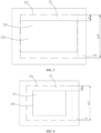
- the first bonding zone 31 has a first outer edge 311, and the second bonding zone 32 has a second outer edge 321. More specifically, as shown in FIG. 4 to FIG. 6 , a distance between an orthographic projection of the second outer edge 321 onto the first surface and the first outer edge 311 is h, and a width of the first bonding zone 31 is W2, where 0.035 ⁇ W2 ⁇ h ⁇ 0.4 ⁇ W2. In a specific embodiment, 0.05 ⁇ W2 ⁇ h ⁇ 0.35 ⁇ W2. For example, h may be 0.2 ⁇ W2, 0.3 ⁇ W2, or the like. That is, the orthographic projection of the second outer edge 321 onto the first surface misaligns with the first outer edge 311. The foregoing misalignment may exist at one of four sides (as shown in FIG. 4 ), at two opposite sides (as shown in FIG. 5 ), or at all four sides (as shown in FIG. 6 ) of the insulation tape 3.
- the areas of the first bonding zone 31 and the second bonding zone 32 are appropriate, so that connection between the insulation tape 3 and the housing 1 and connection between the insulation tape 3 and the electrode assembly 2 are both more reliable, and the energy density of the electrochemical apparatus can be increased.
- Group 1 has a structure shown in FIG. 4 , where the foregoing misalignment exists at one side along a width direction of the insulation tape 3.
- Group 2 has a structure shown in FIG. 5 , where the foregoing misalignment exists at two sides along the width direction of the insulation tape 3.
- Group 3 has a structure shown in FIG. 6 , where the foregoing misalignment exists at peripheral sides of the insulation tape 3.
- a first bonding zone 31 and a second bonding zone 32 of a base group have the same shape and size.
- a quantity of times the test is repeated on the lithium-ion battery at each position is set to 20, and it is considered as qualified if the pass rate is not less than 80% (that is, at least 16 electrochemical apparatuses do not fail when dropped).
- the drop condition is: group 1 dropped at a single side, group 2 dropped at two opposite sides, and group 3 dropped at six sides and four corners.
- a length L1 of an electrode assembly 2 of the selected rectangular lithium-ion battery is 87 mm and a width W1 is 64 mm.
- a length L2 of the first bonding zone 31 is 60 mm and a width W2 is 42 mm. Test results are shown in the following table.
- an electrode assembly 2 has a third surface 21 that is bonded to an insulation tape 3, that is, the third surface 21 of the electrode assembly 2 is bonded to a first bonding zone 31 of the insulation tape 3, and the first bonding zone 31 covers an orthographic projection of a second bonding zone 32 onto the third surface 21.
- a length of the third surface 21 of the electrode assembly 2 is L1
- the first bonding zone 31 has a first axis 312
- the third surface 21 has a second axis 211
- the first axis 312 and the second axis 211 are both axes extending along the width direction of the electrochemical apparatus.
- the first bonding zone 31 is symmetric to the first axis 312 and the third surface 21 is symmetric to the second axis 211.
- a distance between an orthographic projection of the first axis 312 onto the third surface 21 and the second axis 211 is D, where D may be specifically 0.
- L and L1 may satisfy D ⁇ 0.1 ⁇ L1.
- D may be 0.05 ⁇ L1, 0.06 ⁇ L1, or the like.
- the first bonding zone 31 of the insulation tape 3 has a third axis 313, the third surface 21 has a fourth axis 212, and the third axis 313 and the fourth axis 212 are both axes extending along the length direction of the electrochemical apparatus.
- the first bonding zone 31 of the insulation tape 3 has a third axis 313
- the third surface 21 has a fourth axis 212
- the third axis 313 and the fourth axis 212 are both axes extending along the length direction of the electrochemical apparatus.
- the first bonding zone 31 is symmetric to the third axis 313 and the third surface 21 is symmetric to the fourth axis 212.
- a distance between an orthographic projection of the third axis 313 onto the third surface 21 and the fourth axis 212 is E, where E may be specifically 0.
- E and W1 may satisfy E ⁇ 0.15 ⁇ W1.
- a distance between D and L1 and a distance between E and W1 can be set as appropriate to the actual situation, as long as reliability of connection between the insulation tape 3 and the electrode assembly 2 can be improved and a risk of breaking them at an edge can be reduced.
- a weight of the electrode assembly 2 at various positions is uneven and the reliability of connection between the insulation tape 3 and the electrode assembly 2 is affected by gravity of the electrode assembly 2. Therefore, when the weight of the electrode assembly 2 is uneven, an impact of the gravity of the electrode assembly 2 on the reliability of connection between the insulation tape 3 and the electrode assembly 2 can be reduced by changing a location of the insulation tape 3 on the third surface 21.
- an orthographic projection of a geometric center of the second bonding zone 32 onto the first surface coincides with a geometric center of the first bonding zone 31.
- a ratio of a distance from the geometric center of the first bonding zone 31 to a first outer edge 311 along a direction to a distance from the geometric center of the first bonding zone 31 to a second outer edge 321 along the same direction is the same as a ratio of a distance from the geometric center of a second bonding zone 32 to the first outer edge 311 along the direction to a distance from the geometric center of the second bonding zone 32 to the second outer edge 321 along the same direction.
- the geometric center of the second bonding zone 32 is located on a same straight line as the geometric center of the first bonding zone 31. Therefore, after the insulation tape 3 is bonded to the housing 1 and the electrode assembly 2, the first bonding zone 31 and the second bonding zone 32 receives relatively even force, which improves a structural strength of the insulation tape 3.
- the orthographic projection of the second bonding zone 32 onto the first surface is located in the middle of the first bonding zone 31. This can further improve evenness of a force transferred from the second bonding zone 32 to the first bonding zone 31 and improve the structural strength of the insulation tape 3 and a strength of bonding between the insulation tape 3 and the electrode assembly 2.
- the electrode assembly 2 has the third surface 21 that is bonded to the insulation tape 3, where a length of the third surface 21 is L1 and a width is W1.
- a length of the first bonding zone 31 of the insulation tape 3 that is used to be bonded to the electrode assembly 2 is L2 and a width is W2, where 0.4 ⁇ L1 ⁇ L2 ⁇ 0.8 ⁇ L1 and 0.4 ⁇ W1 ⁇ W2 ⁇ 0.8 ⁇ W1.
- L2 may be specifically 0.4 ⁇ L1, 0.5 ⁇ L1, 0.7 ⁇ L1, 0.8 ⁇ L1, or the like
- W2 may be specifically 0.4 ⁇ W1, 0.6 ⁇ W1, 0.7 ⁇ W1, 0.8 ⁇ W1, or the like.
- a relationship between L1 and L2 and that between W1 and W2 are not limited to the foregoing relationships, and can be set as appropriate to the actual situation, as long as the reliability of connection between the insulation tape 3 and the electrode assembly 2 can be improved and the electrode assembly 2 can be prevented from being torn out.
- the insulation tape 3 may have an integral structure, and the insulation tape 3 can be formed, in a processing manner such as cutting, to have the first bonding zone 31 and the second bonding zone 32 that have unequal areas.
- the integrally structured insulation tape 3 has advantages of simple structure and high strength.
- the insulation tape 3 may have a separated structure, that is, the insulation tape 3 includes two tapes and both the two tapes are double-sided adhesive tapes, so that one surface of one of the tapes is used to be bonded to one surface of the other tape, and the other surfaces of the tapes are respectively used to be bonded to the housing 1 and the electrode assembly 2.
- the separately structured insulation tape 3 has advantages of simple structure and convenient processing, and can easily implement that the first bonding zone 31 and the second bonding zone 32 of the insulation tape 3 have different bonding forces.
- the insulation tape 3 includes a first adhesive 33, a substrate 35, and a second adhesive 34 that are laminated, the substrate 35 is located between the first adhesive 33 and the second adhesive 34 and is connected to both.
- the first adhesive 33 is used to be bonded to the electrode assembly 2, that is, the first bonding zone 31 is disposed at the first adhesive 33.
- the second adhesive 34 is used to be bonded to the housing 1, that is, the second bonding zone 32 is disposed at the second adhesive 34.
- an area of the first adhesive 33 is larger than an area of the second adhesive 34, and a size of the substrate 35 is equal to a size of the first adhesive 33 whose area is larger.
- the first adhesive 33 may be bonded to the substrate 35, and the second adhesive 34 may also be bonded to the substrate 35.
- the substrate 35 of the insulation tape 3 is capable of playing a role of supporting the first adhesive 33 and the second adhesive 34, thereby improving the structural strength of the insulation tape 3, further reducing a risk of damage to the insulation tape 3 under an action of an external force, and improving reliability of connection between the housing 1 and the electrode assembly 2.
- the separately structured insulation tape 3 has advantages of simple structure and convenient processing, and can easily implement that the first bonding zone 31 and the second bonding zone 32 of the insulation tape 3 have different bonding forces.
- a shape of a first bonding zone 31 and a second bonding zone 32 in an insulation tape 3 is selected from any one of square, rectangle, trapezium, octagon, circle, or oval.
- the electrochemical apparatus in the embodiments of this application can be used in a plurality of fields.
- Devices can use the electrochemical apparatus in the embodiments of this application as long as the devices can use electrochemical apparatuses for power supply.
- the electrochemical apparatus may be used for components such as an electrochemical apparatus and an electronic apparatus of an electric vehicle.
- the electronic apparatus may be a mobile phone, a tablet computer, a desktop computer, a laptop computer, a handheld computer, a notebook computer, an ultra-mobile personal computer (ultra-mobile personal computer, UMPC), a netbook, a cellular phone, a personal digital assistant (personal digital assistant, PDA), an augmented reality (augmented reality, AR) device, a virtual reality (virtual reality, VR) device, an artificial intelligence (artificial intelligence, AI) device, a wearable device, an onboard device, a smart home device and/or a smart city device, an electric tool, an energy storage apparatus, an electric tricycle, an electric vehicle, or the like.
- a specific type of the electronic apparatus is not specially limited in the embodiments of this application.
- the electronic device may include components such as a housing, a screen, a circuit board, and an electrochemical apparatus, where the screen, circuit board, and electrochemical apparatus are all installed inside the housing, and the electrochemical apparatus is the electrochemical apparatus according to any one of the foregoing embodiments.
Landscapes
- Chemical & Material Sciences (AREA)
- Chemical Kinetics & Catalysis (AREA)
- Electrochemistry (AREA)
- General Chemical & Material Sciences (AREA)
- Secondary Cells (AREA)
- Electric Double-Layer Capacitors Or The Like (AREA)
- Cell Separators (AREA)
- Connection Of Batteries Or Terminals (AREA)
Abstract
Description
- This application relates to the field of energy storage technologies, and in particular, to an electrochemical apparatus and an electronic device.
- With the development of electronic devices, batteries for electronic devices are expected to have larger capacities to satisfy battery life requirements of the electronic devices. A battery for electronic devices generally includes a housing and an electrode assembly that is located inside the housing. The housing plays a role of protecting the electrode assembly. The housing and the electrode assembly may be bonded by using an insulation tape. When the electronic device drops, the insulation tape may possibly tear out the electrode assembly, giving rise to a risk of internal short circuit of the electrode assembly. When the insulation tape is not well bonded, a risk of breaking a top cover may arise, which affects safety of the electronic device.
- This application provides an electrochemical apparatus and an electronic device. The electrochemical apparatus is capable of improving reliability of connection between an electrode assembly and a housing, improving drop resistance, and increasing an energy density of the electrochemical apparatus.
- A first aspect of this application provides an electrochemical apparatus. The electrochemical apparatus includes a housing, an electrode assembly, and an insulation tape, where at least part of the electrode assembly is located inside the housing, and the insulation tape is located between the housing and the electrode assembly. The insulation tape includes a first surface that is bonded to the electrode assembly and a second surface that is bonded to the housing, the first surface includes a first bonding zone, and the second surface includes a second bonding zone, where an area A of the first bonding zone and an area B of the second bonding zone satisfy 0.08≤B/A≤0.965. In another possible design, 0.15≤B/A≤0.85.
- In a possible design, the first bonding zone has a first outer edge, and the second bonding zone has a second outer edge, where a distance between an orthographic projection of the second outer edge onto the first surface and the first outer edge is h, and a width of the first surface is W2, where 0.035×W2≤h≤0.4×W2. In another possible design, 0.05×W2≤h≤0.35×W2.
- In a possible design, the electrode assembly has a third surface that is bonded to the insulation tape, and the first bonding zone covers an orthographic projection of the second bonding zone onto the third surface.
- In a possible design, the electrode assembly has a third surface that is bonded to the insulation tape, and a length of the third surface is L1; and along a width direction of the electrochemical apparatus, the first bonding zone has a first axis, the third surface has a second axis, and a distance between an orthographic projection of the first axis onto the third surface and the second axis is D, where D≤0.1×L1.
- In a possible design, a width of the third surface is W1, and along a length direction of the electrochemical apparatus, the first bonding zone has a third axis, the third surface has a fourth axis, and a distance between an orthographic projection of the third axis onto the third surface and the fourth axis is E, where E≤0.1×W1.
- In a possible design, an orthographic projection of a geometric center of the second bonding zone onto the first surface coincides with a geometric center of the first bonding zone. In a possible design, a ratio of a distance from the geometric center of the first bonding zone to the first outer edge along a direction to a distance from the geometric center of the first bonding zone to the second outer edge along the same direction is the same as a ratio of a distance from the geometric center of the second bonding zone to the first outer edge along the direction to a distance from the geometric center of the second bonding zone to the second outer edge along the same direction.
- In a possible design, a length of the first bonding zone is L2 and a width of the first bonding zone is W2, where 0.4×L1≤L2≤0.8×L1 and 0.4×W1≤W2≤0.8×W1.
- In a possible design, the insulation tape includes a first adhesive, a substrate, and a second adhesive that are laminated, the first adhesive is bonded to the electrode assembly, and the second adhesive is bonded to the housing.
- In a possible design, a shape of the first bonding zone and the second bonding zone is selected from any one of square, rectangle, trapezium, octagon, circle, or oval.
- A second aspect of this application provides an electronic device, and the electronic device includes the electrochemical apparatus described above.
- When the housing of the electrochemical apparatus receives an external force (for example, the housing receives an external force during a drop test), the external force can be transferred from the housing to the second bonding zone of the insulation tape, from the second bonding zone to the first bonding zone, and from the first bonding zone to the electrode assembly. Because the area of the first bonding zone is larger than the area of the second bonding zone, a peeling force per unit area between the first bonding zone and the electrode assembly can be reduced, thereby reducing a risk of the electrode assembly being torn out by the insulation tape under the external force, improving reliability of connection between the electrode assembly and the insulation tape, and further improving safety of the electrode assembly. In addition, when the second surface of the insulation tape that is connected to the housing has a smaller area, the insulation tape is smaller and lighter while reliability of connection between the insulation tape and the housing is ensured, thereby helping increase an energy density of the electrochemical apparatus.
- It should be understood that the foregoing general description and the following detailed description are only exemplary and are not intended to limit this application.
-
-
FIG. 1 is a schematic structural diagram of connection between a housing, an electrode assembly, and an insulation tape according to a first embodiment of this application; -
FIG. 2 is a schematic structural diagram of connection between a housing, an electrode assembly, and an insulation tape according to a second embodiment of this application; -
FIG. 3 is a schematic structural diagram of connection between a housing, an electrode assembly, and an insulation tape according to a third embodiment of this application; -
FIG. 4 is schematic structural diagram of a projection of an insulation tape onto a third surface of an electrode assembly according to a fourth embodiment of this application; -
FIG. 5 is schematic structural diagram of a projection of an insulation tape onto a third surface of an electrode assembly according to a fifth embodiment of this application; -
FIG. 6 is schematic structural diagram of a projection of an insulation tape onto a third surface of an electrode assembly according to a sixth embodiment of this application; -
FIG. 7 is a side view of an electrochemical apparatus according to an embodiment of this application; and -
FIG. 8 is a schematic structural diagram of an electrochemical apparatus according to an embodiment of this application. -
- 1. housing;
- 2. electrode assembly;
21. third surface;- 211. second axis;
- 212. fourth axis;
- 3. insulation tape;
- 31. first bonding zone;
- 311. first outer edge;
- 312. first axis;
- 313. third axis;
- 32. second bonding zone;
321. second outer edge; - 33. first adhesive;
- 34. second adhesive; and
- 35. substrate.
- 31. first bonding zone;
- The accompanying drawings herein are incorporated into this specification and form a part of this specification, illustrate the embodiments conforming to this application, and are intended to explain the principles of this application together with this specification.
- To help better understand the technical solutions of this application, the following describes the embodiments of this application in detail with reference to the accompanying drawings.
- Apparently, the described embodiments are merely some rather than all of the embodiments of this application. All other embodiments obtained based on the embodiments of this application shall fall within the protection scope of this application.
- The terms used in the embodiments of this application are merely intended to describe specific embodiments, but not intended to limit this application. The terms "a/an", "the" and "this" of singular forms used in the embodiments and the appended claims of this application are also intended to include plural forms, unless otherwise specified in the context clearly.
- It should be understood that in this specification, the term "and/or" is merely an association relationship that describes associated objects, indicating that three relationships may exist. For example, A and/or B may indicate three cases: only A, both A and B, and only B. In addition, the character "/" in this specification generally indicates that associated objects are in an "or" relationship.
- It should be noted that the directional terms such as "upper", "lower", "left", and "right" described in the embodiments of this application are described as seen from the angles shown in the accompanying drawings, and should not be understood as limitations to the embodiments of this application. In addition, in the context, it should be further understood that when an element is referred to as being "above" or "under" another element, the element can not only be directly connected "above" or "under" the another element, but also be indirectly connected "above" or "under" the another element through an intermediate element.
- An embodiment of this application provides an electrochemical apparatus. As shown in
FIG. 1 to FIG. 3 , the electrochemical apparatus includes a housing 1 and anelectrode assembly 2. The housing 1 has an accommodation cavity, and at least part of theelectrode assembly 2 is located inside the accommodation cavity. The housing 1 is configured to protect theelectrode assembly 2. Theelectrode assembly 2 may include a first electrode plate, a second electrode plate, and a separator. One of the first electrode plate and the second electrode plate is a positive electrode plate, and the other is a negative electrode plate. The separator is configured to separate the first electrode plate from the second electrode plate. The separator is supported by thermoplastic resin, such as polyethylene or polypropylene. The separator is configured to insulate the first electrode plate and the second electrode plate. - When the electrochemical apparatus is in a drop test, risks such as breaking of a top cover and peeling of aluminum foil of the
electrode assembly 2 are prone to arise, thereby causing short circuit in theelectrode assembly 2 and causing damage to the electrochemical apparatus. To resolve this technical issue, as shown inFIG. 1 to FIG. 3 , the electrochemical apparatus further includes aninsulation tape 3. Theinsulation tape 3 is located between the housing 1 and theelectrode assembly 2. Theinsulation tape 3 includes a first surface that is bonded to theelectrode assembly 2 and a second surface that is bonded to the housing 1, the first surface includes afirst bonding zone 31, and the second surface includes asecond bonding zone 32. Theelectrode assembly 2 is bonded to the housing 1 by using theinsulation tape 3, which prevents theelectrode assembly 2 from moving inside an accommodation cavity of the housing 1 when the electrochemical apparatus is working. Theinsulation tape 3 is further capable of preventing short circuit between theelectrode assembly 2 and the housing 1, so that the electrochemical apparatus can function properly. A bonding strength of theinsulation tape 3 is related to factors such as quality and size of the electrochemical apparatus. Generally, the bonding strength of theinsulation tape 3 ranges from 2 MPa to 20 MPa. In addition, during a drop test, there is further a risk of the aluminum foil of theelectrode assembly 2 being torn out by theinsulation tape 3 under an action of an external force. - In this embodiment, an area of the
first bonding zone 31 is larger than an area of thesecond bonding zone 32, that is, an area of a surface where theinsulation tape 3 is bonded to the housing 1 is smaller than an area of a surface where theinsulation tape 3 is bonded to theelectrode assembly 2. - When the housing 1 of the electrochemical apparatus receives an external force (for example, the housing 1 receives an external force during a drop test), the external force can be transferred from the housing 1 to the
second bonding zone 32 of theinsulation tape 3, from thesecond bonding zone 32 to thefirst bonding zone 31, and from thefirst bonding zone 31 to theelectrode assembly 2. Because the area of thefirst bonding zone 31 is larger than the area of thesecond bonding zone 32, a peeling force per unit area between thefirst bonding zone 31 and theelectrode assembly 2 can be reduced, thereby reducing a risk of the aluminum foil of theelectrode assembly 2 being torn out by theinsulation tape 3, improving reliability of connection between theelectrode assembly 2 and theinsulation tape 3, and further improving safety of theelectrode assembly 2. In addition, when thesecond bonding zone 32 of theinsulation tape 3 that is connected to the housing 1 has a smaller area, theinsulation tape 3 is smaller and lighter while reliability of connection between theinsulation tape 3 and the housing 1 is ensured, thereby helping increase an energy density of the electrochemical apparatus. - Specifically, the area A of the
first bonding zone 31 and the area B of thesecond bonding zone 32 satisfy 0.08≤B/A≤0.965. In a specific embodiment, 0.1≤B/A≤0.6. For example, B/A may be specifically 0.1, 0.3, 0.4, 0.6, 0.8, 0.9, or the like. - In this embodiment, when B/A is excessively large (for example, greater than 0.965), it indicates that the area A of the
first bonding zone 31 is close to the area B of thesecond bonding zone 32. As a result, a peeling force per unit area between an edge of thefirst bonding zone 31 and theelectrode assembly 2 cannot be effectively reduced, thereby increasing the risk of the aluminum foil of theelectrode assembly 2 being torn out by theinsulation tape 3, and reducing safety of theelectrode assembly 2. In addition, theinsulation tape 3 is made excessively heavy and excessively large, and the energy density of the electrochemical apparatus is decreased. When B/A is excessively small (for example, less than 0.08), the area B of thesecond bonding zone 32 is excessively small, which results in a larger peeling force per unit area between theinsulation tape 3 and the housing 1, and reduces the reliability of connection. - More specifically, as shown in
FIG. 1 to FIG. 6 , thefirst bonding zone 31 has a firstouter edge 311, and thesecond bonding zone 32 has a secondouter edge 321. More specifically, as shown inFIG. 4 to FIG. 6 , a distance between an orthographic projection of the secondouter edge 321 onto the first surface and the firstouter edge 311 is h, and a width of thefirst bonding zone 31 is W2, where 0.035×W2≤h≤0.4×W2. In a specific embodiment, 0.05×W2≤h≤0.35×W2. For example, h may be 0.2×W2, 0.3×W2, or the like. That is, the orthographic projection of the secondouter edge 321 onto the first surface misaligns with the firstouter edge 311. The foregoing misalignment may exist at one of four sides (as shown inFIG. 4 ), at two opposite sides (as shown inFIG. 5 ), or at all four sides (as shown inFIG. 6 ) of theinsulation tape 3. - In this embodiment, when h is excessively large, it indicates that a difference between the area of the
second bonding zone 32 and the area of thefirst bonding zone 31 is excessively large, that is, an area of a bonding surface between theinsulation tape 3 and the housing 1 is excessively small, which causes an excessively large peeling force per unit area between theinsulation tape 3 and the housing 1, thereby causing excessively low reliability of connection between theinsulation tape 3 and the housing 1. When h is excessively small, it indicates that the difference between the area of thesecond bonding zone 32 and the area of thefirst bonding zone 31 is excessively small, that is, an area of thefirst bonding zone 31 beyond an edge of thesecond bonding zone 32 is excessively small, which causes an excessively small action area of stress transferred from the edge of thesecond bonding zone 32 to an edge of the first bonding zone, that is, an excessively large peeling force per unit area between the edge of thefirst bonding zone 31 of theinsulation tape 3 and theelectrode assembly 2, thereby causing the aluminum foil of theelectrode assembly 2 to be easily torn out by theinsulation tape 3. In addition, this further causes theinsulation tape 3 to be excessively large and decreases the energy density of the electrochemical apparatus. Therefore, when 0.035×W2≤h≤0.4×W2, the areas of thefirst bonding zone 31 and thesecond bonding zone 32 are appropriate, so that connection between theinsulation tape 3 and the housing 1 and connection between theinsulation tape 3 and theelectrode assembly 2 are both more reliable, and the energy density of the electrochemical apparatus can be increased. - A drop test was performed by using a lithium-ion battery whose maximum projection surface is a rectangle to compare drop pass rates. Group 1 has a structure shown in
FIG. 4 , where the foregoing misalignment exists at one side along a width direction of theinsulation tape 3.Group 2 has a structure shown inFIG. 5 , where the foregoing misalignment exists at two sides along the width direction of theinsulation tape 3.Group 3 has a structure shown inFIG. 6 , where the foregoing misalignment exists at peripheral sides of theinsulation tape 3. Afirst bonding zone 31 and asecond bonding zone 32 of a base group have the same shape and size. A quantity of times the test is repeated on the lithium-ion battery at each position is set to 20, and it is considered as qualified if the pass rate is not less than 80% (that is, at least 16 electrochemical apparatuses do not fail when dropped). The drop condition is: group 1 dropped at a single side,group 2 dropped at two opposite sides, andgroup 3 dropped at six sides and four corners. A length L1 of anelectrode assembly 2 of the selected rectangular lithium-ion battery is 87 mm and a width W1 is 64 mm. A length L2 of thefirst bonding zone 31 is 60 mm and a width W2 is 42 mm. Test results are shown in the following table.Group h (mm) B/A Quantity of failed electrochemical apparatuses Pass rate (%) 1 0.035×42 0.965 3 85 0.05×42 0.95 2 90 0.1×42 0.90 1 95 0.15×42 0.85 0 100 0.2×42 0.80 0 100 0.3×42 0.70 1 95 0.35×42 0.65 2 90 0.4×42 0.60 3 85 2 0.035×42 0.93 3 85 0.05×42 0.90 1 95 0.1×42 0.80 1 95 0.15×42 0.70 0 100 0.2×42 0.60 0 100 0.3×42 0.40 1 95 0.35×42 0.30 2 90 0.4×42 0.20 3 85 3 0.035×42 0.884 3 85 0.05×42 0.837 1 95 0.1×42 0.688 0 100 0.15×42 0.553 0 100 0.2×42 0.432 0 100 0.3×42 0.232 0 100 0.35×42 0.153 2 90 0.4×42 0.088 4 80 Base 0 1 5 75 - It can be learnt from the test results in the foregoing table that after the
insulation tape 3 of this application is provided such that the area A of the first bonding zone and the area B of the second bonding zone satisfy 0.08≤B/A≤0.965, all the electrochemical apparatuses have relatively high pass rates in the drop test, and have higher pass rates (≥90%) when 0.05×W2≤h≤0.35W2. - In a specific embodiment, as shown in
FIG. 4 to FIG. 6 , anelectrode assembly 2 has athird surface 21 that is bonded to aninsulation tape 3, that is, thethird surface 21 of theelectrode assembly 2 is bonded to afirst bonding zone 31 of theinsulation tape 3, and thefirst bonding zone 31 covers an orthographic projection of asecond bonding zone 32 onto thethird surface 21. - In this embodiment, when the
first bonding zone 31 covers the orthographic projection of thesecond bonding zone 32 onto thethird surface 21, an external force transferred from thesecond bonding zone 32 can be fully transferred to thefirst bonding zone 31 via theinsulation tape 3 and thereby transferred to thethird surface 21 of theelectrode assembly 2. This reduces a risk of breaking of theinsulation tape 3 under an action of the external force and improves a structural strength and service life of theinsulation tape 3, thereby improving reliability of connection between the housing 1 and theelectrode assembly 2. - Specifically, as shown in
FIG. 7 , a length of thethird surface 21 of theelectrode assembly 2 is L1, and along a width direction of the electrochemical apparatus, thefirst bonding zone 31 has afirst axis 312, thethird surface 21 has asecond axis 211, and thefirst axis 312 and thesecond axis 211 are both axes extending along the width direction of the electrochemical apparatus. In an embodiment shown inFIG. 7 , along a length direction of the electrochemical apparatus, thefirst bonding zone 31 is symmetric to thefirst axis 312 and thethird surface 21 is symmetric to thesecond axis 211. A distance between an orthographic projection of thefirst axis 312 onto thethird surface 21 and thesecond axis 211 is D, where D may be specifically 0. Alternatively, based on an actual situation, L and L1 may satisfy D≤0.1×L1. For example, D may be 0.05×L1, 0.06×L1, or the like. In addition, as shown inFIG. 7 , along a length direction of the electrochemical apparatus, thefirst bonding zone 31 of theinsulation tape 3 has a third axis 313, thethird surface 21 has a fourth axis 212, and the third axis 313 and the fourth axis 212 are both axes extending along the length direction of the electrochemical apparatus. In the embodiment shown inFIG. 7 , along the width direction of the electrochemical apparatus, thefirst bonding zone 31 is symmetric to the third axis 313 and thethird surface 21 is symmetric to the fourth axis 212. In this embodiment, a distance between an orthographic projection of the third axis 313 onto thethird surface 21 and the fourth axis 212 is E, where E may be specifically 0. Alternatively, based on an actual situation, E and W1 may satisfy E≤0.15×W1. - A distance between D and L1 and a distance between E and W1 can be set as appropriate to the actual situation, as long as reliability of connection between the
insulation tape 3 and theelectrode assembly 2 can be improved and a risk of breaking them at an edge can be reduced. - In this embodiment, a weight of the
electrode assembly 2 at various positions is uneven and the reliability of connection between theinsulation tape 3 and theelectrode assembly 2 is affected by gravity of theelectrode assembly 2. Therefore, when the weight of theelectrode assembly 2 is uneven, an impact of the gravity of theelectrode assembly 2 on the reliability of connection between theinsulation tape 3 and theelectrode assembly 2 can be reduced by changing a location of theinsulation tape 3 on thethird surface 21. - In a possible design, as shown in
FIG. 4 to FIG. 7 , an orthographic projection of a geometric center of thesecond bonding zone 32 onto the first surface coincides with a geometric center of thefirst bonding zone 31. In another possible design, a ratio of a distance from the geometric center of thefirst bonding zone 31 to a firstouter edge 311 along a direction to a distance from the geometric center of thefirst bonding zone 31 to a secondouter edge 321 along the same direction is the same as a ratio of a distance from the geometric center of asecond bonding zone 32 to the firstouter edge 311 along the direction to a distance from the geometric center of thesecond bonding zone 32 to the secondouter edge 321 along the same direction. - In this embodiment, because the orthographic projection of the geometric center of the
second bonding zone 32 onto the first surface coincides with the geometric center of thefirst bonding zone 31, the geometric center of thesecond bonding zone 32 is located on a same straight line as the geometric center of thefirst bonding zone 31. Therefore, after theinsulation tape 3 is bonded to the housing 1 and theelectrode assembly 2, thefirst bonding zone 31 and thesecond bonding zone 32 receives relatively even force, which improves a structural strength of theinsulation tape 3. In addition, because the ratio of the distance from the geometric center of thefirst bonding zone 31 to the firstouter edge 311 along a direction to the distance from the geometric center of thefirst bonding zone 31 to a secondouter edge 321 along the same direction is the same as the ratio of the distance from the geometric center of thesecond bonding zone 32 to the firstouter edge 311 along the direction to the distance from the geometric center of thesecond bonding zone 32 to the secondouter edge 321 along the same direction, the orthographic projection of thesecond bonding zone 32 onto the first surface is located in the middle of thefirst bonding zone 31. This can further improve evenness of a force transferred from thesecond bonding zone 32 to thefirst bonding zone 31 and improve the structural strength of theinsulation tape 3 and a strength of bonding between theinsulation tape 3 and theelectrode assembly 2. - In the foregoing embodiments, as shown in
FIG. 7 , theelectrode assembly 2 has thethird surface 21 that is bonded to theinsulation tape 3, where a length of thethird surface 21 is L1 and a width is W1. A length of thefirst bonding zone 31 of theinsulation tape 3 that is used to be bonded to theelectrode assembly 2 is L2 and a width is W2, where 0.4×L1≤L2≤0.8×L1 and 0.4×W1≤W2≤0.8×W1. For example, L2 may be specifically 0.4×L1, 0.5×L1, 0.7×L1, 0.8×L1, or the like, and W2 may be specifically 0.4×W1, 0.6×W1, 0.7×W1, 0.8×W1, or the like. - A relationship between L1 and L2 and that between W1 and W2 are not limited to the foregoing relationships, and can be set as appropriate to the actual situation, as long as the reliability of connection between the
insulation tape 3 and theelectrode assembly 2 can be improved and theelectrode assembly 2 can be prevented from being torn out. - In a first specific embodiment, as shown in
FIG. 1 , theinsulation tape 3 may have an integral structure, and theinsulation tape 3 can be formed, in a processing manner such as cutting, to have thefirst bonding zone 31 and thesecond bonding zone 32 that have unequal areas. In this embodiment, the integrally structuredinsulation tape 3 has advantages of simple structure and high strength. - In a second specific embodiment, as shown in
FIG. 2 , theinsulation tape 3 may have a separated structure, that is, theinsulation tape 3 includes two tapes and both the two tapes are double-sided adhesive tapes, so that one surface of one of the tapes is used to be bonded to one surface of the other tape, and the other surfaces of the tapes are respectively used to be bonded to the housing 1 and theelectrode assembly 2. In this embodiment, the separately structuredinsulation tape 3 has advantages of simple structure and convenient processing, and can easily implement that thefirst bonding zone 31 and thesecond bonding zone 32 of theinsulation tape 3 have different bonding forces. - In a third specific embodiment, as shown in
FIG. 3 , theinsulation tape 3 includes afirst adhesive 33, asubstrate 35, and a second adhesive 34 that are laminated, thesubstrate 35 is located between thefirst adhesive 33 and thesecond adhesive 34 and is connected to both. Thefirst adhesive 33 is used to be bonded to theelectrode assembly 2, that is, thefirst bonding zone 31 is disposed at thefirst adhesive 33. Thesecond adhesive 34 is used to be bonded to the housing 1, that is, thesecond bonding zone 32 is disposed at thesecond adhesive 34. - As shown in
FIG. 3 , an area of thefirst adhesive 33 is larger than an area of thesecond adhesive 34, and a size of thesubstrate 35 is equal to a size of the first adhesive 33 whose area is larger. The first adhesive 33 may be bonded to thesubstrate 35, and the second adhesive 34 may also be bonded to thesubstrate 35. - In this embodiment, the
substrate 35 of theinsulation tape 3 is capable of playing a role of supporting thefirst adhesive 33 and thesecond adhesive 34, thereby improving the structural strength of theinsulation tape 3, further reducing a risk of damage to theinsulation tape 3 under an action of an external force, and improving reliability of connection between the housing 1 and theelectrode assembly 2. In addition, the separately structuredinsulation tape 3 has advantages of simple structure and convenient processing, and can easily implement that thefirst bonding zone 31 and thesecond bonding zone 32 of theinsulation tape 3 have different bonding forces. - In the foregoing embodiments, as shown in
FIG. 8 , a shape of afirst bonding zone 31 and asecond bonding zone 32 in aninsulation tape 3 is selected from any one of square, rectangle, trapezium, octagon, circle, or oval. - The electrochemical apparatus in the embodiments of this application can be used in a plurality of fields. Devices can use the electrochemical apparatus in the embodiments of this application as long as the devices can use electrochemical apparatuses for power supply. For example, the electrochemical apparatus may be used for components such as an electrochemical apparatus and an electronic apparatus of an electric vehicle. The electronic apparatus may be a mobile phone, a tablet computer, a desktop computer, a laptop computer, a handheld computer, a notebook computer, an ultra-mobile personal computer (ultra-mobile personal computer, UMPC), a netbook, a cellular phone, a personal digital assistant (personal digital assistant, PDA), an augmented reality (augmented reality, AR) device, a virtual reality (virtual reality, VR) device, an artificial intelligence (artificial intelligence, AI) device, a wearable device, an onboard device, a smart home device and/or a smart city device, an electric tool, an energy storage apparatus, an electric tricycle, an electric vehicle, or the like. A specific type of the electronic apparatus is not specially limited in the embodiments of this application.
- Specifically, the electronic device may include components such as a housing, a screen, a circuit board, and an electrochemical apparatus, where the screen, circuit board, and electrochemical apparatus are all installed inside the housing, and the electrochemical apparatus is the electrochemical apparatus according to any one of the foregoing embodiments.
- The foregoing descriptions are merely preferred embodiments of this application, but are not intended to limit this application. Persons skilled in the art understand that this application may have various modifications and variations. Any modification, equivalent replacement, and improvement made without departing from the spirit and principle of this application shall fall within the protection scope of this application.
Claims (10)
- An electrochemical apparatus, characterized by comprising:a housing;an electrode assembly, wherein at least part of the electrode assembly is located inside the housing; andan insulation tape, wherein the insulation tape is located between the housing and the electrode assembly, the insulation tape comprises a first surface that is bonded to the electrode assembly and a second surface that is bonded to the housing, the first surface comprises a first bonding zone, and the second surface comprises a second bonding zone;wherein an area A of the first bonding zone and an area B of the second bonding zone satisfy 0.08≤B/A≤0.965.
- The electrochemical apparatus according to claim 1, characterized in that the first bonding zone has a first outer edge, and the second bonding zone has a second outer edge, whereina distance between an orthographic projection of the second outer edge onto the first surface and the first outer edge is h, and a width of the first surface is W2,wherein 0.035×W2≤h≤0.4×W2.
- The electrochemical apparatus according to claim 2, characterized in that at least one of the following conditions is satisfied:(a) 0.15≤B/A≤0.85; or(b) 0.05×W2≤h≤0.35×W2.
- The electrochemical apparatus according to claim 2, characterized in that the electrode assembly has a third surface that is bonded to the insulation tape, and the first bonding zone covers an orthographic projection of the second bonding zone onto the third surface.
- The electrochemical apparatus according to claim 1, characterized in that the electrode assembly has a third surface that is bonded to the insulation tape, and a length of the third surface is L1; and
along a width direction of the electrochemical apparatus, the first bonding zone has a first axis, the third surface has a second axis, and a distance between an orthographic projection of the first axis onto the third surface and the second axis is D, wherein D≤0.1×L1. - The electrochemical apparatus according to claim 1, characterized in that the electrode assembly has a third surface that is bonded to the insulation tape, and a width of the third surface is W1; and
along a length direction of the electrochemical apparatus, the first bonding zone has a third axis, the third surface has a fourth axis, and a distance between an orthographic projection of the third axis onto the third surface and the fourth axis is E, wherein E≤0.1×W1. - The electrochemical apparatus according to claim 2, characterized in that an orthographic projection of a geometric center of the second bonding zone onto the first surface coincides with a geometric center of the first bonding zone.
- The electrochemical apparatus according to claim 1, characterized in that the insulation tape comprises a first adhesive, a substrate, and a second adhesive that are laminated, the first adhesive is bonded to the electrode assembly, and the second adhesive is bonded to the housing.
- The electrochemical apparatus according to claim 1, characterized in that a shape of the first bonding zone and the second bonding zone is selected from any one of square, rectangle, trapezium, octagon, circle, or oval.
- An electronic device, characterized in that the electronic device comprises the electrochemical apparatus according to any one of claims 1 to 9.
Applications Claiming Priority (1)
| Application Number | Priority Date | Filing Date | Title |
|---|---|---|---|
| PCT/CN2021/074459 WO2022160270A1 (en) | 2021-01-29 | 2021-01-29 | Electrochemical apparatus and electronic device |
Publications (2)
| Publication Number | Publication Date |
|---|---|
| EP4207437A1 true EP4207437A1 (en) | 2023-07-05 |
| EP4207437A4 EP4207437A4 (en) | 2024-11-27 |
Family
ID=79289365
Family Applications (1)
| Application Number | Title | Priority Date | Filing Date |
|---|---|---|---|
| EP21921875.7A Pending EP4207437A4 (en) | 2021-01-29 | 2021-01-29 | ELECTROCHEMICAL APPARATUS AND ELECTRONIC DEVICE |
Country Status (5)
| Country | Link |
|---|---|
| US (1) | US20230238653A1 (en) |
| EP (1) | EP4207437A4 (en) |
| JP (1) | JP7467507B2 (en) |
| CN (2) | CN113939952B (en) |
| WO (1) | WO2022160270A1 (en) |
Families Citing this family (5)
| Publication number | Priority date | Publication date | Assignee | Title |
|---|---|---|---|---|
| CN119013816A (en) * | 2023-12-01 | 2024-11-22 | 宁德新能源科技有限公司 | Electrochemical device and electric equipment |
| WO2025245711A1 (en) * | 2024-05-29 | 2025-12-04 | 宁德新能源科技有限公司 | Electrochemical apparatus and electric device |
| WO2026023696A1 (en) * | 2024-07-26 | 2026-01-29 | Toppanホールディングス株式会社 | Support film for semi-solid battery current collector |
| WO2026023695A1 (en) * | 2024-07-26 | 2026-01-29 | Toppanホールディングス株式会社 | Support film for current collector for semi-solid battery |
| WO2026065452A1 (en) * | 2024-09-30 | 2026-04-02 | 宁德新能源科技有限公司 | Secondary battery and electrical device |
Family Cites Families (16)
| Publication number | Priority date | Publication date | Assignee | Title |
|---|---|---|---|---|
| JP4777320B2 (en) * | 2007-09-25 | 2011-09-21 | 富士通株式会社 | Electronics |
| JP5055198B2 (en) * | 2008-04-30 | 2012-10-24 | 日立ビークルエナジー株式会社 | Battery module |
| WO2012046911A1 (en) * | 2010-10-04 | 2012-04-12 | 주식회사 엘지화학 | Seal tape and secondary battery using same |
| JP2013025999A (en) * | 2011-07-20 | 2013-02-04 | Hitachi Maxell Energy Ltd | Nonaqueous secondary battery |
| JP2013114797A (en) | 2011-11-25 | 2013-06-10 | Sanyo Electric Co Ltd | Manufacturing method of nonaqueous electrolyte battery |
| KR102154327B1 (en) * | 2013-12-16 | 2020-09-09 | 삼성에스디아이 주식회사 | Jelly roll tape for rechargeable battery and rechargeable battery having the same |
| CN105449255B (en) | 2014-08-05 | 2019-01-08 | 东莞新能源科技有限公司 | Electrochemical energy storage device |
| CN105742712A (en) * | 2014-12-08 | 2016-07-06 | 东莞新能源科技有限公司 | Electrochemical energy storage device |
| US20170199217A1 (en) * | 2016-01-13 | 2017-07-13 | Seiko Epson Corporation | Electronic device, method for manufacturing electronic device, and physical-quantity sensor |
| WO2017158703A1 (en) * | 2016-03-14 | 2017-09-21 | 株式会社村田製作所 | Power storage device |
| CN205723715U (en) * | 2016-07-06 | 2016-11-23 | 宁德新能源科技有限公司 | Flexible packing lithium ion battery |
| CN109423227B (en) | 2017-07-19 | 2023-11-14 | 东莞新能源科技有限公司 | Single-sided adhesive material and secondary battery |
| CN210156440U (en) * | 2018-01-05 | 2020-03-17 | 宁德新能源科技有限公司 | Battery |
| CN110350236B (en) * | 2018-04-08 | 2021-07-30 | 宁德时代新能源科技股份有限公司 | Electrochemical energy storage device |
| CN110504400B (en) * | 2019-09-26 | 2023-04-07 | 闻泰通讯股份有限公司 | battery fixing structure |
| CN211654922U (en) * | 2020-04-30 | 2020-10-09 | 北京小米移动软件有限公司 | Soft package power supply device and electronic equipment with same |
-
2021
- 2021-01-29 CN CN202180003680.0A patent/CN113939952B/en active Active
- 2021-01-29 WO PCT/CN2021/074459 patent/WO2022160270A1/en not_active Ceased
- 2021-01-29 JP JP2021571618A patent/JP7467507B2/en active Active
- 2021-01-29 EP EP21921875.7A patent/EP4207437A4/en active Pending
- 2021-01-29 CN CN202410924864.6A patent/CN118888941A/en active Pending
-
2023
- 2023-03-30 US US18/128,424 patent/US20230238653A1/en active Pending
Also Published As
| Publication number | Publication date |
|---|---|
| CN113939952B (en) | 2024-07-30 |
| JP7467507B2 (en) | 2024-04-15 |
| CN118888941A (en) | 2024-11-01 |
| US20230238653A1 (en) | 2023-07-27 |
| WO2022160270A1 (en) | 2022-08-04 |
| EP4207437A4 (en) | 2024-11-27 |
| CN113939952A (en) | 2022-01-14 |
| JP2024079837A (en) | 2024-06-11 |
| JP2023514880A (en) | 2023-04-12 |
Similar Documents
| Publication | Publication Date | Title |
|---|---|---|
| US20230238653A1 (en) | Electrochemical apparatus and electronic device | |
| CN114270621B (en) | Electrochemical devices and electronic devices | |
| US20230238565A1 (en) | Electrochemical device and electronic device | |
| KR101984265B1 (en) | Pouch type secondary battery and method of fabricating the same | |
| US12176552B2 (en) | Battery cell having internal protective layer, and electric device | |
| KR20260051473A (en) | Electrodes, battery cells, and electrical devices | |
| US20240347862A1 (en) | Battery cell, battery, and electrical device | |
| CN111261826B (en) | Electrode assembly, battery using same and electric device | |
| WO2022160269A1 (en) | Electrochemical apparatus and electronic device | |
| EP4131557A1 (en) | Electrochemical apparatus and electronic apparatus using electrochemical apparatus | |
| US11545726B2 (en) | Electrode assembly and battery | |
| WO2023185270A1 (en) | Battery pack and electric device | |
| US20200381783A1 (en) | Battery pack with overmolded module | |
| KR20160071108A (en) | Pouch type secondary battery and method of fabricating the same | |
| US20250105453A1 (en) | Electrochemical device and electronic device | |
| US20240322303A1 (en) | Battery | |
| KR102656480B1 (en) | Battery Pack | |
| US20230290994A1 (en) | Battery and electronic device | |
| CN217281003U (en) | Battery components and terminal equipment | |
| EP4462536A1 (en) | Battery and electrical device | |
| JP7860162B2 (en) | Electrochemical equipment and electronic equipment | |
| CN116259856A (en) | secondary battery | |
| CN117941164A (en) | Electrochemical devices and electronic devices | |
| CN224204130U (en) | Pole core, battery cell, battery device and electric equipment | |
| KR101812753B1 (en) | Battery pack |
Legal Events
| Date | Code | Title | Description |
|---|---|---|---|
| STAA | Information on the status of an ep patent application or granted ep patent |
Free format text: STATUS: THE INTERNATIONAL PUBLICATION HAS BEEN MADE |
|
| PUAI | Public reference made under article 153(3) epc to a published international application that has entered the european phase |
Free format text: ORIGINAL CODE: 0009012 |
|
| STAA | Information on the status of an ep patent application or granted ep patent |
Free format text: STATUS: REQUEST FOR EXAMINATION WAS MADE |
|
| 17P | Request for examination filed |
Effective date: 20230329 |
|
| AK | Designated contracting states |
Kind code of ref document: A1 Designated state(s): AL AT BE BG CH CY CZ DE DK EE ES FI FR GB GR HR HU IE IS IT LI LT LU LV MC MK MT NL NO PL PT RO RS SE SI SK SM TR |
|
| DAV | Request for validation of the european patent (deleted) | ||
| DAX | Request for extension of the european patent (deleted) | ||
| REG | Reference to a national code |
Ref country code: DE Ref legal event code: R079 Free format text: PREVIOUS MAIN CLASS: H01M0050100000 Ipc: H01M0050471000 |
|
| A4 | Supplementary search report drawn up and despatched |
Effective date: 20241025 |
|
| RIC1 | Information provided on ipc code assigned before grant |
Ipc: H01M 50/489 20210101ALI20241021BHEP Ipc: H01M 50/486 20210101ALI20241021BHEP Ipc: H01M 50/477 20210101ALI20241021BHEP Ipc: H01M 50/474 20210101ALI20241021BHEP Ipc: H01M 50/471 20210101AFI20241021BHEP |