EP4207428A1 - Battery - Google Patents
Battery Download PDFInfo
- Publication number
- EP4207428A1 EP4207428A1 EP21923859.9A EP21923859A EP4207428A1 EP 4207428 A1 EP4207428 A1 EP 4207428A1 EP 21923859 A EP21923859 A EP 21923859A EP 4207428 A1 EP4207428 A1 EP 4207428A1
- Authority
- EP
- European Patent Office
- Prior art keywords
- distance
- zone
- layer
- active material
- material layer
- Prior art date
- Legal status (The legal status is an assumption and is not a legal conclusion. Google has not performed a legal analysis and makes no representation as to the accuracy of the status listed.)
- Pending
Links
- 239000007774 positive electrode material Substances 0.000 claims abstract description 43
- 239000007773 negative electrode material Substances 0.000 claims abstract description 33
- 230000007423 decrease Effects 0.000 claims abstract description 17
- 239000000853 adhesive Substances 0.000 claims description 6
- 230000001070 adhesive effect Effects 0.000 claims description 6
- WHXSMMKQMYFTQS-UHFFFAOYSA-N Lithium Chemical compound [Li] WHXSMMKQMYFTQS-UHFFFAOYSA-N 0.000 abstract description 24
- 229910052744 lithium Inorganic materials 0.000 abstract description 24
- 238000001556 precipitation Methods 0.000 abstract description 16
- 150000002500 ions Chemical class 0.000 abstract description 7
- 230000000903 blocking effect Effects 0.000 abstract description 4
- 230000005012 migration Effects 0.000 abstract description 4
- 238000013508 migration Methods 0.000 abstract description 4
- 239000011149 active material Substances 0.000 description 14
- 238000010586 diagram Methods 0.000 description 8
- -1 nickel and copper Chemical class 0.000 description 8
- HBBGRARXTFLTSG-UHFFFAOYSA-N Lithium ion Chemical compound [Li+] HBBGRARXTFLTSG-UHFFFAOYSA-N 0.000 description 6
- PXHVJJICTQNCMI-UHFFFAOYSA-N Nickel Chemical compound [Ni] PXHVJJICTQNCMI-UHFFFAOYSA-N 0.000 description 6
- 229910001416 lithium ion Inorganic materials 0.000 description 6
- RYGMFSIKBFXOCR-UHFFFAOYSA-N Copper Chemical compound [Cu] RYGMFSIKBFXOCR-UHFFFAOYSA-N 0.000 description 5
- 229910052751 metal Inorganic materials 0.000 description 5
- 239000002184 metal Substances 0.000 description 5
- 239000004020 conductor Substances 0.000 description 4
- 239000011810 insulating material Substances 0.000 description 4
- 239000004698 Polyethylene Substances 0.000 description 3
- 229910045601 alloy Inorganic materials 0.000 description 3
- 239000000956 alloy Substances 0.000 description 3
- 229910052782 aluminium Inorganic materials 0.000 description 3
- XAGFODPZIPBFFR-UHFFFAOYSA-N aluminium Chemical compound [Al] XAGFODPZIPBFFR-UHFFFAOYSA-N 0.000 description 3
- 238000005452 bending Methods 0.000 description 3
- 229910052802 copper Inorganic materials 0.000 description 3
- 239000010949 copper Substances 0.000 description 3
- 150000002739 metals Chemical class 0.000 description 3
- 229920000573 polyethylene Polymers 0.000 description 3
- OKTJSMMVPCPJKN-UHFFFAOYSA-N Carbon Chemical compound [C] OKTJSMMVPCPJKN-UHFFFAOYSA-N 0.000 description 2
- 239000004743 Polypropylene Substances 0.000 description 2
- VYPSYNLAJGMNEJ-UHFFFAOYSA-N Silicium dioxide Chemical compound O=[Si]=O VYPSYNLAJGMNEJ-UHFFFAOYSA-N 0.000 description 2
- TZCXTZWJZNENPQ-UHFFFAOYSA-L barium sulfate Chemical compound [Ba+2].[O-]S([O-])(=O)=O TZCXTZWJZNENPQ-UHFFFAOYSA-L 0.000 description 2
- 239000011230 binding agent Substances 0.000 description 2
- CETPSERCERDGAM-UHFFFAOYSA-N ceric oxide Chemical compound O=[Ce]=O CETPSERCERDGAM-UHFFFAOYSA-N 0.000 description 2
- 229910000422 cerium(IV) oxide Inorganic materials 0.000 description 2
- 239000011889 copper foil Substances 0.000 description 2
- 230000000694 effects Effects 0.000 description 2
- 230000002401 inhibitory effect Effects 0.000 description 2
- 239000010954 inorganic particle Substances 0.000 description 2
- 239000000395 magnesium oxide Substances 0.000 description 2
- CPLXHLVBOLITMK-UHFFFAOYSA-N magnesium oxide Inorganic materials [Mg]=O CPLXHLVBOLITMK-UHFFFAOYSA-N 0.000 description 2
- AXZKOIWUVFPNLO-UHFFFAOYSA-N magnesium;oxygen(2-) Chemical compound [O-2].[Mg+2] AXZKOIWUVFPNLO-UHFFFAOYSA-N 0.000 description 2
- 238000004519 manufacturing process Methods 0.000 description 2
- 238000012986 modification Methods 0.000 description 2
- 230000004048 modification Effects 0.000 description 2
- 229910052759 nickel Inorganic materials 0.000 description 2
- 229910000480 nickel oxide Inorganic materials 0.000 description 2
- TWNQGVIAIRXVLR-UHFFFAOYSA-N oxo(oxoalumanyloxy)alumane Chemical compound O=[Al]O[Al]=O TWNQGVIAIRXVLR-UHFFFAOYSA-N 0.000 description 2
- SIWVEOZUMHYXCS-UHFFFAOYSA-N oxo(oxoyttriooxy)yttrium Chemical compound O=[Y]O[Y]=O SIWVEOZUMHYXCS-UHFFFAOYSA-N 0.000 description 2
- RVTZCBVAJQQJTK-UHFFFAOYSA-N oxygen(2-);zirconium(4+) Chemical compound [O-2].[O-2].[Zr+4] RVTZCBVAJQQJTK-UHFFFAOYSA-N 0.000 description 2
- 229920000058 polyacrylate Polymers 0.000 description 2
- 229920001155 polypropylene Polymers 0.000 description 2
- 229910052814 silicon oxide Inorganic materials 0.000 description 2
- 229910001928 zirconium oxide Inorganic materials 0.000 description 2
- ODINCKMPIJJUCX-UHFFFAOYSA-N Calcium oxide Chemical compound [Ca]=O ODINCKMPIJJUCX-UHFFFAOYSA-N 0.000 description 1
- PWHULOQIROXLJO-UHFFFAOYSA-N Manganese Chemical compound [Mn] PWHULOQIROXLJO-UHFFFAOYSA-N 0.000 description 1
- 229910019142 PO4 Inorganic materials 0.000 description 1
- 239000002033 PVDF binder Substances 0.000 description 1
- 239000004952 Polyamide Substances 0.000 description 1
- 239000002202 Polyethylene glycol Substances 0.000 description 1
- 239000004642 Polyimide Substances 0.000 description 1
- 229920002125 Sokalan® Polymers 0.000 description 1
- GWEVSGVZZGPLCZ-UHFFFAOYSA-N Titan oxide Chemical compound O=[Ti]=O GWEVSGVZZGPLCZ-UHFFFAOYSA-N 0.000 description 1
- RTAQQCXQSZGOHL-UHFFFAOYSA-N Titanium Chemical compound [Ti] RTAQQCXQSZGOHL-UHFFFAOYSA-N 0.000 description 1
- 239000004699 Ultra-high molecular weight polyethylene Substances 0.000 description 1
- XLOMVQKBTHCTTD-UHFFFAOYSA-N Zinc monoxide Chemical compound [Zn]=O XLOMVQKBTHCTTD-UHFFFAOYSA-N 0.000 description 1
- PFYQFCKUASLJLL-UHFFFAOYSA-N [Co].[Ni].[Li] Chemical compound [Co].[Ni].[Li] PFYQFCKUASLJLL-UHFFFAOYSA-N 0.000 description 1
- HFCVPDYCRZVZDF-UHFFFAOYSA-N [Li+].[Co+2].[Ni+2].[O-][Mn]([O-])(=O)=O Chemical compound [Li+].[Co+2].[Ni+2].[O-][Mn]([O-])(=O)=O HFCVPDYCRZVZDF-UHFFFAOYSA-N 0.000 description 1
- YWJVFBOUPMWANA-UHFFFAOYSA-H [Li+].[V+5].[O-]P([O-])([O-])=O.[O-]P([O-])([O-])=O Chemical compound [Li+].[V+5].[O-]P([O-])([O-])=O.[O-]P([O-])([O-])=O YWJVFBOUPMWANA-UHFFFAOYSA-H 0.000 description 1
- DPXJVFZANSGRMM-UHFFFAOYSA-N acetic acid;2,3,4,5,6-pentahydroxyhexanal;sodium Chemical compound [Na].CC(O)=O.OCC(O)C(O)C(O)C(O)C=O DPXJVFZANSGRMM-UHFFFAOYSA-N 0.000 description 1
- WNROFYMDJYEPJX-UHFFFAOYSA-K aluminium hydroxide Chemical compound [OH-].[OH-].[OH-].[Al+3] WNROFYMDJYEPJX-UHFFFAOYSA-K 0.000 description 1
- 239000004760 aramid Substances 0.000 description 1
- 229920003235 aromatic polyamide Polymers 0.000 description 1
- 229910001593 boehmite Inorganic materials 0.000 description 1
- AXCZMVOFGPJBDE-UHFFFAOYSA-L calcium dihydroxide Chemical compound [OH-].[OH-].[Ca+2] AXCZMVOFGPJBDE-UHFFFAOYSA-L 0.000 description 1
- 239000000920 calcium hydroxide Substances 0.000 description 1
- 229910001861 calcium hydroxide Inorganic materials 0.000 description 1
- 239000001768 carboxy methyl cellulose Substances 0.000 description 1
- 229920001577 copolymer Polymers 0.000 description 1
- QHGJSLXSVXVKHZ-UHFFFAOYSA-N dilithium;dioxido(dioxo)manganese Chemical compound [Li+].[Li+].[O-][Mn]([O-])(=O)=O QHGJSLXSVXVKHZ-UHFFFAOYSA-N 0.000 description 1
- 239000003792 electrolyte Substances 0.000 description 1
- 239000011888 foil Substances 0.000 description 1
- 229910021389 graphene Inorganic materials 0.000 description 1
- 229910002804 graphite Inorganic materials 0.000 description 1
- 239000010439 graphite Substances 0.000 description 1
- CJNBYAVZURUTKZ-UHFFFAOYSA-N hafnium(iv) oxide Chemical compound O=[Hf]=O CJNBYAVZURUTKZ-UHFFFAOYSA-N 0.000 description 1
- 229910021385 hard carbon Inorganic materials 0.000 description 1
- 229920001903 high density polyethylene Polymers 0.000 description 1
- 239000004700 high-density polyethylene Substances 0.000 description 1
- FAHBNUUHRFUEAI-UHFFFAOYSA-M hydroxidooxidoaluminium Chemical compound O[Al]=O FAHBNUUHRFUEAI-UHFFFAOYSA-M 0.000 description 1
- 230000008595 infiltration Effects 0.000 description 1
- 238000001764 infiltration Methods 0.000 description 1
- GELKBWJHTRAYNV-UHFFFAOYSA-K lithium iron phosphate Chemical compound [Li+].[Fe+2].[O-]P([O-])([O-])=O GELKBWJHTRAYNV-UHFFFAOYSA-K 0.000 description 1
- DVATZODUVBMYHN-UHFFFAOYSA-K lithium;iron(2+);manganese(2+);phosphate Chemical compound [Li+].[Mn+2].[Fe+2].[O-]P([O-])([O-])=O DVATZODUVBMYHN-UHFFFAOYSA-K 0.000 description 1
- 229920001684 low density polyethylene Polymers 0.000 description 1
- 239000004702 low-density polyethylene Substances 0.000 description 1
- VTHJTEIRLNZDEV-UHFFFAOYSA-L magnesium dihydroxide Chemical compound [OH-].[OH-].[Mg+2] VTHJTEIRLNZDEV-UHFFFAOYSA-L 0.000 description 1
- 239000000347 magnesium hydroxide Substances 0.000 description 1
- 229910001862 magnesium hydroxide Inorganic materials 0.000 description 1
- 229910052748 manganese Inorganic materials 0.000 description 1
- 239000011572 manganese Substances 0.000 description 1
- 239000000463 material Substances 0.000 description 1
- 239000002931 mesocarbon microbead Substances 0.000 description 1
- 238000000034 method Methods 0.000 description 1
- 230000003647 oxidation Effects 0.000 description 1
- 238000007254 oxidation reaction Methods 0.000 description 1
- GNRSAWUEBMWBQH-UHFFFAOYSA-N oxonickel Chemical compound [Ni]=O GNRSAWUEBMWBQH-UHFFFAOYSA-N 0.000 description 1
- 239000010452 phosphate Substances 0.000 description 1
- NBIIXXVUZAFLBC-UHFFFAOYSA-K phosphate Chemical compound [O-]P([O-])([O-])=O NBIIXXVUZAFLBC-UHFFFAOYSA-K 0.000 description 1
- 229920003229 poly(methyl methacrylate) Polymers 0.000 description 1
- 239000004584 polyacrylic acid Substances 0.000 description 1
- 229920002239 polyacrylonitrile Polymers 0.000 description 1
- 229920002647 polyamide Polymers 0.000 description 1
- 229920001223 polyethylene glycol Polymers 0.000 description 1
- 229920001721 polyimide Polymers 0.000 description 1
- 239000004926 polymethyl methacrylate Substances 0.000 description 1
- 229920001343 polytetrafluoroethylene Polymers 0.000 description 1
- 239000004810 polytetrafluoroethylene Substances 0.000 description 1
- 229920001289 polyvinyl ether Polymers 0.000 description 1
- 229920002981 polyvinylidene fluoride Polymers 0.000 description 1
- 239000001267 polyvinylpyrrolidone Substances 0.000 description 1
- 229920000036 polyvinylpyrrolidone Polymers 0.000 description 1
- 235000013855 polyvinylpyrrolidone Nutrition 0.000 description 1
- HBMJWWWQQXIZIP-UHFFFAOYSA-N silicon carbide Chemical compound [Si+]#[C-] HBMJWWWQQXIZIP-UHFFFAOYSA-N 0.000 description 1
- 239000002210 silicon-based material Substances 0.000 description 1
- 235000019812 sodium carboxymethyl cellulose Nutrition 0.000 description 1
- 229920001027 sodium carboxymethylcellulose Polymers 0.000 description 1
- 229910021384 soft carbon Inorganic materials 0.000 description 1
- KKEYFWRCBNTPAC-UHFFFAOYSA-L terephthalate(2-) Chemical compound [O-]C(=O)C1=CC=C(C([O-])=O)C=C1 KKEYFWRCBNTPAC-UHFFFAOYSA-L 0.000 description 1
- XOLBLPGZBRYERU-UHFFFAOYSA-N tin dioxide Chemical compound O=[Sn]=O XOLBLPGZBRYERU-UHFFFAOYSA-N 0.000 description 1
- 239000011366 tin-based material Substances 0.000 description 1
- 229920000785 ultra high molecular weight polyethylene Polymers 0.000 description 1
- 125000005287 vanadyl group Chemical group 0.000 description 1
Images




Classifications
-
- H—ELECTRICITY
- H01—ELECTRIC ELEMENTS
- H01M—PROCESSES OR MEANS, e.g. BATTERIES, FOR THE DIRECT CONVERSION OF CHEMICAL ENERGY INTO ELECTRICAL ENERGY
- H01M4/00—Electrodes
- H01M4/02—Electrodes composed of, or comprising, active material
- H01M4/13—Electrodes for accumulators with non-aqueous electrolyte, e.g. for lithium-accumulators; Processes of manufacture thereof
-
- H—ELECTRICITY
- H01—ELECTRIC ELEMENTS
- H01M—PROCESSES OR MEANS, e.g. BATTERIES, FOR THE DIRECT CONVERSION OF CHEMICAL ENERGY INTO ELECTRICAL ENERGY
- H01M4/00—Electrodes
- H01M4/02—Electrodes composed of, or comprising, active material
- H01M4/36—Selection of substances as active materials, active masses, active liquids
- H01M4/362—Composites
- H01M4/366—Composites as layered products
-
- H—ELECTRICITY
- H01—ELECTRIC ELEMENTS
- H01M—PROCESSES OR MEANS, e.g. BATTERIES, FOR THE DIRECT CONVERSION OF CHEMICAL ENERGY INTO ELECTRICAL ENERGY
- H01M10/00—Secondary cells; Manufacture thereof
- H01M10/04—Construction or manufacture in general
- H01M10/0404—Machines for assembling batteries
-
- H—ELECTRICITY
- H01—ELECTRIC ELEMENTS
- H01M—PROCESSES OR MEANS, e.g. BATTERIES, FOR THE DIRECT CONVERSION OF CHEMICAL ENERGY INTO ELECTRICAL ENERGY
- H01M10/00—Secondary cells; Manufacture thereof
- H01M10/04—Construction or manufacture in general
- H01M10/0436—Small-sized flat cells or batteries for portable equipment
-
- H—ELECTRICITY
- H01—ELECTRIC ELEMENTS
- H01M—PROCESSES OR MEANS, e.g. BATTERIES, FOR THE DIRECT CONVERSION OF CHEMICAL ENERGY INTO ELECTRICAL ENERGY
- H01M10/00—Secondary cells; Manufacture thereof
- H01M10/04—Construction or manufacture in general
- H01M10/0459—Cells or batteries with folded separator between plate-like electrodes
-
- H—ELECTRICITY
- H01—ELECTRIC ELEMENTS
- H01M—PROCESSES OR MEANS, e.g. BATTERIES, FOR THE DIRECT CONVERSION OF CHEMICAL ENERGY INTO ELECTRICAL ENERGY
- H01M10/00—Secondary cells; Manufacture thereof
- H01M10/05—Accumulators with non-aqueous electrolyte
- H01M10/052—Li-accumulators
- H01M10/0525—Rocking-chair batteries, i.e. batteries with lithium insertion or intercalation in both electrodes; Lithium-ion batteries
-
- H—ELECTRICITY
- H01—ELECTRIC ELEMENTS
- H01M—PROCESSES OR MEANS, e.g. BATTERIES, FOR THE DIRECT CONVERSION OF CHEMICAL ENERGY INTO ELECTRICAL ENERGY
- H01M10/00—Secondary cells; Manufacture thereof
- H01M10/05—Accumulators with non-aqueous electrolyte
- H01M10/058—Construction or manufacture
- H01M10/0587—Construction or manufacture of accumulators having only wound construction elements, i.e. wound positive electrodes, wound negative electrodes and wound separators
-
- H—ELECTRICITY
- H01—ELECTRIC ELEMENTS
- H01M—PROCESSES OR MEANS, e.g. BATTERIES, FOR THE DIRECT CONVERSION OF CHEMICAL ENERGY INTO ELECTRICAL ENERGY
- H01M4/00—Electrodes
- H01M4/02—Electrodes composed of, or comprising, active material
- H01M4/62—Selection of inactive substances as ingredients for active masses, e.g. binders, fillers
-
- H—ELECTRICITY
- H01—ELECTRIC ELEMENTS
- H01M—PROCESSES OR MEANS, e.g. BATTERIES, FOR THE DIRECT CONVERSION OF CHEMICAL ENERGY INTO ELECTRICAL ENERGY
- H01M4/00—Electrodes
- H01M4/02—Electrodes composed of, or comprising, active material
- H01M2004/021—Physical characteristics, e.g. porosity, surface area
-
- H—ELECTRICITY
- H01—ELECTRIC ELEMENTS
- H01M—PROCESSES OR MEANS, e.g. BATTERIES, FOR THE DIRECT CONVERSION OF CHEMICAL ENERGY INTO ELECTRICAL ENERGY
- H01M2220/00—Batteries for particular applications
- H01M2220/30—Batteries in portable systems, e.g. mobile phone, laptop
-
- Y—GENERAL TAGGING OF NEW TECHNOLOGICAL DEVELOPMENTS; GENERAL TAGGING OF CROSS-SECTIONAL TECHNOLOGIES SPANNING OVER SEVERAL SECTIONS OF THE IPC; TECHNICAL SUBJECTS COVERED BY FORMER USPC CROSS-REFERENCE ART COLLECTIONS [XRACs] AND DIGESTS
- Y02—TECHNOLOGIES OR APPLICATIONS FOR MITIGATION OR ADAPTATION AGAINST CLIMATE CHANGE
- Y02E—REDUCTION OF GREENHOUSE GAS [GHG] EMISSIONS, RELATED TO ENERGY GENERATION, TRANSMISSION OR DISTRIBUTION
- Y02E60/00—Enabling technologies; Technologies with a potential or indirect contribution to GHG emissions mitigation
- Y02E60/10—Energy storage using batteries
Definitions
- This application relates to a battery.
- Lithium-ion batteries have many advantages such as high energy density, long cycle life, high nominal voltage, low self-discharge rate, small size, and light weight, and therefore, are widely used in the field of consumer electronics.
- a size of an active material layer of a negative electrode plate is generally larger than a size of an active material layer of a positive electrode plate.
- a smaller difference between the sizes of the active material layer of the negative electrode plate and the active material layer of the positive electrode plate is desirable.
- the positive electrode active material layer includes a first portion and a second portion connected to the first portion.
- the second portion includes a first end, and the first portion includes a first surface.
- the first surface is connected to the second portion through a first connection, the first end is an end of the positive electrode active material layer, and a thickness of the second portion in a second direction decreases from the first connection to the first end.
- the second direction is perpendicular to the first direction.
- the negative electrode active material layer includes a third portion and a second end located on one side of the third portion in the first direction, and the third portion includes a second surface having at least a part arranged opposite to the first surface.
- a first layer binds the first end, the second portion, and the first surface; and the first layer covers the first end, the second portion, and a part of the first surface. The first layer impedes ion conduction.
- a length of a part of the first layer bound to the first surface in the first direction is less than 5 mm.
- the negative electrode active material layer further includes a fourth portion connected to the third portion in the first direction, the fourth portion is connected to the second surface through a second connection, and an end of the fourth portion opposite from the second connection is the second end; and a thickness of the fourth portion in the second direction decreases from the second connection to the second end, and in the first direction, the second connection is located between the first connection and the first end.
- the second portion includes a third surface
- the fourth portion includes a fourth surface
- the third surface and the first surface are connected through the first connection
- the fourth surface and the second surface are connected through the second connection
- the third surface and the fourth surface are at least partially arranged opposite to each other, and the first layer is bound to and covers the third surface.
- an orthographic projection of the first end in the second direction falls within an orthographic projection of the fourth portion in the first direction.
- the first surface and the second surface at least partially overlap in the second direction
- the third surface and the fourth surface at least partially overlap in the second direction
- the second surface and the third surface at least partially overlap in the second direction
- a distance from the first surface to the second surface in the second direction is a first distance
- a distance from the third surface to the fourth surface in the second direction is a second distance, where the first distance is different from the second distance
- the first distance is less than the second distance.
- a distance from the third surface to the second surface in the second direction is a third distance, and the third distance is greater than the first distance.
- the third distance is less than the second distance.
- the first end viewed from the second direction, has a first zone and a second zone; wherein a first distance from the first zone to the second end in the first direction is different form a second distance from the second zone to the second end in the first direction.
- the first end viewed from the second direction, has a plurality of protrusions.
- the first layer in the first direction, includes a third end and a fourth end that are arranged opposite from each other, and in the first direction, the third end is located on one side of the first connection, and the fourth end is located on another side of the first connection; and viewed from the second direction, a distance from the first end to the third end in the first direction is a fourth distance, a distance from the first end to the fourth end in the first direction is a fifth distance, and the fourth distance is different from the fifth distance.
- the fourth distance is less than the fifth distance.
- the first surface includes a third zone, a step zone, and a fourth zone that are sequentially connected in the first direction; and in the first direction, the third zone is located on one side of the step zone opposite from the first end; a thickness of the fourth zone in the second direction is less than a thickness of the third zone in the second direction; and a part of the first layer that is bound to the first surface covers the fourth zone.
- a thickness of the first layer in the second direction is greater than a height of the step zone in the second direction.
- a part of the first layer located in the fourth zone includes a fifth surface, the fifth surface is opposite from the fourth zone, and the fifth surface includes a part having a distance to the third zone in the second direction greater than a distance to the second surface in the second direction.
- the first layer is a single-sided adhesive paper or a double-sided adhesive paper.
- the thickness of the second portion in the second direction decreases from the first connection to the first end, the second direction being perpendicular to the first direction, thereby helping to improve energy density of the battery; the first layer blocking migration of ions binds the first end, the second portion, and the first surface; and the first layer covers the first end, the second portion, and the part of the first surface, thereby helping to inhibit lithium ions generated by the positive electrode active material layer from reaching the negative electrode active material layer, and thus helping to inhibit lithium precipitation of the battery. Therefore, the structure of the battery in this application helps to inhibit lithium precipitation while maintaining energy density of the battery.
- Spatial related terms such as “above” may be used herein for ease of description to describe the relationship between one element or feature and another element (a plurality of elements) or feature (a plurality of features) as illustrated in the figure. It should be understood that, in addition to the directions described in the figures, the spatial related terms are intended to include different directions in the use or operation of devices or apparatus. For example, if a device in the figure is turned over, an element described as “on” or “above” another element or feature should be oriented “below” or “under” the another element or feature. Therefore, the example term “above” may include directions of above and below.
- connection may also mean “electrically connected” or the like based on its content understood by those skilled in the art.
- an element, component, zone, layer, and/or portion when an element, component, zone, layer, and/or portion is described as being "between" two elements, components, zones, layers, and/or portions, it may be the only element, component, zone, layer, and/or portion between the two elements, components, zones, layers, and/or portions, or one or more intermediate elements, components, zones, layers, and/or portions may be present.
- first, second, third, or the like may be used herein to describe various elements, components, zones, layers, and/or portions, these elements, components, zones, layers, and/or portions should not be limited by these terms. These terms are used to distinguish one element, component, zone, layer, or portion from another element, component, zone, layer, or portion. Therefore, the first element, component, zone, layer, or portion discussed below may be referred to as the second element, component, zone, layer, or portion without departing from the teachings of the example embodiments.
- a first direction X and a third direction Z are perpendicular to each other and parallel to a main plane of an electrode assembly
- a second direction Y is perpendicular to the main plane of the electrode assembly, that is, a thickness direction of the electrode assembly.
- the main plane of the electrode assembly is a surface (100B in FIG. 1 ) of a flat portion of the electrode assembly.
- the thickness direction of the electrode assembly is a stacking direction of electrode plates in the flat portion of the electrode assembly.
- a battery 100 includes an electrode assembly 100A.
- FIG. 2 is a cross-section of a plane formed by the battery 100 in FIG. 1 in directions X and Y
- the electrode assembly 100A includes a negative electrode plate 10A, a positive electrode plate 30A, and a separator 50 located between the positive electrode plate 10A and the negative electrode plate 30A.
- the separator 50 is an electrical insulating material, and ions can pass through the separator 50.
- a positional relationship between the negative electrode plate 10A and the positive electrode plate 30A is further described below.
- the negative electrode plate 10A, the separator 50, and the positive electrode plate 30A are stacked to form a stack, and then the stack is wound around a central axis O-O of the third direction Z for multiple times to form the electrode assembly 100A.
- the electrode assembly 100A includes a flat portion 100AA, and a plurality of bending end portions 100AB in the X direction, and the plurality of bending end portions 100AB are distributed on opposite sides of a center of the flat portion 100AA of the battery 100 in the X direction, and on the left and right sides in FIG. 2 .
- the positive electrode plate 30A is further described below.
- the positive electrode plate 30A includes a positive electrode active material layer 30 and a positive electrode current collector 30a.
- the positive electrode active material layer 30 is provided on a surface of the positive electrode current collector 30a.
- the positive electrode current collector 30a is conductive and includes a conductive material.
- the conductive material may include at least one or more of conductive metals such as aluminum, copper, and nickel, and alloys thereof.
- the positive electrode current collector 30a may include but is not limited to at least one or more of conductive metal sheets such as aluminum meshes, aluminum foil, copper meshes, copper foil, and nickel foil.
- the positive electrode current collector 30a includes a first face 30aa and a second face 30ab that are disposed back to back with each other.
- the first face 30aa of the positive electrode current collector 30a includes a first zone 30a1 and a second zone 30a2, and the second face 30ab of the positive electrode current collector 30a includes a first zone 30a1 and a second zone 30a2.
- the first zones 30a1 are zones where active materials are provided to form an active material layer
- the second zones 30a2 are zones where no active material layer is formed.
- the first face 30aa may include two second zones 30a2 that are connected to two ends of the first zone 30a1 of the first face 30aa
- the second face 30ab may include two second zones 30a2 that are connected to two ends of the first zone 30a1 of the second face 30ab.
- An area of the first zone 30a1 of the first face 30aa may be less than an area of the first zone 30a1 of the second face 30ab.
- the positive electrode active material layer 30 is provided in the first zone 30a1 of the first face 30aa and the first zone 30a1 of the second face 30ab of the positive electrode current collector 30a.
- the positive electrode active material layer 30, may include at least but is not limited to one or more of lithium cobaltate, lithium nickel cobalt manganate, lithium nickel cobalt aluminate, lithium manganate, lithium nickelate, lithium manganese iron phosphate, lithium vanadium phosphate, lithium vanadyl phosphate, lithium iron phosphate, and lithium-rich manganese-based materials.
- a thickness of the positive electrode current collector 30a may be 3 micrometers to 15 micrometers, and a thickness of the positive electrode active material layer 30 may be 80 micrometers to 300 micrometers.
- a ratio of a thickness of the positive electrode active material layer 30 to a thickness of the positive electrode current collector 30a may be 5 to 30, helping to reduce a proportion of the thickness of the positive electrode current collector 30a to an overall thickness of the battery, thereby helping to increase energy density of the battery.
- the positive electrode active material layer 30 includes a first portion 31 and a second portion 33 connected to the first portion 31 in the first direction X.
- the first portion 31 includes a first surface 310
- the second portion 33 includes a third surface 330 and a first end 331.
- the first surface 310 is connected to the third surface 330 through a first connection 301.
- the first end 331 is an end of the second portion 33 opposite from the first connection 301, and the first end 331 is an end of the positive electrode active material layer 30.
- a thickness of the second portion 33 in the second direction Y progressively decreases from the first connection 301 to the first end 331, the second direction Y being perpendicular to the first direction X.
- the thickness of the second portion 33 in the second direction Y decreases monotonically from the first connection 301 to the first end 331, where the thickness may decrease linearly or decrease curvilinearly.
- the first end 331 is located in the flat portion 100AA.
- the positive electrode active material layer 30 is disposed in the first zone 30a1, and the second zone 30a2 is provided on one side of the first end 331 opposite from the first connection 301 in the first direction X.
- the negative electrode plate 10A is further described below.
- the negative electrode plate 10A includes a negative electrode active material layer 10 and a negative electrode current collector 10a.
- the negative electrode active material layer 10 is provided on a surface of the negative electrode current collector 10a.
- the negative electrode current collector 10a is conductive and includes a conductive material.
- the conductive material may include at least one or more of conductive metals such as nickel and copper, and alloys thereof.
- the negative electrode current collector 10a may include but is not limited to at least one or two of conductive metal sheets such as nickel foil and copper foil.
- the negative electrode current collector 10a includes a first face 10aa and a second face 10ab that are disposed back to back with each other.
- the first face 10aa of the negative electrode current collector 10a includes a first zone 10a1 and a second zone 10a2, and the second face 10ab of the negative electrode current collector 10a includes a first zone 10a1 and a second zone 10a2.
- the first zones 10a1 are zones where active materials are provided to form an active material layer
- the second zones 10a2 are zones where no active material layer is formed.
- the first face 10aa may include two second zones 10a2 that are connected to two ends of the first zone 10a1 of the first face 10aa
- the second face 10ab may include two second zones 10a2 that are connected to two ends of the first zone 10a1 of the second face 10ab.
- An area of the first zone 10a1 of the first face 10aa may be greater than an area of the first zone 10a1 of the second face 10ab.
- the negative electrode active material layer 10 is provided in the first zone 10a1 of the first face 10aa and the first zone 10a1 of the second face 10ab of the negative electrode current collector 10a.
- the negative electrode active material layer 10 may include at least but is not limited to one or more of graphite, soft carbon, hard carbon, graphene, meso-carbon microbeads, silicon-based materials, tin-based materials, lithium titanate, or other metals capable of forming alloys with lithium.
- a thickness of the negative electrode current collector 10a may be 2 micrometers to 13 micrometers, and a thickness of the negative electrode active material layer 10 may be 80 micrometers to 300 micrometers.
- a ratio of a thickness of the negative electrode active material layer 10 to a thickness of the negative electrode current collector 10a may be 5 to 60, helping to reduce a proportion of the thickness of the negative electrode current collector 10a to an overall thickness of the battery, thereby helping to increase energy density of the battery.
- the negative electrode active material layer 10 includes a third portion 11 and a fourth portion 13 connected to the third portion 11 in the first direction X.
- the third portion 11 includes a second surface 110
- the fourth portion 13 includes a fourth surface 130 and a second end 131.
- the second surface 110 is connected to the fourth surface 130 through a second connection 101.
- the second end 131 is an end of the fourth portion 13 opposite from the second connection 101, and the second end 131 is an end of the negative electrode active material layer 10.
- a thickness of the fourth portion 13 in the second direction Y may progressively decrease from the second connection 101 to the second end 131. In some embodiments, a thickness of the fourth portion 13 in the second direction Y decreases monotonically from the second connection 101 to the second end 131, where the thickness may decrease linearly or decrease curvilinearly.
- the second end 131 is located in the flat portion 100AA.
- the negative electrode active material layer 10 is disposed in the first zone 10a1, and the second zone 10a2 is provided on one side of the second end 131 opposite from the second connection 101 in the first direction X.
- the first face 10aa of the negative electrode current collector 10a is disposed toward the second face 30ab of the positive electrode current collector 30a, and the second face 10ab of the negative electrode current collector 10a is disposed toward the first face 30aa of the positive electrode current collector 30a.
- the separator 50 is located between the negative electrode active material layer 10 and the positive electrode active material layer 30.
- the separator 50 includes an electrical insulating material.
- it may include but is not limited to at least one or more of polyethylene, polypropylene, polyethylene glycol terephthalate, polyimide, and aramid.
- polyethylene includes at least one component selected from high-density polyethylene, low-density polyethylene, and ultra-high-molecular-weight polyethylene.
- polyethylene and polypropylene have a good effect on preventing short-circuit, and can improve stability of the lithium-ion battery through the shutdown effect.
- a surface of the separator may further include a porous layer.
- the porous layer is arranged on at least one surface of the separator and includes inorganic particles and a binder.
- the inorganic particles are selected from a combination of one or more of aluminum oxide (Al 2 O 3 ), silicon oxide (SiO 2 ), magnesium oxide (MgO), titanium oxide (TiO 2 ), hafnium oxide (HfO 2 ), stannic oxide (SnO 2 ), cerium dioxide (CeO 2 ), nickel oxide (NiO), zinc oxide (ZnO), calcium oxide (CaO), zirconium oxide (ZrO 2 ), yttrium oxide (Y 2 O 3 ), silicon carbide (SiC), boehmite, aluminum hydroxide, magnesium hydroxide, calcium hydroxide, and barium sulfate.
- the binder may be selected from but is not limited to a combination of one or more of polyvinylidene fluoride, a vinylidene fluoride-hexafluoropropylene copolymer, polyamide, polyacrylonitrile, polyacrylate, polyacrylic acid, polyacrylate, sodium carboxymethyl cellulose, polyvinylpyrrolidone, polyvinyl ether, polymethyl methacrylate, polytetrafluoroethylene, and polyhexafluoropropylene.
- the porous layer can improve heat resistance, oxidation resistance, and electrolyte infiltration performance of the separator, and enhance adhesion between the separator and a positive electrode or negative electrode.
- the separator 50 is a film layer including a plurality of holes. As shown in FIG. 2 , each break in the separator 50 is a hole.
- the separator 50 in the drawings is in contact with neither the negative electrode active material layer 10 nor the positive electrode active material layer 30, but in some embodiments, the separator 50 may be in contact with at least a part of the negative electrode active material layer 10 and the positive electrode active material layer 30.
- the second end 131 serves as an end of the negative electrode active material layer 10 close to an end, that is, part III, of the wound electrode assembly 100A
- the first end 331 serves as an end of the positive electrode active material layer 30 close to an end of the wound electrode assembly 100A.
- the negative electrode active material layer 10 and the positive electrode active material layer 30 are arranged opposite to each other.
- the second surface 110 and the first surface 310 are at least partially arranged opposite to each other. That is, viewed from the second direction Y, the second surface 110 and the first surface 310 at least partially overlap.
- the fourth surface 130 and the third surface 330 may be at least partially arranged opposite to each other. That is, viewed from the second direction Y, the fourth surface 130 and the third surface 330 at least partially overlap.
- the second connection 101 may be located between the first connection 301 and the first end 331.
- the thickness of the fourth portion 13 in the second direction Y progressively decreases from the second connection 101 to the second end 131, and the thickness of the second portion 33 in the second direction Y progressively decreases from the first connection 301 to the first end 331, helping to inhibit lithium precipitation while maintaining energy density of the battery 100.
- the first end 331 may be located between the second connection 101 and the second end 131. That is, viewed from the second direction Y, the fourth surface 130 and the third surface 330 at least partially overlap, thereby further helping to inhibit lithium precipitation of the battery.
- a distance from the first surface 310 to the second surface 110 in the second direction Y is a first distance D1
- a distance from the third surface 330 to the fourth surface 130 in the second direction Y is a second distance D2
- a distance from the third surface 330 to the second surface 110 in the second direction Y is a third distance D3.
- D1 is different from D2, and D1 is different from D3.
- D2 is greater than D1
- D3 is greater than D1
- D3 is different from D2. More specifically, D3 is less than D2.
- the second end 131 and the first end 331 may be arranged in parallel or not.
- the second end 131 may be linear or curved in the third direction Z, and the first end 331 may also be linear or curved.
- the first end 331 has a first zone with a first distance E1 from the first zone to the second end 131 in the first direction X, and the first end 331 may further have a second zone with a second distance E2 from the second zone to the second end 131 in the first direction X.
- E1 and E2 are not equal.
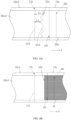
- FIG. 4B is a partial cross-sectional top view of the battery in a plane formed in the directions X and Z. The cross-section shows the positive electrode active material layer 30. In FIG. 4B , a distance from an end of the positive electrode active material layer 30 close to the second end 131 in the first direction X to the second end 131 is greater than a distance from the first end 331 to the second end 131 in the first direction X.
- the first end 331 may have a plurality of protrusions 333.
- the first end 331 may be in but is not limited to a wave or zigzag shape.
- the second end 131 may also have a plurality of protrusions 133.
- the second end 131 may be in but is not limited to a wave or zigzag shape.
- the battery 100 further includes a first layer 60, and the first layer 60 includes an insulating material.
- the first layer 60 is capable of impeding ion conduction, for example, blocking or isolating migration of ions.
- the first layer 60 may be a single-sided adhesive paper or a double-sided adhesive paper.
- the first layer 60 binds the first end 331 and the third surface 330; and the first layer covers the first end 331 and the third surface 330, and inhibits lithium precipitation of the battery by preventing lithium ions generated by the positive electrode active material layer 30 from reaching the opposite negative electrode active material layer 10.
- the first layer 60 may further extend from the third surface 330 to the first surface 310 to bind the first surface 310 and cover a part of the first surface 310, thereby further preventing the lithium ions generated by the positive electrode active material layer 30 from reaching the negative electrode active material layer 10, thus avoiding lithium precipitation.
- a length of a part of the first layer 60 bound to the first surface 310 in the first direction X may be less than or equal to 5 mm, so as to reduce energy density loss while inhibiting lithium precipitation of the battery.
- the first layer 60 may further extend from the first end 331 to the second zone 30a2 to bind the second zone 30a2 and cover at least a part of the second zone 30a2, so as to help ensure that the first layer 60 is still bound to the first end 331 when an edge of the first layer 60 upwarps, thereby further inhibiting lithium precipitation of the battery.
- the first layer 60 is made of an insulating material, the first layer 60 covering the second zone 30a2 can further reduce a probability of a short circuit between the positive electrode plate 30A and the negative electrode plate 10A.
- a crease 65 is correspondingly formed on a surface of the first layer 60 opposite from the first end 331. Viewed from the second direction Y, the crease 65 is located between the first end 331 and the second end 131.
- FIG. 9B is a partial cross-sectional top view of the battery in a plane formed in the directions X and Z.
- the cross-section shows the positive electrode active material layer 30 and the first layer 60 bound to the positive electrode active material layer 30.
- a distance from an end of the positive electrode active material layer 30 close to the second end 131 in the first direction X to the second end 131 is greater than a distance from the first end 331 to the second end 131 in the first direction X.
- the first layer 60 includes a third end 62 and a fourth end 64 that are spaced apart and opposite from each other in the first direction X.
- the third end 62 is located on one side of the first connection 301
- the fourth end 64 is located on another side of the first connection 301.
- a distance from the first end 331 to the third end 62 in the first direction X is a fourth distance F1
- a distance from the first end 331 to the fourth end 64 in the first direction X is a fifth distance F2.
- F1 and F2 are not equal.
- F1 is less than F2.
- a width of the first layer 60 in the direction Z is greater than a width of the positive electrode active material layer 30 in the direction Z, thereby helping to inhibit lithium precipitation of the battery.
- the width of the first layer 60 in the direction Z is greater than a width of the positive electrode plate 30A in the direction Z, and greater than a width of the negative electrode plate 10A in the direction Z, thereby helping to further inhibit lithium precipitation of the battery, and helping to further reduce the probability of a short circuit between the positive electrode plate 30A and the negative electrode plate 10A.
- the width of the first layer 60 in the direction Z may be greater than, less than, or equal to a width of the negative electrode active material layer 10 in the direction Z.
- the first surface 310 may include a third zone 310a, a step zone 310b, and a fourth zone 310c that are sequentially connected in the first direction X.
- a thickness H1 of a part of the positive electrode active material layer 30 corresponding to the fourth zone 310c in the second direction Y is less than a thickness H2 of a part of the positive electrode active material layer 30 corresponding to the third zone 310a.
- the fourth zone 310c is located between the step zone 310b and the second connection 101.
- the first layer 60 covers the fourth zone 310c, helping to reduce impact of disposing the first layer 60 on the thickness of the battery, thus helping to improve the energy density of the battery.
- the thickness H1 of the part of the positive electrode active material layer 30 corresponding to the fourth zone 310c in the second direction Y is greater than a height H3 of the step zone 310b.
- the step zone 310b is a step surface connecting the third zone 310a and the fourth zone 310c, and may be an inclined curved surface.
- a thickness H4 of the first layer 60 in the second direction Y may be greater than the height H3 of the step zone 310b in the second direction Y.
- the height of the step zone 310b refers to a distance in the second direction Y from a junction between the step zone 310b and the third zone 310a to a junction between the step zone 310b and the fourth zone 310c.
- the first layer 60 may also cover the step zone 310b, or cover the step zone 310b and a part of the third zone 310a.
- a part of the first layer 60 located in the fourth zone 310c includes a fifth surface 66.
- the fifth surface 66 is opposite from the fourth zone 310c.
- the fifth surface 66 includes a part having a distance G1 to the third zone 310a in the second direction Y greater than a distance G2 to the second surface 110 in the second direction Y.
- the first surface 310 may alternatively be a flat surface.
- the second end 131 of the negative electrode active material layer 10 may be located between the first end 331 and the first connection 301 in the first direction X.
- the first connection 301 of the positive electrode active material layer 30 may be located between the second connection 301 and the second end 131 in the first direction X.
- the second end 131 may alternatively be an end of the negative electrode active material layer 10 close to an initial section of the wound electrode assembly 100A
- the first end 331 may alternatively be an end of the positive electrode active material layer 30 close to an initial section of the wound electrode assembly 100A.
- the thickness of the second portion in the second direction decreases from the first connection to the first end, thereby helping to improve energy density of the battery; the first layer blocking migration of ions binds the first end, the second portion, and the first surface; and the first layer covers the first end, the second portion, and the part of the first surface, thereby helping to inhibit lithium ions generated by the positive electrode active material layer from reaching the negative electrode active material layer, and thus helping to inhibit lithium precipitation of the battery. Therefore, the structure of the battery in this application helps to inhibit lithium precipitation while maintaining energy density of the battery.
Landscapes
- Chemical & Material Sciences (AREA)
- Chemical Kinetics & Catalysis (AREA)
- Electrochemistry (AREA)
- General Chemical & Material Sciences (AREA)
- Engineering & Computer Science (AREA)
- Manufacturing & Machinery (AREA)
- Composite Materials (AREA)
- Materials Engineering (AREA)
- Battery Electrode And Active Subsutance (AREA)
- Secondary Cells (AREA)
Abstract
Description
- This application relates to a battery.
- Lithium-ion batteries have many advantages such as high energy density, long cycle life, high nominal voltage, low self-discharge rate, small size, and light weight, and therefore, are widely used in the field of consumer electronics. In a lithium battery, to inhibit lithium precipitation, a size of an active material layer of a negative electrode plate is generally larger than a size of an active material layer of a positive electrode plate. Furthermore, from the viewpoint of increasing energy density of the lithium battery, a smaller difference between the sizes of the active material layer of the negative electrode plate and the active material layer of the positive electrode plate is desirable. However, when the difference between the sizes of the active material layer of the negative electrode plate and the active material layer of the positive electrode plate is kept as small as possible while maintaining an edge of the active material layer of the negative electrode plate beyond an edge of the active material layer of the positive electrode plate, in a manufacturing process, especially in a process of wound batteries, higher accuracy is required in the manufacturing process. Otherwise, lithium precipitation on the edge of the negative electrode plate of the battery is caused, reducing safety performance of the battery.
- In view of the above, it is necessary to provide a battery having inhibited lithium precipitation while maintaining high energy density.
- This application provides a battery, including a negative electrode active material layer, a positive electrode active material layer, and a separator disposed between the positive electrode active material layer and the negative electrode active material layer. In a first direction, the positive electrode active material layer includes a first portion and a second portion connected to the first portion. The second portion includes a first end, and the first portion includes a first surface. The first surface is connected to the second portion through a first connection, the first end is an end of the positive electrode active material layer, and a thickness of the second portion in a second direction decreases from the first connection to the first end. The second direction is perpendicular to the first direction. The negative electrode active material layer includes a third portion and a second end located on one side of the third portion in the first direction, and the third portion includes a second surface having at least a part arranged opposite to the first surface. A first layer binds the first end, the second portion, and the first surface; and the first layer covers the first end, the second portion, and a part of the first surface. The first layer impedes ion conduction.
- In some embodiments of this application, a length of a part of the first layer bound to the first surface in the first direction is less than 5 mm.
- In some embodiments of this application, the negative electrode active material layer further includes a fourth portion connected to the third portion in the first direction, the fourth portion is connected to the second surface through a second connection, and an end of the fourth portion opposite from the second connection is the second end; and a thickness of the fourth portion in the second direction decreases from the second connection to the second end, and in the first direction, the second connection is located between the first connection and the first end.
- In some embodiments of this application, the second portion includes a third surface, the fourth portion includes a fourth surface, the third surface and the first surface are connected through the first connection, and the fourth surface and the second surface are connected through the second connection; and the third surface and the fourth surface are at least partially arranged opposite to each other, and the first layer is bound to and covers the third surface.
- In some embodiments of this application, an orthographic projection of the first end in the second direction falls within an orthographic projection of the fourth portion in the first direction.
- In some embodiments of this application, the first surface and the second surface at least partially overlap in the second direction, the third surface and the fourth surface at least partially overlap in the second direction, and the second surface and the third surface at least partially overlap in the second direction.
- In some embodiments of this application, a distance from the first surface to the second surface in the second direction is a first distance, and a distance from the third surface to the fourth surface in the second direction is a second distance, where the first distance is different from the second distance.
- In some embodiments of this application, the first distance is less than the second distance.
- In some embodiments of this application, a distance from the third surface to the second surface in the second direction is a third distance, and the third distance is greater than the first distance.
- In some embodiments of this application, the third distance is less than the second distance.
- In some embodiments of this application, viewed from the second direction, the first end has a first zone and a second zone; wherein a first distance from the first zone to the second end in the first direction is different form a second distance from the second zone to the second end in the first direction.
- In some embodiments of this application, viewed from the second direction, the first end has a plurality of protrusions.
- In some embodiments of this application, in the first direction, the first layer includes a third end and a fourth end that are arranged opposite from each other, and in the first direction, the third end is located on one side of the first connection, and the fourth end is located on another side of the first connection; and viewed from the second direction, a distance from the first end to the third end in the first direction is a fourth distance, a distance from the first end to the fourth end in the first direction is a fifth distance, and the fourth distance is different from the fifth distance.
- In some embodiments of this application, the fourth distance is less than the fifth distance.
- In some embodiments of this application, the first surface includes a third zone, a step zone, and a fourth zone that are sequentially connected in the first direction; and in the first direction, the third zone is located on one side of the step zone opposite from the first end; a thickness of the fourth zone in the second direction is less than a thickness of the third zone in the second direction; and a part of the first layer that is bound to the first surface covers the fourth zone.
- In some embodiments of this application, a thickness of the first layer in the second direction is greater than a height of the step zone in the second direction.
- In some embodiments of this application, a part of the first layer located in the fourth zone includes a fifth surface, the fifth surface is opposite from the fourth zone, and the fifth surface includes a part having a distance to the third zone in the second direction greater than a distance to the second surface in the second direction.
- In some embodiments of this application, the first layer is a single-sided adhesive paper or a double-sided adhesive paper.
- According to the battery in this application, the thickness of the second portion in the second direction decreases from the first connection to the first end, the second direction being perpendicular to the first direction, thereby helping to improve energy density of the battery; the first layer blocking migration of ions binds the first end, the second portion, and the first surface; and the first layer covers the first end, the second portion, and the part of the first surface, thereby helping to inhibit lithium ions generated by the positive electrode active material layer from reaching the negative electrode active material layer, and thus helping to inhibit lithium precipitation of the battery. Therefore, the structure of the battery in this application helps to inhibit lithium precipitation while maintaining energy density of the battery.
-
-
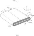
FIG. 1 is a schematic structural diagram of a battery according to some embodiments of this application. -
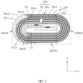
FIG. 2 is a schematic cross-sectional diagram of a battery according to some embodiments of this application. -
FIG. 3 is a partially enlarged schematic diagram of part III of the battery inFIG. 2 according to some embodiments of this application. -
FIG. 4A is a partial top view of part III of the battery inFIG. 2 according to some embodiments of this application. -
FIG. 4B is a partial cross-sectional view of the battery in a direction IV-IV inFIG. 3 according to some embodiments of this application. -
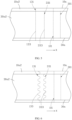
FIG. 5 is a partial top view of part III of the battery inFIG. 2 according to some embodiments of this application. -
FIG. 6 is a partial top view of part III of the battery inFIG. 2 according to some embodiments of this application. -
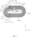
FIG. 7 is a schematic cross-sectional diagram of part III of the battery inFIG. 2 according to some embodiments of this application. -
FIG. 8 is a partially enlarged schematic diagram of part VIII of the battery inFIG. 7 according to some embodiments of this application. -
FIG. 9A is a partial top view of part VIII of the battery inFIG. 7 according to some embodiments of this application. -
FIG. 9B is a partial cross-sectional view of the battery in a direction IX-IX inFIG. 8 according to some embodiments of this application. -
FIG. 10 is a partially enlarged schematic diagram of part VIII of the battery inFIG. 7 according to some embodiments of this application. -
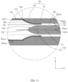
FIG. 11 is a partially enlarged schematic diagram of part VIII of the battery inFIG. 7 according to some embodiments of this application. -
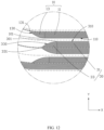
FIG. 12 is a partially enlarged schematic diagram of part XI of the battery inFIG. 2 according to some embodiments of this application. -
FIG. 13 is a partial top view of part XI of the battery inFIG. 2 according to some embodiments of this application. - This application will be further described with reference to the accompanying drawings in the following embodiments.
- The technical solutions in some embodiments of this application are clearly described below in detail. Apparently, the described embodiments are only a part rather than all of some embodiments of this application. Unless otherwise defined, all technical and scientific terms used herein shall have the same meanings as commonly understood by those skilled in the art to which this application belongs. The terms used in the specification of this application are merely intended to describe specific embodiments but not intended to constitute any limitation on this application.
- Some embodiments of this application are described below in detail. However, this application may be embodied in many different forms, and should not be construed as being limited to the example embodiments explained herein. Rather, these example embodiments are provided so that this application can be conveyed to those skilled in the art in a thorough and detailed manner.
- In addition, for brevity and clarity, in the accompanying drawings, various components and layers may be magnified in size or thickness. Throughout the text, the same numerical values represent the same elements. As used herein, the term "and/or" includes any and all combinations of one or more related listed items. In addition, it should be understood that when an element A is referred to as "connecting" an element B, the element A may be directly connected to the element B, or there may be an intermediate element C, and the element A and the element B may be indirectly connected to each other.
- Further, the use of "may" when describing some embodiments of this application refers to "one or more embodiments of this application".
- The terminology used herein is for the purpose of describing specific embodiments and is not intended to limit this application. As used herein, singular forms are intended to also include plural forms, unless otherwise clearly specified. It should be further understood that the term "including", when used in this specification, refers to the presence of the described features, values, steps, operations, elements, and/or components, but does not exclude the presence or addition of one or more other features, values, steps, operations, elements, components, and/or combinations thereof.
- Spatial related terms such as "above" may be used herein for ease of description to describe the relationship between one element or feature and another element (a plurality of elements) or feature (a plurality of features) as illustrated in the figure. It should be understood that, in addition to the directions described in the figures, the spatial related terms are intended to include different directions in the use or operation of devices or apparatus. For example, if a device in the figure is turned over, an element described as "on" or "above" another element or feature should be oriented "below" or "under" the another element or feature. Therefore, the example term "above" may include directions of above and below.
- It should be understood that when an element or layer is described as being "on" another element or layer, "connected to" another element or layer, "coupled to" another element or layer, or "close to" another element or layer, the element or layer may be "directly on" the another element or layer, "directly coupled to" the another element or layer, or "directly connected to" the another element or layer, "directly combined with" the another element or layer, or "directly close to" the another element or layer, or there may be one or more intermediate elements or intermediate layers. In addition, "connection", "connected", or the like may also mean "electrically connected" or the like based on its content understood by those skilled in the art. In addition, when an element, component, zone, layer, and/or portion is described as being "between" two elements, components, zones, layers, and/or portions, it may be the only element, component, zone, layer, and/or portion between the two elements, components, zones, layers, and/or portions, or one or more intermediate elements, components, zones, layers, and/or portions may be present.
- It should be understood that although the terms first, second, third, or the like may be used herein to describe various elements, components, zones, layers, and/or portions, these elements, components, zones, layers, and/or portions should not be limited by these terms. These terms are used to distinguish one element, component, zone, layer, or portion from another element, component, zone, layer, or portion. Therefore, the first element, component, zone, layer, or portion discussed below may be referred to as the second element, component, zone, layer, or portion without departing from the teachings of the example embodiments.
- In this application, a first direction X and a third direction Z are perpendicular to each other and parallel to a main plane of an electrode assembly, and a second direction Y is perpendicular to the main plane of the electrode assembly, that is, a thickness direction of the electrode assembly. The main plane of the electrode assembly is a surface (100B in
FIG. 1 ) of a flat portion of the electrode assembly. The thickness direction of the electrode assembly is a stacking direction of electrode plates in the flat portion of the electrode assembly. - Some embodiments of this application are described in detail below. In absence of conflicts, the following embodiments and features in the embodiments may be combined.
- Referring to
FIGs. 1 and2 , abattery 100 includes anelectrode assembly 100A.FIG. 2 is a cross-section of a plane formed by thebattery 100 inFIG. 1 in directions X and Y Theelectrode assembly 100A includes anegative electrode plate 10A, apositive electrode plate 30A, and aseparator 50 located between thepositive electrode plate 10A and thenegative electrode plate 30A. Theseparator 50 is an electrical insulating material, and ions can pass through theseparator 50. - A positional relationship between the
negative electrode plate 10A and thepositive electrode plate 30A is further described below. - As shown in
FIG. 1 , thenegative electrode plate 10A, theseparator 50, and thepositive electrode plate 30A are stacked to form a stack, and then the stack is wound around a central axis O-O of the third direction Z for multiple times to form theelectrode assembly 100A. - The
electrode assembly 100A includes a flat portion 100AA, and a plurality of bending end portions 100AB in the X direction, and the plurality of bending end portions 100AB are distributed on opposite sides of a center of the flat portion 100AA of thebattery 100 in the X direction, and on the left and right sides inFIG. 2 . - The
positive electrode plate 30A is further described below. - Referring to
FIG. 2 , thepositive electrode plate 30A includes a positive electrodeactive material layer 30 and a positive electrodecurrent collector 30a. The positive electrodeactive material layer 30 is provided on a surface of the positive electrodecurrent collector 30a. - The positive electrode
current collector 30a is conductive and includes a conductive material. The conductive material, for example, may include at least one or more of conductive metals such as aluminum, copper, and nickel, and alloys thereof. In some embodiments, the positive electrodecurrent collector 30a, for example, may include but is not limited to at least one or more of conductive metal sheets such as aluminum meshes, aluminum foil, copper meshes, copper foil, and nickel foil. The positive electrodecurrent collector 30a includes a first face 30aa and a second face 30ab that are disposed back to back with each other. The first face 30aa of the positive electrodecurrent collector 30a includes a first zone 30a1 and a second zone 30a2, and the second face 30ab of the positive electrodecurrent collector 30a includes a first zone 30a1 and a second zone 30a2. The first zones 30a1 are zones where active materials are provided to form an active material layer, and the second zones 30a2 are zones where no active material layer is formed. In some embodiments, the first face 30aa may include two second zones 30a2 that are connected to two ends of the first zone 30a1 of the first face 30aa, and the second face 30ab may include two second zones 30a2 that are connected to two ends of the first zone 30a1 of the second face 30ab. An area of the first zone 30a1 of the first face 30aa may be less than an area of the first zone 30a1 of the second face 30ab. - The positive electrode
active material layer 30 is provided in the first zone 30a1 of the first face 30aa and the first zone 30a1 of the second face 30ab of the positive electrodecurrent collector 30a. The positive electrodeactive material layer 30, for example, may include at least but is not limited to one or more of lithium cobaltate, lithium nickel cobalt manganate, lithium nickel cobalt aluminate, lithium manganate, lithium nickelate, lithium manganese iron phosphate, lithium vanadium phosphate, lithium vanadyl phosphate, lithium iron phosphate, and lithium-rich manganese-based materials. - In some embodiments, a thickness of the positive electrode
current collector 30a may be 3 micrometers to 15 micrometers, and a thickness of the positive electrodeactive material layer 30 may be 80 micrometers to 300 micrometers. - In some embodiments, a ratio of a thickness of the positive electrode
active material layer 30 to a thickness of the positive electrodecurrent collector 30a may be 5 to 30, helping to reduce a proportion of the thickness of the positive electrodecurrent collector 30a to an overall thickness of the battery, thereby helping to increase energy density of the battery. - Referring to
FIG. 3 , the positive electrodeactive material layer 30 includes afirst portion 31 and asecond portion 33 connected to thefirst portion 31 in the first direction X. Thefirst portion 31 includes afirst surface 310, and thesecond portion 33 includes athird surface 330 and afirst end 331. Thefirst surface 310 is connected to thethird surface 330 through afirst connection 301. Thefirst end 331 is an end of thesecond portion 33 opposite from thefirst connection 301, and thefirst end 331 is an end of the positive electrodeactive material layer 30. - A thickness of the
second portion 33 in the second direction Y progressively decreases from thefirst connection 301 to thefirst end 331, the second direction Y being perpendicular to the first direction X. In some embodiments, the thickness of thesecond portion 33 in the second direction Y decreases monotonically from thefirst connection 301 to thefirst end 331, where the thickness may decrease linearly or decrease curvilinearly. - Viewed from the second direction Y, the
first end 331 is located in the flat portion 100AA. - The positive electrode
active material layer 30 is disposed in the first zone 30a1, and the second zone 30a2 is provided on one side of thefirst end 331 opposite from thefirst connection 301 in the first direction X. - The
negative electrode plate 10A is further described below. - Referring to
FIG. 2 , thenegative electrode plate 10A includes a negative electrodeactive material layer 10 and a negative electrodecurrent collector 10a. The negative electrodeactive material layer 10 is provided on a surface of the negative electrodecurrent collector 10a. - The negative electrode
current collector 10a is conductive and includes a conductive material. The conductive material, for example, may include at least one or more of conductive metals such as nickel and copper, and alloys thereof. In some embodiments, the negative electrodecurrent collector 10a, for example, may include but is not limited to at least one or two of conductive metal sheets such as nickel foil and copper foil. The negative electrodecurrent collector 10a includes a first face 10aa and a second face 10ab that are disposed back to back with each other. The first face 10aa of the negative electrodecurrent collector 10a includes a first zone 10a1 and a second zone 10a2, and the second face 10ab of the negative electrodecurrent collector 10a includes a first zone 10a1 and a second zone 10a2. The first zones 10a1 are zones where active materials are provided to form an active material layer, and the second zones 10a2 are zones where no active material layer is formed. In some embodiments, the first face 10aa may include two second zones 10a2 that are connected to two ends of the first zone 10a1 of the first face 10aa, and the second face 10ab may include two second zones 10a2 that are connected to two ends of the first zone 10a1 of the second face 10ab. An area of the first zone 10a1 of the first face 10aa may be greater than an area of the first zone 10a1 of the second face 10ab. - The negative electrode
active material layer 10 is provided in the first zone 10a1 of the first face 10aa and the first zone 10a1 of the second face 10ab of the negative electrodecurrent collector 10a. The negative electrodeactive material layer 10, for example, may include at least but is not limited to one or more of graphite, soft carbon, hard carbon, graphene, meso-carbon microbeads, silicon-based materials, tin-based materials, lithium titanate, or other metals capable of forming alloys with lithium. - In some embodiments, a thickness of the negative electrode
current collector 10a may be 2 micrometers to 13 micrometers, and a thickness of the negative electrodeactive material layer 10 may be 80 micrometers to 300 micrometers. - In some embodiments, a ratio of a thickness of the negative electrode
active material layer 10 to a thickness of the negative electrodecurrent collector 10a may be 5 to 60, helping to reduce a proportion of the thickness of the negative electrodecurrent collector 10a to an overall thickness of the battery, thereby helping to increase energy density of the battery. - Referring to
FIG. 3 , the negative electrodeactive material layer 10 includes athird portion 11 and afourth portion 13 connected to thethird portion 11 in the first direction X. Thethird portion 11 includes asecond surface 110, and thefourth portion 13 includes afourth surface 130 and asecond end 131. Thesecond surface 110 is connected to thefourth surface 130 through asecond connection 101. Thesecond end 131 is an end of thefourth portion 13 opposite from thesecond connection 101, and thesecond end 131 is an end of the negative electrodeactive material layer 10. - In some embodiments, a thickness of the
fourth portion 13 in the second direction Y may progressively decrease from thesecond connection 101 to thesecond end 131. In some embodiments, a thickness of thefourth portion 13 in the second direction Y decreases monotonically from thesecond connection 101 to thesecond end 131, where the thickness may decrease linearly or decrease curvilinearly. - Viewed from the second direction Y, the
second end 131 is located in the flat portion 100AA. The negative electrodeactive material layer 10 is disposed in the first zone 10a1, and the second zone 10a2 is provided on one side of thesecond end 131 opposite from thesecond connection 101 in the first direction X. - In some embodiments, the first face 10aa of the negative electrode
current collector 10a is disposed toward the second face 30ab of the positive electrodecurrent collector 30a, and the second face 10ab of the negative electrodecurrent collector 10a is disposed toward the first face 30aa of the positive electrodecurrent collector 30a. - The
separator 50 is located between the negative electrodeactive material layer 10 and the positive electrodeactive material layer 30. Theseparator 50 includes an electrical insulating material. For example, it may include but is not limited to at least one or more of polyethylene, polypropylene, polyethylene glycol terephthalate, polyimide, and aramid. For example, polyethylene includes at least one component selected from high-density polyethylene, low-density polyethylene, and ultra-high-molecular-weight polyethylene. Particularly, polyethylene and polypropylene have a good effect on preventing short-circuit, and can improve stability of the lithium-ion battery through the shutdown effect. - A surface of the separator may further include a porous layer. The porous layer is arranged on at least one surface of the separator and includes inorganic particles and a binder. The inorganic particles are selected from a combination of one or more of aluminum oxide (Al2O3), silicon oxide (SiO2), magnesium oxide (MgO), titanium oxide (TiO2), hafnium oxide (HfO2), stannic oxide (SnO2), cerium dioxide (CeO2), nickel oxide (NiO), zinc oxide (ZnO), calcium oxide (CaO), zirconium oxide (ZrO2), yttrium oxide (Y2O3), silicon carbide (SiC), boehmite, aluminum hydroxide, magnesium hydroxide, calcium hydroxide, and barium sulfate. The binder may be selected from but is not limited to a combination of one or more of polyvinylidene fluoride, a vinylidene fluoride-hexafluoropropylene copolymer, polyamide, polyacrylonitrile, polyacrylate, polyacrylic acid, polyacrylate, sodium carboxymethyl cellulose, polyvinylpyrrolidone, polyvinyl ether, polymethyl methacrylate, polytetrafluoroethylene, and polyhexafluoropropylene.
- The porous layer can improve heat resistance, oxidation resistance, and electrolyte infiltration performance of the separator, and enhance adhesion between the separator and a positive electrode or negative electrode.
- In some embodiments, the
separator 50 is a film layer including a plurality of holes. As shown inFIG. 2 , each break in theseparator 50 is a hole. - In some embodiments, the
separator 50 in the drawings is in contact with neither the negative electrodeactive material layer 10 nor the positive electrodeactive material layer 30, but in some embodiments, theseparator 50 may be in contact with at least a part of the negative electrodeactive material layer 10 and the positive electrodeactive material layer 30. - An example is used below for description. In the example, the
second end 131 serves as an end of the negative electrodeactive material layer 10 close to an end, that is, part III, of thewound electrode assembly 100A, and thefirst end 331 serves as an end of the positive electrodeactive material layer 30 close to an end of thewound electrode assembly 100A. - The negative electrode
active material layer 10 and the positive electrodeactive material layer 30 are arranged opposite to each other. Specifically, referring toFIG. 3 , thesecond surface 110 and thefirst surface 310 are at least partially arranged opposite to each other. That is, viewed from the second direction Y, thesecond surface 110 and thefirst surface 310 at least partially overlap. In some embodiments, thefourth surface 130 and thethird surface 330 may be at least partially arranged opposite to each other. That is, viewed from the second direction Y, thefourth surface 130 and thethird surface 330 at least partially overlap. In the first direction X, thesecond connection 101 may be located between thefirst connection 301 and thefirst end 331. The thickness of thefourth portion 13 in the second direction Y progressively decreases from thesecond connection 101 to thesecond end 131, and the thickness of thesecond portion 33 in the second direction Y progressively decreases from thefirst connection 301 to thefirst end 331, helping to inhibit lithium precipitation while maintaining energy density of thebattery 100. - In some embodiments, in the first direction X, the
first end 331 may be located between thesecond connection 101 and thesecond end 131. That is, viewed from the second direction Y, thefourth surface 130 and thethird surface 330 at least partially overlap, thereby further helping to inhibit lithium precipitation of the battery. - The negative electrode
active material layer 10 and the positive electrodeactive material layer 30 are separated from each other. A distance from thefirst surface 310 to thesecond surface 110 in the second direction Y is a first distance D1, a distance from thethird surface 330 to thefourth surface 130 in the second direction Y is a second distance D2, and a distance from thethird surface 330 to thesecond surface 110 in the second direction Y is a third distance D3. D1 is different from D2, and D1 is different from D3. Specifically, D2 is greater than D1, D3 is greater than D1, and D3 is different from D2. More specifically, D3 is less than D2. - Referring to
FIG. 4A ,FIG. 5, and FIG. 6 , viewed from the second direction Y, thesecond end 131 and thefirst end 331 may be arranged in parallel or not. Viewed from the second direction Y, thesecond end 131 may be linear or curved in the third direction Z, and thefirst end 331 may also be linear or curved. - In some embodiments, referring to
FIG. 4A , viewed from the second direction Y, thefirst end 331 has a first zone with a first distance E1 from the first zone to thesecond end 131 in the first direction X, and thefirst end 331 may further have a second zone with a second distance E2 from the second zone to thesecond end 131 in the first direction X. E1 and E2 are not equal.FIG. 4B is a partial cross-sectional top view of the battery in a plane formed in the directions X and Z. The cross-section shows the positive electrodeactive material layer 30. InFIG. 4B , a distance from an end of the positive electrodeactive material layer 30 close to thesecond end 131 in the first direction X to thesecond end 131 is greater than a distance from thefirst end 331 to thesecond end 131 in the first direction X. - Specifically, referring to
FIGs. 4A and6 , viewed from the second direction Y, thefirst end 331 may have a plurality ofprotrusions 333. For example, thefirst end 331 may be in but is not limited to a wave or zigzag shape. Similarly, thesecond end 131 may also have a plurality ofprotrusions 133. For example, thesecond end 131 may be in but is not limited to a wave or zigzag shape. - In some embodiments, referring to
FIGs. 7 to 9A , thebattery 100 further includes afirst layer 60, and thefirst layer 60 includes an insulating material. Thefirst layer 60 is capable of impeding ion conduction, for example, blocking or isolating migration of ions. In some embodiments, thefirst layer 60 may be a single-sided adhesive paper or a double-sided adhesive paper. - The
first layer 60 binds thefirst end 331 and thethird surface 330; and the first layer covers thefirst end 331 and thethird surface 330, and inhibits lithium precipitation of the battery by preventing lithium ions generated by the positive electrodeactive material layer 30 from reaching the opposite negative electrodeactive material layer 10. - In some embodiments, the
first layer 60 may further extend from thethird surface 330 to thefirst surface 310 to bind thefirst surface 310 and cover a part of thefirst surface 310, thereby further preventing the lithium ions generated by the positive electrodeactive material layer 30 from reaching the negative electrodeactive material layer 10, thus avoiding lithium precipitation. - In some embodiments, a length of a part of the
first layer 60 bound to thefirst surface 310 in the first direction X may be less than or equal to 5 mm, so as to reduce energy density loss while inhibiting lithium precipitation of the battery. - In some embodiments, the
first layer 60 may further extend from thefirst end 331 to the second zone 30a2 to bind the second zone 30a2 and cover at least a part of the second zone 30a2, so as to help ensure that thefirst layer 60 is still bound to thefirst end 331 when an edge of thefirst layer 60 upwarps, thereby further inhibiting lithium precipitation of the battery. In addition, when thefirst layer 60 is made of an insulating material, thefirst layer 60 covering the second zone 30a2 can further reduce a probability of a short circuit between thepositive electrode plate 30A and thenegative electrode plate 10A. When thefirst layer 60 extends from thefirst end 331 to the second zone 30a2 and covers the second zone 30a2, acrease 65 is correspondingly formed on a surface of thefirst layer 60 opposite from thefirst end 331. Viewed from the second direction Y, thecrease 65 is located between thefirst end 331 and thesecond end 131. -
FIG. 9B is a partial cross-sectional top view of the battery in a plane formed in the directions X and Z. The cross-section shows the positive electrodeactive material layer 30 and thefirst layer 60 bound to the positive electrodeactive material layer 30. InFIG. 9B , a distance from an end of the positive electrodeactive material layer 30 close to thesecond end 131 in the first direction X to thesecond end 131 is greater than a distance from thefirst end 331 to thesecond end 131 in the first direction X. - The
first layer 60 includes athird end 62 and afourth end 64 that are spaced apart and opposite from each other in the first direction X. In the first direction X, thethird end 62 is located on one side of thefirst connection 301, and thefourth end 64 is located on another side of thefirst connection 301. - As shown in
FIG. 7 , viewed from the second direction Y, a distance from thefirst end 331 to thethird end 62 in the first direction X is a fourth distance F1, and a distance from thefirst end 331 to thefourth end 64 in the first direction X is a fifth distance F2. F1 and F2 are not equal. Preferably, F1 is less than F2. - As shown in
FIGs. 9A and 9B , viewed from the second direction Y, a width of thefirst layer 60 in the direction Z is greater than a width of the positive electrodeactive material layer 30 in the direction Z, thereby helping to inhibit lithium precipitation of the battery. Preferably, the width of thefirst layer 60 in the direction Z is greater than a width of thepositive electrode plate 30A in the direction Z, and greater than a width of thenegative electrode plate 10A in the direction Z, thereby helping to further inhibit lithium precipitation of the battery, and helping to further reduce the probability of a short circuit between thepositive electrode plate 30A and thenegative electrode plate 10A. In some embodiments, on the basis that the width of thefirst layer 60 in the direction Z is greater than the width of the positive electrodeactive material layer 30 in the direction Z, the width of thefirst layer 60 in the direction Z may be greater than, less than, or equal to a width of the negative electrodeactive material layer 10 in the direction Z. - In some embodiments, referring to
FIG. 10 , thefirst surface 310 may include athird zone 310a, astep zone 310b, and a fourth zone 310c that are sequentially connected in the first direction X. A thickness H1 of a part of the positive electrodeactive material layer 30 corresponding to the fourth zone 310c in the second direction Y is less than a thickness H2 of a part of the positive electrodeactive material layer 30 corresponding to thethird zone 310a. Viewed from the second direction Y, the fourth zone 310c is located between thestep zone 310b and thesecond connection 101. Thefirst layer 60 covers the fourth zone 310c, helping to reduce impact of disposing thefirst layer 60 on the thickness of the battery, thus helping to improve the energy density of the battery. - In some embodiments, in the second direction Y, the thickness H1 of the part of the positive electrode
active material layer 30 corresponding to the fourth zone 310c in the second direction Y is greater than a height H3 of thestep zone 310b. - In some embodiments, as shown in
FIG. 10 , thestep zone 310b is a step surface connecting thethird zone 310a and the fourth zone 310c, and may be an inclined curved surface. - In some embodiments, a thickness H4 of the
first layer 60 in the second direction Y may be greater than the height H3 of thestep zone 310b in the second direction Y. Herein, the height of thestep zone 310b refers to a distance in the second direction Y from a junction between thestep zone 310b and thethird zone 310a to a junction between thestep zone 310b and the fourth zone 310c. - In some embodiments, the
first layer 60 may also cover thestep zone 310b, or cover thestep zone 310b and a part of thethird zone 310a. - A part of the
first layer 60 located in the fourth zone 310c includes afifth surface 66. Thefifth surface 66 is opposite from the fourth zone 310c. In some embodiments, thefifth surface 66 includes a part having a distance G1 to thethird zone 310a in the second direction Y greater than a distance G2 to thesecond surface 110 in the second direction Y. - In some embodiments, the
first surface 310 may alternatively be a flat surface. - In some embodiments, referring to
FIG. 11 , viewed from the second direction Y, thesecond end 131 of the negative electrodeactive material layer 10 may be located between thefirst end 331 and thefirst connection 301 in the first direction X. In some embodiments, viewed from the second direction Y, thefirst connection 301 of the positive electrodeactive material layer 30 may be located between thesecond connection 301 and thesecond end 131 in the first direction X. - In some embodiments, referring to
FIGs. 12 and13 , thesecond end 131 may alternatively be an end of the negative electrodeactive material layer 10 close to an initial section of thewound electrode assembly 100A, and thefirst end 331 may alternatively be an end of the positive electrodeactive material layer 30 close to an initial section of thewound electrode assembly 100A. - According to the battery in this application, the thickness of the second portion in the second direction decreases from the first connection to the first end, thereby helping to improve energy density of the battery; the first layer blocking migration of ions binds the first end, the second portion, and the first surface; and the first layer covers the first end, the second portion, and the part of the first surface, thereby helping to inhibit lithium ions generated by the positive electrode active material layer from reaching the negative electrode active material layer, and thus helping to inhibit lithium precipitation of the battery. Therefore, the structure of the battery in this application helps to inhibit lithium precipitation while maintaining energy density of the battery.
- In addition, a person of ordinary skill in the art can make various other corresponding changes and modifications according to the technical concept of this application, and all such changes and modifications should fall within the protection scope of this application.
| Battery |
| 100 | |
| |
100A |
| |
100B |
| |
10A |
| | 30A |
| Separator | |
| 50 | |
| Negative electrode |
10 |
| Negative electrode |
10a |
| First zone | 10a1, 30a1 |
| Second zone | 10a2, 30a2 |
| First direction | X |
| |
11 |
| |
13 |
| |
130 |
| |
131 |
| |
110 |
| |
101 |
| Second direction | Y |
| Third direction | Z |
| Positive electrode |
30 |
| Positive electrode |
30a |
| |
31 |
| |
33 |
| |
330 |
| |
331 |
| |
310 |
| |
301 |
| Central axis | O-O |
| Flat portion | 100AA |
| Bending end | 100AB |
| Protrusion | |
| 333, 133 | |
| |
60 |
| |
62 |
| |
64 |
| |
|
| Step zone | |
| 310b | |
| Fourth zone | 310c |
| |
66 |
| First face | 10aa, 30aa |
| Second face | 10ab, 30ab |
| Crease | 65 |
Claims (18)
- A battery, comprising a positive electrode active material layer, a negative electrode active material layer and a separator disposed between the positive electrode active material layer and the negative electrode active material layer; characterized in that,in a first direction, the positive electrode active material layer comprises a first portion and a second portion connected to the first portion, the second portion comprises a first end, the first portion comprises a first surface, the first surface is connected to the second portion through a first connection, the first end is an end of the positive electrode active material layer, and a thickness of the second portion in a second direction decreases from the first connection to the first end; the second direction being perpendicular to the first direction;the negative electrode active material layer comprises a third portion and a second end located on one side of the third portion in the first direction, and the third portion comprises a second surface having at least a part arranged opposite to the first surface;the battery further comprises a first layer; the first layer binds the first end, the second portion and the first surface; and the first layer covers the first end, the second portion and a part of the first surface; andthe first layer is configured to impede ion conduction.
- The battery according to claim 1, characterized in that, a length of a part of the first layer bound to the first surface in the first direction is less than or equal to 5 mm.
- The battery according to claim 1, characterized in that, the negative electrode active material layer further comprises a fourth portion connected to the third portion in the first direction, the fourth portion is connected to the second surface through a second connection, and an end of the fourth portion opposite from the second connection is the second end; and a thickness of the fourth portion in the second direction decreases from the second connection to the second end; and
in the first direction, the second connection is located between the first connection and the first end. - The battery according to claim 3, characterized in that,the second portion comprises a third surface;the fourth portion comprises a fourth surface;the third surface and the first surface are connected through the first connection;the fourth surface and the second surface are connected through the second connection;the third surface and the fourth surface are at least partially arranged opposite to each other; andthe first layer is bound to and covers the third surface.
- The battery according to claim 3, characterized in that, an orthographic projection of the first end in the second direction falls within an orthographic projection of the fourth portion in the first direction.
- The battery according to claim 4, characterized in that, the first surface and the second surface at least partially overlap in the second direction, the third surface and the fourth surface at least partially overlap in the second direction, and the second surface and the third surface at least partially overlap in the second direction.
- The battery according to claim 4, characterized in that, a distance from the first surface to the second surface in the second direction is a first distance, and a distance from the third surface to the fourth surface in the second direction is a second distance, wherein the first distance is different from the second distance.
- The battery according to claim 7, characterized in that, the first distance is less than the second distance.
- The battery according to claim 7, characterized in that, a distance from the third surface to the second surface in the second direction is a third distance, and the third distance is greater than the first distance.
- The battery according to claim 9, characterized in that, the third distance is less than the second distance.
- The battery according to claim 1, characterized in that, viewed from the second direction, the first end has a first zone and a second zone; wherein a first distance from the first zone to the second end in the first direction is different from a second distance from the second zone to the second end in the first direction.
- The battery according to claim 1, characterized in that, viewed from the second direction, the first end has a plurality of protrusions.
- The battery according to claim 6, characterized in that, in the first direction, the first layer comprises a third end and a fourth end opposite from each other; andin the first direction, the third end is located on one side of the first connection, and the fourth end is located on another side of the first connection; andviewed from the second direction, a distance from the first end to the third end in the first direction is a fourth distance, a distance from the first end to the fourth end in the first direction is a fifth distance, and the fourth distance is different from the fifth distance.
- The battery according to claim 13, characterized in that, the fourth distance is less than the fifth distance.
- The battery according to claim 1, characterized in that, the first surface comprises a third zone, a step zone, and a fourth zone sequentially connected in the first direction; andin the first direction, the third zone is located on one side of the step zone opposite from the first end;a thickness of the fourth zone in the second direction is less than a thickness of the third zone in the second direction; anda part of the first layer that is bound to the first surface covers the fourth zone.
- The battery according to claim 15, characterized in that, a thickness of the first layer in the second direction is greater than a height of the step zone in the second direction.
- The battery according to claim 16, characterized in that, a part of the first layer located in the fourth zone comprises a fifth surface, the fifth surface is opposite from the fourth zone, and
the fifth surface comprises a part having a distance to the third zone in the second direction greater than a distance to the second surface in the second direction. - The battery according to claim 1, characterized in that, the first layer is a single-sided adhesive paper or a double-sided adhesive paper.
Applications Claiming Priority (1)
| Application Number | Priority Date | Filing Date | Title |
|---|---|---|---|
| PCT/CN2021/076081 WO2022165849A1 (en) | 2021-02-08 | 2021-02-08 | Battery |
Publications (2)
| Publication Number | Publication Date |
|---|---|
| EP4207428A1 true EP4207428A1 (en) | 2023-07-05 |
| EP4207428A4 EP4207428A4 (en) | 2024-07-17 |
Family
ID=82740719
Family Applications (1)
| Application Number | Title | Priority Date | Filing Date |
|---|---|---|---|
| EP21923859.9A Pending EP4207428A4 (en) | 2021-02-08 | 2021-02-08 | BATTERY |
Country Status (3)
| Country | Link |
|---|---|
| US (1) | US20230238520A1 (en) |
| EP (1) | EP4207428A4 (en) |
| WO (1) | WO2022165849A1 (en) |
Families Citing this family (1)
| Publication number | Priority date | Publication date | Assignee | Title |
|---|---|---|---|---|
| US12620592B2 (en) | 2018-03-05 | 2026-05-05 | The Research Foundation For The State University Of New York | ϵ-VOPO4 cathode production, and applications thereof |
Family Cites Families (6)
| Publication number | Priority date | Publication date | Assignee | Title |
|---|---|---|---|---|
| JP5378718B2 (en) * | 2007-07-09 | 2013-12-25 | パナソニック株式会社 | Electrode plate for non-aqueous electrolyte secondary battery and non-aqueous electrolyte secondary battery using the same |
| JP6249493B2 (en) * | 2013-03-07 | 2017-12-20 | Necエナジーデバイス株式会社 | Non-aqueous electrolyte secondary battery |
| JP6674657B2 (en) * | 2016-03-04 | 2020-04-01 | 株式会社Gsユアサ | Storage element |
| JP7002094B2 (en) * | 2016-10-31 | 2022-01-20 | 株式会社エンビジョンAescジャパン | Electrodes for electrochemical devices, electrochemical devices, and their manufacturing methods |
| JP6961398B2 (en) * | 2017-06-14 | 2021-11-05 | 株式会社エンビジョンAescジャパン | Lithium-ion secondary battery element and lithium-ion secondary battery |
| CN208690417U (en) * | 2018-08-27 | 2019-04-02 | 宁德新能源科技有限公司 | Battery core and electrochemical appliance |
-
2021
- 2021-02-08 EP EP21923859.9A patent/EP4207428A4/en active Pending
- 2021-02-08 WO PCT/CN2021/076081 patent/WO2022165849A1/en not_active Ceased
-
2023
- 2023-03-30 US US18/193,192 patent/US20230238520A1/en active Pending
Also Published As
| Publication number | Publication date |
|---|---|
| EP4207428A4 (en) | 2024-07-17 |
| US20230238520A1 (en) | 2023-07-27 |
| WO2022165849A1 (en) | 2022-08-11 |
Similar Documents
| Publication | Publication Date | Title |
|---|---|---|
| US20240194939A1 (en) | All-solid-state battery | |
| CN209822691U (en) | a battery | |
| KR101650417B1 (en) | Secondary battery having jelly roll type electrode assembly with intermittent non-coated positive electrode active material | |
| EP3664192A1 (en) | Electrode assembly and battery | |
| CN112802993B (en) | Battery | |
| CN114586217A (en) | Electrochemical device and electronic device including the same | |
| CN109411643B (en) | Battery pack | |
| US12224405B2 (en) | Electrode assembly, secondary battery, and battery-powered apparatus | |
| CN214203736U (en) | Battery with a battery cell | |
| EP3910702B1 (en) | Electrode plate, cell, and electrochemical device | |
| JP2020126769A (en) | Secondary battery | |
| KR20220109177A (en) | Electrode assembly with external fixing frame and lithium secondary battery comprising thereof | |
| JP5676095B2 (en) | Multilayer secondary battery | |
| CN214203737U (en) | Battery | |
| US20230238520A1 (en) | Battery and electronic device | |
| US20230238655A1 (en) | Battery | |
| CN213340472U (en) | Roll cores, batteries and electronic products | |
| CN119542689B (en) | Electrochemical devices and electronic devices | |
| CN112802994B (en) | Battery | |
| CN116190672A (en) | Current collector, electrode sheet and battery | |
| WO2023141776A1 (en) | Battery and electronic device comprising same | |
| KR101367975B1 (en) | Electrode assembly, method of manufacturing the same, and battery having the same | |
| CN114843576B (en) | Cells and Batteries | |
| CN220065741U (en) | Pole piece and battery | |
| CN223693140U (en) | Positive plate, battery cell and battery |
Legal Events
| Date | Code | Title | Description |
|---|---|---|---|
| STAA | Information on the status of an ep patent application or granted ep patent |
Free format text: STATUS: THE INTERNATIONAL PUBLICATION HAS BEEN MADE |
|
| PUAI | Public reference made under article 153(3) epc to a published international application that has entered the european phase |
Free format text: ORIGINAL CODE: 0009012 |
|
| STAA | Information on the status of an ep patent application or granted ep patent |
Free format text: STATUS: REQUEST FOR EXAMINATION WAS MADE |
|
| 17P | Request for examination filed |
Effective date: 20230330 |
|
| AK | Designated contracting states |
Kind code of ref document: A1 Designated state(s): AL AT BE BG CH CY CZ DE DK EE ES FI FR GB GR HR HU IE IS IT LI LT LU LV MC MK MT NL NO PL PT RO RS SE SI SK SM TR |
|
| DAV | Request for validation of the european patent (deleted) | ||
| DAX | Request for extension of the european patent (deleted) | ||
| A4 | Supplementary search report drawn up and despatched |
Effective date: 20240619 |
|
| RIC1 | Information provided on ipc code assigned before grant |
Ipc: H01M 4/02 20060101ALI20240613BHEP Ipc: H01M 10/0525 20100101ALI20240613BHEP Ipc: H01M 10/04 20060101ALI20240613BHEP Ipc: H01M 4/62 20060101ALI20240613BHEP Ipc: H01M 4/13 20100101ALI20240613BHEP Ipc: H01M 10/0587 20100101AFI20240613BHEP |