EP4207396A1 - Solid polymer electrolyte fuel cell stack - Google Patents
Solid polymer electrolyte fuel cell stack Download PDFInfo
- Publication number
- EP4207396A1 EP4207396A1 EP21861533.4A EP21861533A EP4207396A1 EP 4207396 A1 EP4207396 A1 EP 4207396A1 EP 21861533 A EP21861533 A EP 21861533A EP 4207396 A1 EP4207396 A1 EP 4207396A1
- Authority
- EP
- European Patent Office
- Prior art keywords
- catalyst layer
- flow channel
- gas flow
- polymer electrolyte
- fuel cell
- Prior art date
- Legal status (The legal status is an assumption and is not a legal conclusion. Google has not performed a legal analysis and makes no representation as to the accuracy of the status listed.)
- Pending
Links
Images


Classifications
-
- H—ELECTRICITY
- H01—ELECTRIC ELEMENTS
- H01M—PROCESSES OR MEANS, e.g. BATTERIES, FOR THE DIRECT CONVERSION OF CHEMICAL ENERGY INTO ELECTRICAL ENERGY
- H01M8/00—Fuel cells; Manufacture thereof
- H01M8/10—Fuel cells with solid electrolytes
- H01M8/1004—Fuel cells with solid electrolytes characterised by membrane-electrode assemblies [MEA]
- H01M8/1006—Corrugated, curved or wave-shaped MEA
-
- H—ELECTRICITY
- H01—ELECTRIC ELEMENTS
- H01M—PROCESSES OR MEANS, e.g. BATTERIES, FOR THE DIRECT CONVERSION OF CHEMICAL ENERGY INTO ELECTRICAL ENERGY
- H01M8/00—Fuel cells; Manufacture thereof
- H01M8/02—Details
- H01M8/0202—Collectors; Separators, e.g. bipolar separators; Interconnectors
- H01M8/023—Porous and characterised by the material
-
- Y—GENERAL TAGGING OF NEW TECHNOLOGICAL DEVELOPMENTS; GENERAL TAGGING OF CROSS-SECTIONAL TECHNOLOGIES SPANNING OVER SEVERAL SECTIONS OF THE IPC; TECHNICAL SUBJECTS COVERED BY FORMER USPC CROSS-REFERENCE ART COLLECTIONS [XRACs] AND DIGESTS
- Y02—TECHNOLOGIES OR APPLICATIONS FOR MITIGATION OR ADAPTATION AGAINST CLIMATE CHANGE
- Y02E—REDUCTION OF GREENHOUSE GAS [GHG] EMISSIONS, RELATED TO ENERGY GENERATION, TRANSMISSION OR DISTRIBUTION
- Y02E60/00—Enabling technologies; Technologies with a potential or indirect contribution to GHG emissions mitigation
- Y02E60/30—Hydrogen technology
- Y02E60/50—Fuel cells
Definitions
- Embodiments disclosed herein relate to a polymer electrolyte fuel cell stack.
- a fuel cell stack using a polymer electrolyte membrane having proton conductivity as an electrolyte is constituted by constituting a single cell (unit cell) by disposing electrically conductive separators each provided with a gas flow channel on both sides of a membrane electrode assembly (MEA) in which an electrolyte membrane is sandwiched by an anode electrode and a cathode electrode, and stacking a plurality of single cells.
- MEA membrane electrode assembly
- Patent Document 1 proposes a structure in which a substantial effective area is increased by providing wavy unevenness on an electrolyte membrane surface and a reaction membrane.
- Patent Document 1 Patent Publication No. 2831061
- the above-described conventional technique has succeeded in, by providing the wavy unevenness on the electrolyte membrane surface and the reaction membrane, increasing a contact area, that is, the substantial effective area to improve the performances.
- a level of the improvement is limited to an increase of 50% in limiting current density as compared with a flat surface, which has left a problem of failing to greatly improve the performances.
- the present invention has been made to solve the above-described problem, and it is an object to provide a polymer electrolyte fuel cell stack being capable of greatly improving the performances per unit projected area, and being simple and low-cost.
- a polymer electrolyte fuel cell stack according to an embodiment will be hereinafter described in reference to the drawings.
- Fig. 1 schematically illustrates a schematic configuration of a polymer electrolyte fuel cell stack 100 of the embodiment
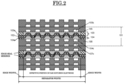
- Fig. 2 illustrates a configuration of an A-A' cross section of the polymer electrolyte fuel cell stack 100 in Fig. 1
- Fig. 3 illustrates the enlarged configuration of the A-A' cross section in Fig. 1 .
- a unit cell (single cell) 101 is constituted by a membrane-electrode assembly (MEA) constituted of a polymer electrolyte membrane 102, an anode electrode 103, and a cathode electrode 104, a fuel gas flow channel-attached separator 105, and an oxidant gas flow channel-attached separator 106.
- MEA membrane-electrode assembly
- a fuel gas flow channel 103c is provided, and its end portion is open on a side surface of the fuel gas flow channel-attached separator 105.
- an oxidant gas flow channel 104c is provided, and a cooling water flow channel 107c is provided in the other surface thereof, and their end portions are open on a side surface of the oxidant gas flow channel-attached separator 106.
- a plurality of the unit cells (single cells) 101 are stacked to constitute a stack.
- an air (oxidant gas) inlet-cooling water outlet manifold having an air (oxidant gas) inlet manifold 110 and a cooling water outlet manifold 111
- an air (oxidant gas) outlet-cooling water inlet manifold having an air (oxidant gas) outlet manifold 112 and a cooling water inlet manifold 113
- a fuel inlet manifold 114, and a fuel outlet manifold 115 are provided.
- the fuel gas flow channel communicates with the air (oxidant gas) flow channel, the fuel gas flow channel, and the cooling water flow channel, supply and discharge fuel and air (oxidant gas) necessary for reaction to and from the membrane-electrode assembly (MEA), and supply cooling water at a predetermined flow rate to remove heat generated with the reaction.
- air oxidant gas
- MEA membrane-electrode assembly
- the membrane-electrode assembly is constituted by disposing an anode catalyst layer 103a and a cathode catalyst layer 104a on both sides of the polymer electrolyte membrane 102, and disposing an anode gas diffusion layer 1031 and a cathode gas diffusion layer 1041 on further outer sides thereof.
- the polymer electrolyte membrane 102 requires ion conductivity and a gas barrier property, and is extended to the same size as that of the fuel gas flow channel-attached separator 105 and the oxidant gas flow channel-attached separator 106 for prevention of mixture of a reaction gas.
- the gas diffusion layers have the next smaller size than the fuel gas flow channel-attached separator 105, the oxidant gas flow channel-attached separator 106, and the polymer electrolyte membrane 102, and an edge seal member 109 sealing the reaction gas is disposed around them.
- the edge seal member 109 is disposed further outside than grooves in the end portions of the gas flow channels.
- the polymer electrolyte membrane 102, the anode catalyst layer 103a, and the cathode catalyst layer 104a are provided with a height difference in a cell thickness direction. That is, as illustrated in Fig. 3 , they are formed in an uneven shape in a fixed period P to have a configuration provided with a height difference H when a cross section of the membrane-electrode assembly (MEA) of the fuel cell stack is seen. Further, at an unevenness turning portion, an angle ⁇ of an inclined plane to a perpendicular direction (for example, approximately 15°) is provided. Accordingly, a cross section of the polymer electrolyte membrane 102, the anode catalyst layer 103a, and the cathode catalyst layer 104a is formed in a trapezoidal wave shape in a thickness direction.
- MEA membrane-electrode assembly
- the above-described angle ⁇ need not be necessarily provided, or the angle ⁇ may be set to 0°.
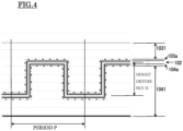
- a cross section of the polymer electrolyte membrane 102, the anode catalyst layer 103a, and the cathode catalyst layer 104a has an angle of 90° at the unevenness turning portion to be formed in a rectangular wave shape in the thickness direction.
- the height difference H is set to be larger than 1/2 of the period P (a width of a portion at a fixed height in Fig. 4 ), that is, is set to H > P / 2 . This allows a later-described effective area to be increased.
- a period of a groove shape of the oxidant gas flow channel 104c and the fuel gas flow channel 103c is the same as a period of the uneven shape formed by the polymer electrolyte membrane 102, the anode catalyst layer 103a, and the cathode catalyst layer 104a in the membrane-electrode assembly (MEA), and the anode catalyst layer 103a is close to a groove portion of the fuel gas flow channel 103c, and the cathode catalyst layer 104a is close to a bank portion of the oxidant gas flow channel 104c is employed.
- MEA membrane-electrode assembly
- the fuel gas flow channel-attached separator 105 and the oxidant gas flow channel-attached separator 106 are composed of a conductive porous material.
- setting a cooling water pressure in the cooling water flow channel 107c to be lower than pressures of a fuel gas in the fuel gas flow channel 103c and an oxidant gas in the oxidant gas flow channel 104c allows water generated by a fuel cell reaction to be discharged through the separator into cooling water flowing through the cooling water flow channel 107c.
- the configuration such that the cathode catalyst layer 104a is close to the bank portion of the oxidant gas flow channel 104c allows water accumulated in the cathode gas diffusion layer in contact with the bank portion to be discharged rapidly, which accelerates the reaction in the groove portion to obtain the effect of improving output as a whole.
- the anode catalyst layer 103a is close to a bank portion of the fuel gas flow channel 103c
- the cathode catalyst layer 104a is close to a groove portion of the oxidant gas flow channel 104c.
- Table 1 presents a comparison of dimensions of catalyst layers between a conventional fuel cell stack and fuel cell stacks in Example 1a and Example 1b. Note that in each of Example 1a and Example 1b, a shape of the polymer electrolyte membrane 102, the anode catalyst layer 103a, and the cathode catalyst layer 104a is the trapezoidal wave shape illustrated in Fig. 3 .
- Example 1a Separator width 140 mm 140 mm 140 mm Separator length 200 mm 200 mm 200 mm Edge seal width 10 mm 10 mm 10 mm
- Electrolyte membrane • catalyst layer period P - 0.5 mm 0.15 mm
- Electrolyte membrane • catalyst layer height difference H 0 mm 0.2 mm 0.1 mm
- Electrolyte membrane • catalyst layer angle ⁇ - 15 degrees 15 degrees
- Catalyst layer length 180 mm 180 mm 180 Effective area 216 cm 2 348 cm 2 436 cm 2 Effective area conventional ratio 1 1.6 2.0
- the above configuration allows the electrolyte membrane and the anode and cathode catalyst layers to be periodically provided with the height difference in the cell thickness direction, that is, the effective portion for reaction to be extended, which improves an output of the fuel cell per unit volume.
- Fig. 4 illustrates an enlarged configuration, similar to that in Fig. 3 , of a cross section of a membrane-electrode assembly (MEA) of a fuel cell stack.
- the polymer electrolyte membrane 102, the anode catalyst layer 103a, and the cathode catalyst layer 104a in the membrane-electrode assembly (MEA) are provided with a height difference in a cell thickness direction. In this case, they are formed in an uneven shape in a fixed period P to be provided with the height difference H.
- Table 2 presents a comparison of dimensions of the catalyst layers between the conventional fuel cell stack and the fuel cell stacks according to Examples 2.
- a width of the catalyst layers was extended to increase the effective area by 288 cm 2 (130%) (this case results in H > P/2.).
- periodically providing the electrolyte membrane and the anode and cathode catalyst layers with the height difference in the cell thickness direction allows the effective portion for reaction to be extended, which improves the output of the fuel cell per unit volume.
Landscapes
- Life Sciences & Earth Sciences (AREA)
- Engineering & Computer Science (AREA)
- Manufacturing & Machinery (AREA)
- Sustainable Development (AREA)
- Sustainable Energy (AREA)
- Chemical & Material Sciences (AREA)
- Chemical Kinetics & Catalysis (AREA)
- Electrochemistry (AREA)
- General Chemical & Material Sciences (AREA)
- Fuel Cell (AREA)
Abstract
Description
- Embodiments disclosed herein relate to a polymer electrolyte fuel cell stack.
- A fuel cell stack using a polymer electrolyte membrane having proton conductivity as an electrolyte is constituted by constituting a single cell (unit cell) by disposing electrically conductive separators each provided with a gas flow channel on both sides of a membrane electrode assembly (MEA) in which an electrolyte membrane is sandwiched by an anode electrode and a cathode electrode, and stacking a plurality of single cells.
- In general, the polymer electrolyte membrane, the anode electrode, and the cathode electrode constituting the membrane electrode assembly (MEA) are all stacked in a flat-plate shape, that is, in a sheet shape, and its effective area is specified by an effective area of the anode electrode and the cathode electrode. Performances, that is, a cell voltage and an electric current, per unit area in the effective area are constant in a material having the same composition, and to increase a fuel cell output power, an attempt has been made to select cell materials having higher activity, lower electrical resistance, and more excellent gas diffusibility to improve the performances per unit area.
- Regarding a method for improving the performances per unit area, Patent Document 1 proposes a structure in which a substantial effective area is increased by providing wavy unevenness on an electrolyte membrane surface and a reaction membrane.
- Patent Document 1: Patent Publication No.
2831061 - The above-described conventional technique has succeeded in, by providing the wavy unevenness on the electrolyte membrane surface and the reaction membrane, increasing a contact area, that is, the substantial effective area to improve the performances. However, a level of the improvement is limited to an increase of 50% in limiting current density as compared with a flat surface, which has left a problem of failing to greatly improve the performances.
- The present invention has been made to solve the above-described problem, and it is an object to provide a polymer electrolyte fuel cell stack being capable of greatly improving the performances per unit projected area, and being simple and low-cost.
- A polymer electrolyte fuel cell stack of an embodiment constitutes a stack by stacking a plurality of basic components, the basic component including: a unit cell constituted by disposing an anode catalyst layer including an anode catalyst having hydrogen-oxidation ability on one surface of a polymer electrolyte membrane, disposing a cathode catalyst layer including a cathode catalyst having oxidation-reduction ability on the other surface of the polymer electrolyte membrane, and disposing respective gas diffusion layers in contact with the anode catalyst layer and the cathode catalyst layer; and a separator disposed in contact with each of the gas diffusion layers, provided with a fuel gas flow channel or an oxidant gas flow channel, and composed of an electrically conductive material, in which the polymer electrolyte membrane, the anode catalyst layer, and the cathode catalyst layer are formed in a trapezoidal wave shape or a rectangular wave shape having a repeating uneven shape in a thickness direction in a fixed period.
-
- [
Fig. 1 ] a view schematically illustrating a schematic configuration of a polymer electrolyte fuel cell stack of an embodiment. - [
Fig. 2 ] a view illustrating a configuration of an A-A' cross section of the polymer electrolyte fuel cell stack inFig. 1 . - [
Fig. 3 ] an enlarged view illustrating the configuration of the A-A' cross section of the polymer electrolyte fuel cell stack inFig. 1 . - [
Fig. 4 ] an enlarged view illustrating a configuration of an A-A' cross section of a polymer electrolyte fuel cell stack in Examples 2. - A polymer electrolyte fuel cell stack according to an embodiment will be hereinafter described in reference to the drawings.
-
Fig. 1 schematically illustrates a schematic configuration of a polymer electrolytefuel cell stack 100 of the embodiment,Fig. 2 illustrates a configuration of an A-A' cross section of the polymer electrolytefuel cell stack 100 inFig. 1 , andFig. 3 illustrates the enlarged configuration of the A-A' cross section inFig. 1 . - As illustrated in
Fig. 2 , a unit cell (single cell) 101 is constituted by a membrane-electrode assembly (MEA) constituted of apolymer electrolyte membrane 102, ananode electrode 103, and acathode electrode 104, a fuel gas flow channel-attachedseparator 105, and an oxidant gas flow channel-attachedseparator 106. - In one surface of the fuel gas flow channel-attached
separator 105, a fuelgas flow channel 103c is provided, and its end portion is open on a side surface of the fuel gas flow channel-attachedseparator 105. In one surface of the oxidant gas flow channel-attachedseparator 106, an oxidantgas flow channel 104c is provided, and a coolingwater flow channel 107c is provided in the other surface thereof, and their end portions are open on a side surface of the oxidant gas flow channel-attachedseparator 106. - A plurality of the unit cells (single cells) 101 are stacked to constitute a stack. As illustrated in
Fig. 1 , on side surfaces of the stack, an air (oxidant gas) inlet-cooling water outlet manifold having an air (oxidant gas) inletmanifold 110 and a coolingwater outlet manifold 111, an air (oxidant gas) outlet-cooling water inlet manifold having an air (oxidant gas)outlet manifold 112 and a coolingwater inlet manifold 113, afuel inlet manifold 114, and afuel outlet manifold 115 are provided. Further, they communicate with the air (oxidant gas) flow channel, the fuel gas flow channel, and the cooling water flow channel, supply and discharge fuel and air (oxidant gas) necessary for reaction to and from the membrane-electrode assembly (MEA), and supply cooling water at a predetermined flow rate to remove heat generated with the reaction. - As illustrated in
Fig. 2 andFig. 3 , the membrane-electrode assembly (MEA) is constituted by disposing ananode catalyst layer 103a and acathode catalyst layer 104a on both sides of thepolymer electrolyte membrane 102, and disposing an anodegas diffusion layer 1031 and a cathodegas diffusion layer 1041 on further outer sides thereof. Thepolymer electrolyte membrane 102 requires ion conductivity and a gas barrier property, and is extended to the same size as that of the fuel gas flow channel-attachedseparator 105 and the oxidant gas flow channel-attachedseparator 106 for prevention of mixture of a reaction gas. - The gas diffusion layers have the next smaller size than the fuel gas flow channel-attached
separator 105, the oxidant gas flow channel-attachedseparator 106, and thepolymer electrolyte membrane 102, and an edge seal member 109 sealing the reaction gas is disposed around them. The edge seal member 109 is disposed further outside than grooves in the end portions of the gas flow channels. - In this embodiment, the
polymer electrolyte membrane 102, theanode catalyst layer 103a, and thecathode catalyst layer 104a are provided with a height difference in a cell thickness direction. That is, as illustrated inFig. 3 , they are formed in an uneven shape in a fixed period P to have a configuration provided with a height difference H when a cross section of the membrane-electrode assembly (MEA) of the fuel cell stack is seen. Further, at an unevenness turning portion, an angle θ of an inclined plane to a perpendicular direction (for example, approximately 15°) is provided. Accordingly, a cross section of thepolymer electrolyte membrane 102, theanode catalyst layer 103a, and thecathode catalyst layer 104a is formed in a trapezoidal wave shape in a thickness direction. - However, the above-described angle θ need not be necessarily provided, or the angle θ may be set to 0°. In this case, as illustrated in
Fig. 4 , a cross section of thepolymer electrolyte membrane 102, theanode catalyst layer 103a, and thecathode catalyst layer 104a has an angle of 90° at the unevenness turning portion to be formed in a rectangular wave shape in the thickness direction. As described above, for either the trapezoidal wave shape or the rectangular wave shape, it is preferable that the height difference H is set to be larger than 1/2 of the period P (a width of a portion at a fixed height inFig. 4 ), that is, is set to
- Here, in this embodiment, as illustrated in
Fig. 2 , the configuration such that a period of a groove shape of the oxidantgas flow channel 104c and the fuelgas flow channel 103c is the same as a period of the uneven shape formed by thepolymer electrolyte membrane 102, theanode catalyst layer 103a, and thecathode catalyst layer 104a in the membrane-electrode assembly (MEA), and theanode catalyst layer 103a is close to a groove portion of the fuelgas flow channel 103c, and thecathode catalyst layer 104a is close to a bank portion of the oxidantgas flow channel 104c is employed. - In addition, in this embodiment, the fuel gas flow channel-attached
separator 105 and the oxidant gas flow channel-attachedseparator 106 are composed of a conductive porous material. In this case, setting a cooling water pressure in the coolingwater flow channel 107c to be lower than pressures of a fuel gas in the fuelgas flow channel 103c and an oxidant gas in the oxidantgas flow channel 104c allows water generated by a fuel cell reaction to be discharged through the separator into cooling water flowing through the coolingwater flow channel 107c. Moreover, the configuration such that thecathode catalyst layer 104a is close to the bank portion of the oxidantgas flow channel 104c allows water accumulated in the cathode gas diffusion layer in contact with the bank portion to be discharged rapidly, which accelerates the reaction in the groove portion to obtain the effect of improving output as a whole. Note that it is also acceptable that theanode catalyst layer 103a is close to a bank portion of the fuelgas flow channel 103c, and thecathode catalyst layer 104a is close to a groove portion of the oxidantgas flow channel 104c. - Table 1 presents a comparison of dimensions of catalyst layers between a conventional fuel cell stack and fuel cell stacks in Example 1a and Example 1b. Note that in each of Example 1a and Example 1b, a shape of the
polymer electrolyte membrane 102, theanode catalyst layer 103a, and thecathode catalyst layer 104a is the trapezoidal wave shape illustrated inFig. 3 .[Table 1] Conventional example Example 1a Example 1b Separator width 140 mm 140 mm 140 mm Separator length 200 mm 200 mm 200 mm Edge seal width 10 mm 10 mm 10 mm Electrolyte membrane • catalyst layer period P - 0.5 mm 0.15 mm Electrolyte membrane • catalyst layer height difference H 0 mm 0.2 mm 0.1 mm Electrolyte membrane • catalyst layer angle θ - 15 degrees 15 degrees Catalyst layer effective width 120 mm 193 mm 242 mm Catalyst layer length 180 mm 180 mm 180 Effective area 216 cm2 348 cm2 436 cm2 Effective area conventional ratio 1 1.6 2.0 - In the conventional fuel cell stack, an electrolyte membrane and catalyst layers were formed in a flat-plate shape, and a catalyst effective area was 216 cm2. In the fuel cell stack in Example 1a, by providing unevenness in a period P = 0.5 mm, in a height difference H = 0.2 mm, and at an angle θ = 15 degrees, a width of the catalyst layers was extended to increase the effective area by 132 cm2 (60%).
- Moreover, in Example 1b, by providing unevenness in a period P = 0.15 mm, in a height difference H = 0.1 mm, and at an angle θ = 15 degrees, a width of the catalyst layers was extended to increase the effective area by 220 cm2 (100%) (this case results in H > P/2.). The above configuration allows the electrolyte membrane and the anode and cathode catalyst layers to be periodically provided with the height difference in the cell thickness direction, that is, the effective portion for reaction to be extended, which improves an output of the fuel cell per unit volume.
- Next, Examples 2 will be described.
Fig. 4 illustrates an enlarged configuration, similar to that inFig. 3 , of a cross section of a membrane-electrode assembly (MEA) of a fuel cell stack. As illustrated inFig. 4 , in each of Examples 2, similarly to Examples 1, thepolymer electrolyte membrane 102, theanode catalyst layer 103a, and thecathode catalyst layer 104a in the membrane-electrode assembly (MEA) are provided with a height difference in a cell thickness direction. In this case, they are formed in an uneven shape in a fixed period P to be provided with the height difference H. This corresponds to the case of setting an angle θ of an inclined plane to a perpendicular direction to 0 degrees at the previously-described unevenness turning portion. That is, the rectangular wave shape is formed in this case. - Table 2 presents a comparison of dimensions of the catalyst layers between the conventional fuel cell stack and the fuel cell stacks according to Examples 2.
[Table 2] Conventional example Example 2a Example 2b Separator width 140 mm 140 mm 140 mm Separator length 200 mm 200 mm 200 mm Edge seal width 10 mm 10 mm 10 mm Electrolyte membrane • catalyst layer period P - 0.5 mm 0.15 mm Electrolyte membrane • catalyst layer height difference H 0 mm 0.2 mm 0.1 mm Catalyst layer effective width 120 mm 216 mm 280 mm Catalyst layer length 180 mm 180 mm 180 mm Effective area 216 cm2 388 cm2 504 cm2 Effective area conventional ratio 1 1.8 2.3 - In the conventional fuel cell stack, the electrolyte membrane and the catalyst layers were formed in the flat-plate shape, and the catalyst effective area was 216 cm2. In Example 2a, by providing unevenness in a period P = 0.5 mm and in a height difference H = 0.2 mm, a width of the catalyst layers was extended to increase the effective area by 172 cm2 (80%).
- Moreover, in Example 2b, by providing unevenness in a period P = 0.15 mm and in a height difference H = 0.1 mm, a width of the catalyst layers was extended to increase the effective area by 288 cm2 (130%) (this case results in H > P/2.). As described above, also in Examples 2, similarly to the cases of Examples 1, periodically providing the electrolyte membrane and the anode and cathode catalyst layers with the height difference in the cell thickness direction allows the effective portion for reaction to be extended, which improves the output of the fuel cell per unit volume.
- While certain embodiments of the present invention have been described above, these embodiments have been presented by way of example only, and are not intended to limit the scope of the inventions. Indeed, the novel embodiments described herein may be embodied in a variety of other forms; furthermore, various omissions, substitutions, and changes in the form of the embodimens described herein may be made without departing from the spirit of the inventions. The accompanying claims and their equivalents are intended to cover such forms or modifications as would fall within the scope and spirit of the invention.
- 100 ...... fuel cell stack, 101 ...... unit cell, 102 ...... polymer electrolyte membrane, 103 ...... anode electrode, 103a ...... anode catalyst layer, 103c ...... fuel gas flow channel, 104 ...... cathode electrode, 104a ...... cathode catalyst layer, 104c ...... oxidant gas flow channel, 105 ...... fuel gas flow channel-attached separator, 106 ...... oxidant gas flow channel-attached separator, 107c ...... cooling water flow channel, 109 ...... edge seal member, 110 ...... air inlet manifold, 111 ...... cooling water outlet manifold, 112 ...... air outlet manifold, 113 ...... cooling water inlet manifold, 114 ...... fuel inlet manifold, 115 ...... fuel outlet manifold, 1031 ...... anode gas diffusion layer, 1041 ...... cathode gas diffusion layer.
Claims (4)
- A fuel cell stack constituting a stack by stacking a plurality of basic components, the basic component comprising:a unit cell constituted by disposing an anode catalyst layer including an anode catalyst having hydrogen-oxidation ability on one surface of a polymer electrolyte membrane, disposing a cathode catalyst layer including a cathode catalyst having oxidation-reduction ability on the other surface of the polymer electrolyte membrane, and disposing respective gas diffusion layers in contact with the anode catalyst layer and the cathode catalyst layer; anda separator disposed in contact with each of the gas diffusion layers, provided with a fuel gas flow channel or an oxidant gas flow channel, and composed of an electrically conductive material,the polymer electrolyte membrane, the anode catalyst layer, and the cathode catalyst layer being formed in a trapezoidal wave shape or a rectangular wave shape having a repeating uneven shape in a thickness direction in a fixed period.
- The fuel cell stack according to claim 1,
wherein when the period is set as P, and a height difference in the thickness direction is set as H, the trapezoidal wave shape or the rectangular wave shape is represented by
- The fuel cell stack according to claim 1 or 2,wherein the period of the trapezoidal wave shape or the rectangular wave shape isa same as a period of a groove shape of the fuel gas flow channel or the oxidant gas flow channel, and the polymer electrolyte membrane, the anode catalyst layer, and the cathode catalyst layer are close to an opening of a groove of the fuel gas flow channel or the oxidant gas flow channel.
- The fuel cell stack according to any one of claims 1 to 3, wherein the separator is composed of a conductive porous material.
Applications Claiming Priority (2)
| Application Number | Priority Date | Filing Date | Title |
|---|---|---|---|
| JP2020144055A JP7391800B2 (en) | 2020-08-28 | 2020-08-28 | Polymer electrolyte fuel cell stack |
| PCT/JP2021/030925 WO2022045108A1 (en) | 2020-08-28 | 2021-08-24 | Solid polymer electrolyte fuel cell stack |
Publications (2)
| Publication Number | Publication Date |
|---|---|
| EP4207396A1 true EP4207396A1 (en) | 2023-07-05 |
| EP4207396A4 EP4207396A4 (en) | 2025-06-04 |
Family
ID=80353275
Family Applications (1)
| Application Number | Title | Priority Date | Filing Date |
|---|---|---|---|
| EP21861533.4A Pending EP4207396A4 (en) | 2020-08-28 | 2021-08-24 | SOLID POLYMER ELECTROLYTE FUEL CELL STACK |
Country Status (4)
| Country | Link |
|---|---|
| EP (1) | EP4207396A4 (en) |
| JP (1) | JP7391800B2 (en) |
| CN (1) | CN115668561A (en) |
| WO (1) | WO2022045108A1 (en) |
Families Citing this family (1)
| Publication number | Priority date | Publication date | Assignee | Title |
|---|---|---|---|---|
| CN114824300B (en) * | 2022-04-25 | 2023-11-03 | 江苏昊氢世纪新能源有限公司 | Membrane electrode with gradient structure catalytic layer for fuel cell and preparation method thereof |
Family Cites Families (7)
| Publication number | Priority date | Publication date | Assignee | Title |
|---|---|---|---|---|
| US6818338B2 (en) * | 2000-05-08 | 2004-11-16 | Honda Giken Kogyo Kabushiki Kaisha | Fuel cell assembly |
| JP4910346B2 (en) | 2005-09-26 | 2012-04-04 | 株式会社エクォス・リサーチ | Fuel cell and stack |
| JP2007109417A (en) | 2005-10-11 | 2007-04-26 | Toppan Printing Co Ltd | Fuel cell and manufacturing method thereof |
| DE102008033209A1 (en) * | 2008-07-15 | 2010-01-21 | Daimler Ag | Fuel cell arrangement i.e. polymer-electrolyte-membrane fuel cell arrangement, for vehicle, has rods arranged relative to each other, such that electrode-arrangement arranged between bipolar plates is corrugated in mounted condition |
| JP5710527B2 (en) | 2012-03-14 | 2015-04-30 | 株式会社東芝 | Fuel cell stack and fuel cell system |
| AU2013239663A1 (en) | 2012-03-28 | 2014-10-09 | Synta Pharmaceuticals Corp. | Triazole derivatives as HSP90 inhibitors |
| JP6098430B2 (en) * | 2013-04-15 | 2017-03-22 | 旭硝子株式会社 | Polymer electrolyte fuel cell |
-
2020
- 2020-08-28 JP JP2020144055A patent/JP7391800B2/en active Active
-
2021
- 2021-08-24 CN CN202180039066.XA patent/CN115668561A/en active Pending
- 2021-08-24 WO PCT/JP2021/030925 patent/WO2022045108A1/en not_active Ceased
- 2021-08-24 EP EP21861533.4A patent/EP4207396A4/en active Pending
Also Published As
| Publication number | Publication date |
|---|---|
| EP4207396A4 (en) | 2025-06-04 |
| WO2022045108A1 (en) | 2022-03-03 |
| CN115668561A (en) | 2023-01-31 |
| JP7391800B2 (en) | 2023-12-05 |
| JP2022039169A (en) | 2022-03-10 |
Similar Documents
| Publication | Publication Date | Title |
|---|---|---|
| US8846269B2 (en) | Polymer electrolyte fuel cell and fuel cell stack comprising the same | |
| US10446856B2 (en) | Solid oxide fuel cell having longitudinal and lateral channels | |
| US20100196774A1 (en) | Fuel cell | |
| KR20180115266A (en) | A positive electrode plate including an asymmetric sealing section, and a fuel cell stack | |
| US20090042075A1 (en) | Fuel Cell Stack | |
| US20110236786A1 (en) | Fuel cell | |
| US10211473B2 (en) | Reduction of pressure variation with stamped embossment at bead neighbors | |
| US9660275B2 (en) | Fuel cell including gas flow path layer | |
| US20190245236A1 (en) | Polymer electrolyte fuel cell stack | |
| US7883814B2 (en) | Fuel cell separator with integral seal member | |
| KR20130057716A (en) | Separator for proton exchange membrane fuel cell and proton exchange membrane fuel cell using the same | |
| US20120282539A1 (en) | Fuel cell | |
| US7261124B2 (en) | Bipolar plate channel structure with knobs for the improvement of water management in particular on the cathode side of a fuel cell | |
| US20110165493A1 (en) | Polymer electrolyte fuel cell and fuel cell stack comprising the same | |
| EP1441405A2 (en) | Fuel Cell With Gas Diffusion Layers | |
| JP7391800B2 (en) | Polymer electrolyte fuel cell stack | |
| WO2024037530A1 (en) | Fuel cell | |
| JP5341321B2 (en) | Electrolyte membrane / electrode structure for polymer electrolyte fuel cells | |
| CN116888775A (en) | Bipolar plates for electrochemical cells, methods for manufacturing bipolar plates, components for electrochemical cells, and methods for operating components for electrochemical cells | |
| WO2018183047A1 (en) | Flow field plate for an electrochemical fuel cell | |
| JP2004342442A (en) | Fuel cell separator | |
| JP2001126743A (en) | Polymer electrolyte fuel cell | |
| JP2004111118A (en) | Fuel cell stack | |
| JP2002141090A (en) | Operating method of polymer electrolyte fuel cell system | |
| JP2004311056A (en) | Fuel cell stack |
Legal Events
| Date | Code | Title | Description |
|---|---|---|---|
| STAA | Information on the status of an ep patent application or granted ep patent |
Free format text: STATUS: THE INTERNATIONAL PUBLICATION HAS BEEN MADE |
|
| PUAI | Public reference made under article 153(3) epc to a published international application that has entered the european phase |
Free format text: ORIGINAL CODE: 0009012 |
|
| STAA | Information on the status of an ep patent application or granted ep patent |
Free format text: STATUS: REQUEST FOR EXAMINATION WAS MADE |
|
| 17P | Request for examination filed |
Effective date: 20230117 |
|
| AK | Designated contracting states |
Kind code of ref document: A1 Designated state(s): AL AT BE BG CH CY CZ DE DK EE ES FI FR GB GR HR HU IE IS IT LI LT LU LV MC MK MT NL NO PL PT RO RS SE SI SK SM TR |
|
| DAV | Request for validation of the european patent (deleted) | ||
| DAX | Request for extension of the european patent (deleted) | ||
| A4 | Supplementary search report drawn up and despatched |
Effective date: 20250507 |
|
| RIC1 | Information provided on ipc code assigned before grant |
Ipc: H01M 8/1006 20160101ALI20250429BHEP Ipc: H01M 8/1004 20160101ALI20250429BHEP Ipc: H01M 8/10 20160101ALI20250429BHEP Ipc: H01M 8/023 20160101AFI20250429BHEP |