EP4207337A1 - Electrode manufacturing device and electrode manufacturing method using same - Google Patents
Electrode manufacturing device and electrode manufacturing method using same Download PDFInfo
- Publication number
- EP4207337A1 EP4207337A1 EP22739842.7A EP22739842A EP4207337A1 EP 4207337 A1 EP4207337 A1 EP 4207337A1 EP 22739842 A EP22739842 A EP 22739842A EP 4207337 A1 EP4207337 A1 EP 4207337A1
- Authority
- EP
- European Patent Office
- Prior art keywords
- electrode
- unit
- suction unit
- suction
- normal
- Prior art date
- Legal status (The legal status is an assumption and is not a legal conclusion. Google has not performed a legal analysis and makes no representation as to the accuracy of the status listed.)
- Granted
Links
Images


Classifications
-
- H—ELECTRICITY
- H01—ELECTRIC ELEMENTS
- H01M—PROCESSES OR MEANS, e.g. BATTERIES, FOR THE DIRECT CONVERSION OF CHEMICAL ENERGY INTO ELECTRICAL ENERGY
- H01M4/00—Electrodes
- H01M4/02—Electrodes composed of, or comprising, active material
- H01M4/04—Processes of manufacture in general
-
- H—ELECTRICITY
- H01—ELECTRIC ELEMENTS
- H01M—PROCESSES OR MEANS, e.g. BATTERIES, FOR THE DIRECT CONVERSION OF CHEMICAL ENERGY INTO ELECTRICAL ENERGY
- H01M10/00—Secondary cells; Manufacture thereof
- H01M10/04—Construction or manufacture in general
- H01M10/0404—Machines for assembling batteries
-
- B—PERFORMING OPERATIONS; TRANSPORTING
- B26—HAND CUTTING TOOLS; CUTTING; SEVERING
- B26D—CUTTING; DETAILS COMMON TO MACHINES FOR PERFORATING, PUNCHING, CUTTING-OUT, STAMPING-OUT OR SEVERING
- B26D7/00—Details of apparatus for cutting, cutting-out, stamping-out, punching, perforating, or severing by means other than cutting
- B26D7/01—Means for holding or positioning work
- B26D7/018—Holding the work by suction
-
- B—PERFORMING OPERATIONS; TRANSPORTING
- B65—CONVEYING; PACKING; STORING; HANDLING THIN OR FILAMENTARY MATERIAL
- B65H—HANDLING THIN OR FILAMENTARY MATERIAL, e.g. SHEETS, WEBS, CABLES
- B65H35/00—Delivering articles from cutting or line-perforating machines; Article or web delivery apparatus incorporating cutting or line-perforating devices, e.g. adhesive tape dispensers
- B65H35/0006—Article or web delivery apparatus incorporating cutting or line-perforating devices
- B65H35/002—Hand-held or table apparatus
- B65H35/0046—Hand-held or table apparatus with means for moistening or coating the articles or webs, or applying adhesive thereto
- B65H35/0053—Hand-held or table apparatus with means for moistening or coating the articles or webs, or applying adhesive thereto and affixing it to a surface
-
- B—PERFORMING OPERATIONS; TRANSPORTING
- B65—CONVEYING; PACKING; STORING; HANDLING THIN OR FILAMENTARY MATERIAL
- B65H—HANDLING THIN OR FILAMENTARY MATERIAL, e.g. SHEETS, WEBS, CABLES
- B65H35/00—Delivering articles from cutting or line-perforating machines; Article or web delivery apparatus incorporating cutting or line-perforating devices, e.g. adhesive tape dispensers
- B65H35/0006—Article or web delivery apparatus incorporating cutting or line-perforating devices
- B65H35/0073—Details
- B65H35/008—Arrangements or adaptations of cutting devices
- B65H35/0086—Arrangements or adaptations of cutting devices using movable cutting elements
-
- H—ELECTRICITY
- H01—ELECTRIC ELEMENTS
- H01M—PROCESSES OR MEANS, e.g. BATTERIES, FOR THE DIRECT CONVERSION OF CHEMICAL ENERGY INTO ELECTRICAL ENERGY
- H01M10/00—Secondary cells; Manufacture thereof
- H01M10/04—Construction or manufacture in general
-
- H—ELECTRICITY
- H01—ELECTRIC ELEMENTS
- H01M—PROCESSES OR MEANS, e.g. BATTERIES, FOR THE DIRECT CONVERSION OF CHEMICAL ENERGY INTO ELECTRICAL ENERGY
- H01M10/00—Secondary cells; Manufacture thereof
- H01M10/04—Construction or manufacture in general
- H01M10/0404—Machines for assembling batteries
- H01M10/0409—Machines for assembling batteries for cells with wound electrodes
-
- H—ELECTRICITY
- H01—ELECTRIC ELEMENTS
- H01M—PROCESSES OR MEANS, e.g. BATTERIES, FOR THE DIRECT CONVERSION OF CHEMICAL ENERGY INTO ELECTRICAL ENERGY
- H01M10/00—Secondary cells; Manufacture thereof
- H01M10/04—Construction or manufacture in general
- H01M10/045—Cells or batteries with folded plate-like electrodes
-
- H—ELECTRICITY
- H01—ELECTRIC ELEMENTS
- H01M—PROCESSES OR MEANS, e.g. BATTERIES, FOR THE DIRECT CONVERSION OF CHEMICAL ENERGY INTO ELECTRICAL ENERGY
- H01M4/00—Electrodes
- H01M4/02—Electrodes composed of, or comprising, active material
- H01M4/04—Processes of manufacture in general
- H01M4/0402—Methods of deposition of the material
- H01M4/0404—Methods of deposition of the material by coating on electrode collectors
-
- H—ELECTRICITY
- H01—ELECTRIC ELEMENTS
- H01M—PROCESSES OR MEANS, e.g. BATTERIES, FOR THE DIRECT CONVERSION OF CHEMICAL ENERGY INTO ELECTRICAL ENERGY
- H01M4/00—Electrodes
- H01M4/02—Electrodes composed of, or comprising, active material
- H01M4/04—Processes of manufacture in general
- H01M4/043—Processes of manufacture in general involving compressing or compaction
- H01M4/0435—Rolling or calendering
-
- H—ELECTRICITY
- H01—ELECTRIC ELEMENTS
- H01M—PROCESSES OR MEANS, e.g. BATTERIES, FOR THE DIRECT CONVERSION OF CHEMICAL ENERGY INTO ELECTRICAL ENERGY
- H01M4/00—Electrodes
- H01M4/02—Electrodes composed of, or comprising, active material
- H01M4/13—Electrodes for accumulators with non-aqueous electrolyte, e.g. for lithium-accumulators; Processes of manufacture thereof
- H01M4/139—Processes of manufacture
-
- B—PERFORMING OPERATIONS; TRANSPORTING
- B26—HAND CUTTING TOOLS; CUTTING; SEVERING
- B26D—CUTTING; DETAILS COMMON TO MACHINES FOR PERFORATING, PUNCHING, CUTTING-OUT, STAMPING-OUT OR SEVERING
- B26D1/00—Cutting through work characterised by the nature or movement of the cutting member or particular materials not otherwise provided for; Apparatus or machines therefor; Cutting members therefor
- B26D1/01—Cutting through work characterised by the nature or movement of the cutting member or particular materials not otherwise provided for; Apparatus or machines therefor; Cutting members therefor involving a cutting member which does not travel with the work
- B26D1/04—Cutting through work characterised by the nature or movement of the cutting member or particular materials not otherwise provided for; Apparatus or machines therefor; Cutting members therefor involving a cutting member which does not travel with the work having a linearly-movable cutting member
- B26D1/06—Cutting through work characterised by the nature or movement of the cutting member or particular materials not otherwise provided for; Apparatus or machines therefor; Cutting members therefor involving a cutting member which does not travel with the work having a linearly-movable cutting member wherein the cutting member reciprocates
- B26D1/08—Cutting through work characterised by the nature or movement of the cutting member or particular materials not otherwise provided for; Apparatus or machines therefor; Cutting members therefor involving a cutting member which does not travel with the work having a linearly-movable cutting member wherein the cutting member reciprocates of the guillotine type
- B26D1/085—Cutting through work characterised by the nature or movement of the cutting member or particular materials not otherwise provided for; Apparatus or machines therefor; Cutting members therefor involving a cutting member which does not travel with the work having a linearly-movable cutting member wherein the cutting member reciprocates of the guillotine type for thin material, e.g. for sheets, strips or the like
-
- B—PERFORMING OPERATIONS; TRANSPORTING
- B65—CONVEYING; PACKING; STORING; HANDLING THIN OR FILAMENTARY MATERIAL
- B65H—HANDLING THIN OR FILAMENTARY MATERIAL, e.g. SHEETS, WEBS, CABLES
- B65H2701/00—Handled material; Storage means
- B65H2701/10—Handled articles or webs
- B65H2701/17—Nature of material
-
- Y—GENERAL TAGGING OF NEW TECHNOLOGICAL DEVELOPMENTS; GENERAL TAGGING OF CROSS-SECTIONAL TECHNOLOGIES SPANNING OVER SEVERAL SECTIONS OF THE IPC; TECHNICAL SUBJECTS COVERED BY FORMER USPC CROSS-REFERENCE ART COLLECTIONS [XRACs] AND DIGESTS
- Y02—TECHNOLOGIES OR APPLICATIONS FOR MITIGATION OR ADAPTATION AGAINST CLIMATE CHANGE
- Y02E—REDUCTION OF GREENHOUSE GAS [GHG] EMISSIONS, RELATED TO ENERGY GENERATION, TRANSMISSION OR DISTRIBUTION
- Y02E60/00—Enabling technologies; Technologies with a potential or indirect contribution to GHG emissions mitigation
- Y02E60/10—Energy storage using batteries
Definitions
- the present disclosure relates to an electrode manufacturing device and an electrode manufacturing method using the same, and more particularly, to an electrode manufacturing device that automatically separates and discards a normal electrode and a defective electrode, and automatically reconnects a normal electrode, thereby improving equipment efficiency and productivity, and an electrode manufacturing method using the same.
- a secondary battery has attracted considerable attention as an energy source for power-driven devices, such as an electric bicycle, an electric vehicle, and a hybrid electric vehicle, as well as an energy source for mobile devices, such as a mobile phone, a digital camera, a laptop computer and a wearable device.
- the secondary battery may be classified based on the shape of a battery case into a cylindrical battery having an electrode assembly mounted in a cylindrical metal can, a prismatic battery having an electrode assembly mounted in a prismatic metal can, and a pouch type battery having an electrode assembly mounted in a pouch-shaped case made of a laminated aluminum sheet.
- the secondary battery can be formed by inserting an electrode assembly composed of a positive electrode, a negative electrode, and a separator into a case, and then sealing the case.
- the electrode assembly can be formed by interposing a separator between the positive electrode and the negative electrode, and winding the electrode in a j elly-roll type many times or laminating it in a plurality of layers.
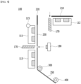
- Fig. 1 is a diagram showing a conventional electrode manufacturing device.
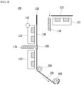
- Fig. 2 is a diagram showing a state where in the electrode manufacturing device of Fig. 1 , defective electrodes are separated and discarded, and normal electrodes are reconnected.
- the conventional electrode manufacturing device 10 includes an electrode suction unit 11, an electrode moving unit 15, and a cutting unit 17.
- the electrode suction unit 11 can suction an electrode 20 moved by the electrode moving unit 15.
- the electrode 20 may include a normal electrode 21 and a defective electrode 25.
- the conventional electrode manufacturing device 10 manually cuts between the normal electrode 21 and the defective electrode 25 via the cutting unit 17.
- the defective electrode 25 cut by the cutting unit 17 in Fig. 2(a) is manually wound around the winding unit 40 along the guide roll 30, and the space between the defective electrode 25 and the normal electrode 21 is manually cut.
- the normal electrode 21 manually cut in Fig. 2(b) manually attaches and reconnects the normal electrode 21 and a tape 29 cut by the cutting unit 17 of Fig. 2(a) .
- the conventional electrode manufacturing device 10 manually performs both the discarding and winding of the defective electrode 25 as shown in Fig. 2 , and also manually performs the reconnection between the normal electrodes 21, which causes a problem that equipment efficiency and productivity are deteriorated.
- an electrode manufacturing device that automatically separates the defective electrode and the normal electrode, and can automatically perform the disposal of the defective electrode and the reconnection of the normal electrode, unlike the conventional electrode manufacturing device 10.
- an electrode manufacturing device comprising: a first electrode suction unit and a second electrode suction unit that suction a first electrode, with the first electrode including a normal electrode and a defective electrode; a third electrode suction unit that suctions a second electrode; a rotating unit that is connected to an end of the first electrode suction unit and rotates the first electrode suction unit; a cutting unit that cuts between the normal electrode and the defective electrode; and a taping unit that is positioned apart from and facing the cutting unit, wherein, when the cutting operation of the cutting unit is completed, the rotating unit rotates so that the first electrode suction unit is arranged on the same plane as the second electrode suction unit or the third electrode suction unit.
- the first electrode suction unit, the second electrode suction unit, and the third electrode suction unit may respectively include a suction plate.
- the second electrode suction unit and the third electrode suction unit may be arranged separately in a direction perpendicular to each other.
- the rotating unit may be composed of a motor and a worm gear.
- the cutting unit may be composed of a rodless cylinder.
- the cutting unit includes a first cutting unit and a second cutting unit
- the taping unit includes a first taping unit and a second taping unit
- the first cutting unit and the first taping unit may be positioned between the first electrode suction unit and the second electrode suction unit
- the second cutting unit and the second taping unit may be positioned between the first electrode suction unit and the third electrode suction unit.
- the normal electrode includes a first normal electrode and a second normal electrode, and the defective electrode may be positioned between the first normal electrode and the second normal electrode.
- the first normal electrode may be positioned on the second electrode suction unit, and the first cutting unit cuts between the first normal electrode and the defective electrode.
- the first electrode suction unit may be rotated by the rotating unit and connected to the third electrode suction unit, and the defective electrode may be connected to the second electrode by the second taping unit.
- the second taping unit may attach a first adhesive sheet between the defective electrode and the second electrode.
- the electrode manufacturing device may further include a winding unit that winds at least a part of the connected defective electrode and the second electrode.
- a length wound by the winding unit may be equal to or greater than the length of the defective electrode.
- the second normal electrode is positioned in the first electrode suction unit by the winding unit, and the second cutting unit may cut between the second normal electrode and the defective electrode.
- the first electrode suction unit may be rotated by the rotating unit and connected to the second electrode suction unit, and the second normal electrode may be connected to the first normal electrode by the first taping unit.
- the first taping unit may attach a second adhesive sheet between the first normal electrode and the second normal electrode.
- Whether or not the cutting operation is completed may be determined based on the position of the cutting unit.
- the electrode manufacturing device further includes a detection unit, the detection unit determines whether or not a defective electrode is included in the first electrode, and suction operations of the first electrode suction unit and the second electrode suction unit may be performed based on the information acquired by the detection unit.
- a method for manufacturing an electrode which is performed by the above-mentioned electrode manufacturing device, the method comprising the steps of: cutting the first electrode positioned in the first electrode suction unit and the second electrode suction unit by the cutting unit, thus separating a normal electrode from a defective electrode; positioning the first electrode suction unit on the same plane as the third electrode suction unit by rotating the rotating unit, and connecting the defective electrode on the first electrode suction unit and the second electrode on the third electrode suction unit by the taping unit.
- an electrode for a secondary battery manufactured by the above-mentioned electrode manufacturing device.
- an electrode manufacturing device that can automatically separate and discard a normal electrode and a defective electrode, and automatically reconnect a normal electrode, thereby improving equipment efficiency and productivity.
- planar when referred to as “planar”, it means when a target portion is viewed from the upper side, and when referred to as “cross-sectional”, it means when a target portion is viewed from the side of a cross section cut vertically.
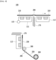
- Fig. 3 is a diagram showing an electrode manufacturing device according to an embodiment of the present disclosure.
- an electrode manufacturing device 100 includes a first electrode suction unit 111 and a second electrode suction unit 112 that suction a first electrode 200; a third electrode suction unit 113 that suctions a second electrode 250; a cutting unit 170; and a taping unit 190.
- the first electrode 200 may be a positive electrode or a negative electrode commonly used in the manufacture of an electrode. At this time, the structure, shape, constituent material, etc. of the positive electrode or negative electrode are not limited. Further, the second electrode 250 may be a discarded electrode. As an example, the second electrode 250 may be a discarded electrode corresponding to a defective electrode at the time of manufacturing the electrode.
- the first electrode suction unit 111, the second electrode suction unit 112, and the third electrode suction unit 113 may each include a suction plate.
- the surface of the suction plate is finely perforated, and a hood is installed in the lower part of the suction plate, and then a hose can be installed in the lower part of the hood.
- Suction can be performed via a hose using a ring blower.
- the present disclosure is not limited thereto, and any part capable of sucking the first electrode 200 or the second electrode 250 can be used without limitation.
- the first electrode suction unit 111 may have a rotating part 115 formed at one end of the first electrode suction unit 111. Also, the first electrode suction unit 111 may be rotated around the rotating unit 115 as an axis.
- the rotating unit 115 may be composed of a motor and a worm gear.
- the present disclosure is not limited thereto, and any part capable of rotating the first electrode suction unit 111 at a predetermined angle can be used without limitation.
- the first electrode suction unit 111 may be connected to the second electrode suction unit 112 or the third electrode suction unit 113 according to the rotation of the rotating unit 115.
- the first electrode suction unit 111 may be arranged on the same plane as the second electrode suction unit 112 or the third electrode suction unit 113 according to the rotation of the rotating unit 115.
- the first electrode suction unit 111 and the second electrode suction unit 112 can each allow the first electrode 200 to suction on the same plane.
- the first electrode suction unit 111 and the third electrode suction unit 113 can allow the first electrode 200 or the second electrode 250 to suction on the same plane, respectively.
- the first electrode suction unit 111 When the first electrode 200 is cut by a cutting unit 170, the first electrode suction unit 111 can be rotated by the rotating unit 115. More specifically, the first electrode suction unit 111 is connected to the second electrode suction unit 112 or the third electrode suction unit 113, but can be rotated by the rotating unit 115 when it is cut by the cutting unit 170. At this time, the first electrode suction unit 111 may be connected to the second electrode suction unit 112 or the third electrode suction unit 113 that have not been connected by the rotating unit 115.
- the second electrode suction unit 112 and the third electrode suction unit 113 may be separated from each other with respect to the first electrode suction unit 111.
- the second electrode suction unit 112 and the third electrode suction unit 113 may be separated from each other by the same distance with respect to the first electrode suction unit 111. The distance may be equal to or greater than the length of the first electrode suction unit 111.
- the cutting unit 170 can cut the first electrode 200.
- the first electrode 200 includes a normal electrode and a defective electrode, so that the cutting unit 170 can cut between the normal electrode and the defective electrode in the first electrode 200.
- the cutting unit 170 may cut a boundary line between the normal electrode and the defective electrode.
- the cutting unit 170 cuts between the normal electrode and the defective electrode, and may cut a portion adjacent to the normal electrode based on a boundary line between the normal electrode and the defective electrode.
- the cutting unit 170 may be composed of a rodless cylinder.
- the cutting unit 170 may be composed of a saw type knife, but can be driven by a cylinder.
- the present disclosure is not limited thereto, and any part capable of cutting the first electrode 200 can be used without limitation.
- the taping part 190 can attach any one of a metal foil, a general tape, an insulating tape, and a conductive tape to the first electrode 200 and/or the second electrode 250 as an adhesive sheet. Moreover, the taping part 190 may coat the first electrode 200 and/or the second electrode 250 with an adhesive composition such as an adhesive binder or a conductive binder. Thereby, the first electrode 200 and/or the second electrode 250 may be connected to each other without interfering with the current flowing through the first electrode 200 and the second electrode 250.
- the present disclosure is not limited thereto, and various types of materials can be adhered or coated.
- the cutting unit 170 cuts the first electrode 200, and the taping unit 190 may be positioned separately in a direction facing the cutting unit 170.
- the cutting part 170 is positioned in the lower part of the first electrode 200 with respect to the first electrode 200, and the taping unit 190 may be positioned in the upper part of the first electrode 200.
- the cutting unit 170 is positioned in the upper part of the first electrode 200 with respect to the first electrode 200, and the taping unit 190 may be positioned in the lower part of the first electrode 200.
- the cutting unit 170 includes a first cutting unit and a second cutting unit
- the taping part 190 includes a first taping unit and a second taping unit.
- the first cutting unit and the first taping unit may be positioned between the first electrode suction unit 111 and the second electrode suction unit 112.
- the first electrode 200 positioned on the first electrode suction unit 111 and the second electrode suction unit 112 may be cut and reconnected by the first cutting unit and the first taping unit.
- the second cutting unit and the second taping unit may be positioned between the first electrode suction unit 111 and the third electrode suction unit 113.
- the first electrode 200 and/or the second electrode 250 positioned on the first electrode suction unit 111 and the third electrode suction unit 113 can be cut and reconnected by the second cutting unit and the second taping unit.
- the electrode manufacturing device 100 may further include a guide roll 300 that guides the second electrode 250 positioned on the third electrode suction unit 113, and a winding unit 400 that winds the second electrode 250.
- the guide roll 300 may guide a path in which the second electrode 250 may be wound by the winding unit 400.
- the guide roll 300 may be positioned adjacent to the end of the third electrode suction unit 113.
- the winding unit 400 can wind the second electrode 250 by a predetermined length.
- the winding unit 400 can wind the second electrode 250 by the length of the defective electrode included in the first electrode 200.
- Figs. 4 to 9 are diagrams showing that in the electrode manufacturing device of Fig. 3 , defective electrodes are separated and discarded, and normal electrodes are reconnected.
- the electrode manufacturing device 100 includes a separate control unit (not shown), and thus can control driving of a first electrode suction unit 111 and a second electrode suction unit 112; a third electrode suction unit 113; a cutting unit 170; and a taping unit 190.
- the control unit may process information for determining whether or not the first electrode 200 is defective, and can control driving of the first electrode suction unit 111 and the second electrode suction unit 112; the third electrode suction unit 113; the cutting unit 170; and the taping unit 190, via the information on whether or not the first electrode 200 is defective.
- whether or not the first electrode 200 is defective may be information acquired by a separate detection unit (not shown).
- a detection unit (not shown) can determine whether or not the first electrode 200 is defective.
- a detection unit (not shown) may determine whether or not the first electrode 200 is defective based on a coating defect or the like. Alternatively, the detection unit (not shown) may determine the presence or absence of defects via a tag previously displayed on the first electrode 200.
- the detection unit may transmit information for determining whether or not the first electrode 200 is defective to a control unit (not shown), and the control unit (not shown) may control the operation of each component based on information transmitted from the detection unit (not shown).
- an example of the detection unit (not shown) that can be used in the electrode manufacturing device 100 of the present embodiment may include, but is not limited to, a vision for determining the presence or absence of defects, based on an image.
- the detection units (not shown) used in the present embodiment may be formed in plural numbers, and in addition to confirming whether or not the first electrode 200 is defective, it may be arranged at a position necessary for confirming whether or not to permit the operation of each component.
- the detection unit (not shown) may transmit information acquired at the corresponding position to the control unit (not shown), and the control unit (not shown) may instruct the operation of each component based on this.
- the control unit may include one or more selected from CPU (Central Processing Unit), RAM (Random Access Memory), GPU (Graphic Processing Unit), one or more microprocessors, and electronic components capable of processing input data according to other predetermined logic.
- the control unit develops an electrode manufacturing process capable of being performing from an electrode manufacturing device described later on the RAM, and can perform various processes such as controlling the driving of the first electrode suction unit 111 and the second electrode suction unit 112; the third electrode suction unit 113; the cutting unit 170; and the taping unit 190 according to the developed program.
- the first electrode 200 may include a normal electrode 210 and 220 and a defective electrode 230.
- the normal electrode may include a first normal electrode 210 and a second normal electrode 220, and the defective electrode 230 may be positioned between the first normal electrode 210 and the second normal electrode 220.
- the first electrode suction unit 111 may suction the first electrode 200, the first normal electrode 210, the defective electrode 230, and the second normal electrode 220.
- the second electrode suction unit 112 may suction the first normal electrode 210.
- the first normal electrode 210 is positioned on the second electrode suction unit 112, and the cutting unit 170 can cut between the first normal electrode 210 and the defective electrode 230.
- the cutting unit 170 may be described as the above-mentioned first cutting unit.
- the first electrode suction unit 111 may be rotated by the rotating unit 115. Thereby, the electrode manufacturing device 100 according to the present embodiment can automatically separate the defective electrode 230 included in the first electrode 200 from the first normal electrode 210.
- the detection unit may confirm that the defective electrode 230 is positioned on the first electrode suction unit 111 or that the first normal electrode 210 is positioned on the third electrode suction unit 113.
- the operation of each configuration can be controlled by a control unit (not shown), and the control unit (not shown) may use information transmitted from the detection unit (not shown) or each component.
- the first electrode 200 includes the defective electrode 230, and when it is confirmed that the defective electrode 230 is positioned on the first electrode suction unit 111 or the first normal electrode 210 is positioned on the third electrode suction unit 113, the first electrode suction unit 111 and the second electrode suction unit 112 can be driven by the control unit.
- control unit may instruct the operation of the other configuration after completion of the operation of the specific configuration is conformed. Specifically, when it is confirmed whether the control unit (not shown) holds the first electrode 200 by the first electrode suction unit 111 and the second electrode suction unit 112, it can instruct an operation to the cutting unit 170 so as to separate the first normal electrode 210 and the defective electrode 230. Further, after the cutting operation of the cutting unit 170 is completed, the control unit (not shown) may cause the rotating unit 115 to rotate the first electrode suction unit 111 in a direction in which the third electrode suction unit 113 is located. Here, the completion of the cutting operation of the cutting unit 170 can be confirmed through the position of the cutting unit 170.
- the cutting unit 170 can be determined whether the cutting unit 170 has deviated from the device driving space in which the first electrode 200 is located, or, as another example, whether the cutting unit 170 has returned to its original position.
- the position of the cutting unit 170 may be detected via a detection unit (not shown).
- the first electrode suction unit 111 may be rotated by the rotating unit 115 and arranged on the same plane as the third electrode suction unit 113. Thereby, the first electrode suction unit 111 may be connected to the third electrode suction unit 113. Further, the taping unit 190 may connect the defective electrode 230 positioned on the first electrode suction unit 111 and the second electrode 250 positioned on the third electrode suction unit 113. Here, the taping unit 190 may be described as the above-mentioned second taping unit. Further, the taping unit 190 can attach an adhesive sheet 290 between the defective electrode 230 positioned on the first electrode suction unit 111 and the second electrode 250 positioned on the third electrode suction unit 113. Thereby, in the electrode manufacturing device 100 according to the present embodiment, the defective electrode 230 included in the first electrode 200 can be automatically connected to the second electrode 250.
- the third electrode suction unit 113 may be in a state of holding the second electrode 250 in advance.
- the first electrode suction unit 111 may also be in a state of holding the first electrode 200, that is, the defective electrode 230.
- the operation of the taping unit 190 may be performed after the correspondence between the first electrode suction unit 111 and the third electrode suction unit 113 is confirmed.
- the correspondence between the first electrode suction unit 111 and the third electrode suction unit 113 can be determined by whether or not the rotating unit 115 is stopped.
- a separate detection unit not shown positioned around the first electrode suction unit 111 and the third electrode suction unit 113 moved by the rotating unit 115, it can be determined whether the first electrode suction unit 111 and the third electrode suction unit 113 are positioned on the same plane.
- the operation of each configuration may be performed by the control unit, and more specifically, the control unit can instruct the operation of the taping unit 190 after the correspondence between the first electrode suction unit 111 and the third electrode suction unit 113 is confirmed.
- the adhesive sheet 290 may be attached between the defective electrode 230 positioned on the first electrode suction unit 111 and the second electrode 250 positioned on the third electrode suction unit 113. Further, the winding unit 400 can wind the defective electrode 230 and the second electrode 250 to which the adhesive sheet 290 is attached along a guide roll 300 by a predetermined length. The winding unit 400 may wind at least a part of the connected defective electrode 230 and the second electrode 250. As an example, the winding unit 400 can wind the defective electrode 230 and the second electrode 250 to which the adhesive sheet 290 is attached so as to be equal to the length of the defective electrode 230 or to be longer than the length of the defective electrode 230.
- the electrode manufacturing device 100 can allow the defective electrode 230 positioned on the first electrode suction unit 111 to move onto the third electrode suction unit 113, and a second normal electrode 220 may be sucked into the second electrode suction unit 112.
- the suction operations of the first electrode suction unit 111 and the third electrode suction unit 113 may be stopped in the same manner as or earlier than the winding operation of the winding unit 400.
- the operation of the winding unit 400 or a stop of the suction operations of the first electrode suction unit 111 and the third electrode suction unit 113 may be performed after the operation of the taping unit 190 is completed.
- the completion of the operation of the taping part 190 may be determined according to the position of the taping part 190 or whether the adhesive sheet 290 is attached to the defective electrode 230 and the second electrode 250.
- the position of the taping unit 190 or the presence or absence of adhesion of the adhesive sheet 290 may be confirmed by a detection unit (not shown).
- the winding length by the winding unit 400 may be determined based on information collected by the detection unit (not shown). For example, the detection unit (not shown) may confirm the size of the defective electrode 230, and based on this, the operation time of the winding unit 400 can be adjusted. As another example, the detection unit (not shown) determines whether the defective electrode 230 is completely moved so as to be positioned on the third electrode suction unit 113, or whether the second normal electrode 220 is completely moved so as to be completely located on the first electrode suction unit 111. Based on this, the operation of the winding unit 400 may be stopped.
- each configuration may be instructed by a control unit (not shown).
- the control unit can instruct the operation of the winding unit 400 or the suction stop of the first electrode suction unit 111 and the third electrode suction unit 113. Further, the control unit (not shown) can control the operation time of the winding unit 400 based on information acquired from the detection unit (not shown) or each configuration.
- the second normal electrode 220 is positioned on the first electrode suction unit 111, and the cutting portion 170 can cut between the second normal electrode 220 and the defective electrode 230.
- the first electrode suction unit 111 may be rotated by the rotating unit 115.
- the second normal electrode 220 cut by the cutting unit 170 may be positioned on the first electrode suction unit 111.
- the cutting unit 170 may be described as the above-mentioned second cutting unit.
- the electrode manufacturing device 100 may automatically separate the second normal electrode 220 and the defective electrode 230 included in the first electrode 200.
- the first electrode suction unit 111 and the third electrode suction unit 113 can be driven.
- the position of the second normal electrode 220 or the defective electrode 230 may be confirmed by a detection unit (not shown).
- the first electrode suction unit 111 and the third electrode suction unit 113 may be driven based on the winding operation stop of the winding unit 400.
- the cutting unit 170 can separate the second normal electrode 220 and the defective electrode 230.
- the rotating unit 115 may rotate so that the first electrode suction unit 111 moves in a direction in which the second electrode suction unit 112 is located.
- the completion of the cutting operation of the cutting unit 170 can be confirmed via the position of the cutting unit 170.
- the operation of each configuration may be performed by a control unit (not shown), and the control unit (not shown) may use information acquired by the detection unit (not shown) or information transmitted from each component in controlling the operation of each component.
- the description of Fig. 4 can be referred to, and thus a detailed description thereof will be omitted.
- the first electrode suction unit 111 may be rotated by the rotating unit 115 and rearranged on the same plane as the second electrode suction unit 112. Thereby, the first electrode suction unit 111 may be reconnected with the second electrode suction unit 112. Further, the taping part 190 may be connected to the second normal electrode 220 positioned on the first electrode suction part 111 and the first normal electrode 210 positioned on the second electrode suction part 112.
- the taping unit 190 may be described as the above-mentioned first taping part.
- the taping unit 190 can attach an adhesive sheet 290 between the second normal electrode 220 positioned on the first electrode suction part 111 and the first normal electrode 210 positioned on the second electrode suction part 112.
- the electrode manufacturing device 100 may automatically connect the first normal electrode 210 and the second normal electrode 220 included in the first electrode 200. That is, the defective electrode 230 included in the first electrode 200 may be automatically removed.
- the second electrode suction unit 112 may be in a state of holding the first normal electrode 210.
- the first electrode suction unit 111 may also be in a state of holding the second normal electrode 220.
- the operation of the taping unit 190 may be performed after the correspondence between the first electrode suction unit 111 and the second electrode suction unit 112 is confirmed.
- the descriptions of Figs. 5 and 6 may be referred to, and thus detailed description thereof will be omitted.
- the electrode manufacturing device 100 can automatically reconnect the normal electrodes 210 and 220 while automatically discharging the defective electrode 230, thereby improving equipment efficiency and productivity as compared with the conventional case.
- the electrode manufacturing method S100 may include a step S110 of cutting the first electrode 200 positioned between the first electrode suction unit 111 and a second electrode suction unit 112 by a cutting unit 170, a step S120 of positioning on the same plane as the third electrode suction unit 113 by rotating the first electrode suction unit 111, a step S130 of connecting the first electrode 200 on the first electrode suction unit 111 and the second electrode 250 on the third electrode suction unit 113 by the taping unit 190, a step S 140 of winding at least a part of the first electrode 200 and the second electrode 250 to which the winding unit 400 is connected, a step S150 of cutting the first electrode 200 positioned between the first electrode suction unit 111 and the third electrode suction unit 113 by the cutting unit 170, a step S160 of positioning on the same plane as the second electrode suction unit 112 by rotating the first electrode suction unit 111, and a step S170 of connecting the first electrode 200 on the first electrode suction part 111 and the first electrode 200
- the electrode manufacturing method S100 may further include the step of confirming whether the first electrode 200 includes the defective electrode 230 before the step S110 of cutting the first electrode 200. At this time, the presence or absence of the defective electrode 230 can be confirmed by a detection unit (not shown).
- the step S110 of cutting the first electrode 200 can be performed depending on whether the first electrode 200 includes the defective electrode 230.
- the above-mentioned step S110 can be embodied through a step of positioning the defective electrode 230 on the first electrode suction unit 111 and the first normal electrode 210 on the second electrode suction unit 112, a step of holding the defective electrode 230 by the first electrode suction unit 111 and holding the first normal electrode 210 by the second electrode suction unit 112, and a step of separating the defective electrode 230 and the first normal electrode 210 by the cutting unit 170.
- the cutting unit 170 may be a first cutting unit. Detailed description of each step may be specifically given with reference to Fig. 4 and a description thereof, and thus a detailed description will be omitted.
- the step S120 of positioning the first electrode suction unit 111 and the third electrode suction unit 113 on the same plane by rotating the first electrode suction unit 111 can be performed after the completion of the operation of the cutting unit 170 is confirmed.
- the step S130 of connecting the first electrode 200 on the first electrode suction unit 111 and the second electrode 250 on the third electrode suction unit 113 by the taping unit 190 can be performed after the correspondence between the first electrode suction unit 111 and the third electrode suction unit 113 is confirmed.
- the taping unit 190 can connect the defective electrode 230 and the second electrode 250, and the taping unit 190 may be a second taping unit.
- the step S140 of winding at least a part of the first electrode 200 and the second electrode 250 to which the winding unit 400 is connected can be performed after the operation of the taping unit 190 is completed.
- the above-mentioned step S140 can be embodied through a step of stopping the suction of the first electrode suction unit 111 and the third electrode suction unit 113, a step of winding at least a part of the first electrode 200 and the second electrode 250 to which the winding unit 400 is connected, and a step of stopping the winding operation by the winding unit 400.
- Detailed description of each step may be specifically given with reference to Fig. 6 and a description thereof, and thus a detailed description will be omitted.
- the step S150 of cutting the first electrode 200 positioned between the first electrode suction unit 111 and the third electrode suction unit 113 by the cutting unit 170 can be performed after the winding operation of the winding portion 400 is stopped.
- the above-mentioned step S150 may be embodied through a step of positioning the second normal electrode 220 on the first electrode suction unit 111 and positioning the defective electrode 230 on the third electrode suction part 113, a step of holding the second normal electrode 220 by the first electrode suction unit 111 and holding the defective electrode 230 by the third electrode suction unit 113, and a step of separating the defective electrode 230 and the second normal electrode 220 by the cutting unit 170.
- the cutting unit 170 may be a second cutting unit. Detailed description of each step may be given in detail with reference to Fig. 7 and a description thereof, and thus a detailed description will be omitted.
- the step S160 of positioning the first electrode suction unit 111 on the same plane as the second electrode suction unit 112 by rotating the first electrode suction unit 111 can be performed after completion of the operation of the cutting unit 170 is confirmed.
- the step S170 of connecting the first electrode 200 on the first electrode suction part 111 and the first electrode 200 on the second electrode suction part 112 by the taping unit 190 can be performed after the correspondence between the first electrode suction unit 111 and the second electrode suction unit 112 is confirmed.
- the taping unit 190 may connect the first normal electrode 210 and the second normal electrode 220, and the taping unit 190 may be a first taping unit.
- the electrode for a secondary battery according to another embodiment of the present disclosure may be manufactured by the above-mentioned electrode manufacturing device.
- the electrode for a secondary battery manufactured by the electrode manufacturing device described above may be applied to various secondary batteries.
- Such a secondary battery can be applied to a cylindrical battery having an electrode assembly mounted in a cylindrical metal can, a prismatic battery having an electrode assembly mounted in a prismatic metal can, and a pouch type battery having an electrode assembly mounted in a pouch-shaped case made of a laminated aluminum sheet, but the present disclosure is not limited thereto and is applicable to various secondary batteries in which the electrode for secondary batteries can be used, which also falls within the scope of the present disclosure.
Landscapes
- Engineering & Computer Science (AREA)
- Chemical & Material Sciences (AREA)
- Manufacturing & Machinery (AREA)
- Chemical Kinetics & Catalysis (AREA)
- Electrochemistry (AREA)
- General Chemical & Material Sciences (AREA)
- Materials Engineering (AREA)
- Life Sciences & Earth Sciences (AREA)
- Forests & Forestry (AREA)
- Mechanical Engineering (AREA)
- Secondary Cells (AREA)
- Battery Electrode And Active Subsutance (AREA)
Abstract
Description
- This application claims the benefit of
Korean Patent Application No. 10-2021-0003822 filed on January 12, 2021 Korean Patent Application No. 10-2022-0002295 filed on January 6, 2022 - The present disclosure relates to an electrode manufacturing device and an electrode manufacturing method using the same, and more particularly, to an electrode manufacturing device that automatically separates and discards a normal electrode and a defective electrode, and automatically reconnects a normal electrode, thereby improving equipment efficiency and productivity, and an electrode manufacturing method using the same.
- Along with the increase of technology development and demands for mobile devices, the demand for batteries as energy sources is increasing rapidly. In particular, a secondary battery has attracted considerable attention as an energy source for power-driven devices, such as an electric bicycle, an electric vehicle, and a hybrid electric vehicle, as well as an energy source for mobile devices, such as a mobile phone, a digital camera, a laptop computer and a wearable device.
- The secondary battery may be classified based on the shape of a battery case into a cylindrical battery having an electrode assembly mounted in a cylindrical metal can, a prismatic battery having an electrode assembly mounted in a prismatic metal can, and a pouch type battery having an electrode assembly mounted in a pouch-shaped case made of a laminated aluminum sheet.
- Further, the secondary battery can be formed by inserting an electrode assembly composed of a positive electrode, a negative electrode, and a separator into a case, and then sealing the case. The electrode assembly can be formed by interposing a separator between the positive electrode and the negative electrode, and winding the electrode in a j elly-roll type many times or laminating it in a plurality of layers.
- Meanwhile, in recent years, secondary batteries perform a roll-to-roll process when manufacturing raw materials for electrodes such as a positive electrode, a negative electrode and a separator. However, if the raw materials contain defects during the operation of the roll-to-roll process, it is necessary to discard the defective parts at the beginning of the process and then reconnect the normal parts.
-
Fig. 1 is a diagram showing a conventional electrode manufacturing device.Fig. 2 is a diagram showing a state where in the electrode manufacturing device ofFig. 1 , defective electrodes are separated and discarded, and normal electrodes are reconnected. - Referring to
Fig. 1 , the conventionalelectrode manufacturing device 10 includes anelectrode suction unit 11, anelectrode moving unit 15, and acutting unit 17. Here, theelectrode suction unit 11 can suction anelectrode 20 moved by theelectrode moving unit 15. - Referring to
Fig. 2(a) , theelectrode 20 may include anormal electrode 21 and adefective electrode 25. Here, when thedefective electrode 25 passes through theelectrode suction unit 11, the conventionalelectrode manufacturing device 10 manually cuts between thenormal electrode 21 and thedefective electrode 25 via thecutting unit 17. Referring toFig. 2(b) , thedefective electrode 25 cut by thecutting unit 17 inFig. 2(a) is manually wound around thewinding unit 40 along theguide roll 30, and the space between thedefective electrode 25 and thenormal electrode 21 is manually cut. Referring toFig. 2(c) , thenormal electrode 21 manually cut inFig. 2(b) manually attaches and reconnects thenormal electrode 21 and atape 29 cut by thecutting unit 17 ofFig. 2(a) . - However, the conventional
electrode manufacturing device 10 manually performs both the discarding and winding of thedefective electrode 25 as shown inFig. 2 , and also manually performs the reconnection between thenormal electrodes 21, which causes a problem that equipment efficiency and productivity are deteriorated. Thereby, there is a growing need to develop an electrode manufacturing device that automatically separates the defective electrode and the normal electrode, and can automatically perform the disposal of the defective electrode and the reconnection of the normal electrode, unlike the conventionalelectrode manufacturing device 10. - It is an object of the present disclosure to provide an electrode manufacturing device that automatically separates and discards a normal electrode and a defective electrode, and automatically reconnects a normal electrode, thereby improving equipment efficiency and productivity, and an electrode manufacturing method using the same.
- The objects of the present disclosure are not limited to the aforementioned objects, and other objects which are not described herein should be clearly understood by those skilled in the art from the following detailed description and the accompanying drawings.
- According to one embodiment of the present disclosure, there is provided an electrode manufacturing device comprising: a first electrode suction unit and a second electrode suction unit that suction a first electrode, with the first electrode including a normal electrode and a defective electrode; a third electrode suction unit that suctions a second electrode; a rotating unit that is connected to an end of the first electrode suction unit and rotates the first electrode suction unit; a cutting unit that cuts between the normal electrode and the defective electrode; and a taping unit that is positioned apart from and facing the cutting unit, wherein, when the cutting operation of the cutting unit is completed, the rotating unit rotates so that the first electrode suction unit is arranged on the same plane as the second electrode suction unit or the third electrode suction unit.
- The first electrode suction unit, the second electrode suction unit, and the third electrode suction unit may respectively include a suction plate.
- The second electrode suction unit and the third electrode suction unit may be arranged separately in a direction perpendicular to each other.
- The rotating unit may be composed of a motor and a worm gear.
- The cutting unit may be composed of a rodless cylinder.
- The cutting unit includes a first cutting unit and a second cutting unit, and the taping unit includes a first taping unit and a second taping unit, the first cutting unit and the first taping unit may be positioned between the first electrode suction unit and the second electrode suction unit, and the second cutting unit and the second taping unit may be positioned between the first electrode suction unit and the third electrode suction unit.
- The normal electrode includes a first normal electrode and a second normal electrode, and the defective electrode may be positioned between the first normal electrode and the second normal electrode.
- The first normal electrode may be positioned on the second electrode suction unit, and the first cutting unit cuts between the first normal electrode and the defective electrode.
- The first electrode suction unit may be rotated by the rotating unit and connected to the third electrode suction unit, and the defective electrode may be connected to the second electrode by the second taping unit.
- The second taping unit may attach a first adhesive sheet between the defective electrode and the second electrode.
- The electrode manufacturing device may further include a winding unit that winds at least a part of the connected defective electrode and the second electrode.
- A length wound by the winding unit may be equal to or greater than the length of the defective electrode.
- The second normal electrode is positioned in the first electrode suction unit by the winding unit, and the second cutting unit may cut between the second normal electrode and the defective electrode.
- The first electrode suction unit may be rotated by the rotating unit and connected to the second electrode suction unit, and the second normal electrode may be connected to the first normal electrode by the first taping unit.
- The first taping unit may attach a second adhesive sheet between the first normal electrode and the second normal electrode.
- Whether or not the cutting operation is completed may be determined based on the position of the cutting unit.
- The electrode manufacturing device further includes a detection unit, the detection unit determines whether or not a defective electrode is included in the first electrode, and suction operations of the first electrode suction unit and the second electrode suction unit may be performed based on the information acquired by the detection unit.
- According to another embodiment of the present disclosure, there is provided a method for manufacturing an electrode, which is performed by the above-mentioned electrode manufacturing device, the method comprising the steps of: cutting the first electrode positioned in the first electrode suction unit and the second electrode suction unit by the cutting unit, thus separating a normal electrode from a defective electrode; positioning the first electrode suction unit on the same plane as the third electrode suction unit by rotating the rotating unit, and connecting the defective electrode on the first electrode suction unit and the second electrode on the third electrode suction unit by the taping unit.
- According to yet another embodiment of the present disclosure, there is provided an electrode for a secondary battery manufactured by the above-mentioned electrode manufacturing device.
- According to embodiments of the present disclosure, there is provided an electrode manufacturing device that can automatically separate and discard a normal electrode and a defective electrode, and automatically reconnect a normal electrode, thereby improving equipment efficiency and productivity.
- The effects of the present disclosure are not limited to the effects mentioned above and additional other effects not described above will be clearly understood from the description of the appended claims by those skilled in the art.
-
-
Fig. 1 is a diagram showing a conventional electrode manufacturing device; -
Fig. 2 is a diagram showing a state where in the electrode manufacturing device ofFig. 1 , defective electrodes are separated and discarded, and normal electrodes are reconnected; -
Fig. 3 is a diagram showing an electrode manufacturing device according to an embodiment of the present disclosure; and -
Figs. 4 to 9 are diagrams showing that in the electrode manufacturing device ofFig. 3 , defective electrodes are separated and discarded, and normal electrodes are reconnected. - Hereinafter, various embodiments of the present disclosure will be described in detail with reference to the accompanying drawings so that those skilled in the art can easily carry out them. The present disclosure may be modified in various different ways, and is not limited to the embodiments set forth herein.
- A description of parts not related to the description will be omitted herein for clarity, and like reference numerals designate like elements throughout the description.
- Further, in the drawings, the size and thickness of each element are arbitrarily illustrated for convenience of description, and the present disclosure is not necessarily limited to those illustrated in the drawings. In the drawings, the thickness of layers, regions, etc. are exaggerated for clarity. In the drawings, for convenience of description, the thicknesses of some layers and regions are exaggerated.
- Further, throughout the description, when a portion is referred to as "including" a certain component, it means that the portion can further include other components, without excluding the other components, unless otherwise stated.
- Further, throughout the description, when referred to as "planar", it means when a target portion is viewed from the upper side, and when referred to as "cross-sectional", it means when a target portion is viewed from the side of a cross section cut vertically.
- Now, the electrode manufacturing device according to an embodiment of the present disclosure will be described.
-
Fig. 3 is a diagram showing an electrode manufacturing device according to an embodiment of the present disclosure. - Referring to
Fig. 3 , anelectrode manufacturing device 100 according to the present embodiment includes a firstelectrode suction unit 111 and a secondelectrode suction unit 112 that suction afirst electrode 200; a thirdelectrode suction unit 113 that suctions asecond electrode 250; acutting unit 170; and ataping unit 190. - The
first electrode 200 may be a positive electrode or a negative electrode commonly used in the manufacture of an electrode. At this time, the structure, shape, constituent material, etc. of the positive electrode or negative electrode are not limited. Further, thesecond electrode 250 may be a discarded electrode. As an example, thesecond electrode 250 may be a discarded electrode corresponding to a defective electrode at the time of manufacturing the electrode. - More specifically, the first
electrode suction unit 111, the secondelectrode suction unit 112, and the thirdelectrode suction unit 113 may each include a suction plate. As an example, in the firstelectrode suction unit 111, the secondelectrode suction unit 112, and the thirdelectrode suction unit 113, the surface of the suction plate is finely perforated, and a hood is installed in the lower part of the suction plate, and then a hose can be installed in the lower part of the hood. Suction can be performed via a hose using a ring blower. However, the present disclosure is not limited thereto, and any part capable of sucking thefirst electrode 200 or thesecond electrode 250 can be used without limitation. - The first
electrode suction unit 111 may have arotating part 115 formed at one end of the firstelectrode suction unit 111. Also, the firstelectrode suction unit 111 may be rotated around therotating unit 115 as an axis. - More specifically, the
rotating unit 115 may be composed of a motor and a worm gear. However, the present disclosure is not limited thereto, and any part capable of rotating the firstelectrode suction unit 111 at a predetermined angle can be used without limitation. - Further, the first
electrode suction unit 111 may be connected to the secondelectrode suction unit 112 or the thirdelectrode suction unit 113 according to the rotation of therotating unit 115. In other words, the firstelectrode suction unit 111 may be arranged on the same plane as the secondelectrode suction unit 112 or the thirdelectrode suction unit 113 according to the rotation of therotating unit 115. Thereby, the firstelectrode suction unit 111 and the secondelectrode suction unit 112 can each allow thefirst electrode 200 to suction on the same plane. Further, the firstelectrode suction unit 111 and the thirdelectrode suction unit 113 can allow thefirst electrode 200 or thesecond electrode 250 to suction on the same plane, respectively. - When the
first electrode 200 is cut by acutting unit 170, the firstelectrode suction unit 111 can be rotated by therotating unit 115. More specifically, the firstelectrode suction unit 111 is connected to the secondelectrode suction unit 112 or the thirdelectrode suction unit 113, but can be rotated by therotating unit 115 when it is cut by thecutting unit 170. At this time, the firstelectrode suction unit 111 may be connected to the secondelectrode suction unit 112 or the thirdelectrode suction unit 113 that have not been connected by therotating unit 115. - Further, the second
electrode suction unit 112 and the thirdelectrode suction unit 113 may be separated from each other with respect to the firstelectrode suction unit 111. As an example, the secondelectrode suction unit 112 and the thirdelectrode suction unit 113 may be separated from each other by the same distance with respect to the firstelectrode suction unit 111. The distance may be equal to or greater than the length of the firstelectrode suction unit 111. - Further, the second
electrode suction unit 112 and the thirdelectrode suction unit 113 may be arranged separately from each other in a direction having an angle of 90 degrees to 180 degrees with respect to the firstelectrode suction part 111. As an example, the secondelectrode suction unit 112 and the thirdelectrode suction unit 113 may be arranged separately in a direction perpendicular to each other. - Further, the
cutting unit 170 can cut thefirst electrode 200. Here, thefirst electrode 200 includes a normal electrode and a defective electrode, so that thecutting unit 170 can cut between the normal electrode and the defective electrode in thefirst electrode 200. As an example, thecutting unit 170 may cut a boundary line between the normal electrode and the defective electrode. Alternatively, thecutting unit 170 cuts between the normal electrode and the defective electrode, and may cut a portion adjacent to the normal electrode based on a boundary line between the normal electrode and the defective electrode. - More specifically, the
cutting unit 170 may be composed of a rodless cylinder. As another example, thecutting unit 170 may be composed of a saw type knife, but can be driven by a cylinder. However, the present disclosure is not limited thereto, and any part capable of cutting thefirst electrode 200 can be used without limitation. - Further, the taping
part 190 can attach any one of a metal foil, a general tape, an insulating tape, and a conductive tape to thefirst electrode 200 and/or thesecond electrode 250 as an adhesive sheet. Moreover, the tapingpart 190 may coat thefirst electrode 200 and/or thesecond electrode 250 with an adhesive composition such as an adhesive binder or a conductive binder. Thereby, thefirst electrode 200 and/or thesecond electrode 250 may be connected to each other without interfering with the current flowing through thefirst electrode 200 and thesecond electrode 250. However, the present disclosure is not limited thereto, and various types of materials can be adhered or coated. - Further, the
cutting unit 170 cuts thefirst electrode 200, and thetaping unit 190 may be positioned separately in a direction facing thecutting unit 170. As an example, the cuttingpart 170 is positioned in the lower part of thefirst electrode 200 with respect to thefirst electrode 200, and thetaping unit 190 may be positioned in the upper part of thefirst electrode 200. Conversely, thecutting unit 170 is positioned in the upper part of thefirst electrode 200 with respect to thefirst electrode 200, and thetaping unit 190 may be positioned in the lower part of thefirst electrode 200. - The
cutting unit 170 includes a first cutting unit and a second cutting unit, and thetaping part 190 includes a first taping unit and a second taping unit. Here, the first cutting unit and the first taping unit may be positioned between the firstelectrode suction unit 111 and the secondelectrode suction unit 112. Thereby, thefirst electrode 200 positioned on the firstelectrode suction unit 111 and the secondelectrode suction unit 112 may be cut and reconnected by the first cutting unit and the first taping unit. - Further, the second cutting unit and the second taping unit may be positioned between the first
electrode suction unit 111 and the thirdelectrode suction unit 113. Thereby, thefirst electrode 200 and/or thesecond electrode 250 positioned on the firstelectrode suction unit 111 and the thirdelectrode suction unit 113 can be cut and reconnected by the second cutting unit and the second taping unit. - Referring to
Fig. 3 , theelectrode manufacturing device 100 according to the present embodiment may further include aguide roll 300 that guides thesecond electrode 250 positioned on the thirdelectrode suction unit 113, and a windingunit 400 that winds thesecond electrode 250. - More specifically, the
guide roll 300 may guide a path in which thesecond electrode 250 may be wound by the windingunit 400. Here, theguide roll 300 may be positioned adjacent to the end of the thirdelectrode suction unit 113. Further, the windingunit 400 can wind thesecond electrode 250 by a predetermined length. As an example, the windingunit 400 can wind thesecond electrode 250 by the length of the defective electrode included in thefirst electrode 200. -
Figs. 4 to 9 are diagrams showing that in the electrode manufacturing device ofFig. 3 , defective electrodes are separated and discarded, and normal electrodes are reconnected. - Referring to
Figs. 3 and4 to 9 , an electrode manufacturing process of separating and discarding the defective electrode included in thefirst electrode 200 and reconnecting the normal electrode through theelectrode manufacturing device 100 according to the present embodiment will be described. - Here, the
electrode manufacturing device 100 according to the present embodiment includes a separate control unit (not shown), and thus can control driving of a firstelectrode suction unit 111 and a secondelectrode suction unit 112; a thirdelectrode suction unit 113; acutting unit 170; and ataping unit 190. - The control unit (not shown) may process information for determining whether or not the
first electrode 200 is defective, and can control driving of the firstelectrode suction unit 111 and the secondelectrode suction unit 112; the thirdelectrode suction unit 113; thecutting unit 170; and thetaping unit 190, via the information on whether or not thefirst electrode 200 is defective. - Here, whether or not the
first electrode 200 is defective may be information acquired by a separate detection unit (not shown). A detection unit (not shown) can determine whether or not thefirst electrode 200 is defective. A detection unit (not shown) may determine whether or not thefirst electrode 200 is defective based on a coating defect or the like. Alternatively, the detection unit (not shown) may determine the presence or absence of defects via a tag previously displayed on thefirst electrode 200. The detection unit may transmit information for determining whether or not thefirst electrode 200 is defective to a control unit (not shown), and the control unit (not shown) may control the operation of each component based on information transmitted from the detection unit (not shown). Meanwhile, an example of the detection unit (not shown) that can be used in theelectrode manufacturing device 100 of the present embodiment may include, but is not limited to, a vision for determining the presence or absence of defects, based on an image. - Further, the detection units (not shown) used in the present embodiment may be formed in plural numbers, and in addition to confirming whether or not the
first electrode 200 is defective, it may be arranged at a position necessary for confirming whether or not to permit the operation of each component. The detection unit (not shown) may transmit information acquired at the corresponding position to the control unit (not shown), and the control unit (not shown) may instruct the operation of each component based on this. - The control unit (not shown) may include one or more selected from CPU (Central Processing Unit), RAM (Random Access Memory), GPU (Graphic Processing Unit), one or more microprocessors, and electronic components capable of processing input data according to other predetermined logic. As an example, the control unit (not shown) develops an electrode manufacturing process capable of being performing from an electrode manufacturing device described later on the RAM, and can perform various processes such as controlling the driving of the first
electrode suction unit 111 and the secondelectrode suction unit 112; the thirdelectrode suction unit 113; thecutting unit 170; and thetaping unit 190 according to the developed program. - Referring to
Figs. 3 and4 , thefirst electrode 200 may include anormal electrode defective electrode 230. Here, the normal electrode may include a firstnormal electrode 210 and a secondnormal electrode 220, and thedefective electrode 230 may be positioned between the firstnormal electrode 210 and the secondnormal electrode 220. - Referring to
Fig. 4 , the firstelectrode suction unit 111 may suction thefirst electrode 200, the firstnormal electrode 210, thedefective electrode 230, and the secondnormal electrode 220. The secondelectrode suction unit 112 may suction the firstnormal electrode 210. At this time, the firstnormal electrode 210 is positioned on the secondelectrode suction unit 112, and thecutting unit 170 can cut between the firstnormal electrode 210 and thedefective electrode 230. Here, thecutting unit 170 may be described as the above-mentioned first cutting unit. Further, the firstelectrode suction unit 111 may be rotated by therotating unit 115. Thereby, theelectrode manufacturing device 100 according to the present embodiment can automatically separate thedefective electrode 230 included in thefirst electrode 200 from the firstnormal electrode 210. - Meanwhile, whether or not the
first electrode 200 includes thedefective electrode 230 may be determined via the above-mentioned detection unit (not shown). Further, the detection unit (not shown) may confirm that thedefective electrode 230 is positioned on the firstelectrode suction unit 111 or that the firstnormal electrode 210 is positioned on the thirdelectrode suction unit 113. - In the above-mentioned process, the operation of each configuration can be controlled by a control unit (not shown), and the control unit (not shown) may use information transmitted from the detection unit (not shown) or each component. As a specific example, the
first electrode 200 includes thedefective electrode 230, and when it is confirmed that thedefective electrode 230 is positioned on the firstelectrode suction unit 111 or the firstnormal electrode 210 is positioned on the thirdelectrode suction unit 113, the firstelectrode suction unit 111 and the secondelectrode suction unit 112 can be driven by the control unit. - Further, the control unit (not shown) may instruct the operation of the other configuration after completion of the operation of the specific configuration is conformed. Specifically, when it is confirmed whether the control unit (not shown) holds the
first electrode 200 by the firstelectrode suction unit 111 and the secondelectrode suction unit 112, it can instruct an operation to thecutting unit 170 so as to separate the firstnormal electrode 210 and thedefective electrode 230. Further, after the cutting operation of thecutting unit 170 is completed, the control unit (not shown) may cause therotating unit 115 to rotate the firstelectrode suction unit 111 in a direction in which the thirdelectrode suction unit 113 is located. Here, the completion of the cutting operation of thecutting unit 170 can be confirmed through the position of thecutting unit 170. As an example, it can be determined whether thecutting unit 170 has deviated from the device driving space in which thefirst electrode 200 is located, or, as another example, whether thecutting unit 170 has returned to its original position. The position of thecutting unit 170 may be detected via a detection unit (not shown). - Referring to
Figs. 5 and6 , the firstelectrode suction unit 111 may be rotated by therotating unit 115 and arranged on the same plane as the thirdelectrode suction unit 113. Thereby, the firstelectrode suction unit 111 may be connected to the thirdelectrode suction unit 113. Further, thetaping unit 190 may connect thedefective electrode 230 positioned on the firstelectrode suction unit 111 and thesecond electrode 250 positioned on the thirdelectrode suction unit 113. Here, thetaping unit 190 may be described as the above-mentioned second taping unit. Further, thetaping unit 190 can attach anadhesive sheet 290 between thedefective electrode 230 positioned on the firstelectrode suction unit 111 and thesecond electrode 250 positioned on the thirdelectrode suction unit 113. Thereby, in theelectrode manufacturing device 100 according to the present embodiment, thedefective electrode 230 included in thefirst electrode 200 can be automatically connected to thesecond electrode 250. - Here, when the first
electrode suction unit 111 and the thirdelectrode suction unit 113 are arranged on the same plane, the thirdelectrode suction unit 113 may be in a state of holding thesecond electrode 250 in advance. At this time, the firstelectrode suction unit 111 may also be in a state of holding thefirst electrode 200, that is, thedefective electrode 230. - Further, here, the operation of the
taping unit 190 may be performed after the correspondence between the firstelectrode suction unit 111 and the thirdelectrode suction unit 113 is confirmed. The correspondence between the firstelectrode suction unit 111 and the thirdelectrode suction unit 113 can be determined by whether or not therotating unit 115 is stopped. Alternatively, through a separate detection unit (not shown) positioned around the firstelectrode suction unit 111 and the thirdelectrode suction unit 113 moved by therotating unit 115, it can be determined whether the firstelectrode suction unit 111 and the thirdelectrode suction unit 113 are positioned on the same plane. Meanwhile, as described above, the operation of each configuration may be performed by the control unit, and more specifically, the control unit can instruct the operation of thetaping unit 190 after the correspondence between the firstelectrode suction unit 111 and the thirdelectrode suction unit 113 is confirmed. - Referring to
Fig. 6 , theadhesive sheet 290 may be attached between thedefective electrode 230 positioned on the firstelectrode suction unit 111 and thesecond electrode 250 positioned on the thirdelectrode suction unit 113. Further, the windingunit 400 can wind thedefective electrode 230 and thesecond electrode 250 to which theadhesive sheet 290 is attached along aguide roll 300 by a predetermined length. The windingunit 400 may wind at least a part of the connecteddefective electrode 230 and thesecond electrode 250. As an example, the windingunit 400 can wind thedefective electrode 230 and thesecond electrode 250 to which theadhesive sheet 290 is attached so as to be equal to the length of thedefective electrode 230 or to be longer than the length of thedefective electrode 230. Thereby, theelectrode manufacturing device 100 according to the present embodiment can allow thedefective electrode 230 positioned on the firstelectrode suction unit 111 to move onto the thirdelectrode suction unit 113, and a secondnormal electrode 220 may be sucked into the secondelectrode suction unit 112. - Here, the suction operations of the first
electrode suction unit 111 and the thirdelectrode suction unit 113 may be stopped in the same manner as or earlier than the winding operation of the windingunit 400. - Further, here, the operation of the winding
unit 400 or a stop of the suction operations of the firstelectrode suction unit 111 and the thirdelectrode suction unit 113 may be performed after the operation of thetaping unit 190 is completed. The completion of the operation of thetaping part 190 may be determined according to the position of thetaping part 190 or whether theadhesive sheet 290 is attached to thedefective electrode 230 and thesecond electrode 250. At this time, the position of thetaping unit 190 or the presence or absence of adhesion of theadhesive sheet 290 may be confirmed by a detection unit (not shown). - Further, here, the winding length by the winding
unit 400 may be determined based on information collected by the detection unit (not shown). For example, the detection unit (not shown) may confirm the size of thedefective electrode 230, and based on this, the operation time of the windingunit 400 can be adjusted. As another example, the detection unit (not shown) determines whether thedefective electrode 230 is completely moved so as to be positioned on the thirdelectrode suction unit 113, or whether the secondnormal electrode 220 is completely moved so as to be completely located on the firstelectrode suction unit 111. Based on this, the operation of the windingunit 400 may be stopped. - Meanwhile, as described above, the operation of each configuration may be instructed by a control unit (not shown). As a specific example, after the operation of the
taping unit 190 is completed, the control unit can instruct the operation of the windingunit 400 or the suction stop of the firstelectrode suction unit 111 and the thirdelectrode suction unit 113. Further, the control unit (not shown) can control the operation time of the windingunit 400 based on information acquired from the detection unit (not shown) or each configuration. - Referring to
Fig. 7 , the secondnormal electrode 220 is positioned on the firstelectrode suction unit 111, and the cuttingportion 170 can cut between the secondnormal electrode 220 and thedefective electrode 230. Further, the firstelectrode suction unit 111 may be rotated by therotating unit 115. At this time, the secondnormal electrode 220 cut by thecutting unit 170 may be positioned on the firstelectrode suction unit 111. Here, thecutting unit 170 may be described as the above-mentioned second cutting unit. Thereby, theelectrode manufacturing device 100 according to the present embodiment may automatically separate the secondnormal electrode 220 and thedefective electrode 230 included in thefirst electrode 200. - Here, when it is confirmed that the second
normal electrode 220 is positioned on the firstelectrode suction part 111 or thebad electrode 230 is positioned on the thirdelectrode suction part 113, the firstelectrode suction unit 111 and the thirdelectrode suction unit 113 can be driven. At this time, the position of the secondnormal electrode 220 or thedefective electrode 230 may be confirmed by a detection unit (not shown). Further, the firstelectrode suction unit 111 and the thirdelectrode suction unit 113 may be driven based on the winding operation stop of the windingunit 400. - When it is confirmed whether the
first electrode 200 is held by the firstelectrode suction unit 111 and the thirdelectrode suction unit 113, thecutting unit 170 can separate the secondnormal electrode 220 and thedefective electrode 230. When the operation of thecutting unit 170 is completed, therotating unit 115 may rotate so that the firstelectrode suction unit 111 moves in a direction in which the secondelectrode suction unit 112 is located. At this time, the completion of the cutting operation of thecutting unit 170 can be confirmed via the position of thecutting unit 170. Meanwhile, as described above, the operation of each configuration may be performed by a control unit (not shown), and the control unit (not shown) may use information acquired by the detection unit (not shown) or information transmitted from each component in controlling the operation of each component. For the operation of each configuration according to the determination of the controller, the description ofFig. 4 can be referred to, and thus a detailed description thereof will be omitted. - Referring to
Figs. 8 and9 , the firstelectrode suction unit 111 may be rotated by therotating unit 115 and rearranged on the same plane as the secondelectrode suction unit 112. Thereby, the firstelectrode suction unit 111 may be reconnected with the secondelectrode suction unit 112. Further, the tapingpart 190 may be connected to the secondnormal electrode 220 positioned on the firstelectrode suction part 111 and the firstnormal electrode 210 positioned on the secondelectrode suction part 112. Here, thetaping unit 190 may be described as the above-mentioned first taping part. Further, thetaping unit 190 can attach anadhesive sheet 290 between the secondnormal electrode 220 positioned on the firstelectrode suction part 111 and the firstnormal electrode 210 positioned on the secondelectrode suction part 112. Thereby, theelectrode manufacturing device 100 according to the present embodiment may automatically connect the firstnormal electrode 210 and the secondnormal electrode 220 included in thefirst electrode 200. That is, thedefective electrode 230 included in thefirst electrode 200 may be automatically removed. - Here, when the first
electrode suction unit 111 and the secondelectrode suction unit 112 are arranged on the same plane, the secondelectrode suction unit 112 may be in a state of holding the firstnormal electrode 210. At this time, the firstelectrode suction unit 111 may also be in a state of holding the secondnormal electrode 220. - Further, here, the operation of the
taping unit 190 may be performed after the correspondence between the firstelectrode suction unit 111 and the secondelectrode suction unit 112 is confirmed. For detailed information on this and the operation of each configuration according to the determination of the control unit, the descriptions ofFigs. 5 and6 may be referred to, and thus detailed description thereof will be omitted. - Thereby, referring to
Figs. 4 and9 , theelectrode manufacturing device 100 according to the present embodiment can automatically reconnect thenormal electrodes defective electrode 230, thereby improving equipment efficiency and productivity as compared with the conventional case. - Next, a method of manufacturing an electrode according to another embodiment of the present disclosure will be described based on the contents described with reference to
Figs. 3 to 9 . The electrode manufacturing method described below is performed by the above-mentioned electrode manufacturing device, and the operation of each step may be controlled by the control unit. Further, in describing the electrode manufacturing method of the present embodiment, the reference numerals such as S100 are only indicated for distinguishing each step, and are not shown in the figures. - The electrode manufacturing method S100 according to the present embodiment may include a step S110 of cutting the
first electrode 200 positioned between the firstelectrode suction unit 111 and a secondelectrode suction unit 112 by acutting unit 170, a step S120 of positioning on the same plane as the thirdelectrode suction unit 113 by rotating the firstelectrode suction unit 111, a step S130 of connecting thefirst electrode 200 on the firstelectrode suction unit 111 and thesecond electrode 250 on the thirdelectrode suction unit 113 by thetaping unit 190, a step S 140 of winding at least a part of thefirst electrode 200 and thesecond electrode 250 to which the windingunit 400 is connected, a step S150 of cutting thefirst electrode 200 positioned between the firstelectrode suction unit 111 and the thirdelectrode suction unit 113 by thecutting unit 170, a step S160 of positioning on the same plane as the secondelectrode suction unit 112 by rotating the firstelectrode suction unit 111, and a step S170 of connecting thefirst electrode 200 on the firstelectrode suction part 111 and thefirst electrode 200 on the secondelectrode suction part 112 by thefirst electrode 200. - Meanwhile, the electrode manufacturing method S100 according to the present embodiment may further include the step of confirming whether the
first electrode 200 includes thedefective electrode 230 before the step S110 of cutting thefirst electrode 200. At this time, the presence or absence of thedefective electrode 230 can be confirmed by a detection unit (not shown). - The step S110 of cutting the
first electrode 200 can be performed depending on whether thefirst electrode 200 includes thedefective electrode 230. The above-mentioned step S110 can be embodied through a step of positioning thedefective electrode 230 on the firstelectrode suction unit 111 and the firstnormal electrode 210 on the secondelectrode suction unit 112, a step of holding thedefective electrode 230 by the firstelectrode suction unit 111 and holding the firstnormal electrode 210 by the secondelectrode suction unit 112, and a step of separating thedefective electrode 230 and the firstnormal electrode 210 by thecutting unit 170. Here, thecutting unit 170 may be a first cutting unit. Detailed description of each step may be specifically given with reference toFig. 4 and a description thereof, and thus a detailed description will be omitted. - The step S120 of positioning the first
electrode suction unit 111 and the thirdelectrode suction unit 113 on the same plane by rotating the firstelectrode suction unit 111 can be performed after the completion of the operation of thecutting unit 170 is confirmed. The step S130 of connecting thefirst electrode 200 on the firstelectrode suction unit 111 and thesecond electrode 250 on the thirdelectrode suction unit 113 by thetaping unit 190 can be performed after the correspondence between the firstelectrode suction unit 111 and the thirdelectrode suction unit 113 is confirmed. Here, thetaping unit 190 can connect thedefective electrode 230 and thesecond electrode 250, and thetaping unit 190 may be a second taping unit. The above-mentioned steps S120 and S130 can be described in detail with reference toFigs. 4 to 6 and a description thereof, and thus a detailed description will be omitted. - The step S140 of winding at least a part of the
first electrode 200 and thesecond electrode 250 to which the windingunit 400 is connected can be performed after the operation of thetaping unit 190 is completed. The above-mentioned step S140 can be embodied through a step of stopping the suction of the firstelectrode suction unit 111 and the thirdelectrode suction unit 113, a step of winding at least a part of thefirst electrode 200 and thesecond electrode 250 to which the windingunit 400 is connected, and a step of stopping the winding operation by the windingunit 400. Detailed description of each step may be specifically given with reference toFig. 6 and a description thereof, and thus a detailed description will be omitted. - The step S150 of cutting the
first electrode 200 positioned between the firstelectrode suction unit 111 and the thirdelectrode suction unit 113 by thecutting unit 170 can be performed after the winding operation of the windingportion 400 is stopped. The above-mentioned step S150 may be embodied through a step of positioning the secondnormal electrode 220 on the firstelectrode suction unit 111 and positioning thedefective electrode 230 on the thirdelectrode suction part 113, a step of holding the secondnormal electrode 220 by the firstelectrode suction unit 111 and holding thedefective electrode 230 by the thirdelectrode suction unit 113, and a step of separating thedefective electrode 230 and the secondnormal electrode 220 by thecutting unit 170. Here, thecutting unit 170 may be a second cutting unit. Detailed description of each step may be given in detail with reference toFig. 7 and a description thereof, and thus a detailed description will be omitted. - The step S160 of positioning the first
electrode suction unit 111 on the same plane as the secondelectrode suction unit 112 by rotating the firstelectrode suction unit 111 can be performed after completion of the operation of thecutting unit 170 is confirmed. The step S170 of connecting thefirst electrode 200 on the firstelectrode suction part 111 and thefirst electrode 200 on the secondelectrode suction part 112 by thetaping unit 190 can be performed after the correspondence between the firstelectrode suction unit 111 and the secondelectrode suction unit 112 is confirmed. Here, thetaping unit 190 may connect the firstnormal electrode 210 and the secondnormal electrode 220, and thetaping unit 190 may be a first taping unit. The above-mentioned steps S160 and S170 can be described in detail with reference toFigs. 7 to 9 and a description thereof, and thus a detailed description will be omitted. - The electrode for a secondary battery according to another embodiment of the present disclosure may be manufactured by the above-mentioned electrode manufacturing device. The electrode for a secondary battery manufactured by the electrode manufacturing device described above may be applied to various secondary batteries. Such a secondary battery can be applied to a cylindrical battery having an electrode assembly mounted in a cylindrical metal can, a prismatic battery having an electrode assembly mounted in a prismatic metal can, and a pouch type battery having an electrode assembly mounted in a pouch-shaped case made of a laminated aluminum sheet, but the present disclosure is not limited thereto and is applicable to various secondary batteries in which the electrode for secondary batteries can be used, which also falls within the scope of the present disclosure.
- Although the invention has been shown and described with reference to the preferred embodiments, the scope of the present disclosure is not limited thereto, and numerous changes and modifications can be devised by those skilled in the art using the principles of the invention defined in the appended claims, which also falls within the spirit and scope of the present disclosure.
-
- 100: electrode manufacturing device
- 111: first electrode suction unit
- 112: second electrode suction unit
- 113: third electrode suction unit
- 115: rotating unit
- 170: cutting unit
- 190: taping unit
- 200: first electrode
- 250: second electrode
- 300: guide roll
- 400: winding unit
Claims (19)
- An electrode manufacturing device comprising:a first electrode suction unit and a second electrode suction unit that suction a first electrode, the first electrode including a normal electrode and a defective electrode;a third electrode suction unit that suctions a second electrode;a rotating unit that is connected to an end of the first electrode suction unit and rotates the first electrode suction unit;a cutting unit that cuts between the normal electrode and the defective electrode; anda taping unit that is positioned apart from and facing the cutting unit,wherein, when the cutting operation of the cutting unit is completed, the rotating unit rotates so that the first electrode suction unit is arranged on the same plane as the second electrode suction unit or the third electrode suction unit.
- The electrode manufacturing device according to claim 1, wherein:
the first electrode suction unit, the second electrode suction unit, and the third electrode suction unit respectively include a suction plate. - The electrode manufacturing device according to claim 1, wherein:
the second electrode suction unit and the third electrode suction unit are arranged separately in a direction perpendicular to each other. - The electrode manufacturing device according to claim 1, wherein:
the rotating unit is composed of a motor and a worm gear. - The electrode manufacturing device according to claim 1, wherein:
the cutting unit is composed of a rodless cylinder. - The electrode manufacturing device according to claim 1, wherein:the cutting unit includes a first cutting unit and a second cutting unit, and the taping unit includes a first taping unit and a second taping unit,the first cutting unit and the first taping unit are positioned between the first electrode suction unit and the second electrode suction unit, and the second cutting unit and the second taping unit are positioned between the first electrode suction unit and the third electrode suction unit.
- The electrode manufacturing device according to claim 6, wherein:the normal electrode includes a first normal electrode and a second normal electrode, andthe defective electrode is positioned between the first normal electrode and the second normal electrode.
- The electrode manufacturing device according to claim 7, wherein:
the first normal electrode is positioned on the second electrode suction unit, and the first cutting unit cuts between the first normal electrode and the defective electrode. - The electrode manufacturing device according to claim 8, wherein:the first electrode suction unit is rotated by the rotating unit and connected to the third electrode suction unit, andthe defective electrode is connected to the second electrode by the second taping unit.
- The electrode manufacturing device according to claim 9, wherein:
the second taping unit attaches a first adhesive sheet between the defective electrode and the second electrode. - The electrode manufacturing device according to claim 9,
which further comprises a winding unit that winds at least a part of the connected defective electrode and the second electrode. - The electrode manufacturing device according to claim 11, wherein:
a length wound by the winding unit is equal to or greater than the length of the defective electrode. - The electrode manufacturing device according to claim 11, wherein:
the second normal electrode is positioned in the first electrode suction unit by the winding unit, and the second cutting unit cuts between the second normal electrode and the defective electrode. - The electrode manufacturing device according to claim 13, wherein:the first electrode suction unit is rotated by the rotating unit and connected to the second electrode suction unit, andthe second normal electrode is connected to the first normal electrode by the first taping unit.
- The electrode manufacturing device according to claim 14, wherein:
the first taping unit attaches a second adhesive sheet between the first normal electrode and the second normal electrode. - The electrode manufacturing device according to claim 1, wherein:
whether or not the cutting operation is completed is determined based on the position of the cutting unit. - The electrode manufacturing device according to claim 1, wherein:the electrode manufacturing device further comprises a detection unit,the detection unit determines whether or not a defective electrode is included in the first electrode, andsuction operations of the first electrode suction unit and the second electrode suction unit are performed based on the information acquired by the detection unit.
- A method for manufacturing an electrode ,which is performed by the electrode manufacturing device of claim 1, the method comprising the steps of:cutting the first electrode positioned in the first electrode suction unit and the second electrode suction unit by the cutting unit, thus separating a normal electrode from a defective electrode;positioning the first electrode suction unit on the same plane as the third electrode suction unit by rotating the rotating unit, andconnecting the defective electrode on the first electrode suction unit and the second electrode on the third electrode suction unit by the taping unit.
- An electrode for a secondary battery manufactured by the electrode manufacturing device of claim 1.
Applications Claiming Priority (3)
| Application Number | Priority Date | Filing Date | Title |
|---|---|---|---|
| KR20210003822 | 2021-01-12 | ||
| KR1020220002295A KR20220102118A (en) | 2021-01-12 | 2022-01-06 | Electrode manufacturing device and electrode manufacturing method using the same |
| PCT/KR2022/095005 WO2022154650A1 (en) | 2021-01-12 | 2022-01-10 | Electrode manufacturing device and electrode manufacturing method using same |
Publications (3)
| Publication Number | Publication Date |
|---|---|
| EP4207337A1 true EP4207337A1 (en) | 2023-07-05 |
| EP4207337A4 EP4207337A4 (en) | 2024-08-14 |
| EP4207337B1 EP4207337B1 (en) | 2025-08-27 |
Family
ID=82447463
Family Applications (1)
| Application Number | Title | Priority Date | Filing Date |
|---|---|---|---|
| EP22739842.7A Active EP4207337B1 (en) | 2021-01-12 | 2022-01-10 | Electrode manufacturing device and electrode manufacturing method using the same |
Country Status (6)
| Country | Link |
|---|---|
| US (1) | US20230378511A1 (en) |
| EP (1) | EP4207337B1 (en) |
| CN (1) | CN116250109A (en) |
| ES (1) | ES3041811T3 (en) |
| HU (1) | HUE072778T2 (en) |
| WO (1) | WO2022154650A1 (en) |
Families Citing this family (1)
| Publication number | Priority date | Publication date | Assignee | Title |
|---|---|---|---|---|
| KR102661169B1 (en) * | 2023-12-07 | 2024-04-26 | 주식회사제이에스텍 | Faulty part removig apparatus for being used in manufacturing electrode of secondary battery |
Family Cites Families (12)
| Publication number | Priority date | Publication date | Assignee | Title |
|---|---|---|---|---|
| JP2000268817A (en) * | 1999-03-19 | 2000-09-29 | Toshiba Battery Co Ltd | Electrode sheet cutting device |
| JP5620708B2 (en) * | 2010-04-26 | 2014-11-05 | Ckd株式会社 | Winding device |
| WO2012023422A1 (en) * | 2010-08-19 | 2012-02-23 | コマツNtc株式会社 | Electrode winding method and electrode winding device |
| JP5659818B2 (en) * | 2011-01-21 | 2015-01-28 | トヨタ自動車株式会社 | Electrode winding device and battery manufacturing method |
| JP2017136559A (en) * | 2016-02-04 | 2017-08-10 | 日立化成株式会社 | Automatic sorter of lead accumulator electrode plate |
| JP6862778B2 (en) * | 2016-11-14 | 2021-04-21 | トヨタ自動車株式会社 | Laminated battery manufacturing equipment |
| JP2018113110A (en) * | 2017-01-09 | 2018-07-19 | トヨタ自動車株式会社 | Battery manufacturing method |
| CA3097064A1 (en) | 2018-04-18 | 2019-10-24 | Vecor Ip Holdings Limited | Process for the production of a ceramic article |
| KR102341464B1 (en) * | 2018-05-04 | 2021-12-22 | 주식회사 엘지에너지솔루션 | Cutting device and method for electrode sheet |
| KR102558461B1 (en) * | 2018-06-20 | 2023-07-24 | 주식회사 엘지에너지솔루션 | Manufacturing method and apparatus for electrode stack |
| US20200341772A1 (en) | 2019-04-29 | 2020-10-29 | DeGirum Corporation | Efficient Architectures For Deep Learning Algorithms |
| KR102043024B1 (en) * | 2019-05-29 | 2019-11-12 | 주식회사 우원기술 | Splicing Device of Secondary Battery Electrode Film |
-
2022
- 2022-01-10 CN CN202280006630.2A patent/CN116250109A/en active Pending
- 2022-01-10 HU HUE22739842A patent/HUE072778T2/en unknown
- 2022-01-10 ES ES22739842T patent/ES3041811T3/en active Active
- 2022-01-10 US US18/030,920 patent/US20230378511A1/en active Pending
- 2022-01-10 WO PCT/KR2022/095005 patent/WO2022154650A1/en not_active Ceased
- 2022-01-10 EP EP22739842.7A patent/EP4207337B1/en active Active
Also Published As
| Publication number | Publication date |
|---|---|
| WO2022154650A1 (en) | 2022-07-21 |
| EP4207337A4 (en) | 2024-08-14 |
| US20230378511A1 (en) | 2023-11-23 |
| HUE072778T2 (en) | 2025-12-28 |
| EP4207337B1 (en) | 2025-08-27 |
| ES3041811T3 (en) | 2025-11-14 |
| CN116250109A (en) | 2023-06-09 |
Similar Documents
| Publication | Publication Date | Title |
|---|---|---|
| US8313606B2 (en) | Method and apparatus for manufacturing wound electrode assembly for battery | |
| CN103298572B (en) | Continuous prismatic cell stacking system and method | |
| EP4333099A1 (en) | Battery electrode plate, battery, and method for manufacturing battery electrode plate | |
| US20180323416A1 (en) | Method for producing an electrode composite | |
| US20190021161A1 (en) | Interconnect circuit methods and devices | |
| EP2860808A1 (en) | Lamination system | |
| CN1525591A (en) | Manufacturing method for non-aqueous electrolyte secondary battery and used electrode thereof | |
| KR101410036B1 (en) | Automated folding system for manufacturing electrode assembly of secondary battery | |
| KR102772417B1 (en) | The Apparatus And The Method For Manufacturing Unit Cell | |
| JP2013051035A (en) | Manufacturing method of electrode for battery, and electrode for battery | |
| KR102515416B1 (en) | Device of manufacturing a secondary battery | |
| EP4207337B1 (en) | Electrode manufacturing device and electrode manufacturing method using the same | |
| US12583700B2 (en) | Electrode connection apparatus and electrode connection automation method using the same | |
| KR102105541B1 (en) | Taping Apparatus for Preventing Crack of Electrode | |
| KR20220102118A (en) | Electrode manufacturing device and electrode manufacturing method using the same | |
| KR20220127157A (en) | Apparatus and method for continuously manufacturing electrode | |
| EP4187637B1 (en) | Apparatus and method for continuously manufacturing electrode | |
| KR20120037666A (en) | Apparatus and method for taping top surface of electrode assembly | |
| US20190074550A1 (en) | Electrode assembly for secondary battery and method for producing electrode assembly for secondary battery | |
| US20180114969A1 (en) | Electrode tab-feeding device including guide for positioning electrode tab at correct point | |
| CN119627241A (en) | Solid-state battery cell manufacturing method and device based on single-sided rubber frame molding | |
| WO2024151022A2 (en) | Electrode manufacturing device and method | |
| CN111934026B (en) | Battery cell structure and electrochemical device | |
| EP4550512A1 (en) | Method for manufacturing electrode assembly with improved processability, and electrode assembly manufactured using same | |
| JP7477077B2 (en) | Electrode forming device with notching pilot pin and method for forming electrodes using the same |
Legal Events
| Date | Code | Title | Description |
|---|---|---|---|
| STAA | Information on the status of an ep patent application or granted ep patent |
Free format text: STATUS: THE INTERNATIONAL PUBLICATION HAS BEEN MADE |
|
| PUAI | Public reference made under article 153(3) epc to a published international application that has entered the european phase |
Free format text: ORIGINAL CODE: 0009012 |
|
| STAA | Information on the status of an ep patent application or granted ep patent |
Free format text: STATUS: REQUEST FOR EXAMINATION WAS MADE |
|
| 17P | Request for examination filed |
Effective date: 20230328 |
|
| AK | Designated contracting states |
Kind code of ref document: A1 Designated state(s): AL AT BE BG CH CY CZ DE DK EE ES FI FR GB GR HR HU IE IS IT LI LT LU LV MC MK MT NL NO PL PT RO RS SE SI SK SM TR |
|
| DAV | Request for validation of the european patent (deleted) | ||
| DAX | Request for extension of the european patent (deleted) | ||
| A4 | Supplementary search report drawn up and despatched |
Effective date: 20240716 |
|
| RIC1 | Information provided on ipc code assigned before grant |
Ipc: B23D 1/08 20060101ALI20240710BHEP Ipc: H01M 4/139 20100101ALI20240710BHEP Ipc: H01M 10/04 20060101ALI20240710BHEP Ipc: H01M 4/04 20060101AFI20240710BHEP |
|
| GRAP | Despatch of communication of intention to grant a patent |
Free format text: ORIGINAL CODE: EPIDOSNIGR1 |
|
| STAA | Information on the status of an ep patent application or granted ep patent |
Free format text: STATUS: GRANT OF PATENT IS INTENDED |
|
| GRAS | Grant fee paid |
Free format text: ORIGINAL CODE: EPIDOSNIGR3 |
|
| INTG | Intention to grant announced |
Effective date: 20250620 |
|
| GRAA | (expected) grant |
Free format text: ORIGINAL CODE: 0009210 |
|
| STAA | Information on the status of an ep patent application or granted ep patent |
Free format text: STATUS: THE PATENT HAS BEEN GRANTED |
|
| P01 | Opt-out of the competence of the unified patent court (upc) registered |
Free format text: CASE NUMBER: APP_31653/2025 Effective date: 20250701 |
|
| AK | Designated contracting states |
Kind code of ref document: B1 Designated state(s): AL AT BE BG CH CY CZ DE DK EE ES FI FR GB GR HR HU IE IS IT LI LT LU LV MC MK MT NL NO PL PT RO RS SE SI SK SM TR |
|
| REG | Reference to a national code |
Ref country code: CH Ref legal event code: EP |
|
| REG | Reference to a national code |
Ref country code: DE Ref legal event code: R096 Ref document number: 602022020262 Country of ref document: DE |
|
| REG | Reference to a national code |
Ref country code: IE Ref legal event code: FG4D |
|
| REG | Reference to a national code |
Ref country code: ES Ref legal event code: FG2A Ref document number: 3041811 Country of ref document: ES Kind code of ref document: T3 Effective date: 20251114 |
|
| REG | Reference to a national code |
Ref country code: HU Ref legal event code: AG4A Ref document number: E072778 Country of ref document: HU |
|
| REG | Reference to a national code |
Ref country code: NL Ref legal event code: MP Effective date: 20250827 |
|
| PG25 | Lapsed in a contracting state [announced via postgrant information from national office to epo] |
Ref country code: IS Free format text: LAPSE BECAUSE OF FAILURE TO SUBMIT A TRANSLATION OF THE DESCRIPTION OR TO PAY THE FEE WITHIN THE PRESCRIBED TIME-LIMIT Effective date: 20251227 |
|
| PGFP | Annual fee paid to national office [announced via postgrant information from national office to epo] |
Ref country code: GB Payment date: 20251222 Year of fee payment: 5 |
|
| PG25 | Lapsed in a contracting state [announced via postgrant information from national office to epo] |
Ref country code: NO Free format text: LAPSE BECAUSE OF FAILURE TO SUBMIT A TRANSLATION OF THE DESCRIPTION OR TO PAY THE FEE WITHIN THE PRESCRIBED TIME-LIMIT Effective date: 20251127 |
|
| REG | Reference to a national code |
Ref country code: LT Ref legal event code: MG9D |
|
| PG25 | Lapsed in a contracting state [announced via postgrant information from national office to epo] |
Ref country code: PT Free format text: LAPSE BECAUSE OF FAILURE TO SUBMIT A TRANSLATION OF THE DESCRIPTION OR TO PAY THE FEE WITHIN THE PRESCRIBED TIME-LIMIT Effective date: 20251229 |
|
| PG25 | Lapsed in a contracting state [announced via postgrant information from national office to epo] |
Ref country code: FI Free format text: LAPSE BECAUSE OF FAILURE TO SUBMIT A TRANSLATION OF THE DESCRIPTION OR TO PAY THE FEE WITHIN THE PRESCRIBED TIME-LIMIT Effective date: 20250827 |
|
| PG25 | Lapsed in a contracting state [announced via postgrant information from national office to epo] |
Ref country code: HR Free format text: LAPSE BECAUSE OF FAILURE TO SUBMIT A TRANSLATION OF THE DESCRIPTION OR TO PAY THE FEE WITHIN THE PRESCRIBED TIME-LIMIT Effective date: 20250827 Ref country code: NL Free format text: LAPSE BECAUSE OF FAILURE TO SUBMIT A TRANSLATION OF THE DESCRIPTION OR TO PAY THE FEE WITHIN THE PRESCRIBED TIME-LIMIT Effective date: 20250827 |
|
| PGFP | Annual fee paid to national office [announced via postgrant information from national office to epo] |
Ref country code: FR Payment date: 20251223 Year of fee payment: 5 |
|
| PG25 | Lapsed in a contracting state [announced via postgrant information from national office to epo] |
Ref country code: GR Free format text: LAPSE BECAUSE OF FAILURE TO SUBMIT A TRANSLATION OF THE DESCRIPTION OR TO PAY THE FEE WITHIN THE PRESCRIBED TIME-LIMIT Effective date: 20251128 |
|
| PGFP | Annual fee paid to national office [announced via postgrant information from national office to epo] |
Ref country code: BE Payment date: 20251229 Year of fee payment: 5 |
|
| PG25 | Lapsed in a contracting state [announced via postgrant information from national office to epo] |
Ref country code: SE Free format text: LAPSE BECAUSE OF FAILURE TO SUBMIT A TRANSLATION OF THE DESCRIPTION OR TO PAY THE FEE WITHIN THE PRESCRIBED TIME-LIMIT Effective date: 20250827 |
|
| PG25 | Lapsed in a contracting state [announced via postgrant information from national office to epo] |
Ref country code: LV Free format text: LAPSE BECAUSE OF FAILURE TO SUBMIT A TRANSLATION OF THE DESCRIPTION OR TO PAY THE FEE WITHIN THE PRESCRIBED TIME-LIMIT Effective date: 20250827 |
|
| PG25 | Lapsed in a contracting state [announced via postgrant information from national office to epo] |
Ref country code: PL Free format text: LAPSE BECAUSE OF FAILURE TO SUBMIT A TRANSLATION OF THE DESCRIPTION OR TO PAY THE FEE WITHIN THE PRESCRIBED TIME-LIMIT Effective date: 20250827 Ref country code: BG Free format text: LAPSE BECAUSE OF FAILURE TO SUBMIT A TRANSLATION OF THE DESCRIPTION OR TO PAY THE FEE WITHIN THE PRESCRIBED TIME-LIMIT Effective date: 20250827 |
|
| PG25 | Lapsed in a contracting state [announced via postgrant information from national office to epo] |
Ref country code: RS Free format text: LAPSE BECAUSE OF FAILURE TO SUBMIT A TRANSLATION OF THE DESCRIPTION OR TO PAY THE FEE WITHIN THE PRESCRIBED TIME-LIMIT Effective date: 20251127 |
|
| REG | Reference to a national code |
Ref country code: AT Ref legal event code: MK05 Ref document number: 1831045 Country of ref document: AT Kind code of ref document: T Effective date: 20250827 |
|
| PGFP | Annual fee paid to national office [announced via postgrant information from national office to epo] |
Ref country code: HU Payment date: 20260129 Year of fee payment: 5 |
|
| PG25 | Lapsed in a contracting state [announced via postgrant information from national office to epo] |
Ref country code: SM Free format text: LAPSE BECAUSE OF FAILURE TO SUBMIT A TRANSLATION OF THE DESCRIPTION OR TO PAY THE FEE WITHIN THE PRESCRIBED TIME-LIMIT Effective date: 20250827 |
|
| PGFP | Annual fee paid to national office [announced via postgrant information from national office to epo] |
Ref country code: ES Payment date: 20260212 Year of fee payment: 5 |
|
| PG25 | Lapsed in a contracting state [announced via postgrant information from national office to epo] |
Ref country code: DK Free format text: LAPSE BECAUSE OF FAILURE TO SUBMIT A TRANSLATION OF THE DESCRIPTION OR TO PAY THE FEE WITHIN THE PRESCRIBED TIME-LIMIT Effective date: 20250827 |
|
| PGFP | Annual fee paid to national office [announced via postgrant information from national office to epo] |
Ref country code: DE Payment date: 20251222 Year of fee payment: 5 |
|
| PG25 | Lapsed in a contracting state [announced via postgrant information from national office to epo] |
Ref country code: AT Free format text: LAPSE BECAUSE OF FAILURE TO SUBMIT A TRANSLATION OF THE DESCRIPTION OR TO PAY THE FEE WITHIN THE PRESCRIBED TIME-LIMIT Effective date: 20250827 |
|
| PG25 | Lapsed in a contracting state [announced via postgrant information from national office to epo] |
Ref country code: IT Free format text: LAPSE BECAUSE OF FAILURE TO SUBMIT A TRANSLATION OF THE DESCRIPTION OR TO PAY THE FEE WITHIN THE PRESCRIBED TIME-LIMIT Effective date: 20250827 |
|
| PG25 | Lapsed in a contracting state [announced via postgrant information from national office to epo] |
Ref country code: CZ Free format text: LAPSE BECAUSE OF FAILURE TO SUBMIT A TRANSLATION OF THE DESCRIPTION OR TO PAY THE FEE WITHIN THE PRESCRIBED TIME-LIMIT Effective date: 20250827 |
|
| PG25 | Lapsed in a contracting state [announced via postgrant information from national office to epo] |
Ref country code: EE Free format text: LAPSE BECAUSE OF FAILURE TO SUBMIT A TRANSLATION OF THE DESCRIPTION OR TO PAY THE FEE WITHIN THE PRESCRIBED TIME-LIMIT Effective date: 20250827 Ref country code: SK Free format text: LAPSE BECAUSE OF FAILURE TO SUBMIT A TRANSLATION OF THE DESCRIPTION OR TO PAY THE FEE WITHIN THE PRESCRIBED TIME-LIMIT Effective date: 20250827 |