EP4207232A1 - Push button - Google Patents
Push button Download PDFInfo
- Publication number
- EP4207232A1 EP4207232A1 EP22307050.9A EP22307050A EP4207232A1 EP 4207232 A1 EP4207232 A1 EP 4207232A1 EP 22307050 A EP22307050 A EP 22307050A EP 4207232 A1 EP4207232 A1 EP 4207232A1
- Authority
- EP
- European Patent Office
- Prior art keywords
- snap
- button
- bracket
- push switch
- recess
- Prior art date
- Legal status (The legal status is an assumption and is not a legal conclusion. Google has not performed a legal analysis and makes no representation as to the accuracy of the status listed.)
- Withdrawn
Links
Images


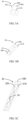


Classifications
-
- H—ELECTRICITY
- H01—ELECTRIC ELEMENTS
- H01H—ELECTRIC SWITCHES; RELAYS; SELECTORS; EMERGENCY PROTECTIVE DEVICES
- H01H13/00—Switches having rectilinearly-movable operating part or parts adapted for pushing or pulling in one direction only, e.g. push-button switch
- H01H13/70—Switches having rectilinearly-movable operating part or parts adapted for pushing or pulling in one direction only, e.g. push-button switch having a plurality of operating members associated with different sets of contacts, e.g. keyboard
- H01H13/702—Switches having rectilinearly-movable operating part or parts adapted for pushing or pulling in one direction only, e.g. push-button switch having a plurality of operating members associated with different sets of contacts, e.g. keyboard with contacts carried by or formed from layers in a multilayer structure, e.g. membrane switches
- H01H13/705—Switches having rectilinearly-movable operating part or parts adapted for pushing or pulling in one direction only, e.g. push-button switch having a plurality of operating members associated with different sets of contacts, e.g. keyboard with contacts carried by or formed from layers in a multilayer structure, e.g. membrane switches characterised by construction, mounting or arrangement of operating parts, e.g. push-buttons or keys
-
- H—ELECTRICITY
- H01—ELECTRIC ELEMENTS
- H01H—ELECTRIC SWITCHES; RELAYS; SELECTORS; EMERGENCY PROTECTIVE DEVICES
- H01H2221/00—Actuators
- H01H2221/036—Return force
- H01H2221/044—Elastic part on actuator or casing
-
- H—ELECTRICITY
- H01—ELECTRIC ELEMENTS
- H01H—ELECTRIC SWITCHES; RELAYS; SELECTORS; EMERGENCY PROTECTIVE DEVICES
- H01H2221/00—Actuators
- H01H2221/066—Actuators replaceable
Definitions
- Embodiments of the present disclosure generally relate to the electrical field, in particular a push button.
- the push switch In daily life, the push switch has the distinct advantage of simple operation. Typically, the number of buttons of the push switch has been determined during production and cannot be changed. As such, in the production process, the manufacturers need different molds or add extra procedures for switches with different numbers of buttons, thus increasing the costs. In addition, the sellers have to determine the demands for switches with different numbers of buttons based on market research while the consumers need to consider and compute the desired amounts of switches with different numbers of buttons. In the circumstance, there is often a difference between the estimated amount and the actually required amount, incurring wastes in material and human resources.
- Embodiments of the present disclosure provide a push switch, so as to at least partly solve the above-mentioned and other potential problems of the push switch according to the prior art.
- Embodiments of the present disclosure relate to a push button.
- the push button comprises: a bracket adapted to be assembled on a mounting surface, the bracket comprising at least one mounting portion, each of the at least one mounting portion comprising a snap recess and a switch element arranged on an end face of the bracket; and at least one button comprising a snap portion, the snap portion detachably snapped in a respective one of the snap recess, and the button configured to be pressed around the snap recess along a rotation direction to operate the switch element such that the push switch can be switched between an on state and an off state.
- the button is mounted in the bracket in a detachable snap fashion to enable a user to detach the button as desired, without causing damage to the button or bracket, thus providing much convenience to the user.
- the at least one mounting portion includes a plurality of mounting portions, one of the at least one button is mounted in at least two of the plurality of mounting portions, and the at least one button is configured to operate only one of a plurality of the switch elements.
- the push switch may include a plurality of mounting portions, and the buttons may differ in size and be mounted in a number of mounting portions corresponding thereto in size, such that the user can select the number of buttons as desired and mount the corresponding button combinations, making it possible to freely select the number of button positions.
- the snap recess comprises a resilient portion configured to move when the snap portion is inserted into the snap recess, so as to expand the snap recess, wherein a first protrusion is arranged at an opening of the resilient portion adjacent to the snap recess, the snap portion comprises a second protrusion, and the first protrusion is configured to abut against the second protrusion when the snap portion is snapped in the snap recess, so as to prevent the snap portion from escaping from the snap recess.
- the resilient portion extends parallel to the end face
- the snap recess further comprises a rigid portion extending parallel to the end face, wherein the first protrusion is configured to abut against the rigid portion when the snap portion is snapped in the snap recess.
- the button can be stably rotated when pressed.
- the bracket further comprises a boss portion extending from the end face along a direction away from the end face, wherein the snap recess is opened on a side surface of the boss portion.
- the button by opening the snap recess on a side different than the end face, the button can be operated smoothly.
- the rigid portion is positioned in the boss portion, and the rigid portion extends from an opening of the snap recess along a direction away from the boss portion.
- the button further comprises a limiting portion
- the bracket further comprises a limit stop, wherein the limit stop is configured to prevent the button from escaping from the bracket along a direction opposite to the rotation direction.
- the button by limiting the rotation stroke of the button, the button can be snapped more stably in the mounting portion.
- the end face is provided thereon with an opening adjacent to the limit stop
- the limiting portion comprises an arm portion extending from the button along a direction towards the bracket and a limit protrusion at an end of the arm portion adjacent to the bracket, wherein the limit protrusion is configured to be positioned below the limit stop when the snap portion is snapped in the snap recess.
- the mounting portion further comprises a reset member configured to apply to the button a force along a direction away from the bracket.
- the button is rotated towards the bracket when pressed, and is pushed back to the initial position by the reset member when the pressure is relieved after the button operated the switch element.
- the reset member comprises a resilient arm parallel to the end face, one end of the resilient arm coupled onto the bracket, and the other end of the resilient arm abutting against the button.
- the free end of the resilient arm applies to the button a force along a direction away from the bracket. In the way, upon contacting with the pressure of the button, the free end of the resilient arm can push the button back to the initial position, to thus reset the button.
- the embodiments of the present disclosure can improve the use convenience for the user.
- the term “includes” and its variants are to be read as open-ended terms that mean “includes, but is not limited to.”
- the term “based on” is to be read as “based at least in part on.”
- the term “an embodiment” or “the embodiment” is to be read as “at least one embodiment.”
- the term “another embodiment” is to be read as “at least one another embodiment.”
- the terms “first,” “second,” and the like may refer to different objects or the same object. Other meanings explicit or implicit may be covered below. Unless indicated otherwise in the context, the definitions of the terms should be consistent throughout the description.
- a typical push switch has a fixed number of buttons which could not be changed freely by a user.
- buttons of the push switch according to embodiments of the present disclosure can be installed and uninstalled without damage, and can be replaced by buttons differing in size to thus attain multiple combinations of different numbers of buttons.
- the present disclosure can significantly reduce the design and manufacturing costs while improving the flexibility of the push switch.
- Fig. 1 is a schematic diagram illustrating a push switch in its entirety according to an example embodiment of the present disclosure.
- the push switch includes a bracket 10 adapted to be assembled on a mounting surface.
- the bracket 10 includes at least one mounting portion 11.
- the structure of the mounting portion 11 will be described below with reference to Fig. 2 .
- a face of the bracket 10 for having buttons 20 mounted thereon is referred to as end face 13.
- the end face 13 is provided thereon with a boss portion 12.
- the bracket 10 includes a plurality of mounting portions 11 arranged symmetrically on both sides of the boss portion 12.
- the mounting portion 11 has a button 20 mounted therein.
- the button 20 is detachably snapped into the mounting portion 11, and can be pressed to operate a switch element 15 such that the push switch can be switched between an on state and an off state.
- the bracket 10 includes eight mounting portions 11. Every four mounting portions in the eight mounting portions 11 are arranged in a row, and the mounting portions 11 in each row are aligned.
- the button 20 in each mounting portion 11 can be removed without damage by releasing the snap connection, and thereafter can be replaced with a button of other size.
- the button 20 may be of four types of sizes, namely a single-unit size corresponding to a mounting portion 11, a double-unit size corresponding to two mounting portions 11, a three-unit size corresponding to three mounting portions 11 and a four-unit size corresponding to four mounting portions 11.
- the user may arrange each row of mounting portions 11 as desired.
- two buttons 20 each having a double-unit size are mounted in a row of the mounting portions 11. In this way, the number of the buttons can be customized.
- buttons 20 and the number of mounting portions 11 are merely provided as an example.
- the bracket 10 may include other numbers of mounting portions 11, and the mounting portions 11 may be arranged in other fashions.
- the present disclosure is not limited in the aspect.
- Figs 2-4C describe structures of the bracket and the button of the push press according to an example embodiment of the present disclosure.
- Fig. 2 is a schematic diagram of a push switch according to an example embodiment of the present disclosure, where no button 20 is mounted in a row of mounting portions 11.
- the bracket 10 of the push switch includes a plurality of mounting portions 11 as if enclosed with dotted lines.
- a mounting portion 11 corresponds to a switch position.
- the mounting portion 11 includes a switch element 15 disposed on the end face 13 for mounting a button 20, a snap recess 110 for coupling with a snap portion 210 of the button 20, an opening 14 for a receiving a limiting portion 22 on the button 20, and a reset member 170 for applying a force to the button 20.
- the reset member 170 further includes a resilient arm 171 extending parallel to the end face 13.
- the resilient arm 170 at one end is connected with the bracket 10. Adjacent to the free end of the resilient arm 171 is arranged a reset protrusion 172, to reset the button 20.
- the mounting portion 11 includes two snap recesses 110 and two openings 14.
- Fig. 3A is a schematic diagram illustrating a structure of a button 20 according to an example embodiment of the present disclosure.
- the button 20 includes a panel 230 adapted to be pressed by the user, a snap portion 210 for snapping into the snap recess 110 of the bracket 10 and arranged on the panel 230, a limiting portion 220 for mating with a limit stop 16 of the bracket 10, and an actuation portion 210 for operating the switch element 15.
- the button 20 can be pressed around the snap recess 110 along a rotation direction R to cause the actuation portion 210 to push the switch element 15 and thus operate the same.
- the button 20 includes two snap portions 210 and two limiting portions 220.
- the button 20, for example, may be mounted in a mounting portion 11 in the push switch shown in Fig. 2 .
- Fig. 3B is a schematic diagram of a structure of a button 20 according to another embodiment of the present disclosure.
- the button 20 includes a panel 230, two snap portions 210 arranged on the panel 230, two limiting portions 220, and an actuation portion 24.
- the button 20 in Fig. 3B has a greater size than the counterpart in Fig. 3A , which, for example, may be mounted into the respective snap recesses 110 of two mounting portion 11 in the push switch shown in Fig. 2 .
- the two mounting portions 11 may be mounting portions 11 arranged side by side, or may be mounting portions 11 spaced part by others, i.e., the button 20 may correspond to a double-position button, or may correspond to a multi-position button.
- Fig. 3C is a schematic diagram illustrating a structure of a button 20 according to a further example embodiment of the present disclosure.
- the button 20 includes a panel 230, three snap portions 210 arranged on the panel 230, three limiting portions 220, and an actuation portion 24.
- the button 20 in Fig. 3C has a greater size than the counterpart in Fig. 3B , which, for example, may be mounted into respective snap recesses 110 of three or four mounting portions 11 of the push switch as shown in Fig. 2 .
- a push switch having button combinations differing in number can be obtained.
- the obtained push switch is shown in Figs. 4A-4C .
- Fig. 4A is a schematic diagram illustrating a button combination of a push switch according to an example embodiment of the present disclosure.
- a row of buttons 20 is mounted on both sides of the boss portion 12 of the bracket 10, respectively.
- Each row of buttons includes two single-unit buttons each mounted in a mounting portion 11, and a double-unit button mounted in two mounting portions 11.
- a push switch with a total of six button positions is obtained.
- Fig. 4B is a schematic diagram illustrating a button combination of a push switch according to an example embodiment of the present disclosure. As shown therein, a row of buttons 20 is mounted on both sides of the boss portion 12 of the bracket 10, respectively. Each row of buttons includes two double-unit buttons each mounted in two mounting portions 11. A push switch with a total of four button positions is obtained accordingly.
- Fig. 4C is a schematic diagram illustrating a button combination of a push switch according to an example embodiment of the present disclosure. As shown therein, a row of buttons 20 is mounted on both sides of the boss portion 12 of the bracket 10, respectively. Each row of buttons includes a four-unit button mounted in four mounting portions 11. A push switch with a total of two button positions is obtained accordingly.
- Fig. 5 is a partial sectional view of the push switch along a line A-A.
- the push switch includes a bracket 10 and buttons 20 mounting on the mounting surface.
- the bracket 10 includes, for example, an end face 13 parallel to the mounting surface, a boss portion 12 extending along a direction away from the end face 13, and at least one mounting portion 11 positioned on one side of the boss portion 12.
- the button 20 is mounted in the mounting portion 11.
- the mounting portion 11 includes a snap recess 110 opened on the side surface of the boss portion 12.
- the snap recess 110 includes a resilient portion 111 and a rigid portion 113 extending parallel to the end face 13.
- the resilient portion 111 extends from the opening of the snap recess 110 along the direction away from the boss portion 12, and the rigid portion 113 is positioned in the boss portion 12.
- the button 20 includes a panel 230 adapted to be pressed by a user.
- the outer surface of the panel 230 may be flush with the outer surface of the boss portion 12.
- the panel 230 on the side facing the bracket 10 is provided with a snap portion 210 extending along a direction towards the bracket 10.
- the snap portion 210 at the end away from the panel 230 is provided with a second protrusion 211.
- the second protrusion 211 is snapped into the snap recess 110.
- the resilient portion 111 is pushed away by the snap portion 210 to expand the snap recess 110 such that the snap portion 210 can enter the snap recess 110 and be restored to the initial position after the entry of the second protrusion 211.
- the second protrusion 211 abuts against the rigid portion 113 and simultaneously abuts against the first protrusion 112 disposed at one end of the resilient portion 111, thereby being limited in the snap recess 110.
- the button 20 can be pushed around the snap recess 110 along the rotation direction R to thus rotate along the rotation direction R.
- the bracket 10 further includes a limit stop 16.
- the limit stop 16 is configured to prevent the button 20 from escaping from the bracket 10 along a direction opposite to the rotation direction R.
- the button 20 further includes a limiting portion 220 that includes an arm portion 221 extending from the button 20 along a direction towards the bracket 10, and a limit protrusion 222 at an end of the arm portion 221 adjacent to the bracket 10.
- the end face 13 is provided thereon with an opening 14 adjacent to the limit stop 16.
- the arm portion 221 extends into the opening 14 such that the limit protrusion 222 is positioned below the limit sop 16.
- Fig. 6 is a sectional view of a push switch after the key 20 is pushed away from the bracket 10 according to an example embodiment of the present disclosure. For brevity, the parts shown in Fig. 5 are not described here.
- the snap portion 210 of the key 20 has been released from the snap recess 110, and the limiting portion 220 has been released from the limit stop 16. At this time, the button 20 can be removed by the user without any wear.
Landscapes
- Push-Button Switches (AREA)
- Rotary Switch, Piano Key Switch, And Lever Switch (AREA)
Abstract
Embodiments of the present disclosure relate to a push switch. The push switch includes: a bracket (10) adapted to be assembled on a mounting surface, the bracket (10) comprising at least one mounting portion (11), each of the at least one mounting portion (11) comprising a snap recess (110) and a switch element (15) arranged on an end face (13) of the bracket (10); and at least one button (20) comprising a snap portion (210), the snap portion (210) detachably snapped in a respective one of the snap recess (110), and the button (20) configured to be pressed around the snap recess (110) along a rotation direction (R) to operate the switch element such that the push switch can be switched between an on state and an off state. In this way, the button and the bracket can be connected in a detachable snap fashion, to thus achieve damageless detachment of the button.
Description
- Embodiments of the present disclosure generally relate to the electrical field, in particular a push button.
- In daily life, the push switch has the distinct advantage of simple operation. Typically, the number of buttons of the push switch has been determined during production and cannot be changed. As such, in the production process, the manufacturers need different molds or add extra procedures for switches with different numbers of buttons, thus increasing the costs. In addition, the sellers have to determine the demands for switches with different numbers of buttons based on market research while the consumers need to consider and compute the desired amounts of switches with different numbers of buttons. In the circumstance, there is often a difference between the estimated amount and the actually required amount, incurring wastes in material and human resources.
- Embodiments of the present disclosure provide a push switch, so as to at least partly solve the above-mentioned and other potential problems of the push switch according to the prior art.
- Embodiments of the present disclosure relate to a push button. The push button comprises: a bracket adapted to be assembled on a mounting surface, the bracket comprising at least one mounting portion, each of the at least one mounting portion comprising a snap recess and a switch element arranged on an end face of the bracket; and at least one button comprising a snap portion, the snap portion detachably snapped in a respective one of the snap recess, and the button configured to be pressed around the snap recess along a rotation direction to operate the switch element such that the push switch can be switched between an on state and an off state.
- According to the embodiments of the present disclosure, the button is mounted in the bracket in a detachable snap fashion to enable a user to detach the button as desired, without causing damage to the button or bracket, thus providing much convenience to the user.
- In some embodiments, the at least one mounting portion includes a plurality of mounting portions, one of the at least one button is mounted in at least two of the plurality of mounting portions, and the at least one button is configured to operate only one of a plurality of the switch elements.
- In these embodiments, the push switch may include a plurality of mounting portions, and the buttons may differ in size and be mounted in a number of mounting portions corresponding thereto in size, such that the user can select the number of buttons as desired and mount the corresponding button combinations, making it possible to freely select the number of button positions.
- In some embodiments, the snap recess comprises a resilient portion configured to move when the snap portion is inserted into the snap recess, so as to expand the snap recess, wherein a first protrusion is arranged at an opening of the resilient portion adjacent to the snap recess, the snap portion comprises a second protrusion, and the first protrusion is configured to abut against the second protrusion when the snap portion is snapped in the snap recess, so as to prevent the snap portion from escaping from the snap recess.
- In these embodiments, by providing a resilient portion in the snap recess, wear between the snap recess and the snap portion of the button can be reduced when the button is snapped in the bracket, to thus fulfil damageless detachment of the button. Meanwhile, by providing interacting protrusions, the snap portion can be prevented from escaping from the snap recess after snapped into the latter, to thereby achieve a stable snap connection between the button and the bracket.
- In some embodiments, the resilient portion extends parallel to the end face, and the snap recess further comprises a rigid portion extending parallel to the end face, wherein the first protrusion is configured to abut against the rigid portion when the snap portion is snapped in the snap recess.
- In these embodiments, by providing a rigid portion and causing the snap portion in an assembled state to abut against the rigid portion, the button can be stably rotated when pressed.
- In some embodiments, the bracket further comprises a boss portion extending from the end face along a direction away from the end face, wherein the snap recess is opened on a side surface of the boss portion.
- In these embodiments, by opening the snap recess on a side different than the end face, the button can be operated smoothly.
- In some embodiments, the rigid portion is positioned in the boss portion, and the rigid portion extends from an opening of the snap recess along a direction away from the boss portion.
- In these embodiments, by arranging the rigid portion, as a part of the snap recess, in the boss portion and arranging the resilient portion, as the other part of the snap recess, outside the boss portion, the complexity of the structure of the boss portion can be simplified, thus reducing the design and production costs.
- In some embodiments, the button further comprises a limiting portion, and the bracket further comprises a limit stop, wherein the limit stop is configured to prevent the button from escaping from the bracket along a direction opposite to the rotation direction.
- In these embodiments, by limiting the rotation stroke of the button, the button can be snapped more stably in the mounting portion.
- In some embodiments, the end face is provided thereon with an opening adjacent to the limit stop, and the limiting portion comprises an arm portion extending from the button along a direction towards the bracket and a limit protrusion at an end of the arm portion adjacent to the bracket, wherein the limit protrusion is configured to be positioned below the limit stop when the snap portion is snapped in the snap recess.
- In these embodiments, by opening an opening in the end face to receive the limit stop, the whole size of the switch can be reduced, thus attaining a more compact and pleasing switch.
- In some embodiments, the mounting portion further comprises a reset member configured to apply to the button a force along a direction away from the bracket.
- In these embodiments, the button is rotated towards the bracket when pressed, and is pushed back to the initial position by the reset member when the pressure is relieved after the button operated the switch element.
- In some embodiments, the reset member comprises a resilient arm parallel to the end face, one end of the resilient arm coupled onto the bracket, and the other end of the resilient arm abutting against the button.
- In these embodiments, the free end of the resilient arm applies to the button a force along a direction away from the bracket. In the way, upon contacting with the pressure of the button, the free end of the resilient arm can push the button back to the initial position, to thus reset the button.
- With the design of damagelessly detaching the button, the embodiments of the present disclosure can improve the use convenience for the user.
- The above and other objectives, features, and advantages of the present disclosure will become more apparent through the following detailed description of the example embodiments with reference to the accompanying drawings. In the drawings, several embodiments of the present disclosure will be illustrated in an exemplary way, without limitation, where:
-
Fig. 1 is a schematic diagram illustrating a push switch in its entirety according to an example embodiment of the present disclosure; -
Fig. 2 is a schematic diagram illustrating a push switch according to an example embodiment of the present disclosure after some buttons were removed -
Figs. 3A-3C are schematic diagrams illustrating structures of different types of buttons of the push switch according to example embodiments of the present disclosure; -
Figs. 4A-4C are schematic diagrams illustrating different button combinations of the push switch according to example embodiments of the present disclosure; -
Fig. 5 is a partial sectional view of the push switch inFig. 1 along a line A-A; and -
Fig. 6 is a sectional view of the push switch inFig. 5 when the buttons are in a disassembled state. - Reference now will be made to the various example embodiments shown in the drawings to illustrate the principle of the present disclosure. It would be appreciated that the description on these embodiments are provided merely to enable those skilled in the art to better understand and further carry out the present disclosure, without suggesting any limitation to the scope of the present disclosure. It is worth nothing that similar or same reference symbols are used in the drawings if possible, and they are used to denote the similar or same functions. Those skilled in the art could easily realize that the alternative embodiments of the structure and method illustrated in the following description could be employed without departing from the principle of the present disclosure described here.
- As used herein, the term "includes" and its variants are to be read as open-ended terms that mean "includes, but is not limited to." The term "based on" is to be read as "based at least in part on." The term "an embodiment" or "the embodiment" is to be read as "at least one embodiment." The term "another embodiment" is to be read as "at least one another embodiment." The terms "first," "second," and the like may refer to different objects or the same object. Other meanings explicit or implicit may be covered below. Unless indicated otherwise in the context, the definitions of the terms should be consistent throughout the description.
- As stated above, a typical push switch has a fixed number of buttons which could not be changed freely by a user.
- The embodiments of the present disclosure provide a push switch having a number of buttons that can be set as desired, to solve the above-mentioned problem. Buttons of the push switch according to embodiments of the present disclosure can be installed and uninstalled without damage, and can be replaced by buttons differing in size to thus attain multiple combinations of different numbers of buttons. By utilizing buttons that can be installed and uninstalled without damage, the present disclosure can significantly reduce the design and manufacturing costs while improving the flexibility of the push switch.
-
Fig. 1 is a schematic diagram illustrating a push switch in its entirety according to an example embodiment of the present disclosure. As shown inFig. 1 , the push switch includes abracket 10 adapted to be assembled on a mounting surface. Thebracket 10 includes at least onemounting portion 11. The structure of themounting portion 11 will be described below with reference toFig. 2 . A face of thebracket 10 for havingbuttons 20 mounted thereon is referred to asend face 13. As shown inFig. 1 , theend face 13 is provided thereon with aboss portion 12. Thebracket 10 includes a plurality of mountingportions 11 arranged symmetrically on both sides of theboss portion 12. The mountingportion 11 has abutton 20 mounted therein. Thebutton 20 is detachably snapped into the mountingportion 11, and can be pressed to operate aswitch element 15 such that the push switch can be switched between an on state and an off state. In the embodiment as shown inFig. 1 , thebracket 10 includes eight mountingportions 11. Every four mounting portions in the eight mountingportions 11 are arranged in a row, and the mountingportions 11 in each row are aligned. Thebutton 20 in each mountingportion 11 can be removed without damage by releasing the snap connection, and thereafter can be replaced with a button of other size. In the embodiment, thebutton 20 may be of four types of sizes, namely a single-unit size corresponding to a mountingportion 11, a double-unit size corresponding to two mountingportions 11, a three-unit size corresponding to three mountingportions 11 and a four-unit size corresponding to four mountingportions 11. Here, the user may arrange each row of mountingportions 11 as desired. For example, twobuttons 20 each having a double-unit size are mounted in a row of the mountingportions 11. In this way, the number of the buttons can be customized. - It would be appreciated that the number of
buttons 20 and the number of mountingportions 11 are merely provided as an example. Thebracket 10 may include other numbers of mountingportions 11, and the mountingportions 11 may be arranged in other fashions. The present disclosure is not limited in the aspect. - Hereinafter, reference will be made to
Figs 2-4C to describe structures of the bracket and the button of the push press according to an example embodiment of the present disclosure. -
Fig. 2 is a schematic diagram of a push switch according to an example embodiment of the present disclosure, where nobutton 20 is mounted in a row of mountingportions 11. As shown therein, thebracket 10 of the push switch includes a plurality of mountingportions 11 as if enclosed with dotted lines. A mountingportion 11 corresponds to a switch position. The mountingportion 11 includes aswitch element 15 disposed on theend face 13 for mounting abutton 20, asnap recess 110 for coupling with asnap portion 210 of thebutton 20, anopening 14 for a receiving a limitingportion 22 on thebutton 20, and areset member 170 for applying a force to thebutton 20. In some embodiments, thereset member 170 further includes aresilient arm 171 extending parallel to theend face 13. Theresilient arm 170 at one end is connected with thebracket 10. Adjacent to the free end of theresilient arm 171 is arranged areset protrusion 172, to reset thebutton 20. In the embodiment as shown inFig. 2 , the mountingportion 11 includes twosnap recesses 110 and twoopenings 14. -
Fig. 3A is a schematic diagram illustrating a structure of abutton 20 according to an example embodiment of the present disclosure. As shown therein, thebutton 20 includes apanel 230 adapted to be pressed by the user, asnap portion 210 for snapping into thesnap recess 110 of thebracket 10 and arranged on thepanel 230, a limitingportion 220 for mating with alimit stop 16 of thebracket 10, and anactuation portion 210 for operating theswitch element 15. Thebutton 20 can be pressed around thesnap recess 110 along a rotation direction R to cause theactuation portion 210 to push theswitch element 15 and thus operate the same. In the embodiment as shown inFig. 3A , thebutton 20 includes twosnap portions 210 and two limitingportions 220. Thebutton 20, for example, may be mounted in a mountingportion 11 in the push switch shown inFig. 2 . -
Fig. 3B is a schematic diagram of a structure of abutton 20 according to another embodiment of the present disclosure. As shown therein, thebutton 20 includes apanel 230, twosnap portions 210 arranged on thepanel 230, two limitingportions 220, and anactuation portion 24. Thebutton 20 inFig. 3B has a greater size than the counterpart inFig. 3A , which, for example, may be mounted into the respective snap recesses 110 of two mountingportion 11 in the push switch shown inFig. 2 . The two mountingportions 11 may be mountingportions 11 arranged side by side, or may be mountingportions 11 spaced part by others, i.e., thebutton 20 may correspond to a double-position button, or may correspond to a multi-position button. -
Fig. 3C is a schematic diagram illustrating a structure of abutton 20 according to a further example embodiment of the present disclosure. As shown therein, thebutton 20 includes apanel 230, threesnap portions 210 arranged on thepanel 230, three limitingportions 220, and anactuation portion 24. Thebutton 20 inFig. 3C has a greater size than the counterpart inFig. 3B , which, for example, may be mounted into respective snap recesses 110 of three or four mountingportions 11 of the push switch as shown inFig. 2 . - According to the embodiments of the present disclosure, by mounting the selected different buttons shown in
Figs. 3A-3C in thebracket 10 shown inFig. 2 , a push switch having button combinations differing in number can be obtained. The obtained push switch is shown inFigs. 4A-4C . -
Fig. 4A is a schematic diagram illustrating a button combination of a push switch according to an example embodiment of the present disclosure. As shown therein, a row ofbuttons 20 is mounted on both sides of theboss portion 12 of thebracket 10, respectively. Each row of buttons includes two single-unit buttons each mounted in a mountingportion 11, and a double-unit button mounted in two mountingportions 11. Thus, a push switch with a total of six button positions is obtained. -
Fig. 4B is a schematic diagram illustrating a button combination of a push switch according to an example embodiment of the present disclosure. As shown therein, a row ofbuttons 20 is mounted on both sides of theboss portion 12 of thebracket 10, respectively. Each row of buttons includes two double-unit buttons each mounted in two mountingportions 11. A push switch with a total of four button positions is obtained accordingly. -
Fig. 4C is a schematic diagram illustrating a button combination of a push switch according to an example embodiment of the present disclosure. As shown therein, a row ofbuttons 20 is mounted on both sides of theboss portion 12 of thebracket 10, respectively. Each row of buttons includes a four-unit button mounted in four mountingportions 11. A push switch with a total of two button positions is obtained accordingly. - Hereinafter, reference will be made to
Figs. 5 and6 to describe the mounting process of the push switch according to embodiments of the present disclosure. -
Fig. 5 is a partial sectional view of the push switch along a line A-A. As shown therein, the push switch includes abracket 10 andbuttons 20 mounting on the mounting surface. Thebracket 10 includes, for example, anend face 13 parallel to the mounting surface, aboss portion 12 extending along a direction away from theend face 13, and at least one mountingportion 11 positioned on one side of theboss portion 12. Thebutton 20 is mounted in the mountingportion 11. - The mounting
portion 11 includes asnap recess 110 opened on the side surface of theboss portion 12. Thesnap recess 110 includes aresilient portion 111 and arigid portion 113 extending parallel to theend face 13. Theresilient portion 111 extends from the opening of thesnap recess 110 along the direction away from theboss portion 12, and therigid portion 113 is positioned in theboss portion 12. - The
button 20 includes apanel 230 adapted to be pressed by a user. The outer surface of thepanel 230 may be flush with the outer surface of theboss portion 12. Thepanel 230 on the side facing thebracket 10 is provided with asnap portion 210 extending along a direction towards thebracket 10. Thesnap portion 210 at the end away from thepanel 230 is provided with asecond protrusion 211. Thesecond protrusion 211 is snapped into thesnap recess 110. When thesnap portion 210 is inserted into thesnap recess 110, theresilient portion 111 is pushed away by thesnap portion 210 to expand thesnap recess 110 such that thesnap portion 210 can enter thesnap recess 110 and be restored to the initial position after the entry of thesecond protrusion 211. As shown inFig. 5 , thesecond protrusion 211 abuts against therigid portion 113 and simultaneously abuts against thefirst protrusion 112 disposed at one end of theresilient portion 111, thereby being limited in thesnap recess 110. In the state as shown inFig. 5 , thebutton 20 can be pushed around thesnap recess 110 along the rotation direction R to thus rotate along the rotation direction R. - In order to prevent the
button 20 from escaping from thebracket 10 when rotating, thebracket 10 further includes alimit stop 16. Thelimit stop 16 is configured to prevent thebutton 20 from escaping from thebracket 10 along a direction opposite to the rotation direction R. Correspondingly, thebutton 20 further includes a limitingportion 220 that includes anarm portion 221 extending from thebutton 20 along a direction towards thebracket 10, and alimit protrusion 222 at an end of thearm portion 221 adjacent to thebracket 10. In addition, theend face 13 is provided thereon with anopening 14 adjacent to thelimit stop 16. Thearm portion 221 extends into theopening 14 such that thelimit protrusion 222 is positioned below thelimit sop 16. When not pressed by the user, thebutton 20 is subjected to a force applied by thereset member 170 as shown inFig. 2 in a direction away from thebracket 10 such that thelimit protrusion 222 is kept to abut against thelimit stop 16. - When the
button 20 is to be removed, the user only needs to push thebutton 20 along a direction parallel to theend face 13 and away from theboss portion 12.Fig. 6 is a sectional view of a push switch after the key 20 is pushed away from thebracket 10 according to an example embodiment of the present disclosure. For brevity, the parts shown inFig. 5 are not described here. - As shown in
Fig. 6 , thesnap portion 210 of the key 20 has been released from thesnap recess 110, and the limitingportion 220 has been released from thelimit stop 16. At this time, thebutton 20 can be removed by the user without any wear. - Although the claims of the present disclosure are formulated for a specific combination of features, it would be appreciated that the scope of the present disclosure further covers any novel feature or any novel combination of features generalized explicitly or implicitly from the contents disclosed here regardless of whether it relates to the same solution currently claimed in any one of the claims.
Claims (10)
- A push switch, characterized by comprising:a bracket (10) adapted to be assembled on a mounting surface, the bracket (10) comprising at least one mounting portion (11), each of the at least one mounting portion (11) comprising a snap recess (110) and a switch element (15) arranged on an end face (13) of the bracket (10); andat least one button (20) comprising a snap portion (210), the snap portion (210) detachably snapped in a respective one of the snap recess (110), and the button (20) configured to be pressed around the snap recess (110) along a rotation direction (R) to operate the switch element such that the push switch can be switched between an on state and an off state.
- The push switch of claim 1, characterized in that the at least one mounting portion (11) includes a plurality of mounting portions (11), one of the at least one button (20) is mounted in at least two of the plurality of mounting portions (11), and the at least one button (20) is configured to operate only one of a plurality of the switch elements (15).
- The push switch of claim 1, characterized in that the snap recess (110) comprises a resilient portion (111) configured to move when the snap portion (210) is inserted into the snap recess (110), so as to expand the snap recess (110), wherein a first protrusion (112) is arranged at an opening of the resilient portion (111) adjacent to the snap recess (110), the snap portion (210) comprises a second protrusion (211), and the first protrusion (112) is configured to abut against the second protrusion (211) when the snap portion (210) is snapped in the snap recess (110), so as to prevent the snap portion (210) from escaping from the snap recess (110).
- The push switch of claim 3, characterized in that the resilient portion (111) extends parallel to the end face (13), and the snap recess (110) further comprises a rigid portion (113) extending parallel to the end face, wherein the first protrusion (112) is configured to abut against the rigid portion (113) when the snap portion (210) is snapped in the snap recess (110).
- The push switch of claim 4, characterized in that the bracket (10) further comprises a boss portion (12) extending from the end face (13) along a direction away from the end face (13), wherein the snap recess (110) is opened on a side surface of the boss portion (12).
- The push switch of claim 5, characterized in that the rigid portion (113) is positioned in the boss portion (12), and the rigid portion (113) extends from an opening of the snap recess (110) along a direction away from the boss portion (12).
- The push switch of claim 1, characterized in that the button (20) further comprises a limiting portion (220), and the bracket (10) further comprises a limit stop (16), wherein the limit stop (16) is configured to prevent the button (20) from escaping from the bracket (10) along a direction opposite to the rotation direction (R).
- The push switch of claim 7, characterized in that the end face (13) is provided thereon with an opening (14) adjacent to the limit stop (16), and the limiting portion (220) comprises an arm portion (221) extending from the button (20) along a direction towards the bracket (10) and a limit protrusion (222) at an end of the arm portion (221) adjacent to the bracket (10), wherein the limit protrusion (222) is configured to be positioned below the limit stop (16) when the snap portion (210) is snapped in the snap recess (110).
- The push switch of claim 1, characterized in that the mounting portion (11) further comprises a reset member (170) configured to apply to the button (20) a force along a direction away from the bracket (10).
- The push switch of claim 9, characterized in that the reset member (170) comprises a resilient arm (171) parallel to the end face (13), one end of the resilient arm (171) coupled onto the bracket (10), and the other end of the resilient arm (171) abutting against the button (20).
Applications Claiming Priority (1)
| Application Number | Priority Date | Filing Date | Title |
|---|---|---|---|
| CN202123339695.0U CN217280527U (en) | 2021-12-28 | 2021-12-28 | Push switch |
Publications (1)
| Publication Number | Publication Date |
|---|---|
| EP4207232A1 true EP4207232A1 (en) | 2023-07-05 |
Family
ID=82891142
Family Applications (1)
| Application Number | Title | Priority Date | Filing Date |
|---|---|---|---|
| EP22307050.9A Withdrawn EP4207232A1 (en) | 2021-12-28 | 2022-12-27 | Push button |
Country Status (2)
| Country | Link |
|---|---|
| EP (1) | EP4207232A1 (en) |
| CN (1) | CN217280527U (en) |
Citations (2)
| Publication number | Priority date | Publication date | Assignee | Title |
|---|---|---|---|---|
| EP0053264A2 (en) * | 1980-12-03 | 1982-06-09 | Bizerba-Werke Wilhelm Kraut GmbH & Co. KG. | Key arrangement |
| TWI623005B (en) * | 2015-11-19 | 2018-05-01 | 華碩電腦股份有限公司 | Key structure |
-
2021
- 2021-12-28 CN CN202123339695.0U patent/CN217280527U/en active Active
-
2022
- 2022-12-27 EP EP22307050.9A patent/EP4207232A1/en not_active Withdrawn
Patent Citations (2)
| Publication number | Priority date | Publication date | Assignee | Title |
|---|---|---|---|---|
| EP0053264A2 (en) * | 1980-12-03 | 1982-06-09 | Bizerba-Werke Wilhelm Kraut GmbH & Co. KG. | Key arrangement |
| TWI623005B (en) * | 2015-11-19 | 2018-05-01 | 華碩電腦股份有限公司 | Key structure |
Also Published As
| Publication number | Publication date |
|---|---|
| CN217280527U (en) | 2022-08-23 |
Similar Documents
| Publication | Publication Date | Title |
|---|---|---|
| US8957338B2 (en) | Trigger action switch operator | |
| CN101499388A (en) | Switch device | |
| US8052438B1 (en) | Connector module | |
| CA3059183C (en) | Switching and operating assembly of a switch | |
| US7119297B2 (en) | Push button | |
| EP3828451A1 (en) | Solenoid valve | |
| US20030116976A1 (en) | Battery latch | |
| EP2713381B1 (en) | Push-button switch, selector switch, and fixing component therefor | |
| EP1503392B1 (en) | Switch Assembly | |
| KR101423145B1 (en) | Multi-operation switch device | |
| WO2017038877A1 (en) | Substrate connection structure | |
| WO2025246577A1 (en) | Key module, chassis ear structure and server | |
| JP5341810B2 (en) | Combined operation type input device | |
| CN217280527U (en) | Push switch | |
| EP3629356B1 (en) | Electromagnetic relay | |
| KR200460533Y1 (en) | Slider switch unit | |
| CN102498534B (en) | operating mechanism | |
| CN113223887A (en) | Push-button switch | |
| JP2003303532A (en) | Combined operation type electric component | |
| CN224233031U (en) | Connector with a plurality of connectors | |
| AU2017356333B2 (en) | Load break switch | |
| CN216902611U (en) | Intelligent switch | |
| CN217690851U (en) | Switch assembly for circuit board shell, circuit board shell and air conditioner | |
| EP4137724B1 (en) | Solenoid valve manifold | |
| JP2000164070A (en) | Switch |
Legal Events
| Date | Code | Title | Description |
|---|---|---|---|
| PUAI | Public reference made under article 153(3) epc to a published international application that has entered the european phase |
Free format text: ORIGINAL CODE: 0009012 |
|
| STAA | Information on the status of an ep patent application or granted ep patent |
Free format text: STATUS: REQUEST FOR EXAMINATION WAS MADE |
|
| 17P | Request for examination filed |
Effective date: 20221227 |
|
| AK | Designated contracting states |
Kind code of ref document: A1 Designated state(s): AL AT BE BG CH CY CZ DE DK EE ES FI FR GB GR HR HU IE IS IT LI LT LU LV MC ME MK MT NL NO PL PT RO RS SE SI SK SM TR |
|
| STAA | Information on the status of an ep patent application or granted ep patent |
Free format text: STATUS: THE APPLICATION IS DEEMED TO BE WITHDRAWN |
|
| 18D | Application deemed to be withdrawn |
Effective date: 20250701 |