EP4207141A1 - Display - Google Patents
Display Download PDFInfo
- Publication number
- EP4207141A1 EP4207141A1 EP20864330.4A EP20864330A EP4207141A1 EP 4207141 A1 EP4207141 A1 EP 4207141A1 EP 20864330 A EP20864330 A EP 20864330A EP 4207141 A1 EP4207141 A1 EP 4207141A1
- Authority
- EP
- European Patent Office
- Prior art keywords
- roller
- housing body
- display device
- shaft
- display screen
- Prior art date
- Legal status (The legal status is an assumption and is not a legal conclusion. Google has not performed a legal analysis and makes no representation as to the accuracy of the status listed.)
- Pending
Links
Images



Classifications
-
- G—PHYSICS
- G06—COMPUTING OR CALCULATING; COUNTING
- G06F—ELECTRIC DIGITAL DATA PROCESSING
- G06F1/00—Details not covered by groups G06F3/00 - G06F13/00 and G06F21/00
- G06F1/16—Constructional details or arrangements
- G06F1/1613—Constructional details or arrangements for portable computers
- G06F1/1633—Constructional details or arrangements of portable computers not specific to the type of enclosures covered by groups G06F1/1615 - G06F1/1626
- G06F1/1637—Details related to the display arrangement, including those related to the mounting of the display in the housing
- G06F1/1652—Details related to the display arrangement, including those related to the mounting of the display in the housing the display being flexible, e.g. mimicking a sheet of paper, or rollable
-
- G—PHYSICS
- G09—EDUCATION; CRYPTOGRAPHY; DISPLAY; ADVERTISING; SEALS
- G09F—DISPLAYING; ADVERTISING; SIGNS; LABELS OR NAME-PLATES; SEALS
- G09F9/00—Indicating arrangements for variable information in which the information is built-up on a support by selection or combination of individual elements
- G09F9/30—Indicating arrangements for variable information in which the information is built-up on a support by selection or combination of individual elements in which the desired character or characters are formed by combining individual elements
- G09F9/301—Indicating arrangements for variable information in which the information is built-up on a support by selection or combination of individual elements in which the desired character or characters are formed by combining individual elements flexible foldable or roll-able electronic displays, e.g. thin LCD, OLED
-
- G—PHYSICS
- G06—COMPUTING OR CALCULATING; COUNTING
- G06F—ELECTRIC DIGITAL DATA PROCESSING
- G06F1/00—Details not covered by groups G06F3/00 - G06F13/00 and G06F21/00
- G06F1/16—Constructional details or arrangements
- G06F1/1613—Constructional details or arrangements for portable computers
- G06F1/1633—Constructional details or arrangements of portable computers not specific to the type of enclosures covered by groups G06F1/1615 - G06F1/1626
- G06F1/1637—Details related to the display arrangement, including those related to the mounting of the display in the housing
- G06F1/1641—Details related to the display arrangement, including those related to the mounting of the display in the housing the display being formed by a plurality of foldable display components
-
- H—ELECTRICITY
- H04—ELECTRIC COMMUNICATION TECHNIQUE
- H04M—TELEPHONIC COMMUNICATION
- H04M1/00—Substation equipment, e.g. for use by subscribers
- H04M1/02—Constructional features of telephone sets
- H04M1/0202—Portable telephone sets, e.g. cordless phones, mobile phones or bar type handsets
- H04M1/026—Details of the structure or mounting of specific components
- H04M1/0266—Details of the structure or mounting of specific components for a display module assembly
- H04M1/0268—Details of the structure or mounting of specific components for a display module assembly including a flexible display panel
Definitions
- the present disclosure relates to the field of display technologies, and more particularly, relates to a display device.
- Computer data may be displayed by display devices in forms of words, numerals, symbols, or intuitive images. Furthermore, by transmitting orders or data into hardware and software of computer systems with a keyboard, display contents may be added, deleted, or changed anytime.
- the display devices may be divided into a plasma type, a liquid crystal type, a light-emitting diode type, and a cathode ray type according to their luminescent principles.
- An aim of the present disclosure is to provide a display device that can solve a following problem: conventional devices are not portable because they occupy much space due to their large bodies.
- a display device including: a housing body; a first shaft, wherein the first shaft is rotatably mounted at two opposite inner sidewalls of the housing body; a first roller, wherein the first roller is sleeved on an exterior of the first shaft and is firmly connected to the first shaft; a flexible display screen, wherein the flexible display screen is spirally sleeved on an outer surface of the first roller, an end of the flexible display screen is connected to the first roller, and another end of the flexible display screen is connected to an exterior of the housing body; a main board, wherein the main board is attached to an interior of the first roller or the exterior of the housing body; and a flexible circuit board, wherein the flexible circuit board is connected to the end of the flexible display screen and is connected to the main board; wherein when the display device is in use, the entire flexible display screen is stretched to the exterior of the housing body.
- the display device includes: a first connector disposed on the main board; and a second connector disposed on the flexible circuit board and electrically connected to the first connector.
- the display device includes: a changeover flexible circuit board, wherein the changeover flexible circuit board surrounds the first shaft and is disposed between the outer surface of the first roller and an inner surface of the flexible display screen, an end of the changeover flexible circuit board is connected to the main board, and another end of the changeover flexible circuit board is connected to the flexible circuit board.
- the first roller includes: a main body of the first roller, wherein the main body of the first roller is a cylinder; and an opening of the first roller, wherein the opening of the first roller is defined on a sidewall of the main body of the first roller; wherein the main board is disposed in the main body of the first roller and corresponds to the opening of the first roller; and the flexible circuit board is disposed at the opening of the first roller and is attached to the main board.
- the first roller further includes: a filling substance, wherein the filling substance is attached to a surface of the flexible circuit board and fills the opening of the first roller; wherein an outer surface of the filling substance and an outer sidewall of the main body of the first roller is disposed at a same curved surface.
- a sidewall of the housing body is provided with an opening of the housing body, and the flexible display screen passes through the opening of the housing body.
- the display device includes: a second shaft, wherein the second shaft is rotatably mounted at two opposite inner sidewalls of the housing body, and a central axis of the second shaft is parallel to a central axis of the first shaft; and a second roller, wherein the second roller is sleeved on an exterior of the second shaft and is firmly connected to the second shaft; wherein when the flexible display screen is rolled up, the flexible display screen is tangent to an outer surface of the second roller.
- the central axis of the first shaft is parallel to a sidewall, which is provided with an opening of the housing body, of the housing body; and a distance between the sidewall, which is provided with the opening of the housing body, of the housing body and the central axis of the second shaft is greater than a distance between the sidewall, which is provided with the opening of the housing body, of the housing body and the central axis of the first shaft; or the distance between the sidewall, which is provided with the opening of the housing body, of the housing body and the central axis of the second shaft is less than the distance between the sidewall, which is provided with the opening of the housing body, of the housing body and the central axis of the first shaft.
- the display device includes: a back board, wherein the back board is spirally sleeved on an outer surface of the second roller; when the display device is in use, the flexible display screen is disposed on the back board.
- the display device includes: a fixing board, wherein the fixing board is mounted at the first roller and is connected to an end of the flexible display screen.
- the present disclosure relates to a display device.
- a flexible screen is completely stretched to an exterior of a housing body.
- the flexible display screen is rolled up to be spirally sleeved on a first roller. Therefore, a size of the display device can be reduced, and portability of the display device can be improved.
- a structure in which a first feature is "on" a second feature may include an embodiment in which the first feature directly contacts the second feature and may also include an embodiment in which an additional feature is formed between the first feature and the second feature.
- a structure in which a first feature is "mounted on” or “connected to” a second feature may include an embodiment in which the first feature directly mounted on or connected to the second feature and may also include an embodiment in which the first feature is mounted on or connected to the second feature by an additional feature.
- the present embodiment provides a display device 100, including: a housing body 1, a first shaft 2, a first roller 3, a flexible display screen 4, a main board 5, and a flexible circuit board 6.
- a sidewall of the housing body 1 is provided with an opening 7 of the housing body, and the flexible display screen 4 passes through the opening 7 of the housing body.
- the first shaft 2 is rotatably mounted at two opposite inner sidewalls of the housing body 1.
- the first shaft 2 can be freely rotated with respect to the housing body 1.
- the first roller 3 is sleeved on an exterior of the first shaft 2 and is firmly connected to the first shaft 2. That is, the first roller 3 is attached to the second shaft 2, so that the first shaft 2 can drive the first roller 3 to rotate, thereby stretching or rolling up the flexible display screen 4.
- the first roller 3 includes a main body 31 of the first roller and an opening 32 of the first roller.
- the main body 31 of the first roller is a cylinder, and the opening 32 of the first roller is defined at a sidewall of the main body 31 of the first roller.
- the main board 5 is disposed in the main body 31 of the first roller and corresponds to the opening 32 of the first roller.
- the main board 5 is fixed in the first roller 3.
- the main board 5 is fixed at the first shaft 2 by a support 8. Because the first shaft 2 and the first roller 3 are fixed to each other, the first shaft 2, the first roller 3, and the main board 5 are fixed to each other.
- the flexible circuit board 6 is disposed at the opening 32 of the first roller and is attached to the main board 5.
- the flexible circuit board 6 may be attached to the main board 5 by an adhesive.
- the flexible display screen 4 is spirally sleeved on an outer surface of the first roller 3, an end of the flexible display screen 4 is connected to the first roller 3, and another end of the flexible display screen 4 extends to an exterior of the housing body 1.
- an end of the flexible display screen 4 is connected to flexible circuit board 6 by an adhesive, and the another end of the flexible display screen 4 passes through the opening 7 of the housing body and extends to the exterior of the housing body 1.
- the flexible display screen 4 is completely stretched to the exterior of the housing body 1.
- the first roller 3 further includes a filling substance 9 attached to a surface of the flexible circuit board 6 and filling the opening 32 of the first roller.
- An outer surface of the filling substance 8 and an outer sidewall of the main body 31 of the first roller is at a same curved surface. Due to the filling substance 9, an outer surface of the first roller 3 may be a complete curved surface. Therefore, when the flexible display screen 4 is rolled up, it can be well sleeved on the outer surface of the first roller 3.
- the display device 100 further includes a changeover flexible circuit board 10 surrounding the first shaft 2 and disposed between the outer surface of the first roller 3 and an inner surface of the flexible display screen 4.
- An end of the changeover flexible circuit board 10 is connected to the main board 5, and another end of the changeover flexible circuit board 10 is connected to the flexible circuit board 6.
- the flexible circuit board 6 and the main board 5 are electrically connected to each other.
- the display device 100 further includes a reinforcing element 17 disposed on a surface of the flexible display screen 4 contacting the main board 5.
- the reinforcing element 17 is mainly configured to distribute applied forces generated when the display device 100 is in use, thereby firmly connecting the flexible display screen 4 to the main board 5 and preventing them from being separated.
- the first roller 3 clockwise rotates, and when the flexible display screen 4 is rolled up, the first roller 3 counterclockwise rotates.
- the first roller 3 counterclockwise rotates, and when the flexible display screen 4 is rolled up, the first roller 3 clockwise rotates.
- the first roller 3 when the flexible display screen 4 is unfolded, the first roller 3 clockwise rotates, and when the flexible display screen 4 is rolled up, the first roller 3 counterclockwise rotates.
- the flexible screen 4 when the display device 100 is in use, the flexible screen 4 is completely stretched to the exterior of the housing body 1.
- the flexible display screen 4 is rolled up to be spirally sleeved on the first roller 3. Therefore, a size of the display device 100 can be reduced, and portability of the display device 100 can be improved.
- the present embodiment includes most characteristics of the first embodiment.
- a difference between the present embodiment and the first embodiment is: in the present embodiment, the flexible circuit board 6 is electrically connected to the main board 5 by a first connector 11 and a second connector instead of the changeover flexible circuit board 10 of the first embodiment.
- the display device 100 further includes the first connector 11 and the second connector 12.
- the first connector 11 is disposed on the main board 5, and the second connector 12 is disposed on the flexible circuit board 6 and is electrically connected to the first connector 11.
- the flexible screen 4 when the display device 100 is in use, the flexible screen 4 is completely stretched to the exterior of the housing body 1.
- the flexible display screen 4 is rolled up to be spirally sleeved on the first roller 3. Therefore, a size of the display device 100 can be reduced, so that portability of the display device 100 can be improved.
- the present embodiment includes all of the characteristics of the first embodiment.
- the display device 100 further includes: a second shaft 13 and a second roller 14.
- the second shaft 13 is rotatably mounted at two opposite inner sidewalls of the housing body 1, and a central axis of the second shaft 13 is parallel to a central axis of the first shaft 2.
- the second roller 14 is sleeved on an exterior of the second shaft and is firmly connected to the second shaft 13.
- the first shaft 2 and the second shaft 13 may respectively drive the first roller 3 and the second roller 14 to rotate. That is, the first shaft 2, the second shaft 13, the first roller 3, and the second roller 14 may simultaneously clockwise or counterclockwise rotate, and a rotation rate of the first roller 3 and that of the second roller 14 are same.
- the central axis of the first shaft 2 is parallel to a sidewall, which is provided with the opening 7 of the housing body, of the housing body, and a distance between the sidewall, which is provided with the opening 7 of the housing body, of the housing body and a central axis of the second roller 13 is greater than a distance between the sidewall, which is provided with the opening 7 of the housing body, of the housing body and the central axis of the second shaft 2.
- a vertical distance between the central axis of the second shaft 13 and the sidewall, which is provided with the opening 7 of the housing body, of the housing body is greater than a vertical distance between the central axis of the first shaft 2 and the sidewall, which is provided with the opening 7 of the housing body, of the housing body.
- the flexible display screen 4 when the flexible display screen 4 is rolled up, the flexible display screen 4 is tangent to an outer surface of the second roller 14.
- the flexible display screen 4 may be rotatably sleeved on the outer surface of the first roller 3.
- An end of the flexible display screen 4 is connected to the flexible circuit board 6, another end of the flexible display screen 4 extends to and surrounds the second roller 13, is attached to a curved surface of the second roller 14 away from the first roller 3, and finally passes through the opening 7 of the housing body and extends to the exterior of the housing body 1.
- the flexible screen 4 when the display device 100 is in use, the flexible screen 4 is completely stretched to the exterior of the housing body 1.
- the flexible display screen 4 is rolled up to be spirally sleeved on the first roller 3. Therefore, a size of the display device 100 can be reduced, so that portability of the display device 100 can be improved.
- the present embodiment includes most characteristics of the third embodiment, and a difference between the present embodiment and the third embodiment is: in the present embodiment, the distance between the sidewall, which is provided with the opening 7 of the housing body, of the housing body and a central axis of the second roller 13 is less than the distance between the sidewall, which is provided with the opening 7 of the housing body, of the housing body and the central axis of the second shaft 2. That is, the vertical distance between the central axis of the second shaft 13 and the sidewall, which is provided with the opening 7 of the housing body, of the housing body is less than the vertical distance between the central axis of the first shaft 2 and the sidewall, which is provided with the opening 7 of the housing body, of the housing body.
- the flexible display screen 4 when the flexible display screen 4 is rolled up, the flexible display screen 4 is tangent to the outer surface of the second roller 14.
- the flexible display screen 4 may be rotatably sleeved on the outer surface of the first roller 3.
- An end of the flexible display screen 4 is connected to the flexible circuit board 6, another end of the flexible display screen 4 is tangent to the outer surface of the second roller 14, passes through the opening 7 of the housing body, and extends to the exterior of the housing body 1.
- the second roller 14 can control a position of the flexible display screen 4, thereby preventing warpage of the flexible display screen 4 in the housing body 1, and reducing a number of bending times of the flexible display screen 4 in the housing body 1.
- the flexible screen 4 when the display device 100 is in use, the flexible screen 4 is completely stretched to the exterior of the housing body 1.
- the flexible display screen 4 is rolled up to be spirally sleeved on the first roller 3. Therefore, a size of the display device 100 can be reduced, so that portability of the display device 100 can be improved.
- the present embodiment includes all of the characteristics of the fourth embodiment.
- the display device 100 further includes a back board 15.
- the back board 15 is spirally sleeved on the outer surface of the second roller 14.
- the flexible display screen 4 is disposed on the back board 15.
- the back board 15 can improve flatness of the unfolded flexible display screen 4.
- the back board 15 can also protect the flexible display screen 4, enhancing stability of the entire display device 100.
- the flexible screen 4 when the display device 100 is in use, the flexible screen 4 is completely stretched to the exterior of the housing body 1.
- the flexible display screen 4 is rolled up to be spirally sleeved on the first roller 3. Therefore, a size of the display device 100 can be reduced, so that portability of the display device 100 can be improved.
- the present embodiment includes most of the characteristics of the first embodiment, and a difference between the present embodiment and the first embodiment is: in the present embodiment, the main board 5 is disposed on the exterior of the hosing body instead of the interior of the main body of the first roller.
- the display device 100 further includes a fixing board 16 mounted at the first roller 3 and connected to an end of the flexible display screen 4.
- the fixing board 16 may be mounted at the first roller 3 by a support.
- the flexible display screen 4 is spirally sleeved on the first roller 3, an end of the flexible display screen 4 is fixed at the fixing board, and another end of the flexible display screen is connected to the flexible circuit board 6.
- the flexible circuit board 6 is attached to the main board 5.
- the flexible screen 4 when the display device 100 is in use, the flexible screen 4 is completely stretched to the exterior of the housing body 1.
- the flexible display screen 4 is rolled up to be sleeved on the first roller 3. Therefore, a size of the display device 100 can be reduced, so that portability of the display device 100 can be improved.
Landscapes
- Engineering & Computer Science (AREA)
- Theoretical Computer Science (AREA)
- Computer Hardware Design (AREA)
- Physics & Mathematics (AREA)
- General Physics & Mathematics (AREA)
- Human Computer Interaction (AREA)
- General Engineering & Computer Science (AREA)
- Devices For Indicating Variable Information By Combining Individual Elements (AREA)
Abstract
Description
- The present disclosure relates to the field of display technologies, and more particularly, relates to a display device.
- Computer data may be displayed by display devices in forms of words, numerals, symbols, or intuitive images. Furthermore, by transmitting orders or data into hardware and software of computer systems with a keyboard, display contents may be added, deleted, or changed anytime. The display devices may be divided into a plasma type, a liquid crystal type, a light-emitting diode type, and a cathode ray type according to their luminescent principles.
- As a vital display technology, flexible screens have been developed over the past few years. Compared with conventional screens, the flexible screens have significant merits such as thin and light body and low power consumption. In addition, due to bendability and flexibility of the flexible screens, application fields thereof have become increasingly wide.
- Nowadays, electronic devices, e.g., cellphones and tablets, are widely used. Flat electronic devices can no longer satisfy people's requirements of space-saving and portable products because demands for electronic products are continuously raised following developments of technologies. As a result, it is necessary to provide a novel display device to address the above issue.
- An aim of the present disclosure is to provide a display device that can solve a following problem: conventional devices are not portable because they occupy much space due to their large bodies.
- To solve the above problem, the present disclosure provides a display device, including: a housing body; a first shaft, wherein the first shaft is rotatably mounted at two opposite inner sidewalls of the housing body; a first roller, wherein the first roller is sleeved on an exterior of the first shaft and is firmly connected to the first shaft; a flexible display screen, wherein the flexible display screen is spirally sleeved on an outer surface of the first roller, an end of the flexible display screen is connected to the first roller, and another end of the flexible display screen is connected to an exterior of the housing body; a main board, wherein the main board is attached to an interior of the first roller or the exterior of the housing body; and a flexible circuit board, wherein the flexible circuit board is connected to the end of the flexible display screen and is connected to the main board; wherein when the display device is in use, the entire flexible display screen is stretched to the exterior of the housing body.
- Furthermore, the display device includes: a first connector disposed on the main board; and a second connector disposed on the flexible circuit board and electrically connected to the first connector.
- Furthermore, the display device includes: a changeover flexible circuit board, wherein the changeover flexible circuit board surrounds the first shaft and is disposed between the outer surface of the first roller and an inner surface of the flexible display screen, an end of the changeover flexible circuit board is connected to the main board, and another end of the changeover flexible circuit board is connected to the flexible circuit board.
- Furthermore, the first roller includes: a main body of the first roller, wherein the main body of the first roller is a cylinder; and an opening of the first roller, wherein the opening of the first roller is defined on a sidewall of the main body of the first roller; wherein the main board is disposed in the main body of the first roller and corresponds to the opening of the first roller; and the flexible circuit board is disposed at the opening of the first roller and is attached to the main board.
- Furthermore, the first roller further includes: a filling substance, wherein the filling substance is attached to a surface of the flexible circuit board and fills the opening of the first roller; wherein an outer surface of the filling substance and an outer sidewall of the main body of the first roller is disposed at a same curved surface.
- Furthermore, a sidewall of the housing body is provided with an opening of the housing body, and the flexible display screen passes through the opening of the housing body.
- Furthermore, the display device includes: a second shaft, wherein the second shaft is rotatably mounted at two opposite inner sidewalls of the housing body, and a central axis of the second shaft is parallel to a central axis of the first shaft; and a second roller, wherein the second roller is sleeved on an exterior of the second shaft and is firmly connected to the second shaft; wherein when the flexible display screen is rolled up, the flexible display screen is tangent to an outer surface of the second roller.
- Furthermore, the central axis of the first shaft is parallel to a sidewall, which is provided with an opening of the housing body, of the housing body; and a distance between the sidewall, which is provided with the opening of the housing body, of the housing body and the central axis of the second shaft is greater than a distance between the sidewall, which is provided with the opening of the housing body, of the housing body and the central axis of the first shaft; or the distance between the sidewall, which is provided with the opening of the housing body, of the housing body and the central axis of the second shaft is less than the distance between the sidewall, which is provided with the opening of the housing body, of the housing body and the central axis of the first shaft.
- Furthermore, the display device includes: a back board, wherein the back board is spirally sleeved on an outer surface of the second roller; when the display device is in use, the flexible display screen is disposed on the back board.
- Furthermore, the display device includes: a fixing board, wherein the fixing board is mounted at the first roller and is connected to an end of the flexible display screen.
- Regarding the beneficial effects: the present disclosure relates to a display device. When the display device is in use, a flexible screen is completely stretched to an exterior of a housing body. When the display device is idle, the flexible display screen is rolled up to be spirally sleeved on a first roller. Therefore, a size of the display device can be reduced, and portability of the display device can be improved.
- The accompanying figures to be used in the description of embodiments of the present disclosure or prior art will be described in brief to more clearly illustrate the technical solutions of the embodiments or the prior art. The accompanying figures described below are only part of the embodiments of the present disclosure, from which those skilled in the art can derive further figures without making any inventive efforts.
-
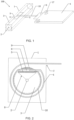
FIG. 1 is a structural schematic view showing a display device according to a first embodiment. -
FIG. 2 a sectional view showing the display device according to the first embodiment taken along line A-A. -
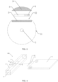
FIG. 3 is a structural schematic view showing a first roller of the display device. -
FIG. 4 is a structural schematic view showing a display device according to a second embodiment. -
FIG. 5 is a sectional view showing the display device according to the second embodiment taken along line B-B. -
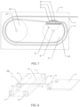
FIG. 6 is a structural schematic view showing a display device according to a third embodiment. -
FIG. 7 is a sectional view showing a display device according to the third embodiment taken along line C-C. -
FIG. 8 is a structural schematic view showing a display device according to a fourth embodiment. -
FIG. 9 is a sectional view showing the display device according to the fourth embodiment taken along line D-D. -
FIG. 10 is a structural schematic view showing a display device according to a fifth embodiment. -
FIG. 11 is a structural schematic view showing a display device according to a sixth embodiment. - Number references are as follows:
-
display device 100; -
housing body 1,first shaft 2; -
first roller 3,flexible display screen 4; -
main board 5,flexible circuit board 6; - opening 7 of the housing body, support 8;
- filling
substance 9, changeoverflexible circuit board 10; -
first connector 11,second connector 12; -
second shaft 13,second roller 14; -
back board 15,fixing board 16; - reinforcing
element 17; -
main body 31 of the first roller, opening 32 of the first roller. - Preferred embodiments of the present disclosure are illustrated below with reference to accompanying drawings to prove that the present disclosure can be implemented. The embodiments are used to fully describe technical solutions of the present disclosure so that those skilled in the art may clearly and easily understand the technical solutions. The present disclosure may be realized by many different types of embodiments; therefore, the scope of protection of the present disclosure is not limited to the embodiments mentioned in the specification.
- It should be understood that terms such as "upper", "lower", "front", "rear", "left", "right", "inside", "outside," "lateral", as well as derivative thereof should be construed to refer to the orientation as then described or as shown in the drawings under discussion. These relative terms are for convenience of description, do not require that the present disclosure be constructed or operated in a particular orientation, and shall not be construed as causing limitations to the present disclosure.
- The identical or similar reference numerals constantly denote the identical or similar elements or elements having the identical or similar functions. In addition, for the sake of better understanding and description, the size and thickness of each component shown in the drawings are arbitrarily shown, but the present disclosure is not limited thereto.
- It should be noted that a structure in which a first feature is "on" a second feature may include an embodiment in which the first feature directly contacts the second feature and may also include an embodiment in which an additional feature is formed between the first feature and the second feature. It should be noted that a structure in which a first feature is "mounted on" or "connected to" a second feature may include an embodiment in which the first feature directly mounted on or connected to the second feature and may also include an embodiment in which the first feature is mounted on or connected to the second feature by an additional feature.
- As shown in
FIG. 1 and FIG. 2 , the present embodiment provides adisplay device 100, including: ahousing body 1, afirst shaft 2, afirst roller 3, aflexible display screen 4, amain board 5, and aflexible circuit board 6. - As shown in
FIG. 1 and FIG. 2 , a sidewall of thehousing body 1 is provided with anopening 7 of the housing body, and theflexible display screen 4 passes through theopening 7 of the housing body. - As shown in
FIG. 1 and FIG. 2 , thefirst shaft 2 is rotatably mounted at two opposite inner sidewalls of thehousing body 1. When theflexible display screen 4 is stretched or rolled up, thefirst shaft 2 can be freely rotated with respect to thehousing body 1. - As shown in
FIG. 1 and FIG. 2 , thefirst roller 3 is sleeved on an exterior of thefirst shaft 2 and is firmly connected to thefirst shaft 2. That is, thefirst roller 3 is attached to thesecond shaft 2, so that thefirst shaft 2 can drive thefirst roller 3 to rotate, thereby stretching or rolling up theflexible display screen 4. - As shown in
FIG. 3 , thefirst roller 3 includes amain body 31 of the first roller and anopening 32 of the first roller. Themain body 31 of the first roller is a cylinder, and theopening 32 of the first roller is defined at a sidewall of themain body 31 of the first roller. - As shown in
FIGs. 1 to 3 , themain board 5 is disposed in themain body 31 of the first roller and corresponds to theopening 32 of the first roller. Themain board 5 is fixed in thefirst roller 3. In the present embodiment, themain board 5 is fixed at thefirst shaft 2 by asupport 8. Because thefirst shaft 2 and thefirst roller 3 are fixed to each other, thefirst shaft 2, thefirst roller 3, and themain board 5 are fixed to each other. - As shown in
FIGs. 1 to 3 , theflexible circuit board 6 is disposed at theopening 32 of the first roller and is attached to themain board 5. Specifically, theflexible circuit board 6 may be attached to themain board 5 by an adhesive. - As shown in
FIGs. 1 to 3 , theflexible display screen 4 is spirally sleeved on an outer surface of thefirst roller 3, an end of theflexible display screen 4 is connected to thefirst roller 3, and another end of theflexible display screen 4 extends to an exterior of thehousing body 1. Specifically, an end of theflexible display screen 4 is connected toflexible circuit board 6 by an adhesive, and the another end of theflexible display screen 4 passes through theopening 7 of the housing body and extends to the exterior of thehousing body 1. When thedisplay device 100 is in use, theflexible display screen 4 is completely stretched to the exterior of thehousing body 1. - As shown in
FIG. 2 andFIG. 3 , thefirst roller 3 further includes a fillingsubstance 9 attached to a surface of theflexible circuit board 6 and filling theopening 32 of the first roller. An outer surface of the fillingsubstance 8 and an outer sidewall of themain body 31 of the first roller is at a same curved surface. Due to the fillingsubstance 9, an outer surface of thefirst roller 3 may be a complete curved surface. Therefore, when theflexible display screen 4 is rolled up, it can be well sleeved on the outer surface of thefirst roller 3. - As shown in
FIG. 1 , thedisplay device 100 further includes a changeoverflexible circuit board 10 surrounding thefirst shaft 2 and disposed between the outer surface of thefirst roller 3 and an inner surface of theflexible display screen 4. An end of the changeoverflexible circuit board 10 is connected to themain board 5, and another end of the changeoverflexible circuit board 10 is connected to theflexible circuit board 6. Thus, theflexible circuit board 6 and themain board 5 are electrically connected to each other. - As shown in
FIG. 1 and FIG. 2 , thedisplay device 100 further includes a reinforcingelement 17 disposed on a surface of theflexible display screen 4 contacting themain board 5. The reinforcingelement 17 is mainly configured to distribute applied forces generated when thedisplay device 100 is in use, thereby firmly connecting theflexible display screen 4 to themain board 5 and preventing them from being separated. - When the
flexible display screen 4 is unfolded, thefirst roller 3 clockwise rotates, and when theflexible display screen 4 is rolled up, thefirst roller 3 counterclockwise rotates. Alternatively, when theflexible display screen 4 is unfolded, thefirst roller 3 counterclockwise rotates, and when theflexible display screen 4 is rolled up, thefirst roller 3 clockwise rotates. - As shown in
FIG. 1 and FIG. 2 , in the present embodiment, when theflexible display screen 4 is unfolded, thefirst roller 3 clockwise rotates, and when theflexible display screen 4 is rolled up, thefirst roller 3 counterclockwise rotates. - In summary, when the
display device 100 is in use, theflexible screen 4 is completely stretched to the exterior of thehousing body 1. When thedisplay device 100 is idle, theflexible display screen 4 is rolled up to be spirally sleeved on thefirst roller 3. Therefore, a size of thedisplay device 100 can be reduced, and portability of thedisplay device 100 can be improved. - As shown in
FIG. 4 andFIG. 5 , the present embodiment includes most characteristics of the first embodiment. A difference between the present embodiment and the first embodiment is: in the present embodiment, theflexible circuit board 6 is electrically connected to themain board 5 by afirst connector 11 and a second connector instead of the changeoverflexible circuit board 10 of the first embodiment. - As shown in
FIG. 4 andFIG. 5 , thedisplay device 100 further includes thefirst connector 11 and thesecond connector 12. Thefirst connector 11 is disposed on themain board 5, and thesecond connector 12 is disposed on theflexible circuit board 6 and is electrically connected to thefirst connector 11. - In summary, when the
display device 100 is in use, theflexible screen 4 is completely stretched to the exterior of thehousing body 1. When thedisplay device 100 is idle, theflexible display screen 4 is rolled up to be spirally sleeved on thefirst roller 3. Therefore, a size of thedisplay device 100 can be reduced, so that portability of thedisplay device 100 can be improved. - As shown in
FIG. 6 andFIG. 7 , the present embodiment includes all of the characteristics of the first embodiment. In the present embodiment, thedisplay device 100 further includes: asecond shaft 13 and asecond roller 14. - The
second shaft 13 is rotatably mounted at two opposite inner sidewalls of thehousing body 1, and a central axis of thesecond shaft 13 is parallel to a central axis of thefirst shaft 2. Thesecond roller 14 is sleeved on an exterior of the second shaft and is firmly connected to thesecond shaft 13. When theflexible display screen 4 is stretched or rolled up, thefirst shaft 2 and thesecond shaft 13 may respectively drive thefirst roller 3 and thesecond roller 14 to rotate. That is, thefirst shaft 2, thesecond shaft 13, thefirst roller 3, and thesecond roller 14 may simultaneously clockwise or counterclockwise rotate, and a rotation rate of thefirst roller 3 and that of thesecond roller 14 are same. - As shown in
FIG. 6 andFIG. 7 , the central axis of thefirst shaft 2 is parallel to a sidewall, which is provided with theopening 7 of the housing body, of the housing body, and a distance between the sidewall, which is provided with theopening 7 of the housing body, of the housing body and a central axis of thesecond roller 13 is greater than a distance between the sidewall, which is provided with theopening 7 of the housing body, of the housing body and the central axis of thesecond shaft 2. That is, a vertical distance between the central axis of thesecond shaft 13 and the sidewall, which is provided with theopening 7 of the housing body, of the housing body is greater than a vertical distance between the central axis of thefirst shaft 2 and the sidewall, which is provided with theopening 7 of the housing body, of the housing body. - As shown in
FIG. 7 , when theflexible display screen 4 is rolled up, theflexible display screen 4 is tangent to an outer surface of thesecond roller 14. Specifically, theflexible display screen 4 may be rotatably sleeved on the outer surface of thefirst roller 3. An end of theflexible display screen 4 is connected to theflexible circuit board 6, another end of theflexible display screen 4 extends to and surrounds thesecond roller 13, is attached to a curved surface of thesecond roller 14 away from thefirst roller 3, and finally passes through theopening 7 of the housing body and extends to the exterior of thehousing body 1. - In summary, when the
display device 100 is in use, theflexible screen 4 is completely stretched to the exterior of thehousing body 1. When thedisplay device 100 is idle, theflexible display screen 4 is rolled up to be spirally sleeved on thefirst roller 3. Therefore, a size of thedisplay device 100 can be reduced, so that portability of thedisplay device 100 can be improved. - As shown in
FIG. 8 andFIG. 9 , the present embodiment includes most characteristics of the third embodiment, and a difference between the present embodiment and the third embodiment is: in the present embodiment, the distance between the sidewall, which is provided with theopening 7 of the housing body, of the housing body and a central axis of thesecond roller 13 is less than the distance between the sidewall, which is provided with theopening 7 of the housing body, of the housing body and the central axis of thesecond shaft 2. That is, the vertical distance between the central axis of thesecond shaft 13 and the sidewall, which is provided with theopening 7 of the housing body, of the housing body is less than the vertical distance between the central axis of thefirst shaft 2 and the sidewall, which is provided with theopening 7 of the housing body, of the housing body. - As shown in
FIG. 9 , when theflexible display screen 4 is rolled up, theflexible display screen 4 is tangent to the outer surface of thesecond roller 14. Specifically, theflexible display screen 4 may be rotatably sleeved on the outer surface of thefirst roller 3. An end of theflexible display screen 4 is connected to theflexible circuit board 6, another end of theflexible display screen 4 is tangent to the outer surface of thesecond roller 14, passes through theopening 7 of the housing body, and extends to the exterior of thehousing body 1. Thesecond roller 14 can control a position of theflexible display screen 4, thereby preventing warpage of theflexible display screen 4 in thehousing body 1, and reducing a number of bending times of theflexible display screen 4 in thehousing body 1. - In summary, when the
display device 100 is in use, theflexible screen 4 is completely stretched to the exterior of thehousing body 1. When thedisplay device 100 is idle, theflexible display screen 4 is rolled up to be spirally sleeved on thefirst roller 3. Therefore, a size of thedisplay device 100 can be reduced, so that portability of thedisplay device 100 can be improved. - As shown in
FIG. 10 , the present embodiment includes all of the characteristics of the fourth embodiment. In the present embodiment, thedisplay device 100 further includes aback board 15. - As shown in
FIG. 10 , theback board 15 is spirally sleeved on the outer surface of thesecond roller 14. When thedisplay device 100 is in use, theflexible display screen 4 is disposed on theback board 15. Theback board 15 can improve flatness of the unfoldedflexible display screen 4. Furthermore, theback board 15 can also protect theflexible display screen 4, enhancing stability of theentire display device 100. - In summary, when the
display device 100 is in use, theflexible screen 4 is completely stretched to the exterior of thehousing body 1. When thedisplay device 100 is idle, theflexible display screen 4 is rolled up to be spirally sleeved on thefirst roller 3. Therefore, a size of thedisplay device 100 can be reduced, so that portability of thedisplay device 100 can be improved. - As shown in
FIG. 11 , the present embodiment includes most of the characteristics of the first embodiment, and a difference between the present embodiment and the first embodiment is: in the present embodiment, themain board 5 is disposed on the exterior of the hosing body instead of the interior of the main body of the first roller. - As shown in
FIG. 11 , thedisplay device 100 further includes a fixingboard 16 mounted at thefirst roller 3 and connected to an end of theflexible display screen 4. Specifically, the fixingboard 16 may be mounted at thefirst roller 3 by a support. - As shown in
FIG. 11 , theflexible display screen 4 is spirally sleeved on thefirst roller 3, an end of theflexible display screen 4 is fixed at the fixing board, and another end of the flexible display screen is connected to theflexible circuit board 6. Theflexible circuit board 6 is attached to themain board 5. - In summary, when the
display device 100 is in use, theflexible screen 4 is completely stretched to the exterior of thehousing body 1. When thedisplay device 100 is idle, theflexible display screen 4 is rolled up to be sleeved on thefirst roller 3. Therefore, a size of thedisplay device 100 can be reduced, so that portability of thedisplay device 100 can be improved. - The display device has been described in detail with embodiments provided by the present disclosure which illustrates principles and implementations thereof. However, the description of the above embodiments is only for helping to understand the technical solution of the present disclosure and core ideas thereof, and it is understood by those skilled in the art that many changes and modifications to the described embodiment can be carried out without departing from the scope and the spirit of the disclosure that is intended to be limited only by the appended claims.
Claims (10)
- A display device, comprising:a housing body;a first shaft, wherein the first shaft is rotatably mounted at two opposite inner sidewalls of the housing body;a first roller, wherein the first roller is sleeved on an exterior of the first shaft and is firmly connected to the first shaft;a flexible display screen, wherein the flexible display screen is spirally sleeved on an outer surface of the first roller, an end of the flexible display screen is connected to the first roller, and another end of the flexible display screen is connected to an exterior of the housing body;a main board, wherein the main board is attached to an interior of the first roller or the exterior of the housing body; anda flexible circuit board, wherein the flexible circuit board is connected to the end of the flexible display screen and is connected to the main board;wherein when the display device is in use, the entire flexible display screen is stretched to the exterior of the housing body.
- The display device of claim 1, further comprising:a first connector disposed on the main board; anda second connector disposed on the flexible circuit board and electrically connected to the first connector.
- The display device of claim 1, further comprising:
a changeover flexible circuit board, wherein the changeover flexible circuit board surrounds the first shaft and is disposed between the outer surface of the first roller and an inner surface of the flexible display screen, an end of the changeover flexible circuit board is connected to the main board, and another end of the changeover flexible circuit board is connected to the flexible circuit board. - The display device of claim 1, wherein the first roller comprises:a main body of the first roller, wherein the main body of the first roller is a cylinder; andan opening of the first roller, wherein the opening of the first roller is defined on a sidewall of the main body of the first roller;wherein the main board is disposed in the main body of the first roller and corresponds to the opening of the first roller; andthe flexible circuit board is disposed at the opening of the first roller and is attached to the main board.
- The display device of claim 4, wherein the first roller further comprises:a filling substance, wherein the filling substance is attached to a surface of the flexible circuit board and fills the opening of the first roller;wherein an outer surface of the filling substance and an outer sidewall of the main body of the first roller is disposed at a same curved surface.
- The display device of claim 1, wherein a sidewall of the housing body is provided with an opening of the housing body, and the flexible display screen passes through the opening of the housing body.
- The display device of claim 1, further comprising:a second shaft, wherein the second shaft is rotatably mounted at two opposite inner sidewalls of the housing body, and a central axis of the second shaft is parallel to a central axis of the first shaft; anda second roller, wherein the second roller is sleeved on an exterior of the second shaft and is firmly connected to the second shaft;wherein when the flexible display screen is rolled up, the flexible display screen is tangent to an outer surface of the second roller.
- The display device of claim 7, wherein the central axis of the first shaft is parallel to a sidewall of the housing body provided with an opening of the housing body,; anda distance between the sidewall of the housing body provided with the opening of the housing body and the central axis of the second shaft is greater than a distance between the sidewall of the housing body provided with the opening of the housing body and the central axis of the first shaft; orthe distance between the sidewall of the housing body provided with the opening of the housing body and the central axis of the second shaft is less than the distance between the sidewall of the housing body provided with the opening of the housing body and the central axis of the first shaft.
- The display device of claim 8, further comprising:a back board, wherein the back board is spirally sleeved on the outer surface of the second roller;wherein when the display device is in use, the flexible display screen is disposed on the back board.
- The display device of claim 1, further comprising:
a fixing board, wherein the fixing board is mounted at the first roller and is connected to the end of the flexible display screen.
Applications Claiming Priority (2)
| Application Number | Priority Date | Filing Date | Title |
|---|---|---|---|
| CN202010894936.9A CN112002235B (en) | 2020-08-31 | 2020-08-31 | Display device |
| PCT/CN2020/115840 WO2022041348A1 (en) | 2020-08-31 | 2020-09-17 | Display |
Publications (2)
| Publication Number | Publication Date |
|---|---|
| EP4207141A1 true EP4207141A1 (en) | 2023-07-05 |
| EP4207141A4 EP4207141A4 (en) | 2024-10-16 |
Family
ID=73465617
Family Applications (1)
| Application Number | Title | Priority Date | Filing Date |
|---|---|---|---|
| EP20864330.4A Pending EP4207141A4 (en) | 2020-08-31 | 2020-09-17 | Display |
Country Status (4)
| Country | Link |
|---|---|
| US (1) | US11803211B2 (en) |
| EP (1) | EP4207141A4 (en) |
| CN (1) | CN112002235B (en) |
| WO (1) | WO2022041348A1 (en) |
Families Citing this family (3)
| Publication number | Priority date | Publication date | Assignee | Title |
|---|---|---|---|---|
| WO2022108121A1 (en) | 2020-11-18 | 2022-05-27 | 삼성전자 주식회사 | Electronic device comprising rollable display |
| US12193176B2 (en) * | 2021-12-24 | 2025-01-07 | Samsung Display Co., Ltd. | Display apparatus and method for manufacturing same |
| CN114660386A (en) * | 2022-03-16 | 2022-06-24 | 京东方科技集团股份有限公司 | Flexible display panel's flexible measuring device and display device |
Family Cites Families (19)
| Publication number | Priority date | Publication date | Assignee | Title |
|---|---|---|---|---|
| CN201188642Y (en) * | 2008-02-27 | 2009-01-28 | 熊文俊 | Multimedia mobile equipment display |
| KR101891989B1 (en) * | 2012-08-10 | 2018-10-01 | 엘지디스플레이 주식회사 | Flexible Printed Circuit Film and Display Device using the same |
| CN203057227U (en) * | 2012-12-19 | 2013-07-10 | 浙江中呼科技有限公司 | Scroll type smart phone |
| CN104410731A (en) * | 2014-10-17 | 2015-03-11 | 周士志 | Multifunctional reel communicator |
| KR102342761B1 (en) * | 2014-12-04 | 2021-12-23 | 삼성디스플레이 주식회사 | Flexible display device |
| US10126778B2 (en) | 2014-12-25 | 2018-11-13 | Shenzhen Royole Technologies Co., Ltd. | Flexible display device |
| KR20160139320A (en) * | 2015-05-27 | 2016-12-07 | 엘지전자 주식회사 | Deformable display device and operating method thereof |
| KR102436558B1 (en) * | 2016-04-28 | 2022-08-26 | 엘지디스플레이 주식회사 | Rollable flexible display device |
| CN207068366U (en) | 2017-03-02 | 2018-03-02 | 周利英 | Display |
| CN106981254A (en) * | 2017-03-30 | 2017-07-25 | 上海创功通讯技术有限公司 | Flexible screen display device |
| CN107528945B (en) * | 2017-09-19 | 2023-11-03 | 华勤技术股份有限公司 | Mobile terminal |
| KR102504138B1 (en) * | 2018-01-04 | 2023-03-02 | 삼성디스플레이 주식회사 | Rollable display device |
| KR102501909B1 (en) * | 2018-04-20 | 2023-02-20 | 엘지디스플레이 주식회사 | Display apparatus |
| CN108877532B (en) | 2018-07-16 | 2023-11-28 | Oppo广东移动通信有限公司 | Electronic device and display control method thereof |
| CN109839993A (en) * | 2019-01-18 | 2019-06-04 | 武汉攀升鼎承科技有限公司 | A kind of portable computer |
| WO2021003672A1 (en) * | 2019-07-09 | 2021-01-14 | 京东方科技集团股份有限公司 | Display device |
| CN110599911B (en) * | 2019-10-10 | 2021-08-24 | 云谷(固安)科技有限公司 | Rolling device and flexible display device |
| CN111583790B (en) * | 2020-05-07 | 2021-03-16 | 武汉华星光电半导体显示技术有限公司 | Display device and equipment can curl |
| CN111599278B (en) * | 2020-06-03 | 2022-05-31 | 京东方科技集团股份有限公司 | Display device and electronic equipment |
-
2020
- 2020-08-31 CN CN202010894936.9A patent/CN112002235B/en active Active
- 2020-09-17 US US16/973,055 patent/US11803211B2/en active Active
- 2020-09-17 EP EP20864330.4A patent/EP4207141A4/en active Pending
- 2020-09-17 WO PCT/CN2020/115840 patent/WO2022041348A1/en not_active Ceased
Also Published As
| Publication number | Publication date |
|---|---|
| CN112002235B (en) | 2022-04-01 |
| US20220317733A1 (en) | 2022-10-06 |
| CN112002235A (en) | 2020-11-27 |
| US11803211B2 (en) | 2023-10-31 |
| EP4207141A4 (en) | 2024-10-16 |
| WO2022041348A1 (en) | 2022-03-03 |
Similar Documents
| Publication | Publication Date | Title |
|---|---|---|
| CN108879072B (en) | Electronic equipment | |
| US11803211B2 (en) | Display device | |
| CN109216865B (en) | Electronic equipment | |
| CN108845621B (en) | Electronic device and information processing method | |
| US20050073515A1 (en) | Processor module packaging for a portable electronic device display | |
| US20200076065A1 (en) | Electronic device with antenna mechanism | |
| US20100085315A1 (en) | Flat touch panel | |
| CN109216868B (en) | Antenna assembly and electronic equipment | |
| CN101424799A (en) | Display module with replaceable cover and flexible film for the same | |
| US20210336160A1 (en) | Oled display device | |
| EP4195631A1 (en) | Rotation mechanism, support device, and electronic apparatus | |
| US20200176536A1 (en) | Display device and display terminal | |
| WO2020019835A1 (en) | Antenna assembly and electronic device | |
| US11688927B2 (en) | Display module excitation for wireless communications | |
| WO2022188720A1 (en) | Electronic device and housing assembly | |
| US20240259488A1 (en) | Rotating mechanism and foldable terminal | |
| CN107359412B (en) | Antenna device and electronic equipment | |
| CN107611564A (en) | Electronic equipment | |
| EP4187887B1 (en) | Electronic device | |
| CN115843151A (en) | Flexible screen assembly and electronic equipment | |
| CN206976579U (en) | Antenna assembly and electronic equipment | |
| US20080024970A1 (en) | Laptop | |
| EP4207230A1 (en) | Key and electronic device | |
| CN102548277A (en) | Display device and electronic device casing | |
| WO2020001186A1 (en) | Electronic device |
Legal Events
| Date | Code | Title | Description |
|---|---|---|---|
| STAA | Information on the status of an ep patent application or granted ep patent |
Free format text: STATUS: UNKNOWN |
|
| STAA | Information on the status of an ep patent application or granted ep patent |
Free format text: STATUS: THE INTERNATIONAL PUBLICATION HAS BEEN MADE |
|
| PUAI | Public reference made under article 153(3) epc to a published international application that has entered the european phase |
Free format text: ORIGINAL CODE: 0009012 |
|
| STAA | Information on the status of an ep patent application or granted ep patent |
Free format text: STATUS: REQUEST FOR EXAMINATION WAS MADE |
|
| 17P | Request for examination filed |
Effective date: 20210326 |
|
| AK | Designated contracting states |
Kind code of ref document: A1 Designated state(s): AL AT BE BG CH CY CZ DE DK EE ES FI FR GB GR HR HU IE IS IT LI LT LU LV MC MK MT NL NO PL PT RO RS SE SI SK SM TR |
|
| DAV | Request for validation of the european patent (deleted) | ||
| DAX | Request for extension of the european patent (deleted) | ||
| REG | Reference to a national code |
Ref country code: DE Ref legal event code: R079 Free format text: PREVIOUS MAIN CLASS: G09F0009300000 Ipc: G06F0001160000 |
|
| A4 | Supplementary search report drawn up and despatched |
Effective date: 20240917 |
|
| RIC1 | Information provided on ipc code assigned before grant |
Ipc: H04M 1/02 20060101ALN20240911BHEP Ipc: G09F 9/30 20060101ALI20240911BHEP Ipc: G06F 1/16 20060101AFI20240911BHEP |
|
| STAA | Information on the status of an ep patent application or granted ep patent |
Free format text: STATUS: EXAMINATION IS IN PROGRESS |
|
| 17Q | First examination report despatched |
Effective date: 20250821 |
|
| GRAP | Despatch of communication of intention to grant a patent |
Free format text: ORIGINAL CODE: EPIDOSNIGR1 |
|
| STAA | Information on the status of an ep patent application or granted ep patent |
Free format text: STATUS: GRANT OF PATENT IS INTENDED |
|
| RIC1 | Information provided on ipc code assigned before grant |
Ipc: G06F 1/16 20060101AFI20260212BHEP Ipc: G09F 9/30 20060101ALI20260212BHEP Ipc: H04M 1/02 20060101ALN20260212BHEP |
|
| INTG | Intention to grant announced |
Effective date: 20260302 |