EP4206925A1 - Control system for controlling one or more tapping valves of a beverage dispenser - Google Patents
Control system for controlling one or more tapping valves of a beverage dispenser Download PDFInfo
- Publication number
- EP4206925A1 EP4206925A1 EP22217010.2A EP22217010A EP4206925A1 EP 4206925 A1 EP4206925 A1 EP 4206925A1 EP 22217010 A EP22217010 A EP 22217010A EP 4206925 A1 EP4206925 A1 EP 4206925A1
- Authority
- EP
- European Patent Office
- Prior art keywords
- tapping valve
- parameters
- storage means
- sub
- data
- Prior art date
- Legal status (The legal status is an assumption and is not a legal conclusion. Google has not performed a legal analysis and makes no representation as to the accuracy of the status listed.)
- Granted
Links
Images
Classifications
-
- G—PHYSICS
- G05—CONTROLLING; REGULATING
- G05B—CONTROL OR REGULATING SYSTEMS IN GENERAL; FUNCTIONAL ELEMENTS OF SUCH SYSTEMS; MONITORING OR TESTING ARRANGEMENTS FOR SUCH SYSTEMS OR ELEMENTS
- G05B19/00—Program-control systems
- G05B19/02—Program-control systems electric
- G05B19/04—Program control other than numerical control, i.e. in sequence controllers or logic controllers
- G05B19/042—Program control other than numerical control, i.e. in sequence controllers or logic controllers using digital processors
-
- G—PHYSICS
- G06—COMPUTING OR CALCULATING; COUNTING
- G06F—ELECTRIC DIGITAL DATA PROCESSING
- G06F9/00—Arrangements for program control, e.g. control units
- G06F9/06—Arrangements for program control, e.g. control units using stored programs, i.e. using an internal store of processing equipment to receive or retain programs
- G06F9/46—Multiprogramming arrangements
- G06F9/54—Interprogram communication
-
- B—PERFORMING OPERATIONS; TRANSPORTING
- B67—OPENING, CLOSING OR CLEANING BOTTLES, JARS OR SIMILAR CONTAINERS; LIQUID HANDLING
- B67D—DISPENSING, DELIVERING OR TRANSFERRING LIQUIDS, NOT OTHERWISE PROVIDED FOR
- B67D1/00—Apparatus or devices for dispensing beverages on draught
- B67D1/08—Details
- B67D1/0888—Means comprising electronic circuitry (e.g. control panels, switching or controlling means)
-
- B—PERFORMING OPERATIONS; TRANSPORTING
- B67—OPENING, CLOSING OR CLEANING BOTTLES, JARS OR SIMILAR CONTAINERS; LIQUID HANDLING
- B67D—DISPENSING, DELIVERING OR TRANSFERRING LIQUIDS, NOT OTHERWISE PROVIDED FOR
- B67D1/00—Apparatus or devices for dispensing beverages on draught
- B67D1/08—Details
- B67D1/12—Flow or pressure control devices or systems, e.g. valves, gas pressure control, level control in storage containers
-
- B—PERFORMING OPERATIONS; TRANSPORTING
- B67—OPENING, CLOSING OR CLEANING BOTTLES, JARS OR SIMILAR CONTAINERS; LIQUID HANDLING
- B67D—DISPENSING, DELIVERING OR TRANSFERRING LIQUIDS, NOT OTHERWISE PROVIDED FOR
- B67D1/00—Apparatus or devices for dispensing beverages on draught
- B67D1/08—Details
- B67D1/12—Flow or pressure control devices or systems, e.g. valves, gas pressure control, level control in storage containers
- B67D1/14—Reducing valves or control taps
- B67D1/1405—Control taps
-
- G—PHYSICS
- G06—COMPUTING OR CALCULATING; COUNTING
- G06F—ELECTRIC DIGITAL DATA PROCESSING
- G06F8/00—Arrangements for software engineering
- G06F8/70—Software maintenance or management
- G06F8/71—Version control; Configuration management
-
- B—PERFORMING OPERATIONS; TRANSPORTING
- B67—OPENING, CLOSING OR CLEANING BOTTLES, JARS OR SIMILAR CONTAINERS; LIQUID HANDLING
- B67D—DISPENSING, DELIVERING OR TRANSFERRING LIQUIDS, NOT OTHERWISE PROVIDED FOR
- B67D1/00—Apparatus or devices for dispensing beverages on draught
- B67D2001/0093—Valves
-
- B—PERFORMING OPERATIONS; TRANSPORTING
- B67—OPENING, CLOSING OR CLEANING BOTTLES, JARS OR SIMILAR CONTAINERS; LIQUID HANDLING
- B67D—DISPENSING, DELIVERING OR TRANSFERRING LIQUIDS, NOT OTHERWISE PROVIDED FOR
- B67D1/00—Apparatus or devices for dispensing beverages on draught
- B67D1/08—Details
- B67D1/12—Flow or pressure control devices or systems, e.g. valves, gas pressure control, level control in storage containers
- B67D1/14—Reducing valves or control taps
- B67D2001/1483—Reducing valves or control taps electrically or electro-mechanically operated
-
- B—PERFORMING OPERATIONS; TRANSPORTING
- B67—OPENING, CLOSING OR CLEANING BOTTLES, JARS OR SIMILAR CONTAINERS; LIQUID HANDLING
- B67D—DISPENSING, DELIVERING OR TRANSFERRING LIQUIDS, NOT OTHERWISE PROVIDED FOR
- B67D2210/00—Indexing scheme relating to aspects and details of apparatus or devices for dispensing beverages on draught or for controlling flow of liquids under gravity from storage containers for dispensing purposes
- B67D2210/00028—Constructional details
- B67D2210/00081—Constructional details related to bartenders
- B67D2210/00089—Remote control means, e.g. by electromagnetic signals
-
- G—PHYSICS
- G06—COMPUTING OR CALCULATING; COUNTING
- G06F—ELECTRIC DIGITAL DATA PROCESSING
- G06F21/00—Security arrangements for protecting computers, components thereof, programs or data against unauthorised activity
- G06F21/30—Authentication, i.e. establishing the identity or authorisation of security principals
- G06F21/44—Program or device authentication
Definitions
- the present invention relates to a control system for controlling one or more tapping valves of a beverage dispenser.
- the present invention relates to the structure of said control system which allows a remote operator to safely control one or more tapping valves of a beverage dispenser, wherein each tapping valve is designed to dispense a respective beverage.
- controlling a tapping valve means the possibility of giving a command to a tapping valve and/or the possibility of controlling a set of parameters associated with said tapping valve, for example to modify one or more parameters of said set of parameters and/or add one or more further parameters to said set of parameters.
- the beverage dispenser comprises at least one first tapping valve and a second tapping valve, connected or connectable to the first tapping valve
- the control system comprises an electronic selection and connection device called gateway and a telematic communication network connectable (only) to said gateway and configured to send one or more control signals (only) to said gateway, irrespective of whether said control signals are directed to the first tapping valve or to the second tapping valve.
- the first tapping valve is provided with said gateway.
- the first tapping valve behaves as a primary tapping valve or master tapping valve, i.e. a tapping valve configured to control the second tapping valve
- the second tapping valve behaves as a secondary tapping valve or slave tapping valve, i.e. a tapping valve configured to be controlled by the first tapping valve.
- control system can control a number of tapping valves more than two.
- a beverage dispenser can be provided with one or more dispensing valves.
- a tapping valve is designed to dispense a beverage manually or automatically.
- a set of parameters is associated with a tapping valve.
- a control system of known type comprises a telematic communication network and each tapping valve of a beverage dispenser is configured to communicate with said telematic communication network.
- a drawback of said control system is given by the need for each tapping valve to be provided with a respective transceiver device (such as for example a modem) to send/receive signals to/from said telematic communication network.
- a respective transceiver device such as for example a modem
- the aim of the present invention is to overcome said disadvantage, providing a control system for controlling one or more tapping valves of a beverage dispenser, wherein said control system has a simple structure and a low construction cost and is designed to guarantee a secure communication between a telematic communication network and said one or more tapping valves.
- a further aim of the invention is to provide a control system configured in such a way that, irrespective of the number of tapping valves, said telematic communication network can be connected to the first tapping valve and to the second tapping valve by means of an electronic selection and connection device called gateway, preferably arranged in the first tapping valve, configured to receive the control signal sent by the telematic communication network, verify which is the tapping valve to which said control signal is directed and forward said control signal to said tapping valve.
- gateway preferably arranged in the first tapping valve
- control system is designed so that the information between said telematic communication network and each tapping valve is always exchanged through said gateway, which is the only connection element for connecting the telematic communication network to the tapping valves.
- a further aim of the invention is to provide a control system in which the information contained in the control signal is recognized only by the tapping valve to which the control signal is directed.
- the gateway receives the control signal which may be directed to the first tapping valve or to the second tapping valve, it is not possible for said gateway to know the information contained in said control signal.
- a control system for controlling one or more tapping valves included in a beverage dispenser wherein said beverage dispenser is of the type comprising a plurality of tapping valves comprising at least one first tapping valve and a second tapping valve, wherein said first tapping valve comprises a first control logic unit and first storage means in which at least one unique identification code associated with said first tapping valve and a first set of parameters are stored, and said second tapping valve comprises a second control logic unit and second storage means in which at least one second unique identification code associated with said second tapping valve and a second set of parameters.
- Said control system comprises:
- control logic unit of said cloud server to:
- Said gateway comprises a further control logic unit configured to:
- the first control logic unit of said first tapping valve is configured to:
- the second control logic unit of said second tapping valve is configured to:
- Said control system is configured to control one or more tapping valves installed on a beverage dispenser for tapping a respective beverage.
- control system is configured to control one or more tapping valves of a plurality of tapping valves of a beverage dispenser, wherein said plurality of tapping valves comprises a first tapping valve V 1 and a second tapping valve V 2 .
- the two tapping valves V 1 , V 2 are installed on a beverage dispenser indicate with reference D.
- Said first beverage and said second beverage can be different from each other or equal to each other.
- At least one first unique identification code is associated with the first tapping valve V 1 and at least a second unique identification code is associated with the second tapping valve V 2 .
- a single unique identification code is associated with each tapping valve and said unique identification code can be the serial number or the MAC address.
- the control system allows to give a first command to the first tapping valve V 1 and/or to control a first set of parameters PS 1 associated with said first tapping valve V 1 , or to give a second command to the second tapping valve V 2 and/or to control a second set of parameters PS 2 associated with said second tapping valve V 2 .
- said first command causes the execution of an action performed by the first tapping valve V 1 , such as the opening or closing of said first tapping valve V 1 .
- said parameters relate to the first beverage to be dispensed through the first tapping valve V 1 and can be for example: a numerical value associated with a quantity of a first liquid, wherein said first liquid is water or soda, a numerical value associated with a quantity of a second liquid, wherein said second liquid is a syrup, to be mixed with said quantity of said first liquid to form said first beverage (when the first beverage is obtained through a mixture of liquids), a numerical value associated with the ratio between said quantity of said first liquid and said quantity of said second liquid, a numerical value associated with the opening time of said first tapping valve V 1 , a numerical value associated with the closing time of said first tapping valve V 1 , a numeric value associated with the time interval in which said first tapping valve V 1 is to be kept open, a numerical value associated with the time interval wherein said first tapping valve V 1 is to be kept closed, etc.
- said second command causes the execution of an action performed by the second tapping valve V 2 , such as the opening or closing of said second tapping valve V 2 .
- said parameters relates to the second beverage to be dispensed through the second tapping valve V 2 and can be for example: a numerical value associated with a quantity of a further first liquid, wherein said further first liquid is water or soda, a numerical value associated with a quantity of a further second liquid, wherein said further second liquid is a syrup, to be mixed with said quantity of said further first liquid to form said second beverage (when the second beverage is obtained through a mixture of liquids), a numerical value associated with the ratio between said quantity of said further first liquid and said quantity of said further second liquid, a numerical value associated with the opening time of said second tapping valve V 2 , a numerical value associated with the closing time of said second tapping valve V 2 , a numerical value associated with the time interval in which said second tapping valve V 2 is to be kept open, a numerical value associated with the time interval in which said second tapping valve V 2 is to be kept closed, etc.
- control system can be configured to control a number of tapping valves greater than two, without departing from the scope of invention.
- said beverage dispenser D can be placed in any geographical area in the world and, in particular, in any site within said geographical area.
- Said site can be a bar or any environment in which a beverage dispenser D can be placed.
- said tapping valve V 2 is connected or connectable to said first tapping valve V 1 .
- Each tapping valve V 1 , V 2 comprises a respective control logic unit U 1 , U 2 and respective storage means SM 1 , SM 2 .
- Said control system further comprises a telematic communication network C to send a control signal and a selecting and connecting electronic device G called gateway for selecting the first tapping valve V 1 or the second tapping valve V 2 and for connecting the telematics communication network C to the selected tapping valve (i.e. the tapping valve intended to receive the control signal).
- a telematic communication network C to send a control signal
- a selecting and connecting electronic device G called gateway for selecting the first tapping valve V 1 or the second tapping valve V 2 and for connecting the telematics communication network C to the selected tapping valve (i.e. the tapping valve intended to receive the control signal).
- said telematic communication network C comprises a cloud server SC, a control logic unit U and storage means SM.
- Said at least one unique identification code associated with the first tapping valve V 1 and said at least a second unique identification code associated with the second tapping valve V 2 are stored in said in said storage means SM.
- the control logic unit U of the cloud server SC is configured to:
- Said control signal contains:
- the control logic unit U of said cloud server SC is configured to send a control signal (only) to said gateway G, irrespective of whether said control signal is directed to the first tapping valve V 1 or to the second tapping valve V2.
- said gateway G comprises a further control logic unit U G configured to:
- the first control logic unit U 1 of the first tapping valve V 1 is configured to:
- the second control logic unit U 2 of the second tapping valve V 2 is configured to:
- control system object of the invention, allows an operator P to remotely connect (via said telematic communication network C) to the tapping valves V1, V2 of the beverage dispenser D to control each of said tapping valves independently of each other, without the need for said operator P to be in the same site where the beverage dispenser D is placed.
- control signal sent by the cloud server SC Regardless of whether the control signal sent by the cloud server SC is directed to the first tapping valve V 1 or to the second tapping valve V 2 , said control signal reaches the gateway G.
- the further control logic unit of the gateway G verifies to which tapping valve said control signal is directed and forwards said control signal to the tapping valve which is intended to receive the control signal.
- said gateway G is installed on said first tapping valve V 1 .
- said first tapping valve V 1 is a primary tapping valve or master tapping valve and the second tapping valve V 2 is a secondary tapping valve or a slave tapping valve.
- the second tapping valve V 2 is a tapping valve controlled by the first tapping valve V 1 according to the information contained in the control signal sent by the cloud server SC to the gateway G and directed to the second tapping valve V 2 .
- a first pairing key K 1 and a second pairing key K 2 are stored in the storage means SM of the cloud server SC.
- the first pairing key K 1 serves to establish a connection between the first tapping valve V 1 and gateway G and the second pairing key K 2 serves to establish a connection between the second tapping valve V 2 and gateway G.
- Said gateway G comprises further storage means SM G and said further control logic unit U G of said gateway G is configured to:
- Said control logic unit U of said cloud server SC is configured to:
- control system is designed in such a way that the control logic unit U of the cloud server SC is configured to send control signals and response signals to the gateway G, which, as mentioned, in the form of embodiment being described, is arranged in the first tapping valve V1.
- connection between said gateway G and said first tapping valve V 1 and the connection between said gateway G and said second tapping valve V 2 are wireless connections.
- each wireless connection is a bluetooth connection.
- said further control logic unit U G of said gateway G is configured to store in said further storage means SM G the data of said data packet and the data of said further data packet, when it receives said control signal from said cloud server SC.
- a first unlock code can be stored in said first storage means SM 1 of said first tapping valve V 1 .
- Said first unlock code serves to enable said first tapping valve V 1 to receive one or more predetermined first commands from said cloud server SC.
- a second unlock code can be stored in said second storage means SM 2 of said second tapping valve V 2 .
- Said second unlock code serves to enable said second tapping valve V 2 to receive one or more predetermined second commands from said cloud server SC.
- the typing of the first unlock code by an operator at the site where the beverage dispenser D is placed can enable the first tapping valve V 1 to receive a control signal sent by the cloud server SC so that the first tapping valve V 1 dispenses the first beverage B 1 .
- the predetermined command performed by the first tapping valve V 1 is the dispensing of the first beverage B 1 .
- the predetermined command can be different from the dispensing of the first beverage.
- control signal is an encrypted signal.
- a first decryption key for decrypting said control signal is stored in the first storage means SM 1 of the first tapping valve V 1
- a second decryption key for decrypting said control signal, different from said first decryption key is stored in the second storage means SM 2 of the second tapping valve V 2 .
- Said first decryption key and said second decryption key are also stored in the storage means SM of the cloud server SC.
- the first control logic unit U 1 of the first tapping valve V 1 is configured to decrypt said control signal by means of said first decryption key (when the control signal is directed to the first tapping valve V 1 ).
- the second control logic unit U 2 of the second tapping valve V 2 is configured to decrypt said control signal by means of said second decryption key (when the control signal is directed to the second tapping valve V 2 ).
- a digital twin associated with said beverage dispenser D can be stored in said storage means SM of said cloud server SC.
- digital twin means a virtual representation of a physical entity or a process.
- the expression "digital twin” means the virtual representation of a physical entity that is the beverage dispenser.
- the present invention also relates to a method for creating a digital twin associated with a beverage dispenser D comprising a control system mentioned above.
- the method for creating a digital twin associated with a beverage dispenser D comprises the following steps:
- step A can comprises the following sub-step: A1) storing in said storage means SM a number equal to the total number of tapping valves included in said beverage dispenser D.
- step A of the method comprises the sub-step A1
- the data group mentioned in step G can comprise said total number of tapping valves.
- a plurality of sets of parameters are stored in said storage means SM.
- Said plurality of sets of parameters comprises at least one first set of parameters associated with the first beverage B 1 comprising one or more parameters, and a second set of parameters associated with the second beverage B 2 comprising one or more parameters.
- said step G can comprise the sub-step of selecting said first set of parameters associated with the first beverage B 1
- said step E can comprise the sub-step of selecting said second set of parameters associated with the second beverage B 2 .
- said method can comprise the following steps: modifying one or more parameters of said first set of parameters stored in said storage means SM, so that said one or more modified parameters of said first set of parameters are stored in said storage means SM, and/or modifying one or more parameters of said second set of parameters stored in said storage means SM, so that said one or more modified parameters of said second set of parameters are stored in said storage means SM.
- said data group can comprise said one or more modified parameters of said first set of parameters and/or said one or more modified parameters of said second set of parameters.
- Said cloud server SC can comprise a control logic unit U connected to said storage means SM and configured to:
- control system object of the invention allows to control one or more tapping valves of a beverage dispenser by means of a simple structure and ensuring a secure exchange of information between the telematic communication network and said one or more tapping valves.
Landscapes
- Engineering & Computer Science (AREA)
- Software Systems (AREA)
- Theoretical Computer Science (AREA)
- Physics & Mathematics (AREA)
- General Physics & Mathematics (AREA)
- General Engineering & Computer Science (AREA)
- Automation & Control Theory (AREA)
- Computer Security & Cryptography (AREA)
- Devices For Dispensing Beverages (AREA)
Abstract
Description
- The present invention relates to a control system for controlling one or more tapping valves of a beverage dispenser.
- In particular, the present invention relates to the structure of said control system which allows a remote operator to safely control one or more tapping valves of a beverage dispenser, wherein each tapping valve is designed to dispense a respective beverage.
- The expression "controlling a tapping valve" means the possibility of giving a command to a tapping valve and/or the possibility of controlling a set of parameters associated with said tapping valve, for example to modify one or more parameters of said set of parameters and/or add one or more further parameters to said set of parameters.
- More particularly, the beverage dispenser comprises at least one first tapping valve and a second tapping valve, connected or connectable to the first tapping valve, and the control system comprises an electronic selection and connection device called gateway and a telematic communication network connectable (only) to said gateway and configured to send one or more control signals (only) to said gateway, irrespective of whether said control signals are directed to the first tapping valve or to the second tapping valve.
- It is preferable that the first tapping valve is provided with said gateway. In this specific case, the first tapping valve behaves as a primary tapping valve or master tapping valve, i.e. a tapping valve configured to control the second tapping valve, and the second tapping valve behaves as a secondary tapping valve or slave tapping valve, i.e. a tapping valve configured to be controlled by the first tapping valve.
- In the following description, reference will be made to a control system for controlling two tapping valves included in a beverage dispenser.
- However, with the same advantages, the control system can control a number of tapping valves more than two.
- It is currently known that a beverage dispenser can be provided with one or more dispensing valves.
- A tapping valve is designed to dispense a beverage manually or automatically.
- A set of parameters is associated with a tapping valve.
- It is often necessary to give a command to said tapping valve and/or to modify the values of one or more parameters of said set of parameters and/or to add one or more further parameters to said set of parameters.
- Consequently, it is necessary to communicate with each tapping valve of said beverage dispenser.
- A control system of known type comprises a telematic communication network and each tapping valve of a beverage dispenser is configured to communicate with said telematic communication network.
- A drawback of said control system is given by the need for each tapping valve to be provided with a respective transceiver device (such as for example a modem) to send/receive signals to/from said telematic communication network.
- Consequently, a further disadvantage is given by the cost of purchasing a plurality of tapping valves, each of which needs to be provided with a respective transceiver device to communicate with said telematic telecommunication network.
- The aim of the present invention is to overcome said disadvantage, providing a control system for controlling one or more tapping valves of a beverage dispenser, wherein said control system has a simple structure and a low construction cost and is designed to guarantee a secure communication between a telematic communication network and said one or more tapping valves.
- A further aim of the invention is to provide a control system configured in such a way that, irrespective of the number of tapping valves, said telematic communication network can be connected to the first tapping valve and to the second tapping valve by means of an electronic selection and connection device called gateway, preferably arranged in the first tapping valve, configured to receive the control signal sent by the telematic communication network, verify which is the tapping valve to which said control signal is directed and forward said control signal to said tapping valve.
- Consequently, the control system is designed so that the information between said telematic communication network and each tapping valve is always exchanged through said gateway, which is the only connection element for connecting the telematic communication network to the tapping valves.
- A further aim of the invention is to provide a control system in which the information contained in the control signal is recognized only by the tapping valve to which the control signal is directed.
- Consequently, although the gateway receives the control signal which may be directed to the first tapping valve or to the second tapping valve, it is not possible for said gateway to know the information contained in said control signal.
- It is therefore object of the invention a control system for controlling one or more tapping valves included in a beverage dispenser, wherein said beverage dispenser is of the type comprising a plurality of tapping valves comprising at least one first tapping valve and a second tapping valve, wherein said first tapping valve comprises a first control logic unit and first storage means in which at least one unique identification code associated with said first tapping valve and a first set of parameters are stored, and said second tapping valve comprises a second control logic unit and second storage means in which at least one second unique identification code associated with said second tapping valve and a second set of parameters.
- Said control system comprises:
- a telematic communication network comprising a cloud server comprising in turn a control logic unit and storage means in which at least one said first unique identification code and said second unique identification code are stored, and
- a selecting and connecting electronic device called gateway, for selecting said first tapping valve or said second tapping valve and connecting said telematics communication network to said first tapping valve or to said second tapping valve,
- The control logic unit of said cloud server to:
- ∘ send a control signal to said gateway, regardless of whether said control signal is directed to said first tapping valve or to said second tapping valve, wherein said control signal contains:
- a data packet comprising the following data:
at least one data referred to said first unique identification code, one or more data of the following data group: a first command for the first tapping valve, one or more data referred to respective parameters to be modified, one or more data referred to respective further parameters to be added to said first set of parameters,
or - a further data packet comprising the following data:
at least one data referred to said second unique identification code, one or more data of the following data group:
a data referred to a second command for the second tapping valve, one or more data referred to respective parameters to be modified, one or more data referred to respective further parameters to be added to said second set of parameters.
- a data packet comprising the following data:
- Said gateway comprises a further control logic unit configured to:
- ∘ verify if said control signal is directed to said first tapping valve through said first unique identification code or to said second tapping valve through said second unique identification code, and
- ∘ forward said control signal to said first tapping valve or to said second tapping valve based on the outcome of the verification of the unique identification code.
- The first control logic unit of said first tapping valve is configured to:
- ∘ receive said control signal sent by the control logic unit of said cloud server through said gateway, and
- ∘ perform said first command and/or modify one or more parameters of the first set of parameters and/or add one or more further parameters to said first set of parameters.
- The second control logic unit of said second tapping valve is configured to:
- ∘ receive said control signal sent by the control logic unit of said cloud server through said gateway, and
- ∘ perform said second command and/or modify one or more parameters of the second set of parameters and/or add one or more further parameters to said second set of parameters.
- Further preferred embodiments are disclosed in the dependent claims.
- The present invention will be now described, for illustrative, but not limitative purposes, according to its embodiments, making particular reference to the enclosed figures, wherein:
-
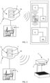
Figure 1 is a schematic view of a control system, according to the invention, configured to control two tapping valves of a beverage dispenser; -
Figure 2 is a schematic view similar to the schematic view ofFigure 1 showing a beverage dispenser in which two dispensing valves are installed; -
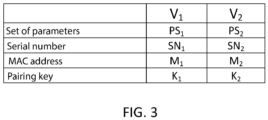
Figure 3 shows a table of data referring to each tapping valve. - In the various figures, similar parts will be indicated with the same reference numbers.
- With reference to
Figures 1-3 a control system according to the invention is disclosed - Said control system is configured to control one or more tapping valves installed on a beverage dispenser for tapping a respective beverage.
- In the embodiment being disclosed, the control system is configured to control one or more tapping valves of a plurality of tapping valves of a beverage dispenser, wherein said plurality of tapping valves comprises a first tapping valve V1 and a second tapping valve V2.
- The two tapping valves V1, V2 are installed on a beverage dispenser indicate with reference D.
- Consequently, it is possible to tap a first beverage, through the first tapping valve V1, and a second possible beverage, through the second tapping valve V2.
- Said first beverage and said second beverage can be different from each other or equal to each other.
- At least one first unique identification code is associated with the first tapping valve V1 and at least a second unique identification code is associated with the second tapping valve V2.
- In the embodiment being disclosed, two respective unique identification codes are associated with each tapping valve:
- a first unique identification code which a first serial number SN1 and a further first unique identification code which is a first MAC address M1 are associated with the first tapping valve V1;
- a second unique identification code which is a second serial number SN2 and a further second unique identification code which is a second MAC address M2 are associated with the second tapping valve V2.
- However, two identification codes associated with the same tapping valve are not necessary.
- It is sufficient that a single unique identification code is associated with each tapping valve and said unique identification code can be the serial number or the MAC address.
- With reference to the two tapping valves V1, V2 mentioned above, the control system allows to give a first command to the first tapping valve V1 and/or to control a first set of parameters PS1 associated with said first tapping valve V1, or to give a second command to the second tapping valve V2 and/or to control a second set of parameters PS2 associated with said second tapping valve V2.
- With reference to the first command, said first command causes the execution of an action performed by the first tapping valve V1, such as the opening or closing of said first tapping valve V1.
- With reference to the parameters of the first set of parameters PS1, said parameters relate to the first beverage to be dispensed through the first tapping valve V1 and can be for example: a numerical value associated with a quantity of a first liquid, wherein said first liquid is water or soda, a numerical value associated with a quantity of a second liquid, wherein said second liquid is a syrup, to be mixed with said quantity of said first liquid to form said first beverage (when the first beverage is obtained through a mixture of liquids), a numerical value associated with the ratio between said quantity of said first liquid and said quantity of said second liquid, a numerical value associated with the opening time of said first tapping valve V1, a numerical value associated with the closing time of said first tapping valve V1, a numeric value associated with the time interval in which said first tapping valve V1 is to be kept open, a numerical value associated with the time interval wherein said first tapping valve V1 is to be kept closed, etc..
- With reference to the second command, said second command causes the execution of an action performed by the second tapping valve V2, such as the opening or closing of said second tapping valve V2.
- With reference to the parameters of the second set of parameters PS2, said parameters relates to the second beverage to be dispensed through the second tapping valve V2 and can be for example: a numerical value associated with a quantity of a further first liquid, wherein said further first liquid is water or soda, a numerical value associated with a quantity of a further second liquid, wherein said further second liquid is a syrup, to be mixed with said quantity of said further first liquid to form said second beverage (when the second beverage is obtained through a mixture of liquids), a numerical value associated with the ratio between said quantity of said further first liquid and said quantity of said further second liquid, a numerical value associated with the opening time of said second tapping valve V2, a numerical value associated with the closing time of said second tapping valve V2, a numerical value associated with the time interval in which said second tapping valve V2 is to be kept open, a numerical value associated with the time interval in which said second tapping valve V2 is to be kept closed, etc..
- Although not shown in Figures, said control system can be configured to control a number of tapping valves greater than two, without departing from the scope of invention.
- With reference to the beverage dispenser D, said beverage dispenser D can be placed in any geographical area in the world and, in particular, in any site within said geographical area.
- Said site can be a bar or any environment in which a beverage dispenser D can be placed.
- With reference to the beverage dispenser D, said tapping valve V2 is connected or connectable to said first tapping valve V1.
- Each tapping valve V1, V2 comprises a respective control logic unit U1, U2 and respective storage means SM1, SM2.
- Said control system further comprises a telematic communication network C to send a control signal and a selecting and connecting electronic device G called gateway for selecting the first tapping valve V1 or the second tapping valve V2 and for connecting the telematics communication network C to the selected tapping valve (i.e. the tapping valve intended to receive the control signal).
- With reference to the telematic communication network C, said telematic communication network C comprises a cloud server SC, a control logic unit U and storage means SM.
- Said at least one unique identification code associated with the first tapping valve V1 and said at least a second unique identification code associated with the second tapping valve V2 are stored in said in said storage means SM.
- The control logic unit U of the cloud server SC is configured to:
- ∘ send a control signal to said first tapping valve V1 or to said second tapping valve V2 through said gateway G.
- Said control signal contains:
- a data packet comprising the following data:
at least one data referred to said first unique identification code, ore or more data of the following data group: a first command for the first tapping valve V1, one or more data referred to respective parameters to be modified, one or more data referred to respective further parameter to be added to said first set of parameters SP1 (when the control signal is directed to the first tapping valve V1), or - a further data packet comprising the following data:
at least one data referred to said second unique identification code, one or more data of the following data group: a data referred to a second command for the second tapping valve V2, one or more data referred to respective parameters to be modified, one or more data referred to respective further parameters to be added to said second set of parameters SP2 (when the control signal is directed to the second tapping valve V2). - The control logic unit U of said cloud server SC is configured to send a control signal (only) to said gateway G, irrespective of whether said control signal is directed to the first tapping valve V1 or to the second tapping valve V2.
- With reference to the gateway G, said gateway G comprises a further control logic unit UG configured to:
- ∘ verify if said control signal is directed to said first tapping valve V1 through said first unique identification code or to said second tapping valve V2 through said second unique identification code, and
- ∘ forward said control signal to said first tapping valve V1 or to said second tapping valve V2 based on the outcome of the verification of the unique identification code.
- The first control logic unit U1 of the first tapping valve V1 is configured to:
- ∘ receive the control signal sent by the control logic unit U of said cloud server SC through said gateway G, and
- ∘ perform said first command and/or modify one or more parameters of the first set of parameters PS1 and/or add one or more further parameters to said first set of parameters PS1.
- The second control logic unit U2 of the second tapping valve V2 is configured to:
- ∘ receive said control signal sent by the control logic unit U of said cloud server SC through said gateway G, and
- ∘ perform said second command and/or modify one or more parameters of the second set of parameters PS2 and/or add one or more further parameters to said second set of parameters PS2.
- Advantageously, the control system, object of the invention, allows an operator P to remotely connect (via said telematic communication network C) to the tapping valves V1, V2 of the beverage dispenser D to control each of said tapping valves independently of each other, without the need for said operator P to be in the same site where the beverage dispenser D is placed.
- Regardless of whether the control signal sent by the cloud server SC is directed to the first tapping valve V1 or to the second tapping valve V2, said control signal reaches the gateway G.
- The further control logic unit of the gateway G verifies to which tapping valve said control signal is directed and forwards said control signal to the tapping valve which is intended to receive the control signal.
- In the embodiment being disclosed, said gateway G is installed on said first tapping valve V1.
- Consequently, said first tapping valve V1 is a primary tapping valve or master tapping valve and the second tapping valve V2 is a secondary tapping valve or a slave tapping valve.
- In fact, the second tapping valve V2 is a tapping valve controlled by the first tapping valve V1 according to the information contained in the control signal sent by the cloud server SC to the gateway G and directed to the second tapping valve V2.
- In order to establish a connection between each tapping valve V1, V2 and the gateway G, a first pairing key K1 and a second pairing key K2, different from said first pairing key K1, are stored in the storage means SM of the cloud server SC.
- The first pairing key K1 serves to establish a connection between the first tapping valve V1 and gateway G and the second pairing key K2 serves to establish a connection between the second tapping valve V2 and gateway G.
- Said gateway G comprises further storage means SMG and said further control logic unit UG of said gateway G is configured to:
- ∘ send a request signal to said cloud server SC to obtain said first pairing key K1 and said second pairing key K2,
- ∘ receive a request signal sent from said cloud server SC, wherein said request signal contains said first pairing key K1 and said second pairing key K2,
- ∘ establish a connection between said gateway G and the first control logic unit U1 of the first tapping valve V1 through said first pairing key K1 and establish a connection between said gateway G and the second control logic unit U2 of the second tapping valve V2 through said second pairing key K2.
- Said control logic unit U of said cloud server SC is configured to:
- ∘ receive said request signal sent from said gateway G,
- ∘ send to said gateway G said request signal containing said first pairing key K1 and said second pairing key K2.
- In view of the above, the control system is designed in such a way that the control logic unit U of the cloud server SC is configured to send control signals and response signals to the gateway G, which, as mentioned, in the form of embodiment being described, is arranged in the first tapping valve V1.
- In the embodiment being disclosed, the connection between said gateway G and said first tapping valve V1 and the connection between said gateway G and said second tapping valve V2 are wireless connections.
- In particular, each wireless connection is a bluetooth connection.
- Furthermore, said further control logic unit UG of said gateway G is configured to store in said further storage means SMG the data of said data packet and the data of said further data packet, when it receives said control signal from said cloud server SC.
- With reference to the first tapping valve V1, a first unlock code can be stored in said first storage means SM1 of said first tapping valve V1.
- Said first unlock code serves to enable said first tapping valve V1 to receive one or more predetermined first commands from said cloud server SC.
- With reference to the second tapping valve V2, a second unlock code can be stored in said second storage means SM2 of said second tapping valve V2.
- Said second unlock code serves to enable said second tapping valve V2 to receive one or more predetermined second commands from said cloud server SC.
- In one example, the typing of the first unlock code by an operator at the site where the beverage dispenser D is placed can enable the first tapping valve V1 to receive a control signal sent by the cloud server SC so that the first tapping valve V1 dispenses the first beverage B1.
- In said example, the predetermined command performed by the first tapping valve V1 is the dispensing of the first beverage B1.
- However, the predetermined command can be different from the dispensing of the first beverage.
- The same considerations can be applied to the second tapping valve V2 and to the second unlock code.
- Furthermore, said control signal is an encrypted signal.
- A first decryption key for decrypting said control signal is stored in the first storage means SM1 of the first tapping valve V1, and a second decryption key for decrypting said control signal, different from said first decryption key, is stored in the second storage means SM2 of the second tapping valve V2.
- Said first decryption key and said second decryption key are also stored in the storage means SM of the cloud server SC.
- The first control logic unit U1 of the first tapping valve V1 is configured to decrypt said control signal by means of said first decryption key (when the control signal is directed to the first tapping valve V1).
- The second control logic unit U2 of the second tapping valve V2 is configured to decrypt said control signal by means of said second decryption key (when the control signal is directed to the second tapping valve V2).
- A digital twin associated with said beverage dispenser D can be stored in said storage means SM of said cloud server SC.
- The expression "digital twin" means a virtual representation of a physical entity or a process.
- In the specific case, the expression "digital twin" means the virtual representation of a physical entity that is the beverage dispenser.
- The present invention also relates to a method for creating a digital twin associated with a beverage dispenser D comprising a control system mentioned above.
- The method for creating a digital twin associated with a beverage dispenser D comprises the following steps:
- A) storing in said storage means SM the following data:
- one or more geographical areas A1,A2... AN (wherein N is a positive integer number),
- for each geographical area A1,A2...AN one or more respective sites S11,S12...S1M; S21,S22...S2M; SN1,SN2...SNM)in which at least a beverage dispenser D is placed, and
- a plurality of beverages B1,B2...BJ (wherein J is a positive integer number), different from each other;
- B) selecting:
- a geographical area between the geographical areas A1,A2... AN stored in said storage means SM and/or a site between the sites S11,S12...S1M; S21,S22...S2M; SN1,SN2... SNM stored in said storage means SM associated with the selected geographical area, and
- storing in said storage means SM a data concerning said selected geographical area A1,A2... AN and/or a data concerning said selected site S11,S12...S1M, S21,S22...S2M; SN1,SN2...SNM,
- C) selecting a first beverage B1 between said plurality of beverages B1,B2...BJ;
- D) associating said first beverage B1 with said first tapping valve V1 and storing in said storage means SM a data concerning said first beverage B1 associated with said first tapping valve V1;
- E) selecting a second beverage B2 between said plurality of beverages B1,B2...BJ;
- F) associating said second beverage B2 with said second tapping valve V2 and storing in said storage means SM a data concerning said second beverage B2 associated with said second tapping valve V2; and
- G) creating a digital twin associated with said beverage dispenser D through a data group stored in said storage means SM, wherein said data group comprises:
- a data concerning said selected geographical area A1,A2...AN and/or a data concerning said selected site S11,S12...S1M; S21,S22... S2M; SN1,SN2...SNM,
- a data concerning said at least one a first unique identification code associated with said first tapping valve V1,
- a data concerning said at least one second unique identification code associated with said second tapping valve V2,
- a data concerning said first beverage B1 associated with said first tapping valve V1, and
- a data concerning said second beverage B2 associated with said second tapping valve V2.
- Furthermore, the step A can comprises the following sub-step:
A1) storing in said storage means SM a number equal to the total number of tapping valves included in said beverage dispenser D. - If the step A of the method comprises the sub-step A1, the data group mentioned in step G can comprise said total number of tapping valves.
- With reference to step A, a plurality of sets of parameters are stored in said storage means SM.
- Said plurality of sets of parameters comprises at least one first set of parameters associated with the first beverage B1 comprising one or more parameters, and a second set of parameters associated with the second beverage B2 comprising one or more parameters.
- With reference to step C of the method, said step G can comprise the sub-step of selecting said first set of parameters associated with the first beverage B1, and with reference to the step E of the method, said step E can comprise the sub-step of selecting said second set of parameters associated with the second beverage B2.
- Furthermore, said method can comprise the following steps: modifying one or more parameters of said first set of parameters stored in said storage means SM, so that said one or more modified parameters of said first set of parameters are stored in said storage means SM,
and/or
modifying one or more parameters of said second set of parameters stored in said storage means SM, so that said one or more modified parameters of said second set of parameters are stored in said storage means SM. - With reference to step G, said data group can comprise said one or more modified parameters of said first set of parameters and/or said one or more modified parameters of said second set of parameters.
- Said cloud server SC can comprise a control logic unit U connected to said storage means SM and configured to:
- ∘ modifying said one or more parameters of said first set of parameters, and/or
- ∘ modifying said one or more parameters of said second set of parameters.
- Advantageously, the control system object of the invention allows to control one or more tapping valves of a beverage dispenser by means of a simple structure and ensuring a secure exchange of information between the telematic communication network and said one or more tapping valves.
- The present invention has been described for illustrative, but not limitative purposes, according to its preferred embodiment, but it is to be understood that variations and/or modifications can be carried out by a skilled in the art, without departing from the scope thereof, as defined according to enclosed claims.
Claims (14)
- Control system for controlling one or more tapping valves included in a beverage dispenser (D), wherein said beverage dispenser (D) is of the type comprising a plurality of tapping valves comprising at least one first tapping valve (V1) and a second tapping valve (V2), wherein said first tapping valve (V1) comprises a first control logic unit (U1) and first storage means (SM1) in which at least one unique identification code associated with said first tapping valve (V1) and a first set of parameters (PS1) are stored, and said second tapping valve (V2) comprises a second control logic unit (U2) and second storage means (SM2) in which at least one second unique identification code associated with said second tapping valve (V2) and a second set of parameters (PS2), said control system comprising:- a telematic communication network (C) comprising a cloud server (SC) comprising in turn a control logic unit (U) and storage means (SM) in which at least one said first unique identification code and said second unique identification code are stored,- a selecting and connecting electronic device (G) called gateway, for selecting said first tapping valve (V1) or said second tapping valve (V2) and connecting said telematics communication network (C) to said first tapping valve (V1) or to said second tapping valve (V2),whereinthe control logic unit (U) of said cloud server (SC) is configured to:∘ send a control signal to said gateway (G), regardless of whether said control signal is directed to said first tapping valve (V1) or to said second tapping valve (V2), wherein said control signal contains:a data packet comprising the following data:
at least one data referred to said first unique identification code, one or more data of the following data group: a first command for the first tapping valve (V1), one or more data referred to respective parameters to be modified, one or more data referred to respective further parameters to be added to said first set of parameters (SP1), ora further data packet comprising the following data:
at least one data referred to said second unique identification code, one or more data of the following data group:
a data referred to a second command for the second tapping valve (V2), one or more data referred to respective parameters to be modified, one or more data referred to respective further parameters to be added to said second set of parameters (SP2),said gateway (G) comprises a further control logic unit (UG) configured to:∘ verify if said control signal is directed to said first tapping valve (V1) through said first unique identification code or to said second tapping valve (V2) through said second unique identification code, and∘ forward said control signal to said first tapping valve (V1) or to said second tapping valve (V2) based on the outcome of the verification of the unique identification code,the first control logic unit (U1) of said first tapping valve (V1) is configured to:∘ receive said control signal sent by the control logic unit (U) of said cloud server (SC) through said gateway (G), and∘ perform said first command and/or modify one or more parameters of the first set of parameters (PS1) and/or add one or more further parameters to said first set of parameters (PS1);the second control logic unit (U2) of said second tapping valve (V2) is configured to:∘ receive said control signal sent by the control logic unit (U) of said cloud server (SC) through said gateway (G), and∘ perform said second command and/or modify one or more parameters of the second set of parameters (PS2) and/or add one or more further parameters to said second set of parameters (PS2). - Control system according to the previous claim, whereina first pairing key (K1) and a second pairing key (K2) are stored in said storage means (SM) of said cloud server (SC),whereinsaid gateway (G) comprising further storage means (SMG) and said further control logic unit (UG) of said gateway (G) is configured to:∘ send a request signal to said cloud server(SC) to obtain said first pairing key (K1) and said second pairing key (K2),∘ receive a request signal sent from said cloud server (SC), wherein said request signal contains said first pairing key (K1) and said second pairing key (K2),∘ establish a connection between said gateway (G) and the first control logic unit (U1) of the first tapping valve (V1) through said first pairing key (K1) and establish a connection between said gateway (G) and the second control logic unit (U2) of the second tapping valve (V2) through said second pairing key (K2),said control logic unit (U) of said cloud server (SC) is configured to:∘ receive said request signal sent from said gateway (G),∘ send to said gateway (G) said request signal containing said first pairing key (K1) and said second pairing key (K2).
- Control system according to any one of the previous claims, wherein said connection between said gateway (G) and said first tapping valve (V1) is a wireless connection, preferably bluetooth, and the connection between said gateway (G) and said second tapping valve (V2) is a wireless connection, preferably bluetooth.
- Control system according to claim 2 or 3, wherein said further control logic unit (UG) of said gateway (G) is configured to store in said further storage means (SMc) the data of said data packet and the data of said further data packet, when it receives said control signal sent from said cloud server (SC).
- Control system according to any one of the previous claims, wherein a first unlock code is stored in said first storage means (SM1) of said first tapping valve (V1), said first unlock code serving to enable said first tapping valve (V1) to receive one or more predetermined first commands from said cloud server (SC),
wherein
a second unlock code is stored in said second storage means (SM2) of said second tapping valve (V2), said second unlock code serving to enable said second tapping valve (V2) to receive one or more predetermined second commands from said cloud server (SC). - Control system according to any one of the previous claims, wherein said first unique identification code is a first serial number (SN1) or a first MAC address (M1) and said second unique identification code is a second serial number (SN2) or a second MAC address (M2).
- Control system according to any one of the previous claims, wherein said gateway (G) is installed on said first tapping valve (V1).
- Control system according to any one of the previous claims, wherein said control signal is an encrypted signal,a first decryption key for decrypting said control signal is stored in said first storage means (SM1),a second decryption key for decrypting said control signal, different from said first decryption key, is stored in said second storage means (SM2), said first decryption key and said second decryption key are stored in said storage means (SM) of said cloud server (SC),whereinsaid first control logic unit (U1) of said first tapping valve (V1) is configured to decrypt said control signal through said first decrypting key, when said control signal is directed to the first tapping valve (V1), andsaid second control logic unit (U2) of said second tapping valve (V2) is configured to decrypt said control signal through said second decrypting key, when said control signal is directed to the second tapping valve (V2).
- Control system according to any one of the previous claims, wherein a digital twin associated with said beverage dispenser (D) is stored in said storage means (SM) of said cloud server (SC).
- Method for creating a digital twin associated with a beverage dispenser (D), wherein said beverage dispenser (D) comprises a control system according to claim 9, said method comprising the following steps:A) storing in said storage means (SM) the following data:one or more geographical areas (A1,A2...AN),for each geographical area (A1,A2...AN) one or more respective sites (S11,S12...S1M; S21,S22...S2M; SN1,SN2...SNM) in which at least a beverage dispenser (D) is placed, anda plurality of beverage (B1,B2...BJ), different from each other;B) selecting:a geographical area between the geographical areas (A1,A2...AN) stored in said storage means (SM) and/or a site between the sites (S11,S12...S1M; S21,S22...S2M; SN1,SN2...SNM) stored in said storage means (SM) associated with the selected geographical area, andstoring in said storage means (SM) a data concerning said selected geographical area (A1,A2...AN) and/or a data concerning said selected site (S11,S12...S1M; S21,S22...S2M; SN1,SN2...SNM);C) selecting a first beverage (B1) between said plurality of beverages (B1,B2... BJ);D) associating said first beverage (B1) with said first tapping valve (V1) and storing in said storage means (SM) a data concerning said first beverage (B1) associated with said first tapping valve (V1);E) selecting a second beverage (B2) between said plurality of beverages (B1,B2...BJ);F) associating said second beverage (B2) with said second tapping valve (V2) and storing in said storage means (SM) a data concerning said second beverage (B2) associated with said second tapping valve (V2); andG) creating a digital twin of said beverage dispenser (D) through a data group stored in said storage means (SM), wherein said data group comprises:a data concerning said selected geographical area (A1,A2...AN) and/or a data concerning said selected site (S11,S12...S1M; S21,S22...S2M; SN1,SN2...SNM),a data concerning said at least one a first unique identification code associated with said first tapping valve (V1),a data concerning said at least one second unique identification code associated with said second tapping valve (V2),a data concerning said first beverage (B1) associated with said first tapping valve (V1), anda data concerning said second beverage (B2) associated with said second tapping valve (V2).
- Method according to the previous claim, wherein
the step A comprises the following sub-step:A1) storing in said storage means (SM) a number equal to the total number of tapping valves included in said beverage dispenser (D),whereinwith the reference to the step G, said data group comprises said total number of tapping valves. - Method according to any one of claims 10-11, wherein
with reference to the step A, a plurality of sets of parameters are stored in said storage means (SM), wherein said plurality of sets of parameters comprises at least one first set of parameters associated with the first beverage (B1) comprising one or more parameters, and a second set of parameters associated with the second beverage (B2) comprising one or more parameters. - Method according to the previous claim, wherein
said step C comprises the following sub-step:
selecting said first set of parameters associated with the first beverage (B1), said step E comprises the following sub-step:selecting said second set of parameters associated with the second beverage (B2),whereinsaid method comprises the following steps:modifying one or more parameters of said first set of parameters stored in said storage means (SM), so that said one or more modified parameters of said first set of parameters are stored in said storage means (SM),
and/ormodifying one or more parameters of said second set of parameters stored in said storage means (SM), so that said one or more modified parameters of said second set of parameters are stored in said storage means (SM),whereinwith reference to the step G, said data group comprises said one or more modified parameters of said first set of parameters and/or said one or more modified parameters of said second set of parameters. - Method according to the previous claim, wherein said cloud server (SC) comprises a control logic unit (U) connected to said storage means (SM) and configured to:∘ modifying said one or more parameters of said first set of parameters, and/or∘ modifying said one or more parameters of said second set of parameters.
Applications Claiming Priority (1)
| Application Number | Priority Date | Filing Date | Title |
|---|---|---|---|
| IT102021000033128A IT202100033128A1 (en) | 2021-12-30 | 2021-12-30 | Control system for controlling one or more tap valves of a beverage dispenser |
Publications (3)
| Publication Number | Publication Date |
|---|---|
| EP4206925A1 true EP4206925A1 (en) | 2023-07-05 |
| EP4206925B1 EP4206925B1 (en) | 2025-04-09 |
| EP4206925C0 EP4206925C0 (en) | 2025-04-09 |
Family
ID=80685145
Family Applications (1)
| Application Number | Title | Priority Date | Filing Date |
|---|---|---|---|
| EP22217010.2A Active EP4206925B1 (en) | 2021-12-30 | 2022-12-28 | Control system for controlling one or more tapping valves of a beverage dispenser |
Country Status (3)
| Country | Link |
|---|---|
| US (1) | US12541185B2 (en) |
| EP (1) | EP4206925B1 (en) |
| IT (1) | IT202100033128A1 (en) |
Citations (5)
| Publication number | Priority date | Publication date | Assignee | Title |
|---|---|---|---|---|
| EP3248933A1 (en) * | 2014-11-03 | 2017-11-29 | Pernod Ricard SA | Beverage dispensing apparatus and method |
| US20190012498A1 (en) * | 2017-07-07 | 2019-01-10 | Instream Water, Inc. | Beverage kiosk apparatus, system, and method |
| US20200249660A1 (en) * | 2019-02-01 | 2020-08-06 | L2F Inc. | Integrated front-of-house and back-of-house restaurant automation system |
| US20210221667A1 (en) * | 2020-01-16 | 2021-07-22 | Starbucks Corporation | Automated dispensing system for customized beverages |
| WO2021211798A1 (en) * | 2020-04-16 | 2021-10-21 | View, Inc. | Interaction between an enclosure and one or more occupants |
Family Cites Families (5)
| Publication number | Priority date | Publication date | Assignee | Title |
|---|---|---|---|---|
| US9762563B2 (en) * | 2015-10-14 | 2017-09-12 | FullArmor Corporation | Resource access system and method |
| US11713234B2 (en) * | 2018-07-06 | 2023-08-01 | The Coca-Cola Company | Beverage dispenser network and profile management |
| US11815922B2 (en) * | 2019-10-11 | 2023-11-14 | Schlumberger Technology Corporation | Multiple valve control system and method |
| WO2021078980A1 (en) * | 2019-10-24 | 2021-04-29 | The Magic Of Things Ltd | Control device for enabling rf control in a user environment |
| US20210362993A1 (en) * | 2020-05-19 | 2021-11-25 | Smart Soda Holdings, Inc. | Touch-less beverage dispenser |
-
2021
- 2021-12-30 IT IT102021000033128A patent/IT202100033128A1/en unknown
-
2022
- 2022-12-28 EP EP22217010.2A patent/EP4206925B1/en active Active
- 2022-12-28 US US18/147,273 patent/US12541185B2/en active Active
Patent Citations (5)
| Publication number | Priority date | Publication date | Assignee | Title |
|---|---|---|---|---|
| EP3248933A1 (en) * | 2014-11-03 | 2017-11-29 | Pernod Ricard SA | Beverage dispensing apparatus and method |
| US20190012498A1 (en) * | 2017-07-07 | 2019-01-10 | Instream Water, Inc. | Beverage kiosk apparatus, system, and method |
| US20200249660A1 (en) * | 2019-02-01 | 2020-08-06 | L2F Inc. | Integrated front-of-house and back-of-house restaurant automation system |
| US20210221667A1 (en) * | 2020-01-16 | 2021-07-22 | Starbucks Corporation | Automated dispensing system for customized beverages |
| WO2021211798A1 (en) * | 2020-04-16 | 2021-10-21 | View, Inc. | Interaction between an enclosure and one or more occupants |
Also Published As
| Publication number | Publication date |
|---|---|
| US20230213910A1 (en) | 2023-07-06 |
| US12541185B2 (en) | 2026-02-03 |
| EP4206925B1 (en) | 2025-04-09 |
| EP4206925C0 (en) | 2025-04-09 |
| IT202100033128A1 (en) | 2023-06-30 |
Similar Documents
| Publication | Publication Date | Title |
|---|---|---|
| US11059713B1 (en) | Remote beverage selection with a beverage dispenser | |
| EP2077684A2 (en) | Methods of and systems for offering and/or providing information | |
| KR0155373B1 (en) | Public communication system | |
| EP3164857B1 (en) | System and method for the remote control of the shared access to one or more items | |
| US12541185B2 (en) | Control system for controlling one or more tapping valves of a beverage dispenser | |
| CN101183466A (en) | System and method for group control of ticket checking equipment | |
| KR102178031B1 (en) | unmanned storage system based on user location | |
| US20110212686A1 (en) | System, method, service server, traffic information relay method, application server, mobile communication terminal, navigation terminal, execution method, and storage medium for providing traffic information using short-range communication network | |
| CN101577654B (en) | Digital home network system and automatic configuration method and input equipment thereof | |
| CN103139078A (en) | Relay server and relay communication system | |
| EP4206926A1 (en) | Method for creating a digital twin of a beverage dispenser | |
| US11470063B2 (en) | Vehicle configurable transmitter for allowing cloud-based transfer of data between vehicles | |
| CN101860851A (en) | Be used for the method that controlled access is included in the information of terminal | |
| JP3751584B2 (en) | CONTROL DISPLAY DEVICE, RECORDING MEDIUM CONTAINING THE PROGRAM, AND CONTROL SYSTEM | |
| JP3681577B2 (en) | Control display device and recording medium on which program is recorded | |
| US20230373775A1 (en) | Remote beverage selection with a beverage dispenser | |
| US20170161122A1 (en) | Method and device for implementing a transaction concept in opc ua by means of a timeout mechanism | |
| AU2021101316A4 (en) | A system for service providing using block-chain | |
| US20090093894A1 (en) | Production management system and method of controlling the same | |
| CN110536186A (en) | A kind of remote sensing control method, device, electronic equipment and storage medium | |
| JP2021051571A (en) | Vending machine system | |
| JP2682344B2 (en) | Multi-device system control method | |
| US20260136198A1 (en) | Method for safely operating at least one automation technology field device | |
| AU2021101231A4 (en) | A block-chain enabled service provider system | |
| JP4147351B2 (en) | Customer information management system and customer management center and electrical equipment used therefor |
Legal Events
| Date | Code | Title | Description |
|---|---|---|---|
| PUAI | Public reference made under article 153(3) epc to a published international application that has entered the european phase |
Free format text: ORIGINAL CODE: 0009012 |
|
| STAA | Information on the status of an ep patent application or granted ep patent |
Free format text: STATUS: THE APPLICATION HAS BEEN PUBLISHED |
|
| AK | Designated contracting states |
Kind code of ref document: A1 Designated state(s): AL AT BE BG CH CY CZ DE DK EE ES FI FR GB GR HR HU IE IS IT LI LT LU LV MC ME MK MT NL NO PL PT RO RS SE SI SK SM TR |
|
| STAA | Information on the status of an ep patent application or granted ep patent |
Free format text: STATUS: REQUEST FOR EXAMINATION WAS MADE |
|
| 17P | Request for examination filed |
Effective date: 20231227 |
|
| RBV | Designated contracting states (corrected) |
Designated state(s): AL AT BE BG CH CY CZ DE DK EE ES FI FR GB GR HR HU IE IS IT LI LT LU LV MC ME MK MT NL NO PL PT RO RS SE SI SK SM TR |
|
| STAA | Information on the status of an ep patent application or granted ep patent |
Free format text: STATUS: EXAMINATION IS IN PROGRESS |
|
| 17Q | First examination report despatched |
Effective date: 20240318 |
|
| GRAP | Despatch of communication of intention to grant a patent |
Free format text: ORIGINAL CODE: EPIDOSNIGR1 |
|
| STAA | Information on the status of an ep patent application or granted ep patent |
Free format text: STATUS: GRANT OF PATENT IS INTENDED |
|
| RIC1 | Information provided on ipc code assigned before grant |
Ipc: G06F 21/44 20130101ALN20241031BHEP Ipc: B67D 1/08 20060101ALI20241031BHEP Ipc: B67D 1/14 20060101ALI20241031BHEP Ipc: B67D 1/00 20060101ALI20241031BHEP Ipc: G06F 8/71 20180101ALI20241031BHEP Ipc: G06F 9/54 20060101AFI20241031BHEP |
|
| INTG | Intention to grant announced |
Effective date: 20241115 |
|
| GRAS | Grant fee paid |
Free format text: ORIGINAL CODE: EPIDOSNIGR3 |
|
| GRAA | (expected) grant |
Free format text: ORIGINAL CODE: 0009210 |
|
| STAA | Information on the status of an ep patent application or granted ep patent |
Free format text: STATUS: THE PATENT HAS BEEN GRANTED |
|
| AK | Designated contracting states |
Kind code of ref document: B1 Designated state(s): AL AT BE BG CH CY CZ DE DK EE ES FI FR GB GR HR HU IE IS IT LI LT LU LV MC ME MK MT NL NO PL PT RO RS SE SI SK SM TR |
|
| REG | Reference to a national code |
Ref country code: GB Ref legal event code: FG4D |
|
| REG | Reference to a national code |
Ref country code: CH Ref legal event code: EP |
|
| REG | Reference to a national code |
Ref country code: IE Ref legal event code: FG4D |
|
| U01 | Request for unitary effect filed |
Effective date: 20250410 |
|
| U07 | Unitary effect registered |
Designated state(s): AT BE BG DE DK EE FI FR IT LT LU LV MT NL PT RO SE SI Effective date: 20250417 |
|
| PG25 | Lapsed in a contracting state [announced via postgrant information from national office to epo] |
Ref country code: ES Free format text: LAPSE BECAUSE OF FAILURE TO SUBMIT A TRANSLATION OF THE DESCRIPTION OR TO PAY THE FEE WITHIN THE PRESCRIBED TIME-LIMIT Effective date: 20250409 |
|
| PG25 | Lapsed in a contracting state [announced via postgrant information from national office to epo] |
Ref country code: GR Free format text: LAPSE BECAUSE OF FAILURE TO SUBMIT A TRANSLATION OF THE DESCRIPTION OR TO PAY THE FEE WITHIN THE PRESCRIBED TIME-LIMIT Effective date: 20250710 Ref country code: NO Free format text: LAPSE BECAUSE OF FAILURE TO SUBMIT A TRANSLATION OF THE DESCRIPTION OR TO PAY THE FEE WITHIN THE PRESCRIBED TIME-LIMIT Effective date: 20250709 |
|
| PG25 | Lapsed in a contracting state [announced via postgrant information from national office to epo] |
Ref country code: PL Free format text: LAPSE BECAUSE OF FAILURE TO SUBMIT A TRANSLATION OF THE DESCRIPTION OR TO PAY THE FEE WITHIN THE PRESCRIBED TIME-LIMIT Effective date: 20250409 |
|
| PG25 | Lapsed in a contracting state [announced via postgrant information from national office to epo] |
Ref country code: HR Free format text: LAPSE BECAUSE OF FAILURE TO SUBMIT A TRANSLATION OF THE DESCRIPTION OR TO PAY THE FEE WITHIN THE PRESCRIBED TIME-LIMIT Effective date: 20250409 |
|
| PG25 | Lapsed in a contracting state [announced via postgrant information from national office to epo] |
Ref country code: RS Free format text: LAPSE BECAUSE OF FAILURE TO SUBMIT A TRANSLATION OF THE DESCRIPTION OR TO PAY THE FEE WITHIN THE PRESCRIBED TIME-LIMIT Effective date: 20250709 |
|
| PG25 | Lapsed in a contracting state [announced via postgrant information from national office to epo] |
Ref country code: IS Free format text: LAPSE BECAUSE OF FAILURE TO SUBMIT A TRANSLATION OF THE DESCRIPTION OR TO PAY THE FEE WITHIN THE PRESCRIBED TIME-LIMIT Effective date: 20250809 |
|
| U20 | Renewal fee for the european patent with unitary effect paid |
Year of fee payment: 4 Effective date: 20251006 |
|
| PG25 | Lapsed in a contracting state [announced via postgrant information from national office to epo] |
Ref country code: SM Free format text: LAPSE BECAUSE OF FAILURE TO SUBMIT A TRANSLATION OF THE DESCRIPTION OR TO PAY THE FEE WITHIN THE PRESCRIBED TIME-LIMIT Effective date: 20250409 |
|
| PG25 | Lapsed in a contracting state [announced via postgrant information from national office to epo] |
Ref country code: CZ Free format text: LAPSE BECAUSE OF FAILURE TO SUBMIT A TRANSLATION OF THE DESCRIPTION OR TO PAY THE FEE WITHIN THE PRESCRIBED TIME-LIMIT Effective date: 20250409 |
|
| PG25 | Lapsed in a contracting state [announced via postgrant information from national office to epo] |
Ref country code: SK Free format text: LAPSE BECAUSE OF FAILURE TO SUBMIT A TRANSLATION OF THE DESCRIPTION OR TO PAY THE FEE WITHIN THE PRESCRIBED TIME-LIMIT Effective date: 20250409 |
|
| PLBE | No opposition filed within time limit |
Free format text: ORIGINAL CODE: 0009261 |
|
| STAA | Information on the status of an ep patent application or granted ep patent |
Free format text: STATUS: NO OPPOSITION FILED WITHIN TIME LIMIT |
|
| REG | Reference to a national code |
Ref country code: CH Ref legal event code: L10 Free format text: ST27 STATUS EVENT CODE: U-0-0-L10-L00 (AS PROVIDED BY THE NATIONAL OFFICE) Effective date: 20260218 |
|
| 26N | No opposition filed |
Effective date: 20260112 |