EP4206874A1 - Stylus storage apparatus and method, and electronic device - Google Patents
Stylus storage apparatus and method, and electronic device Download PDFInfo
- Publication number
- EP4206874A1 EP4206874A1 EP22871046.3A EP22871046A EP4206874A1 EP 4206874 A1 EP4206874 A1 EP 4206874A1 EP 22871046 A EP22871046 A EP 22871046A EP 4206874 A1 EP4206874 A1 EP 4206874A1
- Authority
- EP
- European Patent Office
- Prior art keywords
- stylus
- coil part
- ejection mechanism
- accommodating space
- receiving apparatus
- Prior art date
- Legal status (The legal status is an assumption and is not a legal conclusion. Google has not performed a legal analysis and makes no representation as to the accuracy of the status listed.)
- Granted
Links
Images


Classifications
-
- G—PHYSICS
- G06—COMPUTING OR CALCULATING; COUNTING
- G06F—ELECTRIC DIGITAL DATA PROCESSING
- G06F1/00—Details not covered by groups G06F3/00 - G06F13/00 and G06F21/00
- G06F1/16—Constructional details or arrangements
- G06F1/1601—Constructional details related to the housing of computer displays, e.g. of CRT monitors, of flat displays
- G06F1/1607—Arrangements to support accessories mechanically attached to the display housing
-
- G—PHYSICS
- G06—COMPUTING OR CALCULATING; COUNTING
- G06F—ELECTRIC DIGITAL DATA PROCESSING
- G06F3/00—Input arrangements for transferring data to be processed into a form capable of being handled by the computer; Output arrangements for transferring data from processing unit to output unit, e.g. interface arrangements
- G06F3/01—Input arrangements or combined input and output arrangements for interaction between user and computer
- G06F3/03—Arrangements for converting the position or the displacement of a member into a coded form
- G06F3/033—Pointing devices displaced or positioned by the user, e.g. mice, trackballs, pens or joysticks; Accessories therefor
- G06F3/0354—Pointing devices displaced or positioned by the user, e.g. mice, trackballs, pens or joysticks; Accessories therefor with detection of two-dimensional [2D] relative movements between the device, or an operating part thereof, and a plane or surface, e.g. 2D mice, trackballs, pens or pucks
- G06F3/03545—Pens or stylus
-
- G—PHYSICS
- G06—COMPUTING OR CALCULATING; COUNTING
- G06F—ELECTRIC DIGITAL DATA PROCESSING
- G06F1/00—Details not covered by groups G06F3/00 - G06F13/00 and G06F21/00
- G06F1/16—Constructional details or arrangements
- G06F1/1613—Constructional details or arrangements for portable computers
-
- H—ELECTRICITY
- H04—ELECTRIC COMMUNICATION TECHNIQUE
- H04M—TELEPHONIC COMMUNICATION
- H04M1/00—Substation equipment, e.g. for use by subscribers
- H04M1/02—Constructional features of telephone sets
- H04M1/21—Combinations with auxiliary equipment, e.g. with clocks or memoranda pads
-
- G—PHYSICS
- G06—COMPUTING OR CALCULATING; COUNTING
- G06F—ELECTRIC DIGITAL DATA PROCESSING
- G06F2200/00—Indexing scheme relating to G06F1/04 - G06F1/32
- G06F2200/16—Indexing scheme relating to G06F1/16 - G06F1/18
- G06F2200/163—Indexing scheme relating to constructional details of the computer
- G06F2200/1632—Pen holder integrated in the computer
Definitions
- This application relates to the field of electronic devices, and in particular, to a stylus receiving apparatus, a method, and an electronic device.
- Some electronic devices such as a mobile phone and a tablet computer, are often used to cooperate with a stylus.
- a receiving structure used to receive the stylus may be disposed on these electronic devices.
- This application provides a stylus receiving apparatus, a method, and an electronic device, to resolve problems of receiving a stylus in an existing electronic device and a relatively poor hand feeling.
- an embodiment of this application provides a stylus receiving apparatus, including a bracket, an ejection mechanism, a holding assembly, and a sensing assembly.
- the bracket defines an accommodating space, and the accommodating space has an exit/entrance port for inserting a stylus.
- the ejection mechanism is disposed in the accommodating space, and the ejection mechanism can be driven to a locked state or an unlocked state by the stylus that is inserted into the accommodating space. In the locked state, the ejection mechanism allows the stylus to be received in the accommodating space. In the unlocked state, the ejection mechanism is capable of ejecting the stylus from the accommodating space.
- the holding assembly is configured to cooperate with a held element on the stylus, so as to hold the stylus.
- the holding assembly includes a magnet part and a coil part.
- the holding assembly generates a first magnetic field when the coil part is powered off.
- the holding assembly generates a second magnetic field when the coil part is powered on.
- a holding force exerted by the second magnetic field on the stylus is smaller than a holding force exerted by the first magnetic field on the stylus.
- the sensing assembly is communicatively connected to the coil part.
- the sensing assembly senses a state change of the ejection mechanism by sensing movement of the ejection mechanism.
- the coil part is powered off when the sensing assembly senses that the ejection mechanism changes from an unlocked state to a locked state.
- the coil part is powered on when the sensing assembly senses that the ejection mechanism changes from the locked state to the unlocked state.
- the stylus receiving apparatus in this embodiment of this application has beneficial effects of reliably holding the stylus, pressing and taking out the stylus with less force, better hand feeling, and better user experience.
- the magnet part is in a shape of an arc ring, and the arc ring has an inner circumferential surface and an outer circumferential surface that are radially opposite, a first axial end surface and a second axial end surface that are axially opposite, and a first arc end surface and a second arc end surface that are archwise opposite.
- the first axial end surface, the first arc end surface, the second axial end surface, and the second arc end surface are sequentially connected end-to-end to form a closed loop.
- the coil part is formed by winding a wire around the magnet part along the closed loop, and the coil part can be powered on to generate a magnetic field opposite to a magnetic field of the magnet part.
- the holding assembly that integrates a magnet part and a coil part is formed by winding a wire around the magnet part along the closed loop.
- a magnetic field distribution when the coil part is powered on and a magnetic field distribution of the magnet part are basically consistent with each other, and it is easy to control the overall magnetic field of the holding assembly through inverse superposition of magnetic fields of the coil part and the magnet part, so as to reliably control a holding force.
- the coil part is defined between an inner circumferential surface and an outer circumferential surface of the arc ring.
- a winding range of the coil part is located between the inner circumferential surface and the outer circumferential surface of the arc ring, so that winding of the coil part does not increase a thickness (that is, spacing between the inner circumferential surface and the outer circumferential surface) of the magnet part, thereby facilitating mounting of the holding assembly and reducing required mounting space.
- the plurality of holding assemblies are distributed along a circumferential direction, and are enclosed into a ring that communicates with the accommodating space in an axial direction, to allow the stylus to penetrate.
- a plurality of holding assemblies are enclosed into a ring, so that the stylus can be held from each direction, thereby improving holding reliability.
- the coil part in each direction also generate a corresponding reverse magnetic field when the coil part is powered on, to offset at least a part of a holding force of the magnet part, so as to help eject the stylus.
- the sensing assembly includes a magnetic member and a Hall element.
- the magnetic member is disposed in the ejection mechanism, and can be displaced with a change of the ejection mechanism between a locked state and an unlocked state.
- the Hall element and the bracket are relatively fastened, and can sense displacement of the magnetic member.
- a state change of the ejection mechanism is determined based on movement that is of the magnetic element with the ejection mechanism and that is sensed by the Hall element, and the coil part is controlled to be powered on or powered off, so that the stylus can be easily held firmly when being received, and a holding force when the stylus is ejected can be easily reduced.
- the stylus receiving apparatus further includes a power supply apparatus, configured to supply power to the coil part and/or the sensing assembly.
- a power supply mode of the power supply apparatus is battery power supply or wireless power supply.
- power supply can be implemented by additionally providing a battery for the stylus receiving apparatus or in a wireless manner (for example, a primary power supply that may come from an electronic device), so as to supply power to each power consumption structure of the apparatus.
- the bracket includes a seat frame and a cover, and the cover is detachably connected to the seat frame, to enclose into the accommodating space; and when the cover is detached from the seat frame, the accommodating space is opened.
- the detachable seat frame and the detachable cover are disposed, so as to facilitate operations such as disassembly/assembly and replacement of an internal structure of the bracket.
- there are two holding assemblies and both are in a shape of a semicircular ring; and one of the two holding assemblies is connected to the seat frame, and the other is connected to the cover; and when the cover and the seat frame are combined, the two holding assemblies are enclosed into a ring that communicates with the accommodating space in an axial direction, to allow the stylus to penetrate.
- the two holding assemblies are separately mounted on the seat frame and the cover, and are enclosed into a ring that communicates with the accommodating space, to allow the stylus to penetrate, and enable the stylus to be held from two sides.
- the ejection mechanism includes a sliding seat, a sliding member, an elastic member, and a guide rod.
- the sliding seat is fixedly connected to the bracket and is located in the accommodating space.
- the sliding member may slidably cooperate with the sliding seat, and a sliding direction is along an axial direction of the accommodating space; and the sliding member includes a guide plate with a guide groove.
- the elastic member is elastically supported between the sliding seat and the sliding member, and can exert an elastic force on the sliding member in a direction toward the exit/entrance port.
- the guide rod includes a fastened end and a movable end. The fastened end and the sliding seat are relatively fastened.
- the movable end can movably cooperate with the guide groove, and can move along the guide groove when the sliding member is driven by the stylus to move relative to the sliding seat.
- the guide groove includes a first locked position and a second locked position that are spaced along the axial direction of the accommodating space.
- the locked state the movable end is located in the first locked position, and the guide rod pulls the sliding member, so that the sliding member is limited to a position that is relatively far away from the exit/entrance port, and compresses the elastic member.
- the unlocked state the movable end is located in the second locked position, and the sliding member is ejected by the elastic member to a position closer to the exit/entrance port.
- This implementation provides a specific ejection mechanism.
- the ejection mechanism can be locked to allow a stylus to be received and held, and the stylus is ejected by using the elastic member of the ejection mechanism.
- the sliding member further includes a sleeve, and the sleeve is connected to an end of the guide plate near the exit/entrance port, and is configured to adapt the stylus.
- the sleeve is disposed to be connected to the guide plate, so that the stylus easily transmits force to the guide plate through the sleeve, so as to drive the guide plate to move.
- the elastic member is a helical spring, and the elastic member is sleeved outside the guide plate, and an end of the elastic member abuts against the step surface.
- the elastic member abuts against the step surface and is sleeved outside the guide plate, thereby reducing an overall length of the ejection mechanism.
- a mounting groove is disposed on the sleeve.
- the sensing assembly includes a magnetic member and a Hall element, and the magnetic member is disposed in the mounting groove.
- the Hall element and the bracket are relatively fastened, and can sense displacement of the magnetic member.
- the mounting groove is disposed on the sleeve to accommodate the magnetic member, and a state change of the ejection mechanism is obtained based on movement of the magnetic member with the sleeve and sensing of the Hall element.
- a structure is simple, and implementation is easy.
- the accommodating space of the bracket includes a positioning ring groove that is spaced along an axial direction, a corresponding ring-shaped protrusion is disposed on an outer circumferential surface of the sliding seat, and the ring-shaped protrusion is adapted to a corresponding positioning groove.
- a connection convex lug is further disposed on a side surface of the sliding seat, and the sliding seat is fixedly connected to the bracket by using the connection convex lug.
- positioning and mounting of the sliding seat can be easily implemented through cooperation between the positioning ring groove and the ring-shaped protrusion and connection of the connection convex lug.
- an embodiment of this application provides a stylus receiving method. Based on the foregoing stylus receiving apparatus, the stylus receiving method includes:
- the stylus receiving method in this embodiment of this application is based on the foregoing stylus receiving apparatus, which can easily and effectively implement receiving and ejection of the stylus, ensure good hand feeling, and improve user experience.
- a control system receives a state change of the ejection mechanism that is sensed by the sensing assembly, and controls, based on the corresponding state change, the coil part to be powered on or powered off.
- the control system in this implementation may be a main control system of an electronic device in which the stylus receiving apparatus is used. That is, the control of the stylus receiving apparatus for receiving a signal of the sensing assembly and controlling the coil part to be powered on/powered off is implemented by the main control system of the electronic device.
- an embodiment of this application provides an electronic device, including a stylus and a device body.
- a held element is disposed on the stylus.
- the device body includes the foregoing stylus receiving apparatus, and the holding assembly can hold the held element.
- the device body of the electronic device uses the foregoing stylus receiving apparatus to receive the stylus, so that the stylus can be easily received and ejected, and good hand feeling can be ensured.
- the electronic device further includes a device power supply, configured to supply power to the coil part and/or the sensing assembly in a wired or wireless manner.
- the electronic device can supply power to the coil part and/or the sensing assembly by using the device power supply in a wireless or wired manner, so as to implement various functions of the stylus receiving apparatus.
- this embodiment provides an electronic device 10, including a stylus 11 and a device body 12.
- the device body 12 includes a stylus receiving apparatus 13, configured to receive the stylus 11.
- the stylus 11 may be taken out of the stylus receiving apparatus 13, as shown in FIG. 2 .
- the electronic device 10 in this embodiment may be a mobile phone, a laptop computer, a tablet computer, a laptop computer accessory, a tablet computer accessory, and a mobile phone accessory and another device that needs a stylus receiving function.
- the stylus receiving apparatus 13 may be disposed integrally in the electronic device 10 as a part of the device body 12.
- the apparatus may be an independent product, and may be detachably attached, by using a connection structure, to the device body 12 that has no stylus receiving function for use.
- this embodiment of this application provides a stylus receiving apparatus 13, including a bracket 14, an ejection mechanism 15, a holding assembly 16, and a sensing assembly 17.
- the bracket 14 defines an accommodating space 18, and the accommodating space 18 is provided with an exit/entrance port 19 for inserting the stylus 11.
- the accommodating space 18 is approximately a bar-shaped groove hole structure in which the exit/entrance port 19 is disposed at an end, and a cross-section adapts the stylus 11, for example, is disposed as a square or a circle.
- the ejection mechanism 15 is disposed in the accommodating space 18, and the ejection mechanism 15 can be driven to a locked state or an unlocked state by the stylus 11 that is inserted into the accommodating space 18. In the locked state, the ejection mechanism 15 allows the stylus 11 to be received in the accommodating space 18. In the unlocked state, the ejection mechanism 15 is capable of ejecting the stylus 11 from the accommodating space 18 (a feasible implementation in which the ejection mechanism 15 implements the locked state and the unlocked state is described below).
- the holding assembly 16 is configured to cooperate with the held element 56 (such as a magnet) on the stylus 11, so as to hold the stylus 11.
- the holding assembly 16 includes a magnet part 20 and a coil part 21.
- the holding assembly 16 generates a first magnetic field when the coil part 21 is powered off.
- the holding assembly 16 generates a second magnetic field when the coil part 21 is powered on.
- a holding force exerted by the second magnetic field on the stylus 11 is smaller than a holding force exerted by the first magnetic field on the stylus 11.
- the sensing assembly 17 is communicatively connected to the coil part 21.
- the sensing assembly 17 senses a state change of the ejection mechanism 15 by sensing movement of the ejection mechanism 15.
- the sensing assembly 17 senses that the ejection mechanism 15 changes from an unlocked state to a locked state
- the coil part 21 is powered off.
- the sensing assembly 17 senses that the ejection mechanism 15 changes from the locked state to the unlocked state
- the coil part 21 is powered on.
- a method for using the stylus receiving apparatus 13 in this embodiment of this application is as follows:
- the stylus receiving apparatus 13 in this embodiment of this application has beneficial effects of reliably holding the stylus 11, pressing and taking out the stylus 11 with less force, better hand feeling, and better user experience.
- the bracket 14 includes a seat frame 22 and a cover 23, and the cover 23 is detachably connected to the seat frame 22, so as to enclose into the accommodating space 18.
- the detachable seat frame 22 and the detachable cover 23 are disposed, so as to facilitate operations such as disassembly/assembly and replacement of an internal structure (such as an ejection assembly) of the bracket 14.
- a connection manner between the cover 23 and the seat frame 22 may be clamping, or a connection is implemented by using a screw.
- the seat frame 22 may be include a connection lug 24, configured to implement a connection to another part of the device body 12.
- the ejection mechanism 15 in this embodiment of this application may be implemented in a plurality of forms.
- the ejection mechanism 15 includes a sliding seat 25, a sliding member 26, an elastic member 27, and a guide rod 28.
- the sliding seat 25 is fixedly connected to the bracket 14, and is located in the accommodating space 18.
- the sliding member 26 may slidably cooperate with the sliding seat 25, and a sliding direction is along an axial direction of the accommodating space 18; and the sliding member 26 includes a guide plate 30 with a guide groove 29.
- the elastic member 27 is elastically supported between the sliding seat 25 and the sliding member 26, and can exert an elastic force on the sliding member 26 in a direction toward the exit/entrance port 19.
- the guide rod 28 includes a fastened end 31 and a movable end 32.
- the fastened end 31 and the sliding seat 25 are relatively fastened.
- the movable end 32 can movably cooperate with the guide groove 29, and can move along the guide groove 29 when the sliding member 26 is driven by the stylus 11 to move relative to the sliding seat 25.
- the guide groove 29 includes a first locked position 33 and a second locked position 34 that are spaced along an axial direction of the accommodating space 18, and the guide groove 29 can guide the guide rod 28 to move in a one-way cycle within the guide groove 29.
- a movement path passes through the first locked position 33 and the second locked position 34.
- the movable end 32 In the locked state, the movable end 32 is located in the first locked position 33, and the guide rod 28 pulls the sliding member 26, so that the sliding member 26 is limited to a position that is relatively far away from the exit/entrance port 19, and compresses the elastic member 27.
- the movable end 32 In the unlocked state, the movable end 32 is located in the second locked position 34, and the sliding member 26 is ejected by the elastic member 27 to a position closer to the exit/entrance port 19.
- This implementation provides an ejection mechanism 15 that can be locked and unlocked by using the Push-Push mechanism.
- the ejection mechanism 15 can be easily locked to allow the stylus 11 to be received and held, and the stylus 11 is ejected by using the elastic member 27 of the ejection mechanism 15.
- the sliding member 26 further includes a sleeve 35, and the sleeve 35 is connected to an end of the guide plate 30 near the exit/entrance port 19, and is configured to adapt the stylus 11.
- a cooperating hole 36 is disposed on an end of the sleeve 35 facing the stylus 11, and an outer end of the cooperating hole 36 is a cone adapted to the end of the stylus 11.
- the sleeve 35 is disposed to be connected to the guide plate 30, so that the stylus 11 easily transmits force to the guide plate 30 through the sleeve 35, so as to drive the guide plate 30 to move.
- the elastic member 27 is a helical spring, and the elastic member 27 is sleeved outside the guide plate 30, and an end of the elastic member 27 abuts against the step surface 37.
- the elastic member 27 abuts against the step surface 37, and is disposed outside the guide plate 30. In this arrangement manner, the elastic member 27 overlaps with the guide plate 30 in a longitudinal direction, thereby reducing an overall length of the ejection mechanism 15.
- a guide groove 57 parallel to an axial direction of the sleeve 35 is disposed on an outer circumference of the sleeve 35, and a guide convex bar 58 corresponding to the guide groove 57 is disposed on an inner circumference of the sliding seat 25, so as to implement sliding cooperation between the sleeve 35 and the sliding seat 25 through between the guide groove 57 and the guide convex bar 58, and limit relative rotation of the sleeve 35 and the sliding seat 25 in a circumferential direction.
- the accommodating space 18 of the bracket 14 includes a positioning ring groove 38 that is spaced along an axial direction, a corresponding ring-shaped protrusion 39 is disposed on an outer circumferential surface 48 of the sliding seat 25, and the ring-shaped protrusion 39 is adapted to the corresponding positioning groove.
- a connection convex lug 40 is further disposed on a side surface of the sliding seat 25, and the sliding seat 25 is connected to the bracket 14 by using the connection convex lug 40 that is fastened by a screw 41.
- positioning and mounting of the sliding seat 25 can be easily implemented through cooperation between the positioning ring groove 38 and the ring-shaped protrusion 39 and connection of the connection convex lug 40.
- grooves may be separately opened on the seat frame 22 and the cover 23, so that the seat frame 22 and the cover 23 are enclosed, in a combined state, into the foregoing positioning ring groove 38.
- the sliding seat 25 may be disposed integrally on the bracket 14, so as to implement relatively fixed connection between the sliding seat 25 and the bracket 14.
- the sensing assembly 17 includes a magnetic member 42 and a Hall element 43.
- the magnetic member 42 is disposed in the ejection mechanism 15, and can be displaced with a change of the ejection mechanism 15 between a locked state and an unlocked state.
- the Hall element 43 and the bracket 14 are relatively fastened, and can sense displacement of the magnetic member 42.
- a state change of the ejection mechanism 15 is determined based on movement that is of the magnetic element 42 with the ejection mechanism 15 and that is sensed by the Hall element 43, and the coil part 21 is controlled to be powered on or powered off, so that the stylus 11 can be easily held firmly when being received, and a holding force when the stylus 11 is ejected can be easily reduced.
- a mounting groove 44 is disposed on the sleeve 35, and the magnetic member 42 is disposed in the mounting groove 44.
- the Hall element 43 and the bracket 14 are relatively fastened, and correspond to the magnetic member 42, so as to sense displacement of the magnetic member 42.
- the mounting groove 44 is disposed on the sleeve 35 to accommodate the magnetic member 42, and a state change of the ejection mechanism 15 is obtained based on movement of the magnetic member 42 with the sleeve 35 and sensing of the Hall element 43.
- a structure is simple, and implementation is easy.
- the Hall element 43 may be disposed in the accommodating space 18, and enters a main control system of the electronic device 10 in a manner in which a lead 45 passes through the bracket 14 to outside of the accommodating space 18.
- FIG. 10 , FIG. 11 , and FIG. 4 together there are a plurality of holding assemblies 16 in this embodiment, and the plurality of holding assemblies 16 are distributed along a circumferential direction, and are enclosed into a ring that communicates with the accommodating space 18 in an axial direction.
- a plurality of holding assemblies 16 are enclosed into a ring, so that the stylus 11 can be held from each direction, thereby improving holding reliability.
- the coil part 21 in each direction also generate a corresponding reverse magnetic field when the coil part is powered on, to offset at least a part of a holding force of the magnet part 20, so as to help eject the stylus 11.
- the held element 56 of the stylus 11 is disposed at any position in the circumferential direction of the stylus 11, and can be held by a part of the holding assembly 16 on the side, so that the stylus 11 can be easily inserted and held at any angle.
- the magnet part 20 is in a shape of an arc ring, that is, a structure of a ring that extends only in a circumferential direction, for example, a structure of a semicircular ring.
- the magnet part 20 in a shape of an arc ring has an inner circumferential surface 47 and an outer circumferential surface 48 that are radially opposite, a first axial end surface 49 and a second axial end surface 50 that are axially opposite, and a first arc end surface 51 and a second arc end surface 52 that are archwise opposite.
- the first axial end surface 49, the first arc end surface 51, the second axial end surface 50, and the second arc end surface 52 are sequentially connected end-to-end to form a closed loop.
- the coil part 21 is formed by winding a wire around the magnet part 20 along the closed loop, and the coil part 21 can be powered on to generate a magnetic field opposite to a magnetic field of the magnet part 20.
- the magnet part 20 may be made of a permanent magnet.
- the magnet part 20 has a magnetic field along a radial direction, and the radially inner side is the N pole, the radially outer side is the S pole.
- a magnetic field is generated in the radial direction inside the space enclosed by the coil part 21, and the radially inner side is the S pole, the radially outer side is the N pole.
- a first magnetic field generated by the holding assembly 16 is mainly represented as a magnetic field generated by the magnet part 20; and when the stylus 11 is received in the accommodating space 18, the N pole of the held element 56 of the stylus 11 corresponds to the holding assembly 16, so that the stylus 11 is reliably held on the holding assembly 16 and cannot easily fall out.
- a second magnetic field generated by the holding assembly 16 is mainly represented as a magnetic field generated by the magnet part 20 and a superposed magnetic field generated by the coil part 21; and the magnetic field generated by the coil part 21 is mainly located on an inner side of the coil part 21, namely, a region in which the magnet part 20 is located, and the magnetic field generated by the coil part 21 is opposite to the magnetic field generated by the magnet part 20, so that the effects of the two magnetic fields are offset, thereby reducing the holding force for the stylus 11.
- a magnitude of a magnetic field of the coil part 21 may be controlled based on a magnitude of a powered-on current.
- a current can be controlled, so that a magnetic field generated by the coil part 21 is equal to that of the magnet part 20, and the two are completely offset, and only the holding force needs to be reduced.
- the wire used for winding into the coil part 21 may be a copper wire or another metal wire.
- the wound coil part 21 may further be cured outside the magnet part 20 by using insulation cement or another connection material, to improve integration degree of the two.
- the holding assembly 16 that integrates the magnet part 20 and the coil part 21 is formed by winding a wire around the magnet part 20 along the closed loop.
- a magnetic field distribution when the coil part 21 is powered on and a magnetic field distribution of the magnet part 20 are basically consistent with each other, and it is easy to control the overall magnetic field of the holding assembly 16 through inverse superposition of magnetic fields of the coil part 21 and the magnet part 20, so as to reliably control a holding force, without affecting a magnetic field impact range after superposition due to a relatively poor magnetic field range overlap between the coil part 21 and the magnet part 20.
- the coil part 21 is defined between an inner circumferential surface 47 and an outer circumferential surface 48 of the arc ring.
- a winding range of the coil part 21 is located between the inner circumferential surface 47 and the outer circumferential surface 48 of the arc ring, so that winding of the coil part 21 does not increase a thickness (that is, spacing between the inner circumferential surface 47 and the outer circumferential surface 48) of the magnet part 20, thereby facilitating mounting of the holding assembly 16 and reducing required mounting space.
- the arrangement manner may be implemented only if the bracket 14 has a relatively small wall thickness, and no additional space is occupied.
- the coil part 21 does not protrude from the outer circumferential surface 48 of the magnet part 20, and the coil part 21 will not be easily disconnected or leak electricity due to an external force or impact.
- the two holding assemblies 16 are connected to the seat frame 22, the other is connected to the cover 23, and when the cover 23 and the seat frame 22 are combined, the two holding assemblies 16 are enclosed into a ring that communicates with the accommodating space 18 in an axial direction, to allow the stylus 11 to penetrate.
- the two holding assemblies 16 are separately mounted on the seat frame 22 and the cover 23, and are enclosed into a ring that communicates with the accommodating space 18, to allow the stylus 11 to penetrate, and the stylus 11 is separately held from two sides.
- the holding assembly 16 may be integrally embedded in a position corresponding to the seat frame 22/cover 23, or may be connected to the seat frame 22/cover 23 in a manner such as bonding or clamping.
- the held element 56 of the stylus 11 may be disposed on an outer circumference of the stylus 11 or inside the stylus 11.
- the stylus receiving apparatus 13 includes a power supply apparatus 53 (refer to FIG. 12 ), configured to supply power to the coil part 21 and/or the sensing assembly 17.
- a power supply mode of the power supply apparatus 53 is battery power supply or wireless power supply.
- the stylus receiving apparatus 13 is supplied power by additionally providing a battery for the stylus receiving apparatus 13 or by using a device power supply of the electronic device 10 in a wired or wireless manner.
- An embodiment of this application further provides a stylus receiving method. Based on the foregoing stylus receiving apparatus 13, the stylus receiving method includes:
- the stylus receiving method in this embodiment of this application is based on the foregoing stylus receiving apparatus 13, which can easily and effectively implement receiving and ejection of the stylus 11, ensure good hand feeling, and improve user experience.
- a control system 55 receives a state change of the ejection mechanism 15 that is sensed by the sensing assembly 17, and controls, based on the corresponding state change, the coil part 21 to be powered on or powered off.
- the control system 55 in this implementation may be a main control system of an electronic device 10 in which the stylus receiving apparatus 13 is used. That is, the control of the stylus receiving apparatus 13 for receiving a signal of the sensing assembly 17 and controlling the coil part 21 to be powered on/powered off is implemented by the main control system of the electronic device 10.
- FIG. 12 is a control principle diagram of a stylus receiving apparatus 13 according to an embodiment of this application.
- the power supply apparatus 53 separately supplies power to the Hall element 43 and the coil part 21.
- a control switch 54 controls a branch that is used by the power supply apparatus 53 to supply power to the coil part 21 to be connected or disconnected, and the control system 55 is communicatively connected to the Hall element 43 and the control switch 54.
- the Hall element 43 senses the state change, and transmits a signal to the control system 55; and the control system 55 controls the control switch 54 to be turned off, so that the power supply apparatus 53 stops supplying to the coil part 21, and the holding assembly 16 holds the stylus 11.
- the ejection mechanism 15 changes from the locked state to the unlocked state, and the elastic member 27 of the ejection mechanism 15 ejects the stylus 11; in this case, the Hall element 43 senses the state change, and transmits a signal to the control system 55; and the control system 55 controls the control switch 54 to be turned on, so that the power supply apparatus 53 supplies power to the coil part 21, and a magnetic field generated by the coil part 21 offsets at least a part of the magnetic field of the magnet part 20,the holding force exerted by the holding assembly 16 on the stylus 11 is reduced, and the elastic member 27 only needs less elasticity to normally eject the stylus 11.
- any other suitable method may be used for controlling the coil part 21 to be powered on/powered off.
- the stylus receiving apparatus 13, the stylus receiving method, and the electronic device 10 in embodiments of this application have beneficial effects such as reliably holding the stylus 11, better hand feeling in receiving or taking out the stylus 11, and improved user experience.
Landscapes
- Engineering & Computer Science (AREA)
- Theoretical Computer Science (AREA)
- General Engineering & Computer Science (AREA)
- Human Computer Interaction (AREA)
- Physics & Mathematics (AREA)
- General Physics & Mathematics (AREA)
- Computer Hardware Design (AREA)
- Signal Processing (AREA)
- Measurement Of Length, Angles, Or The Like Using Electric Or Magnetic Means (AREA)
- Position Input By Displaying (AREA)
- Mechanical Pencils And Projecting And Retracting Systems Therefor, And Multi-System Writing Instruments (AREA)
Abstract
Description
- This application claims priority to
Chinese Patent Application No. 202111142047.8, filed with the China National Intellectual Property Administration on September 28, 2021 - This application relates to the field of electronic devices, and in particular, to a stylus receiving apparatus, a method, and an electronic device.
- Some electronic devices, such as a mobile phone and a tablet computer, are often used to cooperate with a stylus. A receiving structure used to receive the stylus may be disposed on these electronic devices.
- It is known that the solution of a stylus receiving apparatus has a problem of poor hand feeling. The specific performance is as follows:
- 1. After receiving, a magnetic attraction force of the stylus needs to be strong enough, otherwise, the stylus may easily fall out.
- 2. When the stylus is to be taken out, the stylus is ejected by relying on an elastic member such as a spring. When the attraction force of the stylus is strong, an elastic force of the elastic member needs to be increased synchronously, otherwise, the stylus will not be ejected.
- 3. However, when the elastic force of the elastic member increases, a user needs to use a stronger force to complete a corresponding action when the stylus is inserted and ejected. Consequently, hand feeling is relatively hard, and even slight pain is caused, which affects user experience.
- This application provides a stylus receiving apparatus, a method, and an electronic device, to resolve problems of receiving a stylus in an existing electronic device and a relatively poor hand feeling.
- According to a first aspect, an embodiment of this application provides a stylus receiving apparatus, including a bracket, an ejection mechanism, a holding assembly, and a sensing assembly. The bracket defines an accommodating space, and the accommodating space has an exit/entrance port for inserting a stylus. The ejection mechanism is disposed in the accommodating space, and the ejection mechanism can be driven to a locked state or an unlocked state by the stylus that is inserted into the accommodating space. In the locked state, the ejection mechanism allows the stylus to be received in the accommodating space. In the unlocked state, the ejection mechanism is capable of ejecting the stylus from the accommodating space. The holding assembly is configured to cooperate with a held element on the stylus, so as to hold the stylus. The holding assembly includes a magnet part and a coil part. The holding assembly generates a first magnetic field when the coil part is powered off. The holding assembly generates a second magnetic field when the coil part is powered on. A holding force exerted by the second magnetic field on the stylus is smaller than a holding force exerted by the first magnetic field on the stylus. The sensing assembly is communicatively connected to the coil part. The sensing assembly senses a state change of the ejection mechanism by sensing movement of the ejection mechanism. The coil part is powered off when the sensing assembly senses that the ejection mechanism changes from an unlocked state to a locked state. The coil part is powered on when the sensing assembly senses that the ejection mechanism changes from the locked state to the unlocked state.
- A method for using the stylus receiving apparatus in this embodiment of this application is as follows:
- when the stylus needs to be received, the stylus is inserted from the exit/entrance port, so that the stylus drives the ejection mechanism to change from the unlocked state to the locked state, and is received in the accommodating space; and in this process, the sensing assembly senses the state change, and controls the coil part to be in a power-off state, so that the first magnetic field of the holding assembly holds the stylus, so as to prevent the stylus from falling out of the accommodating space; and
- when the stylus needs to be taken out, the stylus is pressed, so that the stylus drives the ejection mechanism to change from the locked state to the unlocked state; and in this process, the sensing assembly senses the state change, and controls the coil part to be powered on, and a holding force exerted by the second magnetic field of the holding assembly on the stylus is reduced, so that the ejection mechanism easily ejects the stylus from the exit/entrance port.
- Therefore, it can be learned that the stylus receiving apparatus in this embodiment of this application has beneficial effects of reliably holding the stylus, pressing and taking out the stylus with less force, better hand feeling, and better user experience.
- In a possible implementation, the magnet part is in a shape of an arc ring, and the arc ring has an inner circumferential surface and an outer circumferential surface that are radially opposite, a first axial end surface and a second axial end surface that are axially opposite, and a first arc end surface and a second arc end surface that are archwise opposite. The first axial end surface, the first arc end surface, the second axial end surface, and the second arc end surface are sequentially connected end-to-end to form a closed loop. The coil part is formed by winding a wire around the magnet part along the closed loop, and the coil part can be powered on to generate a magnetic field opposite to a magnetic field of the magnet part.
- In this implementation, the holding assembly that integrates a magnet part and a coil part is formed by winding a wire around the magnet part along the closed loop. In the holding assembly formed in this way, a magnetic field distribution when the coil part is powered on and a magnetic field distribution of the magnet part are basically consistent with each other, and it is easy to control the overall magnetic field of the holding assembly through inverse superposition of magnetic fields of the coil part and the magnet part, so as to reliably control a holding force.
- In a possible implementation, the coil part is defined between an inner circumferential surface and an outer circumferential surface of the arc ring.
- In this implementation, a winding range of the coil part is located between the inner circumferential surface and the outer circumferential surface of the arc ring, so that winding of the coil part does not increase a thickness (that is, spacing between the inner circumferential surface and the outer circumferential surface) of the magnet part, thereby facilitating mounting of the holding assembly and reducing required mounting space.
- In a possible implementation, there are a plurality of holding assemblies, and the plurality of holding assemblies are distributed along a circumferential direction, and are enclosed into a ring that communicates with the accommodating space in an axial direction, to allow the stylus to penetrate.
- In this implementation, a plurality of holding assemblies are enclosed into a ring, so that the stylus can be held from each direction, thereby improving holding reliability. In addition, the coil part in each direction also generate a corresponding reverse magnetic field when the coil part is powered on, to offset at least a part of a holding force of the magnet part, so as to help eject the stylus.
- In a possible implementation, the sensing assembly includes a magnetic member and a Hall element. The magnetic member is disposed in the ejection mechanism, and can be displaced with a change of the ejection mechanism between a locked state and an unlocked state. The Hall element and the bracket are relatively fastened, and can sense displacement of the magnetic member.
- In this implementation, a state change of the ejection mechanism is determined based on movement that is of the magnetic element with the ejection mechanism and that is sensed by the Hall element, and the coil part is controlled to be powered on or powered off, so that the stylus can be easily held firmly when being received, and a holding force when the stylus is ejected can be easily reduced.
- In a possible implementation, the stylus receiving apparatus further includes a power supply apparatus, configured to supply power to the coil part and/or the sensing assembly. A power supply mode of the power supply apparatus is battery power supply or wireless power supply.
- In this implementation, power supply can be implemented by additionally providing a battery for the stylus receiving apparatus or in a wireless manner (for example, a primary power supply that may come from an electronic device), so as to supply power to each power consumption structure of the apparatus.
- In a possible implementation, the bracket includes a seat frame and a cover, and the cover is detachably connected to the seat frame, to enclose into the accommodating space; and when the cover is detached from the seat frame, the accommodating space is opened.
- In this implementation, the detachable seat frame and the detachable cover are disposed, so as to facilitate operations such as disassembly/assembly and replacement of an internal structure of the bracket.
- In a possible implementation, there are two holding assemblies, and both are in a shape of a semicircular ring; and one of the two holding assemblies is connected to the seat frame, and the other is connected to the cover; and when the cover and the seat frame are combined, the two holding assemblies are enclosed into a ring that communicates with the accommodating space in an axial direction, to allow the stylus to penetrate.
- In this implementation, the two holding assemblies are separately mounted on the seat frame and the cover, and are enclosed into a ring that communicates with the accommodating space, to allow the stylus to penetrate, and enable the stylus to be held from two sides.
- In a possible implementation, the ejection mechanism includes a sliding seat, a sliding member, an elastic member, and a guide rod. The sliding seat is fixedly connected to the bracket and is located in the accommodating space. The sliding member may slidably cooperate with the sliding seat, and a sliding direction is along an axial direction of the accommodating space; and the sliding member includes a guide plate with a guide groove. The elastic member is elastically supported between the sliding seat and the sliding member, and can exert an elastic force on the sliding member in a direction toward the exit/entrance port. The guide rod includes a fastened end and a movable end. The fastened end and the sliding seat are relatively fastened. The movable end can movably cooperate with the guide groove, and can move along the guide groove when the sliding member is driven by the stylus to move relative to the sliding seat. The guide groove includes a first locked position and a second locked position that are spaced along the axial direction of the accommodating space. In the locked state, the movable end is located in the first locked position, and the guide rod pulls the sliding member, so that the sliding member is limited to a position that is relatively far away from the exit/entrance port, and compresses the elastic member. In the unlocked state, the movable end is located in the second locked position, and the sliding member is ejected by the elastic member to a position closer to the exit/entrance port.
- This implementation provides a specific ejection mechanism. The ejection mechanism can be locked to allow a stylus to be received and held, and the stylus is ejected by using the elastic member of the ejection mechanism.
- In a possible implementation, the sliding member further includes a sleeve, and the sleeve is connected to an end of the guide plate near the exit/entrance port, and is configured to adapt the stylus.
- In this implementation, the sleeve is disposed to be connected to the guide plate, so that the stylus easily transmits force to the guide plate through the sleeve, so as to drive the guide plate to move.
- In a possible implementation, there is a step surface between the guide plate and the sleeve, the elastic member is a helical spring, and the elastic member is sleeved outside the guide plate, and an end of the elastic member abuts against the step surface.
- In this implementation, the elastic member abuts against the step surface and is sleeved outside the guide plate, thereby reducing an overall length of the ejection mechanism.
- In a possible implementation, a mounting groove is disposed on the sleeve. The sensing assembly includes a magnetic member and a Hall element, and the magnetic member is disposed in the mounting groove. The Hall element and the bracket are relatively fastened, and can sense displacement of the magnetic member.
- In this implementation, the mounting groove is disposed on the sleeve to accommodate the magnetic member, and a state change of the ejection mechanism is obtained based on movement of the magnetic member with the sleeve and sensing of the Hall element. A structure is simple, and implementation is easy.
- In a possible implementation, the accommodating space of the bracket includes a positioning ring groove that is spaced along an axial direction, a corresponding ring-shaped protrusion is disposed on an outer circumferential surface of the sliding seat, and the ring-shaped protrusion is adapted to a corresponding positioning groove. A connection convex lug is further disposed on a side surface of the sliding seat, and the sliding seat is fixedly connected to the bracket by using the connection convex lug.
- In this implementation, positioning and mounting of the sliding seat can be easily implemented through cooperation between the positioning ring groove and the ring-shaped protrusion and connection of the connection convex lug.
- According to a second aspect, an embodiment of this application provides a stylus receiving method. Based on the foregoing stylus receiving apparatus, the stylus receiving method includes:
- when a stylus needs to be received, inserting the stylus from the exit/entrance port, so that the stylus drives an ejection mechanism to change from an unlocked state to a locked state, and is received in an accommodating space; in addition, controlling a coil part to be in a power-off state, so that a first magnetic field of a holding assembly holds the stylus; and
- when the stylus needs to be taken out, pressing the stylus, so that the stylus drives the ejection mechanism to change from the locked state to the unlocked state; in addition, controlling the coil part to be powered on, so that the holding assembly generates a second magnetic field, and the ejection mechanism easily ejects the stylus from the exit/entrance port.
- The stylus receiving method in this embodiment of this application is based on the foregoing stylus receiving apparatus, which can easily and effectively implement receiving and ejection of the stylus, ensure good hand feeling, and improve user experience.
- In a possible implementation, a control system receives a state change of the ejection mechanism that is sensed by the sensing assembly, and controls, based on the corresponding state change, the coil part to be powered on or powered off.
- The control system in this implementation may be a main control system of an electronic device in which the stylus receiving apparatus is used. That is, the control of the stylus receiving apparatus for receiving a signal of the sensing assembly and controlling the coil part to be powered on/powered off is implemented by the main control system of the electronic device.
- According to a third aspect, an embodiment of this application provides an electronic device, including a stylus and a device body. A held element is disposed on the stylus. The device body includes the foregoing stylus receiving apparatus, and the holding assembly can hold the held element.
- According to the electronic device in this embodiment of this application, the device body of the electronic device uses the foregoing stylus receiving apparatus to receive the stylus, so that the stylus can be easily received and ejected, and good hand feeling can be ensured.
- In a possible implementation, the electronic device further includes a device power supply, configured to supply power to the coil part and/or the sensing assembly in a wired or wireless manner.
- In this implementation, the electronic device can supply power to the coil part and/or the sensing assembly by using the device power supply in a wireless or wired manner, so as to implement various functions of the stylus receiving apparatus.
- To describe technical solutions in embodiments of this application more clearly, the following briefly describes accompanying drawings in embodiments. It should be understood that the following accompanying drawings show only some embodiments of this application. Therefore, the following accompanying drawings should not be considered as a limitation on a scope. A person of ordinary skill in the art may still derive other related drawings from these accompanying drawings without creative efforts.
-
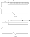
FIG. 1 is a schematic diagram of a structure of an electronic device according to an embodiment of this application; -
FIG. 2 is a schematic diagram of the electronic device inFIG. 1 after a stylus is taken out; -
FIG. 3 is a three-dimensional view of a stylus receiving apparatus according to an embodiment of this application; -
FIG. 4 is an expanded view of the stylus receiving apparatus inFIG. 3 ; -
FIG. 5 is a sectional view of the stylus receiving apparatus inFIG. 3 ; -
FIG. 6 is a diagram showing cooperation between the stylus receiving apparatus inFIG. 3 and a stylus; -
FIG. 7 is a top view ofFIG. 6 ; -
FIG. 8 is a sectional view taken along a line A-A inFIG. 7 ; -
FIG. 9 is an expanded view of an ejection mechanism in the stylus receiving apparatus shown inFIG. 4 ; -
FIG. 10 is a perspective view of a holding assembly in the stylus receiving apparatus shown inFIG. 4 ; -
FIG. 11 is an exploded view of the holding assembly inFIG. 10 ; and -
FIG. 12 is a diagram showing a control principle of a stylus receiving apparatus according to an embodiment of this application. - Reference numerals of main components:
Electronic device 10 Stylus 11 Device body 12 Stylus receiving apparatus 13 Bracket 14 Ejection mechanism 15 Holding assembly 16 Sensing assembly 17 Accommodating space 18 Exit/ Entrance port 19 Magnet part 20 Coil part 21 Seat frame 22 Cover 23 Connection lug 24 Sliding seat 25 Sliding member 26 Elastic member 27 Guide rod 28 Guide groove 29 Guide plate 30 Fastened end 31 Movable end 32 First locked position 33 Second locked position 34 Sleeve 35 Cooperating hole 36 Step surface 37 Positioning ring groove 38 Ring-shaped protrusion 39 Connection convex lug 40 Screw 41 Magnetic member 42 Hall element 43 Mounting groove 44 Lead 45 Inner hole 46 Inner circumferential surface 47 Outer circumferential surface 48 First axial end surface 49 Second axial end surface 50 First arc end surface 51 Second arc end surface 52 Power supply apparatus 53 Control switch 54 Control system 55 Held element 56 Guide groove 57 Guide convex bar 58 - The following clearly and completely describes technical solutions in embodiments of this application with reference to accompanying drawings in embodiments of this application. Apparently, the described embodiments are only some embodiments rather than all of embodiments of this application.
- It should be noted that when an element is referred to as being "fastened" to another element, it may be directly on another element, or a centered element may exist. When one element is considered to be "connected to" another element, it may be directly connected to another element, or a centered element may exist at the same time. When one element is considered to be "disposed" on another element, it may be directly disposed on another element, or a centered element may exist at the same time. The terms "vertical", "horizontal", "left", "right", and similar expressions are used herein for illustrative purposes only.
- Unless otherwise defined, all technical and scientific terms used in this specification have the same meaning as those commonly understood by a person skilled in the art of this application. The terms used in the specification of this application are merely intended to describe specific implementations, and are not intended to limit this application. The term "or/and" used in the specification includes any and all combinations of one or more associated listed items.
- Some implementations of this application are described in detail. If there is no conflict, the following implementations and the features in the implementations may be mutually combined.
- Referring to
FIG. 1 , this embodiment provides anelectronic device 10, including astylus 11 and adevice body 12. Thedevice body 12 includes astylus receiving apparatus 13, configured to receive thestylus 11. When thestylus 11 needs to be used, thestylus 11 may be taken out of thestylus receiving apparatus 13, as shown inFIG. 2 . - The
electronic device 10 in this embodiment may be a mobile phone, a laptop computer, a tablet computer, a laptop computer accessory, a tablet computer accessory, and a mobile phone accessory and another device that needs a stylus receiving function. - The
stylus receiving apparatus 13 may be disposed integrally in theelectronic device 10 as a part of thedevice body 12. Alternatively, the apparatus may be an independent product, and may be detachably attached, by using a connection structure, to thedevice body 12 that has no stylus receiving function for use. - Referring to
FIG. 3 to FIG. 8 together, this embodiment of this application provides astylus receiving apparatus 13, including abracket 14, anejection mechanism 15, a holdingassembly 16, and asensing assembly 17. Referring mainly toFIG. 8 , thebracket 14 defines anaccommodating space 18, and theaccommodating space 18 is provided with an exit/entrance port 19 for inserting thestylus 11. For the bar-shapedstylus 11, theaccommodating space 18 is approximately a bar-shaped groove hole structure in which the exit/entrance port 19 is disposed at an end, and a cross-section adapts thestylus 11, for example, is disposed as a square or a circle. Theejection mechanism 15 is disposed in theaccommodating space 18, and theejection mechanism 15 can be driven to a locked state or an unlocked state by thestylus 11 that is inserted into theaccommodating space 18. In the locked state, theejection mechanism 15 allows thestylus 11 to be received in theaccommodating space 18. In the unlocked state, theejection mechanism 15 is capable of ejecting thestylus 11 from the accommodating space 18 (a feasible implementation in which theejection mechanism 15 implements the locked state and the unlocked state is described below). The holdingassembly 16 is configured to cooperate with the held element 56 (such as a magnet) on thestylus 11, so as to hold thestylus 11. The holdingassembly 16 includes amagnet part 20 and acoil part 21. The holdingassembly 16 generates a first magnetic field when thecoil part 21 is powered off. The holdingassembly 16 generates a second magnetic field when thecoil part 21 is powered on. A holding force exerted by the second magnetic field on thestylus 11 is smaller than a holding force exerted by the first magnetic field on thestylus 11. Thesensing assembly 17 is communicatively connected to thecoil part 21. Thesensing assembly 17 senses a state change of theejection mechanism 15 by sensing movement of theejection mechanism 15. When thesensing assembly 17 senses that theejection mechanism 15 changes from an unlocked state to a locked state, thecoil part 21 is powered off. When thesensing assembly 17 senses that theejection mechanism 15 changes from the locked state to the unlocked state, thecoil part 21 is powered on. - A method for using the
stylus receiving apparatus 13 in this embodiment of this application is as follows: - when the
stylus 11 needs to be received, thestylus 11 is inserted from the exit/entrance port 19, so that thestylus 11 drives theejection mechanism 15 to change from the unlocked state to the locked state, and is received in theaccommodating space 18; and in this process, thesensing assembly 17 senses the state change, and controls thecoil part 21 to be in a power-off state, so that the first magnetic field of the holdingassembly 16 holds thestylus 11, so as to prevent thestylus 11 from falling out of theaccommodating space 18; and - when the
stylus 11 needs to be taken out, thestylus 11 is pressed, so that thestylus 11 drives theejection mechanism 15 to change from the locked state to the unlocked state; and in this process, thesensing assembly 17 senses the state change, and controls thecoil part 21 to be powered on, and a holding force exerted by the second magnetic field of the holdingassembly 16 on thestylus 11 is reduced, so that theejection mechanism 15 easily ejects thestylus 11 from the exit/entrance port 19 with a relatively small elastic force. - Therefore, it can be learned that the
stylus receiving apparatus 13 in this embodiment of this application has beneficial effects of reliably holding thestylus 11, pressing and taking out thestylus 11 with less force, better hand feeling, and better user experience. - Referring mainly to
FIG. 4 , in this implementation, thebracket 14 includes aseat frame 22 and acover 23, and thecover 23 is detachably connected to theseat frame 22, so as to enclose into theaccommodating space 18. When thecover 23 is detached from theseat frame 22, theaccommodating space 18 is opened. In this implementation, thedetachable seat frame 22 and thedetachable cover 23 are disposed, so as to facilitate operations such as disassembly/assembly and replacement of an internal structure (such as an ejection assembly) of thebracket 14. A connection manner between thecover 23 and theseat frame 22 may be clamping, or a connection is implemented by using a screw. In this embodiment, theseat frame 22 may be include aconnection lug 24, configured to implement a connection to another part of thedevice body 12. - The
ejection mechanism 15 in this embodiment of this application may be implemented in a plurality of forms. For example, referring toFIG. 9 together, in this implementation, theejection mechanism 15 includes a slidingseat 25, a slidingmember 26, anelastic member 27, and aguide rod 28. The slidingseat 25 is fixedly connected to thebracket 14, and is located in theaccommodating space 18. The slidingmember 26 may slidably cooperate with the slidingseat 25, and a sliding direction is along an axial direction of theaccommodating space 18; and the slidingmember 26 includes aguide plate 30 with aguide groove 29. Theelastic member 27 is elastically supported between the slidingseat 25 and the slidingmember 26, and can exert an elastic force on the slidingmember 26 in a direction toward the exit/entrance port 19. Theguide rod 28 includes a fastenedend 31 and amovable end 32. The fastenedend 31 and the slidingseat 25 are relatively fastened. Themovable end 32 can movably cooperate with theguide groove 29, and can move along theguide groove 29 when the slidingmember 26 is driven by thestylus 11 to move relative to the slidingseat 25. Theguide groove 29 includes a first lockedposition 33 and a second lockedposition 34 that are spaced along an axial direction of theaccommodating space 18, and theguide groove 29 can guide theguide rod 28 to move in a one-way cycle within theguide groove 29. A movement path passes through the first lockedposition 33 and the second lockedposition 34. For a specific implementation, refer to an arrangement manner of a common Push-Push mechanism. In the locked state, themovable end 32 is located in the first lockedposition 33, and theguide rod 28 pulls the slidingmember 26, so that the slidingmember 26 is limited to a position that is relatively far away from the exit/entrance port 19, and compresses theelastic member 27. In the unlocked state, themovable end 32 is located in the second lockedposition 34, and the slidingmember 26 is ejected by theelastic member 27 to a position closer to the exit/entrance port 19. This implementation provides anejection mechanism 15 that can be locked and unlocked by using the Push-Push mechanism. Theejection mechanism 15 can be easily locked to allow thestylus 11 to be received and held, and thestylus 11 is ejected by using theelastic member 27 of theejection mechanism 15. Optionally, the slidingmember 26 further includes asleeve 35, and thesleeve 35 is connected to an end of theguide plate 30 near the exit/entrance port 19, and is configured to adapt thestylus 11. For example, a cooperatinghole 36 is disposed on an end of thesleeve 35 facing thestylus 11, and an outer end of the cooperatinghole 36 is a cone adapted to the end of thestylus 11. In this implementation, thesleeve 35 is disposed to be connected to theguide plate 30, so that thestylus 11 easily transmits force to theguide plate 30 through thesleeve 35, so as to drive theguide plate 30 to move. Optionally, there is astep surface 37 between theguide plate 30 and thesleeve 35, theelastic member 27 is a helical spring, and theelastic member 27 is sleeved outside theguide plate 30, and an end of theelastic member 27 abuts against thestep surface 37. Optionally, theelastic member 27 abuts against thestep surface 37, and is disposed outside theguide plate 30. In this arrangement manner, theelastic member 27 overlaps with theguide plate 30 in a longitudinal direction, thereby reducing an overall length of theejection mechanism 15. - In this implementation, optionally, a
guide groove 57 parallel to an axial direction of thesleeve 35 is disposed on an outer circumference of thesleeve 35, and a guideconvex bar 58 corresponding to theguide groove 57 is disposed on an inner circumference of the slidingseat 25, so as to implement sliding cooperation between thesleeve 35 and the slidingseat 25 through between theguide groove 57 and the guideconvex bar 58, and limit relative rotation of thesleeve 35 and the slidingseat 25 in a circumferential direction. - In this implementation, optionally, the
accommodating space 18 of thebracket 14 includes apositioning ring groove 38 that is spaced along an axial direction, a corresponding ring-shapedprotrusion 39 is disposed on an outercircumferential surface 48 of the slidingseat 25, and the ring-shapedprotrusion 39 is adapted to the corresponding positioning groove. A connectionconvex lug 40 is further disposed on a side surface of the slidingseat 25, and the slidingseat 25 is connected to thebracket 14 by using the connectionconvex lug 40 that is fastened by ascrew 41. In this implementation, positioning and mounting of the slidingseat 25 can be easily implemented through cooperation between thepositioning ring groove 38 and the ring-shapedprotrusion 39 and connection of the connectionconvex lug 40. For thebracket 14 disposed as theseat frame 22 and thecover 23, grooves may be separately opened on theseat frame 22 and thecover 23, so that theseat frame 22 and thecover 23 are enclosed, in a combined state, into the foregoingpositioning ring groove 38. In another implementation, the slidingseat 25 may be disposed integrally on thebracket 14, so as to implement relatively fixed connection between the slidingseat 25 and thebracket 14. - Referring to
FIG. 4 andFIG. 5 together, in this embodiment, thesensing assembly 17 includes amagnetic member 42 and aHall element 43. Themagnetic member 42 is disposed in theejection mechanism 15, and can be displaced with a change of theejection mechanism 15 between a locked state and an unlocked state. TheHall element 43 and thebracket 14 are relatively fastened, and can sense displacement of themagnetic member 42. In this implementation, a state change of theejection mechanism 15 is determined based on movement that is of themagnetic element 42 with theejection mechanism 15 and that is sensed by theHall element 43, and thecoil part 21 is controlled to be powered on or powered off, so that thestylus 11 can be easily held firmly when being received, and a holding force when thestylus 11 is ejected can be easily reduced. In this implementation, optionally, a mountinggroove 44 is disposed on thesleeve 35, and themagnetic member 42 is disposed in the mountinggroove 44. TheHall element 43 and thebracket 14 are relatively fastened, and correspond to themagnetic member 42, so as to sense displacement of themagnetic member 42. In this implementation, the mountinggroove 44 is disposed on thesleeve 35 to accommodate themagnetic member 42, and a state change of theejection mechanism 15 is obtained based on movement of themagnetic member 42 with thesleeve 35 and sensing of theHall element 43. A structure is simple, and implementation is easy. TheHall element 43 may be disposed in theaccommodating space 18, and enters a main control system of theelectronic device 10 in a manner in which a lead 45 passes through thebracket 14 to outside of theaccommodating space 18. - Referring to
FIG. 10 ,FIG. 11 , andFIG. 4 together, there are a plurality of holdingassemblies 16 in this embodiment, and the plurality of holdingassemblies 16 are distributed along a circumferential direction, and are enclosed into a ring that communicates with theaccommodating space 18 in an axial direction. As shown in the figures, there are two holdingassemblies 16, and the twoholding assemblies 16 are approximately in a shape of a semicircular ring, so that the twoholding assemblies 16 can be enclosed into an approximately complete ring, and aninner hole 46 enclosed by the two holding assemblies may allow thestylus 11 to penetrate. In this implementation, a plurality of holdingassemblies 16 are enclosed into a ring, so that thestylus 11 can be held from each direction, thereby improving holding reliability. In addition, thecoil part 21 in each direction also generate a corresponding reverse magnetic field when the coil part is powered on, to offset at least a part of a holding force of themagnet part 20, so as to help eject thestylus 11. In other words, the heldelement 56 of thestylus 11 is disposed at any position in the circumferential direction of thestylus 11, and can be held by a part of the holdingassembly 16 on the side, so that thestylus 11 can be easily inserted and held at any angle. - Referring mainly to
FIG. 11 , in this implementation, themagnet part 20 is in a shape of an arc ring, that is, a structure of a ring that extends only in a circumferential direction, for example, a structure of a semicircular ring. Themagnet part 20 in a shape of an arc ring has an innercircumferential surface 47 and an outercircumferential surface 48 that are radially opposite, a firstaxial end surface 49 and a secondaxial end surface 50 that are axially opposite, and a firstarc end surface 51 and a secondarc end surface 52 that are archwise opposite. The firstaxial end surface 49, the firstarc end surface 51, the secondaxial end surface 50, and the secondarc end surface 52 are sequentially connected end-to-end to form a closed loop. Referring toFIG. 10 andFIG. 11 together, thecoil part 21 is formed by winding a wire around themagnet part 20 along the closed loop, and thecoil part 21 can be powered on to generate a magnetic field opposite to a magnetic field of themagnet part 20. As shown inFIG. 11 , themagnet part 20 may be made of a permanent magnet. Themagnet part 20 has a magnetic field along a radial direction, and the radially inner side is the N pole, the radially outer side is the S pole. Correspondingly, after thecoil part 21 is powered on in the current direction I shown in the figure, a magnetic field is generated in the radial direction inside the space enclosed by thecoil part 21, and the radially inner side is the S pole, the radially outer side is the N pole. In this way, when thecoil part 21 is not powered on, a first magnetic field generated by the holdingassembly 16 is mainly represented as a magnetic field generated by themagnet part 20; and when thestylus 11 is received in theaccommodating space 18, the N pole of the heldelement 56 of thestylus 11 corresponds to the holdingassembly 16, so that thestylus 11 is reliably held on the holdingassembly 16 and cannot easily fall out. After thecoil part 21 is powered on in the current direction I shown in the figure, a second magnetic field generated by the holdingassembly 16 is mainly represented as a magnetic field generated by themagnet part 20 and a superposed magnetic field generated by thecoil part 21; and the magnetic field generated by thecoil part 21 is mainly located on an inner side of thecoil part 21, namely, a region in which themagnet part 20 is located, and the magnetic field generated by thecoil part 21 is opposite to the magnetic field generated by themagnet part 20, so that the effects of the two magnetic fields are offset, thereby reducing the holding force for thestylus 11. Certainly, a magnitude of a magnetic field of thecoil part 21 may be controlled based on a magnitude of a powered-on current. Generally, a current can be controlled, so that a magnetic field generated by thecoil part 21 is equal to that of themagnet part 20, and the two are completely offset, and only the holding force needs to be reduced. - In this implementation, the wire used for winding into the
coil part 21 may be a copper wire or another metal wire. Thewound coil part 21 may further be cured outside themagnet part 20 by using insulation cement or another connection material, to improve integration degree of the two. In this implementation, the holdingassembly 16 that integrates themagnet part 20 and thecoil part 21 is formed by winding a wire around themagnet part 20 along the closed loop. In the holdingassembly 16 formed in this way, a magnetic field distribution when thecoil part 21 is powered on and a magnetic field distribution of themagnet part 20 are basically consistent with each other, and it is easy to control the overall magnetic field of the holdingassembly 16 through inverse superposition of magnetic fields of thecoil part 21 and themagnet part 20, so as to reliably control a holding force, without affecting a magnetic field impact range after superposition due to a relatively poor magnetic field range overlap between thecoil part 21 and themagnet part 20. Optionally, thecoil part 21 is defined between an innercircumferential surface 47 and an outercircumferential surface 48 of the arc ring. Specifically, during winding of the wire, the wire is not wound to the innercircumferential surface 47 and the outercircumferential surface 48 of the arc ring In this implementation, a winding range of thecoil part 21 is located between the innercircumferential surface 47 and the outercircumferential surface 48 of the arc ring, so that winding of thecoil part 21 does not increase a thickness (that is, spacing between the innercircumferential surface 47 and the outer circumferential surface 48) of themagnet part 20, thereby facilitating mounting of the holdingassembly 16 and reducing required mounting space. For example, when thebracket 14 is disposed in an embedded manner, the arrangement manner may be implemented only if thebracket 14 has a relatively small wall thickness, and no additional space is occupied. In addition, in the holdingassembly 16 of this structure, thecoil part 21 does not protrude from the outercircumferential surface 48 of themagnet part 20, and thecoil part 21 will not be easily disconnected or leak electricity due to an external force or impact. - For an implementation when there are two holding
assemblies 16, one of the twoholding assemblies 16 is connected to theseat frame 22, the other is connected to thecover 23, and when thecover 23 and theseat frame 22 are combined, the twoholding assemblies 16 are enclosed into a ring that communicates with theaccommodating space 18 in an axial direction, to allow thestylus 11 to penetrate. In this implementation, the twoholding assemblies 16 are separately mounted on theseat frame 22 and thecover 23, and are enclosed into a ring that communicates with theaccommodating space 18, to allow thestylus 11 to penetrate, and thestylus 11 is separately held from two sides. The holdingassembly 16 may be integrally embedded in a position corresponding to theseat frame 22/cover 23, or may be connected to theseat frame 22/cover 23 in a manner such as bonding or clamping. - In this embodiment, the held
element 56 of thestylus 11 may be disposed on an outer circumference of thestylus 11 or inside thestylus 11. - In this embodiment, the
stylus receiving apparatus 13 includes a power supply apparatus 53 (refer toFIG. 12 ), configured to supply power to thecoil part 21 and/or thesensing assembly 17. A power supply mode of thepower supply apparatus 53 is battery power supply or wireless power supply. In this implementation, thestylus receiving apparatus 13 is supplied power by additionally providing a battery for thestylus receiving apparatus 13 or by using a device power supply of theelectronic device 10 in a wired or wireless manner. - An embodiment of this application further provides a stylus receiving method. Based on the foregoing
stylus receiving apparatus 13, the stylus receiving method includes: - when a
stylus 11 needs to be received, inserting thestylus 11 from an exit/entrance port 19, so that thestylus 11 drives anejection mechanism 15 to change from an unlocked state to a locked state, and is received in anaccommodating space 18; in addition, controlling acoil part 21 to be in a power-off state, so that a first magnetic field of a holdingassembly 16 holds thestylus 11; and - when the
stylus 11 needs to be taken out, pressing thestylus 11, so that thestylus 11 drives theejection mechanism 15 to change from the locked state to the unlocked state; in addition, controlling thecoil part 21 to be powered on, so that the holdingassembly 16 generates a second magnetic field, and theejection mechanism 15 easily ejects thestylus 11 from the exit/entrance port 19. - The stylus receiving method in this embodiment of this application is based on the foregoing
stylus receiving apparatus 13, which can easily and effectively implement receiving and ejection of thestylus 11, ensure good hand feeling, and improve user experience. - In a possible implementation, a
control system 55 receives a state change of theejection mechanism 15 that is sensed by thesensing assembly 17, and controls, based on the corresponding state change, thecoil part 21 to be powered on or powered off. Thecontrol system 55 in this implementation may be a main control system of anelectronic device 10 in which thestylus receiving apparatus 13 is used. That is, the control of thestylus receiving apparatus 13 for receiving a signal of thesensing assembly 17 and controlling thecoil part 21 to be powered on/powered off is implemented by the main control system of theelectronic device 10. -
FIG. 12 is a control principle diagram of astylus receiving apparatus 13 according to an embodiment of this application. Referring toFIG. 12 , thepower supply apparatus 53 separately supplies power to theHall element 43 and thecoil part 21. In addition, acontrol switch 54 controls a branch that is used by thepower supply apparatus 53 to supply power to thecoil part 21 to be connected or disconnected, and thecontrol system 55 is communicatively connected to theHall element 43 and thecontrol switch 54. With reference to the foregoing description, when in use, and thestylus 11 is inserted to drive theejection mechanism 15 to change from the unlocked state to the locked state, theHall element 43 senses the state change, and transmits a signal to thecontrol system 55; and thecontrol system 55 controls thecontrol switch 54 to be turned off, so that thepower supply apparatus 53 stops supplying to thecoil part 21, and the holdingassembly 16 holds thestylus 11. When thestylus 11 is taken out, theejection mechanism 15 changes from the locked state to the unlocked state, and theelastic member 27 of theejection mechanism 15 ejects thestylus 11; in this case, theHall element 43 senses the state change, and transmits a signal to thecontrol system 55; and thecontrol system 55 controls thecontrol switch 54 to be turned on, so that thepower supply apparatus 53 supplies power to thecoil part 21, and a magnetic field generated by thecoil part 21 offsets at least a part of the magnetic field of themagnet part 20,the holding force exerted by the holdingassembly 16 on thestylus 11 is reduced, and theelastic member 27 only needs less elasticity to normally eject thestylus 11. - In another implementation, any other suitable method may be used for controlling the
coil part 21 to be powered on/powered off. - According to the foregoing description, the
stylus receiving apparatus 13, the stylus receiving method, and theelectronic device 10 in embodiments of this application have beneficial effects such as reliably holding thestylus 11, better hand feeling in receiving or taking out thestylus 11, and improved user experience. - The foregoing implementation are merely used to describe the technical solutions of this application, but are not limited thereto. Although this application is described in detail with reference to the foregoing preferred implementation, persons of ordinary skill in the art should understand that modification or equivalent replacement of the technical solutions of this application may be performed without departing from the spirit and scope of the technical solutions of this application.
Claims (17)
- A stylus receiving apparatus, comprising:a bracket, wherein the bracket defines an accommodating space, and the accommodating space has an exit/entrance port for inserting a stylus;an ejection mechanism, wherein the ejection mechanism is disposed in the accommodating space, and the ejection mechanism can be driven to a locked state or an unlocked state by the stylus that is inserted into the accommodating space; in the locked state, the ejection mechanism allows the stylus to be received in the accommodating space; and in the unlocked state, the ejection mechanism is capable of ejecting the stylus from the accommodating space;a holding assembly, configured to cooperate with a held element on the stylus, so as to hold the stylus; wherein the holding assembly comprises a magnet part and a coil part; the holding assembly generates a first magnetic field when the coil part is powered off; the holding assembly generates a second magnetic field when the coil part is powered on; and a holding force exerted by the second magnetic field on the stylus is smaller than a holding force exerted by the first magnetic field on the stylus; anda sensing assembly, wherein the sensing assembly is communicatively connected to the coil part; the sensing assembly senses a state change of the ejection mechanism by sensing movement of the ejection mechanism, and the coil part is powered off when the sensing assembly senses that the ejection mechanism changes from an unlocked state to a locked state; and the coil part is powered on when the sensing assembly senses that the ejection mechanism changes from the locked state to the unlocked state.
- The stylus receiving apparatus according to claim 1, whereinthe magnet part is in a shape of an arc ring, the arc ring has an inner circumferential surface and an outer circumferential surface that are radially opposite, a first axial end surface and a second axial end surface that are axially opposite, and a first arc end surface and a second arc end surface that are archwise opposite; and the first axial end surface, the first arc end surface, the second axial end surface, and the second arc end surface are sequentially connected end-to-end to form a closed loop; andthe coil part is formed by winding a wire around the magnet part along the closed loop, and the coil part can be powered on to generate a magnetic field opposite to a magnetic field of the magnet part.
- The stylus receiving apparatus according to claim 2, wherein
the coil part is defined between an inner circumferential surface and an outer circumferential surface of the arc ring. - The stylus receiving apparatus according to claim 1, wherein
there are a plurality of holding assemblies, and the plurality of holding assemblies are distributed along a circumferential direction, and are enclosed into a ring that communicates with the accommodating space in an axial direction, to allow the stylus to penetrate. - The stylus receiving apparatus according to claim 1, whereinthe sensing assembly comprises a magnetic member and a Hall element;the magnetic member is disposed in the ejection mechanism, and can be displaced with a change of the ejection mechanism between a locked state and an unlocked state; andthe Hall element and the bracket are relatively fastened, and can sense displacement of the magnetic member.
- The stylus receiving apparatus according to claim 1, whereinthe stylus receiving apparatus further comprises a power supply apparatus, configured to supply power to the coil part and/or the sensing assembly; anda power supply mode of the power supply apparatus is battery power supply or wireless power supply.
- The stylus receiving apparatus according to claim 1, wherein
the bracket comprises a seat frame and a cover, and the cover is detachably connected to the seat frame, to enclose into the accommodating space; and when the cover is detached from the seat frame, the accommodating space is opened. - The stylus receiving apparatus according to claim 7, wherein
there are two holding assemblies, and both are in a shape of a semicircular ring; and one of the two holding assemblies is connected to the seat frame, the other is connected to the cover, and when the cover and the seat frame are combined, the two holding assemblies are enclosed into a ring that communicates with the accommodating space in an axial direction, to allow the stylus to penetrate. - The stylus receiving apparatus according to claim 1, whereinthe ejection mechanism comprises a sliding seat, a sliding member, an elastic member, and a guide rod;the sliding seat is fixedly connected to the bracket, and is located in the accommodating space;the sliding member may slidably cooperate with the sliding seat, and a sliding direction is along an axial direction of the accommodating space; and the sliding member comprises a guide plate with a guide groove;the elastic member is elastically supported between the sliding seat and the sliding member, and can exert an elastic force on the sliding member in a direction toward the exit/entrance port;the guide rod comprises a fastened end and a movable end, the fastened end and the sliding seat are relatively fastened, and the movable end can movably cooperate with the guide groove, and can move along the guide groove when the sliding member is driven by the stylus to move relative to the sliding seat;the guide groove comprises a first locked position and a second locked position that are spaced along the axial direction of the accommodating space;in the locked state, the movable end is located in the first locked position, and the guide rod pulls the sliding member, so that the sliding member is limited to a position that is relatively far away from the exit/entrance port, and compresses the elastic member; andin the unlocked state, the movable end is located in the second locked position, and the sliding member is ejected by the elastic member to a position closer to the exit/entrance port.
- The stylus receiving apparatus according to claim 9, wherein
the sliding member further comprises a sleeve, and the sleeve is connected to an end of the guide plate near the exit/entrance port, and is configured to adapt the stylus. - The stylus receiving apparatus according to claim 10, wherein
there is a step surface between the guide plate and the sleeve, the elastic member is a helical spring, and the elastic member is sleeved outside the guide plate, and an end of the elastic member abuts against the step surface. - The stylus receiving apparatus according to claim 10, whereina mounting groove is disposed on the sleeve;the sensing assembly comprises a magnetic member and a Hall element, and the magnetic member is disposed in the mounting groove; andthe Hall element and the bracket are relatively fastened, and can sense displacement of the magnetic member.
- The stylus receiving apparatus according to claim 9, whereinthe accommodating space of the bracket has a positioning ring groove that is spaced along an axial direction, a corresponding ring-shaped protrusion is disposed on an outer circumferential surface of the sliding seat, and the ring-shaped protrusion is adapted to a corresponding positioning groove; anda connection convex lug is further disposed on a side surface of the sliding seat, and the sliding seat is fixedly connected to the bracket by using the connection convex lug.
- A stylus receiving method, wherein the method is based on the stylus receiving apparatus according to any one of claims 1 to 13, and the stylus receiving method comprises:when a stylus needs to be received, inserting the stylus from the exit/entrance port, so that the stylus drives an ejection mechanism to change from an unlocked state to a locked state, and is received in an accommodating space; in addition, controlling a coil part to be in a power-off state, so that a first magnetic field of a holding assembly holds the stylus; andwhen the stylus needs to be taken out, pressing the stylus, so that the stylus drives the ejection mechanism to change from the locked state to the unlocked state; in addition, controlling the coil part to be powered on, so that the holding assembly generates a second magnetic field, and the ejection mechanism easily ejects the stylus from the exit/entrance port.
- The stylus receiving method according to claim 14, wherein
a control system receives a state change of the ejection mechanism that is sensed by the sensing assembly, and controls, based on the corresponding state change, the coil part to be powered on or powered off. - An electronic device, comprising:a stylus, wherein a held element is disposed on the stylus; anda device body, wherein the device body comprises the stylus receiving apparatus according to any one of claims 1 to 13, and the holding assembly can hold the held element.
- The electronic device according to claim 16, wherein
the electronic device further comprises a device power supply, configured to supply power to the coil part and/or the sensing assembly in a wired or wireless manner.
Applications Claiming Priority (2)
| Application Number | Priority Date | Filing Date | Title |
|---|---|---|---|
| CN202111142047.8A CN114003138B (en) | 2021-09-28 | 2021-09-28 | Stylus pen accommodating device and method and electronic equipment |
| PCT/CN2022/113754 WO2023051087A1 (en) | 2021-09-28 | 2022-08-19 | Stylus storage apparatus and method, and electronic device |
Publications (3)
| Publication Number | Publication Date |
|---|---|
| EP4206874A1 true EP4206874A1 (en) | 2023-07-05 |
| EP4206874A4 EP4206874A4 (en) | 2024-04-10 |
| EP4206874B1 EP4206874B1 (en) | 2025-02-26 |
Family
ID=79921825
Family Applications (1)
| Application Number | Title | Priority Date | Filing Date |
|---|---|---|---|
| EP22871046.3A Active EP4206874B1 (en) | 2021-09-28 | 2022-08-19 | Stylus storage apparatus and method, and electronic device |
Country Status (4)
| Country | Link |
|---|---|
| US (1) | US12111685B2 (en) |
| EP (1) | EP4206874B1 (en) |
| CN (1) | CN114003138B (en) |
| WO (1) | WO2023051087A1 (en) |
Families Citing this family (3)
| Publication number | Priority date | Publication date | Assignee | Title |
|---|---|---|---|---|
| CN114003138B (en) * | 2021-09-28 | 2022-09-02 | 荣耀终端有限公司 | Stylus pen accommodating device and method and electronic equipment |
| CN114721469A (en) * | 2022-03-07 | 2022-07-08 | 维沃移动通信有限公司 | Electronic device and physiological parameter detection method |
| CN117687522B (en) * | 2022-04-06 | 2024-11-08 | 荣耀终端有限公司 | Accessory detection system |
Family Cites Families (21)
| Publication number | Priority date | Publication date | Assignee | Title |
|---|---|---|---|---|
| US6545577B2 (en) * | 2001-06-18 | 2003-04-08 | Hewlett-Packard Company | Frictionless pen ejector mechanism |
| CN201839561U (en) * | 2010-10-29 | 2011-05-18 | 汉王科技股份有限公司 | Stylus pen inserting and drawing mechanism and electronic device using same |
| CN201938001U (en) | 2010-11-26 | 2011-08-17 | 英业达股份有限公司 | Portable electronic device and stylus used therefor |
| JP5100864B1 (en) * | 2011-06-30 | 2012-12-19 | 株式会社東芝 | Electronics |
| US8964379B2 (en) * | 2012-08-20 | 2015-02-24 | Microsoft Corporation | Switchable magnetic lock |
| KR20150062691A (en) * | 2013-11-29 | 2015-06-08 | 삼성전자주식회사 | Electronic device having ejectable touch pen automatically |
| KR20160046668A (en) * | 2014-10-21 | 2016-04-29 | 삼성전자주식회사 | Method for executing a function and an electronic device implementing the same |
| KR20170019995A (en) * | 2015-08-13 | 2017-02-22 | 삼성전자주식회사 | Apparatus and method for operating a detachable electronic device and an electronic device |
| US10153077B2 (en) * | 2016-08-19 | 2018-12-11 | Microsoft Technology Licensing, Llc | Input device attachment/detachment mechanism for computing devices |
| US11402873B2 (en) * | 2018-12-19 | 2022-08-02 | Apple Inc. | Release mechanisms for coupled devices |
| KR102681717B1 (en) * | 2018-12-28 | 2024-07-05 | 삼성전자주식회사 | Electronic device for performing communication with pen input device having a pluarlity of input buttons and method for controlling thereof |
| CN110825170B (en) * | 2019-11-07 | 2021-05-11 | 广东虹勤通讯技术有限公司 | Device for cooperating with stylus insertion and equipment with stylus insertion function |
| CN112099651A (en) * | 2020-08-18 | 2020-12-18 | 深圳传音控股股份有限公司 | Handwriting pen, electronic terminal and handwriting pen system |
| KR20220051725A (en) * | 2020-10-19 | 2022-04-26 | 삼성전자주식회사 | Electronic device for controlling operation of electronic pen device, operation method in the electronic device and non-transitory storage medium |
| CN112558790B (en) * | 2020-12-15 | 2024-12-13 | 维沃移动通信有限公司 | Touch pen, control method and device of electronic device, and electronic device |
| CN214202219U (en) * | 2020-12-31 | 2021-09-14 | 联想(北京)有限公司 | Ejection device and electronic equipment |
| CN112987858B (en) * | 2021-04-15 | 2024-01-30 | 维沃移动通信有限公司 | Electronic equipment |
| US11630489B2 (en) * | 2021-08-25 | 2023-04-18 | Microsoft Technology Licensing, Llc | Computing device with stylus retention |
| TWI769087B (en) * | 2021-09-24 | 2022-06-21 | 宏碁股份有限公司 | Pick-and-place mechanism for stylus |
| CN114003138B (en) | 2021-09-28 | 2022-09-02 | 荣耀终端有限公司 | Stylus pen accommodating device and method and electronic equipment |
| US11687118B2 (en) * | 2021-11-11 | 2023-06-27 | Getac Technology Corporation | Casing assembly |
-
2021
- 2021-09-28 CN CN202111142047.8A patent/CN114003138B/en active Active
-
2022
- 2022-08-19 WO PCT/CN2022/113754 patent/WO2023051087A1/en not_active Ceased
- 2022-08-19 EP EP22871046.3A patent/EP4206874B1/en active Active
- 2022-08-19 US US18/248,708 patent/US12111685B2/en active Active
Also Published As
| Publication number | Publication date |
|---|---|
| US20230393615A1 (en) | 2023-12-07 |
| US12111685B2 (en) | 2024-10-08 |
| CN114003138B (en) | 2022-09-02 |
| EP4206874B1 (en) | 2025-02-26 |
| CN114003138A (en) | 2022-02-01 |
| WO2023051087A1 (en) | 2023-04-06 |
| EP4206874A4 (en) | 2024-04-10 |
Similar Documents
| Publication | Publication Date | Title |
|---|---|---|
| US20230393615A1 (en) | Stylus receiving apparatus, method, and electronic device | |
| US8553419B2 (en) | Card tray ejection mechanism and electronic device using the same | |
| US20080300615A1 (en) | Wireless tattoo applicator | |
| US20130293731A1 (en) | Remote controller device for self-photography using a mobile phone camera | |
| CN113099083A (en) | Camera assembly, mobile terminal and control method of camera assembly | |
| CN109729446B (en) | Earphone charging box | |
| EP4140355B1 (en) | Earphone case and wireless earphone | |
| CN113206933A (en) | Camera assembly, mobile terminal and control method of camera assembly | |
| US11614775B2 (en) | Accommodating cylinder, touch pen assembly, and protective case | |
| KR100589077B1 (en) | Medical injector | |
| US20210396045A1 (en) | Low-power-consumption intelligent electric lock mechanism | |
| US20160302560A1 (en) | Voice coil motor and brush unit comprising it | |
| EP4742518A1 (en) | Self-resetting magnetic suspension power generator, and power generation method, resetting method and use thereof | |
| EP4393343B1 (en) | Locking structure used to combine with fabric | |
| CN212940998U (en) | Massage device | |
| WO2018068348A1 (en) | Locking device | |
| CN219982604U (en) | Cosmetic mirror assembly and mirror cabinet | |
| CN211549214U (en) | Vehicle lock with Bluetooth | |
| CN107809870B (en) | Closing mechanism of remote controller battery cover | |
| CN216356029U (en) | Magnetic attraction wireless charger with telescopic storage wire | |
| CN115549713B (en) | Electronic devices | |
| CN219437131U (en) | Earphone and earphone bin | |
| CN116211112B (en) | Makeup mirror components and mirror cabinets | |
| CN215779791U (en) | Fascia gun | |
| CN220608177U (en) | Detachable pot handle and pot |
Legal Events
| Date | Code | Title | Description |
|---|---|---|---|
| STAA | Information on the status of an ep patent application or granted ep patent |
Free format text: STATUS: UNKNOWN |
|
| STAA | Information on the status of an ep patent application or granted ep patent |
Free format text: STATUS: THE INTERNATIONAL PUBLICATION HAS BEEN MADE |
|
| PUAI | Public reference made under article 153(3) epc to a published international application that has entered the european phase |
Free format text: ORIGINAL CODE: 0009012 |
|
| STAA | Information on the status of an ep patent application or granted ep patent |
Free format text: STATUS: REQUEST FOR EXAMINATION WAS MADE |
|
| 17P | Request for examination filed |
Effective date: 20230328 |
|
| AK | Designated contracting states |
Kind code of ref document: A1 Designated state(s): AL AT BE BG CH CY CZ DE DK EE ES FI FR GB GR HR HU IE IS IT LI LT LU LV MC MK MT NL NO PL PT RO RS SE SI SK SM TR |
|
| A4 | Supplementary search report drawn up and despatched |
Effective date: 20240312 |
|
| RIC1 | Information provided on ipc code assigned before grant |
Ipc: H04M 1/21 20060101ALI20240305BHEP Ipc: G06F 1/16 20060101ALI20240305BHEP Ipc: G06F 3/0354 20130101AFI20240305BHEP |
|
| GRAP | Despatch of communication of intention to grant a patent |
Free format text: ORIGINAL CODE: EPIDOSNIGR1 |
|
| STAA | Information on the status of an ep patent application or granted ep patent |
Free format text: STATUS: GRANT OF PATENT IS INTENDED |
|
| DAV | Request for validation of the european patent (deleted) | ||
| DAX | Request for extension of the european patent (deleted) | ||
| INTG | Intention to grant announced |
Effective date: 20241002 |
|
| GRAS | Grant fee paid |
Free format text: ORIGINAL CODE: EPIDOSNIGR3 |
|
| GRAA | (expected) grant |
Free format text: ORIGINAL CODE: 0009210 |
|
| STAA | Information on the status of an ep patent application or granted ep patent |
Free format text: STATUS: THE PATENT HAS BEEN GRANTED |
|
| AK | Designated contracting states |
Kind code of ref document: B1 Designated state(s): AL AT BE BG CH CY CZ DE DK EE ES FI FR GB GR HR HU IE IS IT LI LT LU LV MC MK MT NL NO PL PT RO RS SE SI SK SM TR |
|
| REG | Reference to a national code |
Ref country code: GB Ref legal event code: FG4D |
|
| REG | Reference to a national code |
Ref country code: CH Ref legal event code: EP |
|
| REG | Reference to a national code |
Ref country code: DE Ref legal event code: R096 Ref document number: 602022011256 Country of ref document: DE |
|
| REG | Reference to a national code |
Ref country code: IE Ref legal event code: FG4D |
|
| REG | Reference to a national code |
Ref country code: NL Ref legal event code: FP |
|
| PG25 | Lapsed in a contracting state [announced via postgrant information from national office to epo] |
Ref country code: RS Free format text: LAPSE BECAUSE OF FAILURE TO SUBMIT A TRANSLATION OF THE DESCRIPTION OR TO PAY THE FEE WITHIN THE PRESCRIBED TIME-LIMIT Effective date: 20250526 |
|
| PG25 | Lapsed in a contracting state [announced via postgrant information from national office to epo] |
Ref country code: FI Free format text: LAPSE BECAUSE OF FAILURE TO SUBMIT A TRANSLATION OF THE DESCRIPTION OR TO PAY THE FEE WITHIN THE PRESCRIBED TIME-LIMIT Effective date: 20250226 |
|
| PG25 | Lapsed in a contracting state [announced via postgrant information from national office to epo] |
Ref country code: PL Free format text: LAPSE BECAUSE OF FAILURE TO SUBMIT A TRANSLATION OF THE DESCRIPTION OR TO PAY THE FEE WITHIN THE PRESCRIBED TIME-LIMIT Effective date: 20250226 |
|
| PG25 | Lapsed in a contracting state [announced via postgrant information from national office to epo] |
Ref country code: ES Free format text: LAPSE BECAUSE OF FAILURE TO SUBMIT A TRANSLATION OF THE DESCRIPTION OR TO PAY THE FEE WITHIN THE PRESCRIBED TIME-LIMIT Effective date: 20250226 |
|
| REG | Reference to a national code |
Ref country code: LT Ref legal event code: MG9D |
|
| PG25 | Lapsed in a contracting state [announced via postgrant information from national office to epo] |
Ref country code: NO Free format text: LAPSE BECAUSE OF FAILURE TO SUBMIT A TRANSLATION OF THE DESCRIPTION OR TO PAY THE FEE WITHIN THE PRESCRIBED TIME-LIMIT Effective date: 20250526 Ref country code: IS Free format text: LAPSE BECAUSE OF FAILURE TO SUBMIT A TRANSLATION OF THE DESCRIPTION OR TO PAY THE FEE WITHIN THE PRESCRIBED TIME-LIMIT Effective date: 20250626 |
|
| PG25 | Lapsed in a contracting state [announced via postgrant information from national office to epo] |
Ref country code: HR Free format text: LAPSE BECAUSE OF FAILURE TO SUBMIT A TRANSLATION OF THE DESCRIPTION OR TO PAY THE FEE WITHIN THE PRESCRIBED TIME-LIMIT Effective date: 20250226 |
|
| PG25 | Lapsed in a contracting state [announced via postgrant information from national office to epo] |
Ref country code: PT Free format text: LAPSE BECAUSE OF FAILURE TO SUBMIT A TRANSLATION OF THE DESCRIPTION OR TO PAY THE FEE WITHIN THE PRESCRIBED TIME-LIMIT Effective date: 20250626 Ref country code: LV Free format text: LAPSE BECAUSE OF FAILURE TO SUBMIT A TRANSLATION OF THE DESCRIPTION OR TO PAY THE FEE WITHIN THE PRESCRIBED TIME-LIMIT Effective date: 20250226 |
|
| PG25 | Lapsed in a contracting state [announced via postgrant information from national office to epo] |
Ref country code: GR Free format text: LAPSE BECAUSE OF FAILURE TO SUBMIT A TRANSLATION OF THE DESCRIPTION OR TO PAY THE FEE WITHIN THE PRESCRIBED TIME-LIMIT Effective date: 20250527 Ref country code: BG Free format text: LAPSE BECAUSE OF FAILURE TO SUBMIT A TRANSLATION OF THE DESCRIPTION OR TO PAY THE FEE WITHIN THE PRESCRIBED TIME-LIMIT Effective date: 20250226 |
|
| REG | Reference to a national code |
Ref country code: AT Ref legal event code: MK05 Ref document number: 1771270 Country of ref document: AT Kind code of ref document: T Effective date: 20250226 |
|
| PGFP | Annual fee paid to national office [announced via postgrant information from national office to epo] |
Ref country code: NL Payment date: 20250704 Year of fee payment: 4 |
|
| PG25 | Lapsed in a contracting state [announced via postgrant information from national office to epo] |
Ref country code: SE Free format text: LAPSE BECAUSE OF FAILURE TO SUBMIT A TRANSLATION OF THE DESCRIPTION OR TO PAY THE FEE WITHIN THE PRESCRIBED TIME-LIMIT Effective date: 20250226 |
|
| PG25 | Lapsed in a contracting state [announced via postgrant information from national office to epo] |
Ref country code: SM Free format text: LAPSE BECAUSE OF FAILURE TO SUBMIT A TRANSLATION OF THE DESCRIPTION OR TO PAY THE FEE WITHIN THE PRESCRIBED TIME-LIMIT Effective date: 20250226 |
|
| PG25 | Lapsed in a contracting state [announced via postgrant information from national office to epo] |
Ref country code: DK Free format text: LAPSE BECAUSE OF FAILURE TO SUBMIT A TRANSLATION OF THE DESCRIPTION OR TO PAY THE FEE WITHIN THE PRESCRIBED TIME-LIMIT Effective date: 20250226 |
|
| PGFP | Annual fee paid to national office [announced via postgrant information from national office to epo] |
Ref country code: DE Payment date: 20250702 Year of fee payment: 4 |
|
| PG25 | Lapsed in a contracting state [announced via postgrant information from national office to epo] |
Ref country code: IT Free format text: LAPSE BECAUSE OF FAILURE TO SUBMIT A TRANSLATION OF THE DESCRIPTION OR TO PAY THE FEE WITHIN THE PRESCRIBED TIME-LIMIT Effective date: 20250226 |
|
| PG25 | Lapsed in a contracting state [announced via postgrant information from national office to epo] |
Ref country code: AT Free format text: LAPSE BECAUSE OF FAILURE TO SUBMIT A TRANSLATION OF THE DESCRIPTION OR TO PAY THE FEE WITHIN THE PRESCRIBED TIME-LIMIT Effective date: 20250226 |
|
| PG25 | Lapsed in a contracting state [announced via postgrant information from national office to epo] |
Ref country code: EE Free format text: LAPSE BECAUSE OF FAILURE TO SUBMIT A TRANSLATION OF THE DESCRIPTION OR TO PAY THE FEE WITHIN THE PRESCRIBED TIME-LIMIT Effective date: 20250226 Ref country code: CZ Free format text: LAPSE BECAUSE OF FAILURE TO SUBMIT A TRANSLATION OF THE DESCRIPTION OR TO PAY THE FEE WITHIN THE PRESCRIBED TIME-LIMIT Effective date: 20250226 |
|
| PG25 | Lapsed in a contracting state [announced via postgrant information from national office to epo] |
Ref country code: RO Free format text: LAPSE BECAUSE OF FAILURE TO SUBMIT A TRANSLATION OF THE DESCRIPTION OR TO PAY THE FEE WITHIN THE PRESCRIBED TIME-LIMIT Effective date: 20250226 |
|
| PG25 | Lapsed in a contracting state [announced via postgrant information from national office to epo] |
Ref country code: SK Free format text: LAPSE BECAUSE OF FAILURE TO SUBMIT A TRANSLATION OF THE DESCRIPTION OR TO PAY THE FEE WITHIN THE PRESCRIBED TIME-LIMIT Effective date: 20250226 |
|
| REG | Reference to a national code |
Ref country code: DE Ref legal event code: R097 Ref document number: 602022011256 Country of ref document: DE |
|
| PLBE | No opposition filed within time limit |
Free format text: ORIGINAL CODE: 0009261 |
|
| STAA | Information on the status of an ep patent application or granted ep patent |
Free format text: STATUS: NO OPPOSITION FILED WITHIN TIME LIMIT |
|
| REG | Reference to a national code |
Ref country code: CH Ref legal event code: L10 Free format text: ST27 STATUS EVENT CODE: U-0-0-L10-L00 (AS PROVIDED BY THE NATIONAL OFFICE) Effective date: 20260107 |
|
| 26N | No opposition filed |
Effective date: 20251127 |
|
| REG | Reference to a national code |
Ref country code: CH Ref legal event code: H13 Free format text: ST27 STATUS EVENT CODE: U-0-0-H10-H13 (AS PROVIDED BY THE NATIONAL OFFICE) Effective date: 20260324 |
|
| PG25 | Lapsed in a contracting state [announced via postgrant information from national office to epo] |
Ref country code: MC Free format text: LAPSE BECAUSE OF FAILURE TO SUBMIT A TRANSLATION OF THE DESCRIPTION OR TO PAY THE FEE WITHIN THE PRESCRIBED TIME-LIMIT Effective date: 20250226 |
|
| PG25 | Lapsed in a contracting state [announced via postgrant information from national office to epo] |
Ref country code: LU Free format text: LAPSE BECAUSE OF NON-PAYMENT OF DUE FEES Effective date: 20250819 |
|
| PG25 | Lapsed in a contracting state [announced via postgrant information from national office to epo] |
Ref country code: CH Free format text: LAPSE BECAUSE OF NON-PAYMENT OF DUE FEES Effective date: 20250831 |