EP4206825A1 - Barillet pour pièce d'horlogerie - Google Patents
Barillet pour pièce d'horlogerie Download PDFInfo
- Publication number
- EP4206825A1 EP4206825A1 EP21218134.1A EP21218134A EP4206825A1 EP 4206825 A1 EP4206825 A1 EP 4206825A1 EP 21218134 A EP21218134 A EP 21218134A EP 4206825 A1 EP4206825 A1 EP 4206825A1
- Authority
- EP
- European Patent Office
- Prior art keywords
- barrel
- side wall
- outer turn
- friction surfaces
- mainspring
- Prior art date
- Legal status (The legal status is an assumption and is not a legal conclusion. Google has not performed a legal analysis and makes no representation as to the accuracy of the status listed.)
- Granted
Links
Images

Classifications
-
- G—PHYSICS
- G04—HOROLOGY
- G04B—MECHANICALLY-DRIVEN CLOCKS OR WATCHES; MECHANICAL PARTS OF CLOCKS OR WATCHES IN GENERAL; TIME PIECES USING THE POSITION OF THE SUN, MOON OR STARS
- G04B5/00—Automatic winding up
- G04B5/24—Protecting means preventing overwinding
-
- G—PHYSICS
- G04—HOROLOGY
- G04B—MECHANICALLY-DRIVEN CLOCKS OR WATCHES; MECHANICAL PARTS OF CLOCKS OR WATCHES IN GENERAL; TIME PIECES USING THE POSITION OF THE SUN, MOON OR STARS
- G04B1/00—Driving mechanisms
- G04B1/10—Driving mechanisms with mainspring
- G04B1/14—Mainsprings; Bridles therefor
- G04B1/145—Composition and manufacture of the springs
-
- G—PHYSICS
- G04—HOROLOGY
- G04B—MECHANICALLY-DRIVEN CLOCKS OR WATCHES; MECHANICAL PARTS OF CLOCKS OR WATCHES IN GENERAL; TIME PIECES USING THE POSITION OF THE SUN, MOON OR STARS
- G04B1/00—Driving mechanisms
- G04B1/10—Driving mechanisms with mainspring
- G04B1/16—Barrels; Arbors; Barrel axles
-
- G—PHYSICS
- G04—HOROLOGY
- G04B—MECHANICALLY-DRIVEN CLOCKS OR WATCHES; MECHANICAL PARTS OF CLOCKS OR WATCHES IN GENERAL; TIME PIECES USING THE POSITION OF THE SUN, MOON OR STARS
- G04B5/00—Automatic winding up
- G04B5/02—Automatic winding up by self-winding caused by the movement of the watch
Definitions
- the present invention relates to the field of watchmaking. It relates more specifically to a barrel intended to equip a timepiece with automatic winding. It also relates to a timepiece equipped with such a barrel.
- Barrels for self-winding timepieces conventionally comprise a drum in which is housed a mainspring wound in a spiral around a barrel arbor.
- the mainspring is not fixed to the side wall of the drum, but friction-coupled, via its last turn , using an elastic blade called a sliding flange.
- the friction coupling between the mainspring and the side wall of the drum must be calculated so that beyond a determined maximum driving torque, the last turn slides along said wall and thus reduces the tension of the mainspring.
- the surface condition of the inner side wall of the drum as well as its lubrication are factors strongly influencing the operation of this friction clutch. Another determining factor is the geometry of the inner side wall.
- the inner side wall of the drum has friction surfaces against which the end of the mainspring rubs, which wears the wall of the drum.
- a lubricant such as grease is deposited on the inner side wall of the drum.
- An object of the present invention is therefore to provide a cylinder to remedy this problem of wear.
- the invention solves the aforementioned drawbacks by proposing a barrel comprising a mainspring, the outer coil of which comprises a configuration providing two friction surfaces arranged in the upper and lower part of the outer coil, the friction surfaces being arranged to be in contact with the inner side wall of the barrel drum.
- the present invention relates to a barrel for a self-winding timepiece comprising a drum with axis AA provided with an inner side wall and a mainspring forming a winding comprising an outer turn whose end is coupled to friction with said inner side wall and free to slide against the inner side wall in the event of over-tensioning of the mainspring.
- the end of said outer turn comprises an outer face having two friction surfaces arranged in the upper and lower part of the outer turn and arranged to be in contact with the inner side wall so that the part between the surfaces of friction, called central part, is not in contact with the inner side wall, said central part forming a reservoir for a lubricant between the two friction surfaces and allowing the lubricant to be channeled to the center of the outer turn.
- the invention also relates to a watch movement comprising a barrel in accordance with the invention.
- the invention also relates to a watch comprising a movement equipped with a barrel according to the invention.
- the barrel 1 for a self-winding timepiece movement comprises a bottom 10 secured to a drum 11 with axis AA.
- a mainspring 2, also illustrated in figure 1 is wound inside the barrel 1, the inner coil 20 of the mainspring 2 being coupled to a plug 4 arranged around a shaft 5, and the outer coil 20 of the spring 2 being in contact with the inner side wall 12 drum 11.
- the spring 2 can be made in one piece and is in the form of a ribbon.
- the spring can thus be mounted on the bung 4 around the shaft 5 of the barrel.
- the outer coil 21 has an end 22 frictionally coupled with the inner side wall 12 and free to slide against the inner side wall 12 in the event of an overtension of the mainspring 2.
- the motor member 100 has a barrel 1 which comprises a cylindrical drum 11 in which the spring 2 is housed, a barrel shaft 5 and a bung 4 on which is fixed the inner turn 20 of the spring 2, and a cover 6 which close the drum 11.
- the drum 4 also comprises external toothing 13 which meshes with a pinion of a timer train (not shown).
- the end 22 of the outer turn 21 comprises an outer face 23 having two friction surfaces 24, 25 arranged in the upper and lower part of the outer turn 21 and arranged to be in contact with the inner side wall 12 so that the part between the friction surfaces 24, 25, called the central part 26, is not in contact with the inner side wall 12.
- the central part 26 forms a reservoir for a lubricant, the reservoir then being at least partly between the two friction surfaces 24, 25.
- the friction surfaces 24 and 25 are formed by removing material, over part of the thickness of the outer coil 21 or over the entire thickness, at the level of the middle part 26. This removal of material allows only the friction surfaces 24 and 25 to be in contact with the inner side wall 12 of the drum, the lubricant being brought back to the center thanks to the removal of material when the outer turn 21 slides against the drum.
- the friction surfaces 24, 25 are in the form of extra thicknesses located on the upper and lower part of the outer turn 21, the extra thicknesses thus being the only ones to be in contact with the inner side wall 12 of the drum and forming a reservoir for a lubricant at the middle part of the outer turn 21.
- the friction surfaces 24, 25 extend along the length of the outer turn 21, the length obviously being able to vary according to the needs of those skilled in the art. It is also obvious that the friction surfaces 24, 25 do not extend over the entire length of the outer turn 21 so as not to weaken it or make it too rigid, which would also be detrimental to the proper functioning of the barrel.
- the thickness of the removal of material varies increasingly from the end of the outer turn 21 and along the length of the outer turn.
- the removal of material takes the form of a funnel, a neck, a parabola or a semi-circle for example, so as to form a reservoir for the lubricant and guide it towards the center of the inner side wall of the drum.
- the end 22 of the outer turn 21 is deformed at its outer face 23 so as to form the two friction surfaces 24, 25.
- deformation of the outer turn 21 is obtained, for example, by stamping.
- the invention also relates to a timepiece movement as well as a timepiece equipped with a barrel according to the invention.
- a barrel is available which makes it possible to reduce the wear caused by the friction of the spring on the barrel drum.
Landscapes
- Physics & Mathematics (AREA)
- General Physics & Mathematics (AREA)
- Engineering & Computer Science (AREA)
- Metallurgy (AREA)
- Springs (AREA)
- Gears, Cams (AREA)
Abstract
Description
- La présente invention se rapporte au domaine de l'horlogerie. Elle concerne plus précisément un barillet destiné à équiper une pièce d'horlogerie à remontage automatique. Elle concerne également une pièce d'horlogerie équipée d'un tel barillet.
- Des barillets pour pièces d'horlogerie à remontage automatique comportent classiquement un tambour dans lequel est logé un ressort moteur enroulé en spirale autour d'un arbre de barillet. Pour éviter toute surtension du ressort moteur, pouvant le faire céder ou endommager le rouage du dispositif de remontage automatique, le ressort moteur n'est pas fixé à la paroi latérale du tambour, mais accouplé à friction, par l'intermédiaire de sa dernière spire, à l'aide d'une lame élastique appelée bride glissante. L'accouplement à friction entre le ressort moteur et la paroi latérale du tambour doit être calculé pour qu'au-delà d'un couple moteur maximum déterminé, la dernière spire glisse le long de ladite paroi et diminue ainsi la tension du ressort moteur. L'état de surface de la paroi latérale intérieure du tambour ainsi que sa lubrification sont des facteurs influençant fortement le fonctionnement de cet accouplement à friction. Un autre facteur déterminant concerne la géométrie de la paroi latérale intérieure.
- Selon l'état de la technique, la paroi latérale intérieure du tambour comporte des surfaces de frottement contre lesquelles l'extrémité du ressort moteur vient frotter, ce qui use la paroi du tambour. Pour remédier à ce problème, un lubrifiant tel que de la graisse est déposé sur la paroi latérale intérieure du tambour.
- Toutefois, le problème de l'usure est toujours présent, il s'amplifie au cours du temps et peut conduire à des dégâts importants, des dysfonctionnements ou même la rupture d'une pièce. En effet, le frottement de l'extrémité de la dernière spire du ressort moteur tend à racler et repousser la graisse sur les bords supérieur et inférieur du tambour. Pour finir, l'extrémité de la spire externe du ressort arrache des fines particules à la paroi du tambour, et celles-ci rendent le frottement encore plus abrasif, ce qui produit encore plus de particules et accélère le phénomène d'usure. A la longue, l'accouplement à friction entre le ressort moteur et la paroi latérale du barillet peut être sérieusement affecté.
- Ainsi, un démontage du barillet et un apport de graisse reste nécessaire pour maintenir des conditions de fonctionnement satisfaisantes.
- Un but de la présente invention est par conséquent de proposer un barillet permettant de remédier à ce problème d'usure.
- L'invention résout les inconvénients précités en proposant un barillet comprenant un ressort moteur dont la spire externe comprend une configuration ménageant deux surfaces de frottement disposées en partie haute et basse de la spire extérieure, les surfaces de frottement étant agencées pour être en contact avec la paroi latérale intérieure du tambour de barillet.
- A cet effet, la présente invention concerne un barillet pour pièce d'horlogerie à remontage automatique comprenant un tambour d'axe AA muni d'une paroi latérale intérieure et un ressort moteur formant un enroulement comportant une spire extérieure dont l'extrémité est accouplée à friction avec ladite paroi latérale intérieure et libre de glisser contre la paroi latérale intérieure en cas de surtension du ressort moteur.
- Selon l'invention, l'extrémité de ladite spire extérieure comprend une face externe présentant deux surfaces de frottement disposées en partie haute et basse de la spire extérieure et agencée pour être en contact avec la paroi latérale intérieure de manière que la partie entre les surfaces de frottement, dite partie centrale, ne soit pas en contact avec la paroi latérale intérieure, ladite partie centrale formant un réservoir pour un lubrifiant entre les deux surfaces de frottement et permettant de canaliser le lubrifiant au centre de la spire extérieure.
- Conformément à d'autres variantes avantageuses de l'invention :
- les surfaces de frottement se présentent sous la forme de surépaisseurs localisées en partie haute et basse de la spire extérieure ;
- les surfaces de frottement sont formées par un enlèvement de matière, sur une partie de l'épaisseur de la spire extérieure ou sur la totalité de l'épaisseur, au niveau de la partie médiane de la spire extérieure ;
- les surfaces de frottement s'étendent selon la longueur de la spire extérieure ;
- l'épaisseur de l'enlèvement de matière varie de manière croissante depuis l'extrémité de la spire externe et selon la longueur de la spire externe ;
- l'enlèvement de matière se présente sous la forme d'un entonnoir, d'un goulot, d'une parabole ou d'un demi-cercle ou toute autre géométrie apte à canaliser la graisse au centre de la piste de frottement de la lame contre le tambour.
- L'invention concerne également un mouvement horloger comprenant un barillet conforme à l'invention.
- L'invention concerne aussi une montre comprenant un mouvement équipé d'un barillet selon l'invention.
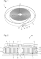
- Un barillet conforme à l'invention va maintenant être décrit dans ce qui suit faisant référence conjointement aux
figures 1, 2 et3a à 3d . - Tel qu'illustré à la
figure 2 , le barillet 1 pour mouvement d'horlogerie à remontage automatique comprend un fond 10 solidaire d'un tambour 11 d'axe AA. Un ressort moteur 2, aussi illustré à lafigure 1 , est enroulé à l'intérieur du barillet 1, la spire intérieure 20 du ressort moteur 2 étant couplée à une bonde 4 disposée autour d'un arbre 5, et la spire extérieure 20 du ressort 2 étant en contact avec la paroi latérale intérieure 12 du tambour 11. - Le ressort 2 peut être réalisé de manière monobloc et se présente sous la forme d'un ruban. Le ressort peut ainsi être monté sur la bonde 4 autour de l'arbre 5 du barillet.
- La spire extérieure 21 présente une extrémité 22 accouplée à friction avec la paroi latérale intérieure 12 et libre de glisser contre la paroi latérale intérieure 12 en cas de surtension du ressort moteur 2.
- Comme on peut l'observer à la
figure 2 , l'organe moteur 100 présente un barillet 1 qui comporte un tambour 11 cylindrique dans lequel est logé le ressort 2, un arbre de barillet 5 et un bonde 4 sur laquelle est fixée la spire intérieure 20 du ressort 2, et un couvercle 6 qui ferme le tambour 11. - Le tambour 4 comporte également une denture externe 13 qui engrène avec un pignon d'un rouage de minuterie (non représenté).
- Selon l'invention, l'extrémité 22 de la spire extérieure 21 comprend une face externe 23 présentant deux surfaces de frottement 24, 25 disposées en partie haute et basse de la spire extérieure 21 et agencée pour être en contact avec la paroi latérale intérieure 12 de manière que la partie entre les surfaces de frottement 24, 25, dite partie centrale 26, ne soit pas en contact avec la paroi latérale intérieure 12.
- De manière avantageuse, la partie centrale 26 forme un réservoir pour un lubrifiant, le réservoir se trouvant alors au moins en partie entre les deux surfaces de frottement 24, 25.
- Telle qu'illustrées, les surfaces de frottement 24 et 25 sont formées par un enlèvement de matière, sur une partie de l'épaisseur de la spire extérieure 21 ou sur la totalité de l'épaisseur, au niveau de la partie médiane 26. Cet enlèvement de matière permet que seules les surfaces de frottement 24 et 25 soient en contact avec la paroi latérale intérieure 12 du tambour, le lubrifiant étant ramené vers le centre grâce à l'enlèvement de matière lorsque la spire extérieure 21 glisse contre le tambour.
- Selon un autre mode de réalisation de l'invention, les surfaces de frottement 24, 25 se présentent sous la forme de surépaisseurs localisées sur les partie haute et basse de la spire extérieure 21, les surépaisseurs étant ainsi les seules à être en contact avec la paroi latérale intérieure 12 du tambour et formant un réservoir pour un lubrifiant au niveau de la partie médiane de la spire extérieure 21.
- Les surfaces de frottements 24, 25 s'étendent selon la longueur de la spire extérieure 21, la longueur pouvant bien évidemment varier en fonction des besoins de l'homme du métier. Il est également évident que les surfaces de frottements 24, 25 ne s'étendent pas sur toute la longueur de la spire extérieure 21 pour ne pas la fragiliser ou la rendre trop rigide, ce qui nuirait aussi au bon fonctionnement du barillet.
- Selon un mode de réalisation illustré à la
figure 3d , l'épaisseur de l'enlèvement de matière varie de manière croissante depuis l'extrémité de la spire extérieure 21 et selon la longueur de la spire extérieure. L'enlèvement de matière se présente sous la forme d'un entonnoir, d'un goulot, d'une parabole ou d'un demi-cercle par exemple, de manière à former un réservoir pour le lubrifiant et le guider vers le centre de la paroi latérale interne du tambour. - Encore selon un autre mode de réalisation illustré à la
figure 3b , l'extrémité 22 de la spire extérieure 21 est déformée au niveau de sa face externe 23 de manière à former les deux surfaces de frottement 24, 25. Une telle déformation de la spire extérieure 21 est obtenue, par exemple, par emboutissage. - De plus, un tel agencement de l'extrémité de la spire extérieure permet de répartir le lubrifiant de manière homogène dès le début du fonctionnement du barillet, et permet par la suite de canaliser le lubrifiant au centre de la spire extérieure.
- L'invention concerne également un mouvement horloger ainsi qu'une pièce d'horlogerie équipés d'un barillet conforme à l'invention.
- Grâce à ces différents aspects de l'invention, on dispose d'un barillet permettant de réduire l'usure causée par le frottement du ressort sur le tambour de barillet.
- Bien entendu, la présente invention ne se limite pas à l'exemple illustré et est susceptible de diverses variantes et modifications qui apparaîtront à l'homme de l'art.
Claims (8)
- Barillet (1) pour pièce d'horlogerie à remontage automatique comprenant un tambour (11) d'axe AA muni d'une paroi latérale intérieure (12) et un ressort moteur (2) formant un enroulement comportant une spire extérieure (21) dont l'extrémité (22) est accouplée à friction avec ladite paroi latérale intérieure (12) et libre de glisser contre la paroi latérale intérieure (12) en cas de surtension du ressort moteur (2), caractérisé en ce que l'extrémité (22) de ladite spire extérieure (21) comprend une face externe (23) présentant deux surfaces de frottement (24, 25) disposées en partie haute et basse de la spire extérieure (21) et agencée pour être en contact avec la paroi latérale intérieure (26) de manière que la partie entre les surfaces de frottement (24, 25), dite partie centrale (26), ne soit pas en contact avec la paroi latérale intérieure (12), ladite partie centrale (26) formant un réservoir (27) pour un lubrifiant entre les deux surfaces de frottement (24, 25).
- Barillet (1) selon la revendication 1, caractérisé en ce que les surfaces de frottement (24, 25) se présentent sous la forme de surépaisseurs localisées en partie haute et basse de la spire extérieure (21).
- Barillet (1) selon la revendication 1 ou 2, caractérisé en ce que les surface de frottement (24, 25) sont formées par un enlèvement de matière, sur une partie de l'épaisseur de la spire extérieure ou sur la totalité de l'épaisseur, au niveau de la partie médiane de la spire extérieure (21).
- Barillet (1) selon l'une des revendications 1 à 3, caractérisé en ce que les surface de frottements s'étendent selon la longueur de la spire extérieure.
- Barillet (1) selon la revendication 3, caractérisé en ce que l'épaisseur de l'enlèvement de matière varie de manière croissante depuis l'extrémité de la spire externe et selon la longueur de la spire externe.
- Barillet (1) selon la revendication 3, caractérisé en ce que l'enlèvement de matière se présente sous la forme d'un entonnoir, d'un goulot, d'une parabole ou d'un demi-cercle.
- Mouvement comprenant un barillet (1) selon l'une des revendications 1 à 6.
- Pièce d'horlogerie comprenant un mouvement selon la revendication 7 et/ou un barillet (1) selon l'une des revendications 1 à 6.
Priority Applications (4)
| Application Number | Priority Date | Filing Date | Title |
|---|---|---|---|
| EP21218134.1A EP4206825B1 (fr) | 2021-12-29 | 2021-12-29 | Barillet pour pièce d'horlogerie |
| JP2022161481A JP7465933B2 (ja) | 2021-12-29 | 2022-10-06 | 計時器用バレル |
| US17/970,193 US12481246B2 (en) | 2021-12-29 | 2022-10-20 | Barrel for timepiece |
| CN202211705265.2A CN116360230B (zh) | 2021-12-29 | 2022-12-29 | 用于时计的发条匣 |
Applications Claiming Priority (1)
| Application Number | Priority Date | Filing Date | Title |
|---|---|---|---|
| EP21218134.1A EP4206825B1 (fr) | 2021-12-29 | 2021-12-29 | Barillet pour pièce d'horlogerie |
Publications (2)
| Publication Number | Publication Date |
|---|---|
| EP4206825A1 true EP4206825A1 (fr) | 2023-07-05 |
| EP4206825B1 EP4206825B1 (fr) | 2025-04-30 |
Family
ID=79283148
Family Applications (1)
| Application Number | Title | Priority Date | Filing Date |
|---|---|---|---|
| EP21218134.1A Active EP4206825B1 (fr) | 2021-12-29 | 2021-12-29 | Barillet pour pièce d'horlogerie |
Country Status (4)
| Country | Link |
|---|---|
| US (1) | US12481246B2 (fr) |
| EP (1) | EP4206825B1 (fr) |
| JP (1) | JP7465933B2 (fr) |
| CN (1) | CN116360230B (fr) |
Citations (3)
| Publication number | Priority date | Publication date | Assignee | Title |
|---|---|---|---|---|
| CH343889A (fr) * | 1956-08-29 | 1959-12-31 | Rolex Montres | Procédé de fabrication d'un ressort moteur en forme de ruban et ressort moteur obtenu par ce procédé |
| CH708660A1 (fr) * | 2013-10-04 | 2015-04-15 | Cartier Création Studio Sa | Ressort moteur pour barillet moteur minimisant l'usure du tambour. |
| JP2016090313A (ja) * | 2014-10-31 | 2016-05-23 | シチズンホールディングス株式会社 | 時計用ぜんまい |
Family Cites Families (14)
| Publication number | Priority date | Publication date | Assignee | Title |
|---|---|---|---|---|
| GB126932A (en) * | 1919-02-21 | 1919-05-22 | John William Wyatt | Improvements in or relating to Springs. |
| CH494421A (fr) * | 1968-01-26 | 1970-09-15 | Omega Brandt & Freres Sa Louis | Barillet pour pièce d'horlogerie à remontage automatique |
| JPS4832394B1 (fr) * | 1969-09-22 | 1973-10-05 | ||
| JPS5432950Y2 (fr) * | 1974-05-13 | 1979-10-12 | ||
| CH690696A5 (de) * | 1995-12-08 | 2000-12-15 | Werner Baumgartner | Aufzugsfeder. |
| EP2420899B1 (fr) * | 2010-08-19 | 2018-12-19 | ETA SA Manufacture Horlogère Suisse | Barillet pour pièce d'horlogerie à remontage automatique |
| JP2012181156A (ja) * | 2011-03-02 | 2012-09-20 | Seiko Instruments Inc | 時計用ぜんまい及びこれを備えた機械式時計 |
| EP2602671A1 (fr) * | 2011-12-09 | 2013-06-12 | Cartier Création Studio S.A. | Revêtement anti-friction pour ressort de barillet en matériau composite |
| EP2977827B1 (fr) * | 2014-07-22 | 2017-11-15 | Montres Breguet SA | Barillet d'horlogerie à transmission d'effort améliorée |
| JP6678477B2 (ja) | 2016-03-04 | 2020-04-08 | セイコーインスツル株式会社 | ぜんまい、香箱車、ムーブメント、時計及びぜんまいの製造方法 |
| US10317842B2 (en) * | 2016-04-25 | 2019-06-11 | Seiko Epson Corporation | Timepiece mainspring, timepiece drive device, timepiece movement, timepiece, and manufacturing method of timepiece mainspring |
| CH712519B8 (fr) * | 2016-06-01 | 2023-03-31 | Richemont Int Sa | Organe moteur pour pièce d'horlogerie. |
| EP3608727A1 (fr) * | 2018-08-09 | 2020-02-12 | Nivarox-FAR S.A. | Composant notamment horloger avec une topologie de surface et son procédé de fabrication |
| CN113531370A (zh) * | 2021-07-28 | 2021-10-22 | 燕山大学 | 高精度机械式定时润滑剂释放装置 |
-
2021
- 2021-12-29 EP EP21218134.1A patent/EP4206825B1/fr active Active
-
2022
- 2022-10-06 JP JP2022161481A patent/JP7465933B2/ja active Active
- 2022-10-20 US US17/970,193 patent/US12481246B2/en active Active
- 2022-12-29 CN CN202211705265.2A patent/CN116360230B/zh active Active
Patent Citations (3)
| Publication number | Priority date | Publication date | Assignee | Title |
|---|---|---|---|---|
| CH343889A (fr) * | 1956-08-29 | 1959-12-31 | Rolex Montres | Procédé de fabrication d'un ressort moteur en forme de ruban et ressort moteur obtenu par ce procédé |
| CH708660A1 (fr) * | 2013-10-04 | 2015-04-15 | Cartier Création Studio Sa | Ressort moteur pour barillet moteur minimisant l'usure du tambour. |
| JP2016090313A (ja) * | 2014-10-31 | 2016-05-23 | シチズンホールディングス株式会社 | 時計用ぜんまい |
Also Published As
| Publication number | Publication date |
|---|---|
| US12481246B2 (en) | 2025-11-25 |
| CN116360230B (zh) | 2025-11-18 |
| EP4206825B1 (fr) | 2025-04-30 |
| US20230205135A1 (en) | 2023-06-29 |
| JP2023098818A (ja) | 2023-07-11 |
| JP7465933B2 (ja) | 2024-04-11 |
| CN116360230A (zh) | 2023-06-30 |
Similar Documents
| Publication | Publication Date | Title |
|---|---|---|
| EP2080066B1 (fr) | Piece d'horlogerie | |
| EP3287855B1 (fr) | Couronne de reglage pour piece d'horlogerie | |
| CH704078B1 (fr) | Couronne de remontoir de montre multifonctions. | |
| EP3889689B1 (fr) | Organe moteur pour pièce d'horlogerie | |
| EP4206825B1 (fr) | Barillet pour pièce d'horlogerie | |
| EP3432085A1 (fr) | Soupape de sécurité pour pièce d'horlogerie | |
| CH719328A2 (fr) | Barillet pour pièce d'horlogerie. | |
| CH714613B1 (fr) | Mouvement comprenant un cliquet en contact avec une roue à rochet, et pièce d'horlogerie. | |
| EP2420899B1 (fr) | Barillet pour pièce d'horlogerie à remontage automatique | |
| EP3489766A1 (fr) | Mécanisme de correction d'une fonction d'un mouvement d'une pièce d'horlogerie | |
| EP2570863B1 (fr) | Ensemble barillet d'horlogerie à diamètre de bonde réduit | |
| EP1562086B1 (fr) | Mécanisme indicateur de réserve de marche | |
| EP2564276B1 (fr) | Pièce d'horlogerie | |
| EP1916577A2 (fr) | Couronne à visser | |
| EP1708052B1 (fr) | Mouvement d'horlogerie | |
| EP3320402B1 (fr) | Arbre de barillet d'horlogerie | |
| EP4560408A1 (fr) | Dispositif indicateur de réserve de marche pour une pièce d'horlogerie | |
| CH716774B1 (fr) | Dispositif horloger de couplage et d'indexation. | |
| EP4575657A1 (fr) | Dispositif de mise à l'heure d'un mouvement horloger | |
| EP3627232B1 (fr) | Mouvement horloger a remontage automatique ayant des aiguilles d'affichage de l'heure situées du côté du rotor | |
| CH721836A2 (fr) | Mécanisme indicateur de la réserve de marche agencé pour éviter un désindexage | |
| CH721465A2 (fr) | Dispositif de mise à l'heure d'un mouvement horloger | |
| CH717168A2 (fr) | Barillet d'horlogerie à arbre vrillé. | |
| EP4546054A1 (fr) | Dispositif de commande pour montre | |
| EP4325303A1 (fr) | Mécanisme de quantième perpétuel à cames concentriques |
Legal Events
| Date | Code | Title | Description |
|---|---|---|---|
| PUAI | Public reference made under article 153(3) epc to a published international application that has entered the european phase |
Free format text: ORIGINAL CODE: 0009012 |
|
| STAA | Information on the status of an ep patent application or granted ep patent |
Free format text: STATUS: THE APPLICATION HAS BEEN PUBLISHED |
|
| AK | Designated contracting states |
Kind code of ref document: A1 Designated state(s): AL AT BE BG CH CY CZ DE DK EE ES FI FR GB GR HR HU IE IS IT LI LT LU LV MC MK MT NL NO PL PT RO RS SE SI SK SM TR |
|
| P01 | Opt-out of the competence of the unified patent court (upc) registered |
Effective date: 20231109 |
|
| STAA | Information on the status of an ep patent application or granted ep patent |
Free format text: STATUS: REQUEST FOR EXAMINATION WAS MADE |
|
| 17P | Request for examination filed |
Effective date: 20231229 |
|
| RBV | Designated contracting states (corrected) |
Designated state(s): AL AT BE BG CH CY CZ DE DK EE ES FI FR GB GR HR HU IE IS IT LI LT LU LV MC MK MT NL NO PL PT RO RS SE SI SK SM TR |
|
| GRAP | Despatch of communication of intention to grant a patent |
Free format text: ORIGINAL CODE: EPIDOSNIGR1 |
|
| STAA | Information on the status of an ep patent application or granted ep patent |
Free format text: STATUS: GRANT OF PATENT IS INTENDED |
|
| INTG | Intention to grant announced |
Effective date: 20250212 |
|
| GRAS | Grant fee paid |
Free format text: ORIGINAL CODE: EPIDOSNIGR3 |
|
| GRAA | (expected) grant |
Free format text: ORIGINAL CODE: 0009210 |
|
| STAA | Information on the status of an ep patent application or granted ep patent |
Free format text: STATUS: THE PATENT HAS BEEN GRANTED |
|
| AK | Designated contracting states |
Kind code of ref document: B1 Designated state(s): AL AT BE BG CH CY CZ DE DK EE ES FI FR GB GR HR HU IE IS IT LI LT LU LV MC MK MT NL NO PL PT RO RS SE SI SK SM TR |
|
| REG | Reference to a national code |
Ref country code: CH Ref legal event code: EP Ref country code: GB Ref legal event code: FG4D Free format text: NOT ENGLISH |
|
| REG | Reference to a national code |
Ref country code: DE Ref legal event code: R096 Ref document number: 602021029951 Country of ref document: DE |
|
| REG | Reference to a national code |
Ref country code: IE Ref legal event code: FG4D Free format text: LANGUAGE OF EP DOCUMENT: FRENCH |
|
| REG | Reference to a national code |
Ref country code: NL Ref legal event code: MP Effective date: 20250430 |
|
| REG | Reference to a national code |
Ref country code: AT Ref legal event code: MK05 Ref document number: 1790577 Country of ref document: AT Kind code of ref document: T Effective date: 20250430 |
|
| PG25 | Lapsed in a contracting state [announced via postgrant information from national office to epo] |
Ref country code: PT Free format text: LAPSE BECAUSE OF FAILURE TO SUBMIT A TRANSLATION OF THE DESCRIPTION OR TO PAY THE FEE WITHIN THE PRESCRIBED TIME-LIMIT Effective date: 20250901 Ref country code: ES Free format text: LAPSE BECAUSE OF FAILURE TO SUBMIT A TRANSLATION OF THE DESCRIPTION OR TO PAY THE FEE WITHIN THE PRESCRIBED TIME-LIMIT Effective date: 20250430 Ref country code: FI Free format text: LAPSE BECAUSE OF FAILURE TO SUBMIT A TRANSLATION OF THE DESCRIPTION OR TO PAY THE FEE WITHIN THE PRESCRIBED TIME-LIMIT Effective date: 20250430 |
|
| REG | Reference to a national code |
Ref country code: LT Ref legal event code: MG9D |
|
| PG25 | Lapsed in a contracting state [announced via postgrant information from national office to epo] |
Ref country code: GR Free format text: LAPSE BECAUSE OF FAILURE TO SUBMIT A TRANSLATION OF THE DESCRIPTION OR TO PAY THE FEE WITHIN THE PRESCRIBED TIME-LIMIT Effective date: 20250731 Ref country code: NO Free format text: LAPSE BECAUSE OF FAILURE TO SUBMIT A TRANSLATION OF THE DESCRIPTION OR TO PAY THE FEE WITHIN THE PRESCRIBED TIME-LIMIT Effective date: 20250730 |
|
| PG25 | Lapsed in a contracting state [announced via postgrant information from national office to epo] |
Ref country code: NL Free format text: LAPSE BECAUSE OF FAILURE TO SUBMIT A TRANSLATION OF THE DESCRIPTION OR TO PAY THE FEE WITHIN THE PRESCRIBED TIME-LIMIT Effective date: 20250430 Ref country code: PL Free format text: LAPSE BECAUSE OF FAILURE TO SUBMIT A TRANSLATION OF THE DESCRIPTION OR TO PAY THE FEE WITHIN THE PRESCRIBED TIME-LIMIT Effective date: 20250430 |
|
| PG25 | Lapsed in a contracting state [announced via postgrant information from national office to epo] |
Ref country code: BG Free format text: LAPSE BECAUSE OF FAILURE TO SUBMIT A TRANSLATION OF THE DESCRIPTION OR TO PAY THE FEE WITHIN THE PRESCRIBED TIME-LIMIT Effective date: 20250430 |
|
| PG25 | Lapsed in a contracting state [announced via postgrant information from national office to epo] |
Ref country code: HR Free format text: LAPSE BECAUSE OF FAILURE TO SUBMIT A TRANSLATION OF THE DESCRIPTION OR TO PAY THE FEE WITHIN THE PRESCRIBED TIME-LIMIT Effective date: 20250430 |
|
| PG25 | Lapsed in a contracting state [announced via postgrant information from national office to epo] |
Ref country code: AT Free format text: LAPSE BECAUSE OF FAILURE TO SUBMIT A TRANSLATION OF THE DESCRIPTION OR TO PAY THE FEE WITHIN THE PRESCRIBED TIME-LIMIT Effective date: 20250430 |
|
| PG25 | Lapsed in a contracting state [announced via postgrant information from national office to epo] |
Ref country code: RS Free format text: LAPSE BECAUSE OF FAILURE TO SUBMIT A TRANSLATION OF THE DESCRIPTION OR TO PAY THE FEE WITHIN THE PRESCRIBED TIME-LIMIT Effective date: 20250731 |
|
| PG25 | Lapsed in a contracting state [announced via postgrant information from national office to epo] |
Ref country code: IS Free format text: LAPSE BECAUSE OF FAILURE TO SUBMIT A TRANSLATION OF THE DESCRIPTION OR TO PAY THE FEE WITHIN THE PRESCRIBED TIME-LIMIT Effective date: 20250830 |
|
| PG25 | Lapsed in a contracting state [announced via postgrant information from national office to epo] |
Ref country code: LV Free format text: LAPSE BECAUSE OF FAILURE TO SUBMIT A TRANSLATION OF THE DESCRIPTION OR TO PAY THE FEE WITHIN THE PRESCRIBED TIME-LIMIT Effective date: 20250430 |
|
| REG | Reference to a national code |
Ref country code: CH Ref legal event code: U11 Free format text: ST27 STATUS EVENT CODE: U-0-0-U10-U11 (AS PROVIDED BY THE NATIONAL OFFICE) Effective date: 20260101 |
|
| PGFP | Annual fee paid to national office [announced via postgrant information from national office to epo] |
Ref country code: DE Payment date: 20251126 Year of fee payment: 5 |
|
| PGFP | Annual fee paid to national office [announced via postgrant information from national office to epo] |
Ref country code: GB Payment date: 20251119 Year of fee payment: 5 |
|
| PG25 | Lapsed in a contracting state [announced via postgrant information from national office to epo] |
Ref country code: DK Free format text: LAPSE BECAUSE OF FAILURE TO SUBMIT A TRANSLATION OF THE DESCRIPTION OR TO PAY THE FEE WITHIN THE PRESCRIBED TIME-LIMIT Effective date: 20250430 Ref country code: SM Free format text: LAPSE BECAUSE OF FAILURE TO SUBMIT A TRANSLATION OF THE DESCRIPTION OR TO PAY THE FEE WITHIN THE PRESCRIBED TIME-LIMIT Effective date: 20250430 |
|
| PGFP | Annual fee paid to national office [announced via postgrant information from national office to epo] |
Ref country code: FR Payment date: 20251119 Year of fee payment: 5 |
|
| PG25 | Lapsed in a contracting state [announced via postgrant information from national office to epo] |
Ref country code: CZ Free format text: LAPSE BECAUSE OF FAILURE TO SUBMIT A TRANSLATION OF THE DESCRIPTION OR TO PAY THE FEE WITHIN THE PRESCRIBED TIME-LIMIT Effective date: 20250430 |
|
| PG25 | Lapsed in a contracting state [announced via postgrant information from national office to epo] |
Ref country code: EE Free format text: LAPSE BECAUSE OF FAILURE TO SUBMIT A TRANSLATION OF THE DESCRIPTION OR TO PAY THE FEE WITHIN THE PRESCRIBED TIME-LIMIT Effective date: 20250430 |
|
| PG25 | Lapsed in a contracting state [announced via postgrant information from national office to epo] |
Ref country code: SK Free format text: LAPSE BECAUSE OF FAILURE TO SUBMIT A TRANSLATION OF THE DESCRIPTION OR TO PAY THE FEE WITHIN THE PRESCRIBED TIME-LIMIT Effective date: 20250430 |
|
| PG25 | Lapsed in a contracting state [announced via postgrant information from national office to epo] |
Ref country code: IT Free format text: LAPSE BECAUSE OF FAILURE TO SUBMIT A TRANSLATION OF THE DESCRIPTION OR TO PAY THE FEE WITHIN THE PRESCRIBED TIME-LIMIT Effective date: 20250430 |
|
| REG | Reference to a national code |
Ref country code: DE Ref legal event code: R097 Ref document number: 602021029951 Country of ref document: DE |
|
| PG25 | Lapsed in a contracting state [announced via postgrant information from national office to epo] |
Ref country code: RO Free format text: LAPSE BECAUSE OF FAILURE TO SUBMIT A TRANSLATION OF THE DESCRIPTION OR TO PAY THE FEE WITHIN THE PRESCRIBED TIME-LIMIT Effective date: 20250430 |
|
| PLBE | No opposition filed within time limit |
Free format text: ORIGINAL CODE: 0009261 |
|
| STAA | Information on the status of an ep patent application or granted ep patent |
Free format text: STATUS: NO OPPOSITION FILED WITHIN TIME LIMIT |
|
| REG | Reference to a national code |
Ref country code: CH Ref legal event code: L10 Free format text: ST27 STATUS EVENT CODE: U-0-0-L10-L00 (AS PROVIDED BY THE NATIONAL OFFICE) Effective date: 20260311 |
|
| 26N | No opposition filed |
Effective date: 20260202 |
|
| PGFP | Annual fee paid to national office [announced via postgrant information from national office to epo] |
Ref country code: CH Payment date: 20260101 Year of fee payment: 5 |