EP4206709A1 - State of charge estimation method - Google Patents
State of charge estimation method Download PDFInfo
- Publication number
- EP4206709A1 EP4206709A1 EP22209534.1A EP22209534A EP4206709A1 EP 4206709 A1 EP4206709 A1 EP 4206709A1 EP 22209534 A EP22209534 A EP 22209534A EP 4206709 A1 EP4206709 A1 EP 4206709A1
- Authority
- EP
- European Patent Office
- Prior art keywords
- battery pack
- soc
- ocv
- real
- acquired
- Prior art date
- Legal status (The legal status is an assumption and is not a legal conclusion. Google has not performed a legal analysis and makes no representation as to the accuracy of the status listed.)
- Ceased
Links
Images




Classifications
-
- G—PHYSICS
- G01—MEASURING; TESTING
- G01R—MEASURING ELECTRIC VARIABLES; MEASURING MAGNETIC VARIABLES
- G01R31/00—Arrangements for testing electric properties; Arrangements for locating electric faults; Arrangements for electrical testing characterised by what is being tested not provided for elsewhere
- G01R31/36—Arrangements for testing, measuring or monitoring the electrical condition of accumulators or electric batteries, e.g. capacity or state of charge [SoC]
- G01R31/385—Arrangements for measuring battery or accumulator variables
- G01R31/387—Determining ampere-hour charge capacity or SoC
-
- G—PHYSICS
- G01—MEASURING; TESTING
- G01R—MEASURING ELECTRIC VARIABLES; MEASURING MAGNETIC VARIABLES
- G01R31/00—Arrangements for testing electric properties; Arrangements for locating electric faults; Arrangements for electrical testing characterised by what is being tested not provided for elsewhere
- G01R31/36—Arrangements for testing, measuring or monitoring the electrical condition of accumulators or electric batteries, e.g. capacity or state of charge [SoC]
- G01R31/382—Arrangements for monitoring battery or accumulator variables, e.g. SoC
-
- G—PHYSICS
- G01—MEASURING; TESTING
- G01R—MEASURING ELECTRIC VARIABLES; MEASURING MAGNETIC VARIABLES
- G01R31/00—Arrangements for testing electric properties; Arrangements for locating electric faults; Arrangements for electrical testing characterised by what is being tested not provided for elsewhere
- G01R31/36—Arrangements for testing, measuring or monitoring the electrical condition of accumulators or electric batteries, e.g. capacity or state of charge [SoC]
- G01R31/382—Arrangements for monitoring battery or accumulator variables, e.g. SoC
- G01R31/3835—Arrangements for monitoring battery or accumulator variables, e.g. SoC involving only voltage measurements
-
- G—PHYSICS
- G01—MEASURING; TESTING
- G01R—MEASURING ELECTRIC VARIABLES; MEASURING MAGNETIC VARIABLES
- G01R31/00—Arrangements for testing electric properties; Arrangements for locating electric faults; Arrangements for electrical testing characterised by what is being tested not provided for elsewhere
- G01R31/36—Arrangements for testing, measuring or monitoring the electrical condition of accumulators or electric batteries, e.g. capacity or state of charge [SoC]
- G01R31/3644—Constructional arrangements
- G01R31/3648—Constructional arrangements comprising digital calculation means, e.g. for performing an algorithm
-
- G—PHYSICS
- G01—MEASURING; TESTING
- G01R—MEASURING ELECTRIC VARIABLES; MEASURING MAGNETIC VARIABLES
- G01R31/00—Arrangements for testing electric properties; Arrangements for locating electric faults; Arrangements for electrical testing characterised by what is being tested not provided for elsewhere
- G01R31/36—Arrangements for testing, measuring or monitoring the electrical condition of accumulators or electric batteries, e.g. capacity or state of charge [SoC]
- G01R31/367—Software therefor, e.g. for battery testing using modelling or look-up tables
-
- G—PHYSICS
- G01—MEASURING; TESTING
- G01R—MEASURING ELECTRIC VARIABLES; MEASURING MAGNETIC VARIABLES
- G01R31/00—Arrangements for testing electric properties; Arrangements for locating electric faults; Arrangements for electrical testing characterised by what is being tested not provided for elsewhere
- G01R31/36—Arrangements for testing, measuring or monitoring the electrical condition of accumulators or electric batteries, e.g. capacity or state of charge [SoC]
- G01R31/385—Arrangements for measuring battery or accumulator variables
- G01R31/387—Determining ampere-hour charge capacity or SoC
- G01R31/388—Determining ampere-hour charge capacity or SoC involving voltage measurements
-
- G—PHYSICS
- G01—MEASURING; TESTING
- G01R—MEASURING ELECTRIC VARIABLES; MEASURING MAGNETIC VARIABLES
- G01R31/00—Arrangements for testing electric properties; Arrangements for locating electric faults; Arrangements for electrical testing characterised by what is being tested not provided for elsewhere
- G01R31/36—Arrangements for testing, measuring or monitoring the electrical condition of accumulators or electric batteries, e.g. capacity or state of charge [SoC]
- G01R31/396—Acquisition or processing of data for testing or for monitoring individual cells or groups of cells within a battery
-
- H—ELECTRICITY
- H01—ELECTRIC ELEMENTS
- H01M—PROCESSES OR MEANS, e.g. BATTERIES, FOR THE DIRECT CONVERSION OF CHEMICAL ENERGY INTO ELECTRICAL ENERGY
- H01M10/00—Secondary cells; Manufacture thereof
- H01M10/42—Methods or arrangements for servicing or maintenance of secondary cells or secondary half-cells
- H01M10/425—Structural combination with electronic components, e.g. electronic circuits integrated to the outside of the casing
-
- H—ELECTRICITY
- H01—ELECTRIC ELEMENTS
- H01M—PROCESSES OR MEANS, e.g. BATTERIES, FOR THE DIRECT CONVERSION OF CHEMICAL ENERGY INTO ELECTRICAL ENERGY
- H01M10/00—Secondary cells; Manufacture thereof
- H01M10/42—Methods or arrangements for servicing or maintenance of secondary cells or secondary half-cells
- H01M10/48—Accumulators combined with arrangements for measuring, testing or indicating the condition of cells, e.g. the level or density of the electrolyte
-
- H—ELECTRICITY
- H01—ELECTRIC ELEMENTS
- H01M—PROCESSES OR MEANS, e.g. BATTERIES, FOR THE DIRECT CONVERSION OF CHEMICAL ENERGY INTO ELECTRICAL ENERGY
- H01M10/00—Secondary cells; Manufacture thereof
- H01M10/42—Methods or arrangements for servicing or maintenance of secondary cells or secondary half-cells
- H01M10/48—Accumulators combined with arrangements for measuring, testing or indicating the condition of cells, e.g. the level or density of the electrolyte
- H01M10/486—Accumulators combined with arrangements for measuring, testing or indicating the condition of cells, e.g. the level or density of the electrolyte for measuring temperature
-
- H—ELECTRICITY
- H01—ELECTRIC ELEMENTS
- H01M—PROCESSES OR MEANS, e.g. BATTERIES, FOR THE DIRECT CONVERSION OF CHEMICAL ENERGY INTO ELECTRICAL ENERGY
- H01M50/00—Constructional details or processes of manufacture of the non-active parts of electrochemical cells other than fuel cells, e.g. hybrid cells
- H01M50/20—Mountings; Secondary casings or frames; Racks, modules or packs; Suspension devices; Shock absorbers; Transport or carrying devices; Holders
- H01M50/247—Mountings; Secondary casings or frames; Racks, modules or packs; Suspension devices; Shock absorbers; Transport or carrying devices; Holders specially adapted for portable devices, e.g. mobile phones, computers, hand tools or pacemakers
-
- H—ELECTRICITY
- H02—GENERATION; CONVERSION OR DISTRIBUTION OF ELECTRIC POWER
- H02J—ELECTRIC POWER NETWORKS; CIRCUIT ARRANGEMENTS OR SYSTEMS FOR SUPPLYING OR DISTRIBUTING ELECTRIC POWER; SYSTEMS FOR STORING ELECTRIC ENERGY
- H02J7/00—Circuit arrangements for charging or discharging batteries or for supplying loads from batteries
- H02J7/70—Circuit arrangements for charging or discharging batteries or for supplying loads from batteries characterised by the mechanical construction
- H02J7/731—Circuit arrangements for charging or discharging batteries or for supplying loads from batteries characterised by the mechanical construction specially adapted for holding portable devices containing batteries
-
- G—PHYSICS
- G01—MEASURING; TESTING
- G01R—MEASURING ELECTRIC VARIABLES; MEASURING MAGNETIC VARIABLES
- G01R31/00—Arrangements for testing electric properties; Arrangements for locating electric faults; Arrangements for electrical testing characterised by what is being tested not provided for elsewhere
- G01R31/36—Arrangements for testing, measuring or monitoring the electrical condition of accumulators or electric batteries, e.g. capacity or state of charge [SoC]
- G01R31/389—Measuring internal impedance, internal conductance or related variables
-
- H—ELECTRICITY
- H01—ELECTRIC ELEMENTS
- H01M—PROCESSES OR MEANS, e.g. BATTERIES, FOR THE DIRECT CONVERSION OF CHEMICAL ENERGY INTO ELECTRICAL ENERGY
- H01M10/00—Secondary cells; Manufacture thereof
- H01M10/42—Methods or arrangements for servicing or maintenance of secondary cells or secondary half-cells
- H01M10/425—Structural combination with electronic components, e.g. electronic circuits integrated to the outside of the casing
- H01M2010/4271—Battery management systems including electronic circuits, e.g. control of current or voltage to keep battery in healthy state, cell balancing
-
- H—ELECTRICITY
- H01—ELECTRIC ELEMENTS
- H01M—PROCESSES OR MEANS, e.g. BATTERIES, FOR THE DIRECT CONVERSION OF CHEMICAL ENERGY INTO ELECTRICAL ENERGY
- H01M2220/00—Batteries for particular applications
- H01M2220/30—Batteries in portable systems, e.g. mobile phone, laptop
-
- Y—GENERAL TAGGING OF NEW TECHNOLOGICAL DEVELOPMENTS; GENERAL TAGGING OF CROSS-SECTIONAL TECHNOLOGIES SPANNING OVER SEVERAL SECTIONS OF THE IPC; TECHNICAL SUBJECTS COVERED BY FORMER USPC CROSS-REFERENCE ART COLLECTIONS [XRACs] AND DIGESTS
- Y02—TECHNOLOGIES OR APPLICATIONS FOR MITIGATION OR ADAPTATION AGAINST CLIMATE CHANGE
- Y02E—REDUCTION OF GREENHOUSE GAS [GHG] EMISSIONS, RELATED TO ENERGY GENERATION, TRANSMISSION OR DISTRIBUTION
- Y02E60/00—Enabling technologies; Technologies with a potential or indirect contribution to GHG emissions mitigation
- Y02E60/10—Energy storage using batteries
Definitions
- the present application relates to a battery pack for powering a power tool and, in particular, to a state of charge (SOC) estimation method of the battery pack.
- SOC state of charge
- a state of charge (“SOC”) of a battery pack is an important basis for the charge and discharge control of a battery in a power tool, which directly affects the service life of the battery pack and the performance of the power tool.
- the life of the battery pack can be predicted according to the SOC.
- the SOC of the battery pack is estimated mostly by an ampere-hour integration method and a model-based closed-loop estimation method such as a Kalman filter method, a sliding mode observer, and a particle filter method.
- Such methods require very high accuracy of a current measurement value. A relatively large current measurement error will directly lead to an inaccurate estimation result and then cause serious security problems.
- one method is to compensate for a noise effect through the real-time estimation of current and voltage measurement noise statistical characteristics, so as to achieve the relatively accurate SOC estimation of the battery pack.
- this method has a poor suppression effect on a low-frequency drift error during measurement and still requires a current sensor.
- the problems of a high cost, a temperature rise, and energy consumption cannot be solved and it is difficult to ensure the stability of results.
- the present application provides an SOC estimation method applied to a battery pack of a power tool.
- a state of charge (SOC) estimation method applied to a battery pack of a power tool includes: estimating an SOC of the battery pack based on a real-time current flowing through the battery pack.
- the real-time current is estimated according to real-time parameters of the battery pack, at least part of the real-time parameters of the battery pack are capable of being acquired by querying a battery pack database with at least partially data preset.
- a method for building the battery pack database includes: establishing an equivalent circuit model of the battery pack; acquiring battery pack internal resistance of the battery pack under different working conditions; acquiring state of charge (SOC)-open-circuit voltage (OCV) curves of the battery pack under the different working conditions; and acquiring undetermined parameters in the equivalent circuit model.
- SOC state of charge
- OCV open-circuit voltage
- the equivalent circuit model is set to be a resistor-capacitor (RC) equivalent circuit model or a Warburg equivalent circuit model.
- RC resistor-capacitor
- the undetermined parameters in the equivalent circuit model include direct current (DC) internal resistance, polarization resistance, and polarization capacitance of the battery pack.
- DC direct current
- the real-time parameters of the battery pack include an OCV, polarization voltages, a terminal voltage, battery pack internal resistance, and a temperature of the battery pack.
- the polarization voltages are acquired based on the undetermined parameters of the equivalent circuit model and the real-time current.
- the SOC-OCV curves in the battery pack database are queried such that the OCV is capable of being acquired.
- the SOC-OCV curves include charging SOC-OCV curves and discharging SOC-OCV curves.
- the battery pack internal resistance of the battery pack includes at least internal connection resistance of the battery pack and the DC internal resistance.
- the method further includes: acquiring initial parameters of the battery pack when the battery pack is powered on; estimating the real-time current of the battery pack based on the acquired initial parameters and the battery pack database; estimating polarization voltages of the battery pack based on the acquired real-time current; and estimating a present SOC of the battery pack based on the acquired polarization voltages.
- the initial parameters include a total capacity of the battery pack and initial polarization voltages, an initial OCV, and an initial SOC of the battery pack.
- the polarization voltages are estimated based on the real-time current and the battery pack database.
- an OCV of the battery pack is acquired based on the acquired SOC and the battery pack database.
- the different working conditions include at least different temperatures at which the battery pack works, different SOCs in which the battery pack works, or different numbers of cycles under which the battery pack works.
- the estimation method is applicable to at least a battery pack including no current detection device.
- the SOC of the battery pack can be estimated under the condition where no current detection device is provided in the battery pack, thereby reducing the cost of the battery pack.
- no current detection hardware device needs to be provided in the battery pack, heat generated by the battery pack in charging and discharging processes can be effectively reduced.
- the preset battery pack database is adopted. The preset battery pack database is queried such that the real-time parameters of the battery pack are indirectly acquired. Thus, the real-time current of the battery pack is estimated so that a present SOC of the battery pack is estimated.
- a relative term used in conjunction with a quantity or a condition includes a stated value and has a meaning indicated in the context (for example, the term includes at least a degree of error associated with the measurement of a particular value, a tolerance (such as manufacturing, assembly, and use) associated with the particular value, and the like). Such term should also be considered as disclosing the range defined by the absolute values of two endpoints.
- the relative term may refer to an indicated value plus or minus a percentage (such as 1%, 5%, 10%, or more). Of course, a value not modified by the relative term should also be disclosed as a particular value with a tolerance.
- first feature and the second feature may be in direct contact or may be in contact via another feature between the two features instead of being in direct contact.
- first feature is "on”, “above”, or “over” the second feature, the first feature is right on, above, or over the second feature, the first feature is obliquely on, above, or over the second feature, or the first feature is simply at a higher level than the second feature.
- the first feature When the first feature is “under”, “below”, or “underneath” the second feature, the first feature is right under, below, or underneath the second feature, the first feature is obliquely under, below, or underneath the second feature, or the first feature is simply at a lower level than the second feature.
- the power tool system 100 includes a power tool 10 and a battery pack 20.
- the battery pack 20 is electrically connected to the power tool 10 to provide electrical energy for the power tool 10.
- the charging combination 200 includes the battery pack 20 and a charger for charging the battery pack 20.
- the battery pack in the present application is applicable to a handheld power tool such as an electric drill, an electric wrench, an electric screwdriver, an electric hammer drill, an electric circular saw, and a sander, an electric table tool such as a table saw, and an outdoor tool such as a lawn mower, a string trimmer, electrical shears, a pruner, and an electric saw.
- the battery pack is detachably connected to the preceding power tool or fixedly disposed in the preceding power tool.
- the battery pack in the present application is a rechargeable lithium chemistry battery such as a lithium-ion battery, particularly a cylindrical lithium-ion battery and a pouch battery which are commonly used in power tools.
- the battery pack includes at least one rechargeable cell unit or multiple rechargeable cell units, which depends on different rated nominal values of the battery pack. Multiple rechargeable cell units are connected in series such that these battery packs with different nominal values can be implemented.
- the rechargeable cell units may be configured to be other lithium chemistry batteries based on lithium or rechargeable batteries with other chemical bases, for example, nickel-cadmium and nickel-hydrogen rechargeable batteries.
- the battery pack in the present application is limited to neither the preceding power tool nor a designated nominal voltage. In fact, the teachings of the present application are applicable to any type of battery pack.
- a shape of the battery pack in the present application may be, but is not limited to, a square, a barrel, a tower, or another shape.
- the battery pack includes a housing, at least one cell unit, an electronic device for performing internal and external control and protection measures, battery pack terminals connected to an external charger or the power tool, and a cell unit connection mechanism.
- the preceding internal configurations of the battery pack such as the housing, the at least one cell unit, the electronic device for performing the internal and external control and the protection measures, the battery pack terminals connected to the external charger or the power tool, and the cell unit connection mechanism are universal configurations. Therefore, the details are not repeated in the description and the drawings.
- a state of charge estimation method of the battery pack in the present application is described below in detail in conjunction with the drawings.
- a state of charge of the preceding battery pack applicable to the power tool or the charger can be efficiently and accurately estimated.
- the state of charge may be abbreviated as "SOC" hereinafter.
- the battery pack also includes a battery management module for storing and acquiring parameters of the battery pack.
- the battery management module includes at least a temperature sensor and a controller.
- the temperature sensor may be selected from existing temperature detection sensors such as a thermocouple, a thermal resistor, a thermistor, or a fiber Bragg grating sensor.
- the SOC estimation method of the battery pack in the present application is implemented based on a battery pack database with at least partially data preset.
- the battery pack database with at least partially data preset means that a part of data in the battery pack database is preset.
- the part of data in the battery pack database in the present application is acquired and stored through multiple tests performed on the battery pack in an offline state.
- the battery pack database herein also has the function of receiving data storage in an online state or data reading and storage during after-sale services. A method for building the part of data of the battery pack database is described below.
- the battery pack database is built based on an equivalent circuit model of the cell unit of the battery pack.
- Common equivalent circuit models include first-order, second-order, third-order, and even n-order resistor-capacitor (RC) equivalent circuit models.
- the first-order RC equivalent circuit model has a relatively large error, and the accuracy of the second-order RC equivalent circuit model and the accuracy of the third-order RC equivalent circuit model are significantly improved.
- a higher order of the RC equivalent circuit model is not as good as expected.
- the second-order RC equivalent circuit model is selected as the equivalent circuit model of the cell unit in this example.
- the second-order RC equivalent circuit model of the cell unit includes a resistor R0, a resistor R1 and a capacitor C1 which are connected in parallel to each other and then connected in series to the resistor R0, and a resistor R2 and a capacitor C2 which are connected in parallel to each other and then connected in series to the resistor R0.
- undetermined parameters of the second-order RC equivalent circuit model are acquired through an offline test and stored in the battery pack database for subsequent queries.
- a method for acquiring the undetermined parameters of the second-order RC equivalent circuit model is described below. Specific steps are described below.
- a voltage U1 of the present battery pack is acquired, then the battery pack is continuously discharged at a current 10, a voltage U2 of the battery pack is acquired after the battery pack is discharged for t seconds, a voltage difference between the voltage U1 and the voltage U2 is calculated, and the voltage difference is divided by the current I0 such that present DC internal resistance R0 is obtained.
- the preceding process is a method for acquiring the present DC internal resistance R0 of the battery pack. Specifically, in this example, the current I0 is set to 1 C, and the discharge time t is set to 1 second.
- the preceding current I0 and discharge time t are not to limit the technical solution.
- the battery pack database includes the DC internal resistance R0 of the battery pack under multiple working conditions.
- the preceding multiple working conditions include, but are not limited to, different temperatures, different SOCs, and different numbers of cycles.
- a temperature range in the battery pack database is set to -35 °C to 60 °C.
- the temperature range in the battery pack database is set to -25 °C to 50 °C.
- the temperature range in the battery pack database is set to -20 °C to 45 °C.
- an SOC of the battery pack is set to 5% to 100%.
- the SOC of the battery pack is set to 10% to 100%.
- a temperature of the battery pack is 10 °C and the SOC of the battery pack is 50% at present. Then, it may be known according to the preceding method for calculating the DC internal resistance R0 that the DC internal resistance R0 of the battery pack in a present state is 22 milliohms. It is to be noted that the DC internal resistance of the battery pack is related to characteristics of the battery pack, and different battery packs may have different DC internal resistance R0 at the same temperature and in the same SOC.
- the temperature of the battery pack is adjusted through an ambient temperature, and a present temperature of the battery pack is detected by the temperature sensor so that the battery pack can meet a present temperature requirement.
- the SOC of the battery pack may be calculated after a voltage of the battery pack is measured by an instrument. Of course, those skilled in the art may acquire the temperature of the battery pack and the SOC of the battery pack in another manner, which is not limited herein.
- those skilled in the art may obtain the DC internal resistance R0 of the battery pack under the multiple working conditions by at least the preceding method.
- the preceding working conditions include, but are not limited to, different temperatures, different SOCs, and different numbers of cycles.
- the preceding DC internal resistance R0 under the multiple working conditions is stored in the battery pack database for the subsequent queries.
- SOC state of charge
- OCV open-circuit voltage
- the preceding SOC-OCV curve includes a charging SOC-OCV curve and a discharging SOC-OCV curve.
- charging SOC-OCV curves and discharging SOC-OCV curves of the battery pack at different temperatures are acquired and stored in the battery pack database.
- charging SOC-OCV curves and discharging SOC-OCV curves of the battery pack under different numbers of cycles are acquired and also stored in the battery pack database for the subsequent queries.
- the fully charged battery pack is left at rest, and a battery terminal voltage after a rest is measured.
- steps S123 and S124 are repeated, OCVs corresponding to SOCs with an interval of 1% are recorded until the battery terminal voltage drops to a cut-off voltage, the battery pack stops being discharged and is left at rest, and the battery terminal voltage after the rest is measured, which is just a corresponding OCV when the SOC of the battery pack is 0%.
- the discharging SOC-OCV curve of the battery pack can be acquired by the preceding method.
- the battery pack is controlled to stop being discharged and be left at rest each time the SOC of the battery pack decreases by 1% in the discharging process such that the corresponding OCVs are acquired. It is to be noted that those skilled in the art may set that the SOC of the battery pack decreases by 2%, 5%, or other specific values each time in the offline test, which is not limited herein.
- the battery pack database includes charging SOC-OCV curves and discharging SOC-OCV curves of the battery packs at different temperatures and under different numbers of cycles.
- the preceding temperature range is set to -35 °C to 60 °C. In some examples, the temperature range is set to -10 °C to 55 °C. In some examples, a range of the preceding number of cycles is set to 0 to 100. In some examples, the range of the number of cycles is set to 101 to 200. In some examples, the range of the number of cycles is set to 201 to 500.
- the preceding cycle range should be set according to the characteristics of the present battery pack, which is not limited herein.
- a method for acquiring charging SOC-OCV curves and discharging SOC-OCV curves of the battery pack in the offline state at different temperatures and under different numbers of cycles is described below.
- the cell unit In addition to the DC internal resistance R0, the cell unit also generates other forms of impedance in a charging or discharging process of the cell unit.
- the second-order RC model of the cell unit also involves polarization resistance R1, polarization resistance R2, polarization capacitance C1, and polarization capacitance C2.
- specific values of the polarization resistance R1, the polarization resistance R2, the polarization capacitance C1, and the polarization capacitance C2 are acquired in the following manner: different excitation signals may be added to the battery pack from the outside such that the polarization resistance R1, the polarization resistance R2, the polarization capacitance C1, and the polarization capacitance C2 of the present cell unit are calculated.
- the polarization resistance R1, the polarization resistance R2, the polarization capacitance C1, and the polarization capacitance C2 of the cell unit vary with the attenuation of charging and discharging capabilities of the cell unit, but the variations are negligible in one charging or discharging process.
- the polarization resistance R1, the polarization resistance R2, the polarization capacitance C1, and the polarization capacitance C2 satisfy the law that they are stable in a short term and vary in a long term.
- the parameters of the cell unit including, but not limited to, the polarization resistance R1, the polarization resistance R2, the polarization capacitance C1, and the polarization capacitance C2 are stored in the database for the subsequent queries.
- At present, at least two or more cell units are typically disposed in an existing battery pack.
- two cell units connected in series to each other are disposed in the battery pack.
- four cell units connected in series to each other are disposed in the battery pack.
- internal resistance of the battery pack includes not only internal resistance of the cell units but also internal connection resistance between the multiple cell units and other forms of internal resistance, which are collectively referred to as internal connection resistance.
- the internal connection resistance of the battery pack is also added to the battery pack database in this example.
- the internal connection resistance of the battery pack is acquired by a method for identifying the parameters of the battery pack, which is similar to the preceding method for acquiring the parameters of the cell unit.
- the preceding battery pack database is built in the offline state. That is, relevant parameters of the battery pack are acquired through multiple tests, which are valid and real.
- the relevant parameters in the battery pack database include, but are not limited to, the DC internal resistance R0, the charging SOC-OCV curves, the discharging SOC-OCV curves, the parameters of the equivalent model of the cell unit, and the internal connection resistance of the battery pack.
- the DC internal resistance R0 of the battery pack also varies.
- the SOC of the battery pack varies
- the DC internal resistance R0 also varies.
- the DC internal resistance R0 varies with the temperature of the battery pack, the SOC of the battery pack, or the number of cycles of the battery pack.
- the charging SOC-OCV curves are obtained under different working conditions of the battery pack. For example, when the temperature of the battery pack varies, the charging SOC-OCV curve of the battery pack and the discharging SOC-OCV curve of the battery pack vary accordingly. When the number of cycles of the battery pack varies, the charging SOC-OCV curve of the battery pack and the discharging SOC-OCV curve of the battery pack also vary accordingly.
- the charging SOC-OCV curve of the battery pack and the discharging SOC-OCV curve of the battery pack vary with the temperature of the battery pack or the number of cycles of the battery pack.
- those skilled in the art may also add other parameters related to the battery pack to the battery pack database.
- Initial parameters of the battery pack at a power-on moment are acquired.
- the initial parameters include, but are not limited to, the number of cell units connected in series or in parallel, a total capacity of the battery pack, and initial polarization voltages of the battery pack.
- the preceding power-on moment includes a power-on moment when the battery pack is charged and a power-on moment when the battery pack is discharged.
- the number of cell units connected in series or in parallel in the battery pack and the total capacity of the battery pack are the characteristics of the battery pack and may be read directly from the battery pack.
- the polarization voltages of the battery pack in this step may be queried according to the parameters of the cell unit and the parameters of the battery pack in the battery pack database, and an acquisition method thereof is described in detail below.
- an initial OCV of the battery pack and an initial SOC of the battery pack also need to be acquired in the setting for power-on initialization.
- the initial OCV of the battery pack may be directly measured and acquired.
- the initial SOC of the battery pack may be acquired according to historical data.
- the preceding historical data refers to that the battery pack has the function of storing a present SOC each time the battery pack is powered off.
- the charging SOC-OCV curve or the discharging SOC-OCV curve in the database may be queried according to the initial OCV acquired currently such that the initial SOC is obtained.
- the terminal voltage U avg of the battery pack may be detected, and the battery pack database may be queried for R. It is to be noted that when the current is estimated for the first time after the battery pack is powered on, Uocv is the initial OCV acquired in step S1, and PV1 and PV2 are initial polarization voltages.
- electrode polarization When a current passes through a battery, a potential deviation from equilibrium potential is referred to as electrode polarization.
- the polarization voltage is an important parameter reflecting the intensity of a chemical reaction inside the battery.
- the battery pack When the battery pack is in normal operation, that is, in the charging or discharging process, the polarization voltages of the battery pack also need to be estimated cyclically.
- the charging SOC-OCV curve or the discharging SOC-OCV curve in the database is queried according to the SOC of the battery pack estimated in step S4 such that the real-time OCV Uocv of the battery pack is estimated.
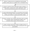
- steps S1 to S5 are the method for estimating the SOC of the battery pack in normal operation.
- the power-on initialization is performed on the battery pack
- the current I flowing through the battery pack is estimated according to the initial parameters
- the SOC of the battery pack and the polarization voltages of the battery pack are estimated according to the current I of the battery pack.
- the current I flowing through the battery pack is estimated according to the formula (1) and the initialization data of the battery pack.
- the polarization voltages PV1 and PV2 of the battery pack and the SOC of the battery pack are obtained according to the current I flowing through the battery pack and formula (2), formula (3), and formula (4).
- the charging SOC-OCV curve or the discharging SOC-OCV curve is queried according to the SOC of the battery pack such that the OCV Uocv is obtained.
- the SOC of the battery pack is estimated for the first time. Then, the preceding steps are repeated.
- a present current I is obtained according to the present polarization voltages PV1 and PV2 and the present OCV Uocv.
- the present polarization voltages PV1 and PV2 of the battery pack and the present SOC of the battery pack are obtained according to the present current I and formula (2), formula (3), and formula (4).
- the charging SOC-OCV curve or the discharging SOC-OCV curve is queried according to the present SOC such that the present OCV Uocv is obtained.
- the SOC of the battery pack is estimated for the second time. Then, the present SOC of the battery pack is continuously acquired according to the preceding cyclical steps.
- the polarization voltages are calculated through data processing on the basis that the accurate battery model is built, which may be understood as the preceding method for acquiring the polarization voltages based on the second-order RC model.
- the polarization voltage may be detected by a full rest method. A variation of the polarization voltage is detected by the full rest method. Referring to FIG. 5 , an ohmic voltage is related to a magnitude of a current. When the charge is stopped instantaneously, the ohmic voltage suddenly disappears, that is, a voltage curve in FIG. 5 is steep at point 1 and point 2. The polarization voltage is a voltage difference between point 1 and point 2.
- FIGS. 6 and 7 are graphs showing the comparison of an SOC of the battery pack obtained by the technical method in the present application with an actual SOC of the battery pack.
- FIG. 6 shows contrast curves between an estimated value and a reference value of an SOC of a 10A battery pack in a discharging process.
- a dashed line denotes the theoretical reference value of the SOC of the battery pack
- a solid line denotes the estimated value obtained with the technical solution in the present application. It can be seen from FIG. 6 that a maximum error between the reference value and the estimated value is no greater than 8% with respect to the SOC indicated by an ordinate.
- FIG. 7 shows contrast curves between an estimated value and a reference value of an SOC of a 5A battery pack in a charging process.
- FIG. 7 a solid line denotes the theoretical reference value of the SOC of the battery pack, and a dashed line denotes the estimated value obtained with the technical solution in the present application. It can be seen from FIG. 7 that a maximum error between the reference value and the estimated value is no greater than 4% with respect to the SOC indicated by an ordinate.
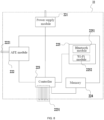
- the battery pack 20 further includes a battery management system 22 electrically connected to a cell unit 21.
- the battery management system 22 may be disposed in the battery pack 20 or may be disposed in the power tool or the charger electrically connected to the battery pack 20.
- the battery management system 22 includes a power supply module 221, an analog front-end (AFE) module 222, a controller 223, a memory 224, and a wireless communication module 225.
- the power supply module 221 is configured to power other modules and peripheral circuits in the battery management system 22.
- the power supply module 221 is electrically connected to a cell assembly 21 so that the power supply module 221 provides a working voltage for the AFE module 222, the controller 223, the memory 224, and the wireless communication module 225 by using electrical energy in the cell assembly 21.
- the AFE module 222 includes multiple interfaces 2221 which are optionally connected to one cell unit 21 or multiple cell units of the battery pack 20 and configured to sample battery pack parameters of the battery pack 20 in operation.
- the battery pack parameters include, but are not limited to, a voltage, a current, a temperature, and the like of the battery pack.
- the AFE module 222 is electrically connected to the controller 223 and configured to transmit the battery pack parameters of the battery pack 20 sampled by the interfaces 2221 to the controller 223.
- the controller 223 is configured to control working states of the other modules in the battery management system 22.
- the controller 223 is electrically connected to at least the AFE module 222 to acquire the battery pack parameters sampled by the AFE module 222.
- the controller 223 includes multiple input/output (I/O) ports 2231 which are connected to external devices for the input of relevant parameters of the battery pack 20.
- the controller 223 is also electrically connected to the wireless communication module 225 through an internal communication interface to transmit the parameters of the battery pack 20 and control a working state of the wireless communication module 225.
- the memory 224 is electrically connected to the controller 223 and configured to store the relevant parameters of the battery pack 20.
- the battery pack database involved in the SOC estimation method of the battery pack in the present application is preferably stored in the memory 224.
- the wireless communication module 225 is electrically connected to the controller 223.
- the wireless communication module 225 includes a Bluetooth module 2251 and a wireless fidelity (Wi-Fi) module 2252, and the battery management system 22 can implement wireless communication functions through the Bluetooth module 2251 and/or the Wi-Fi module 2252.
- Wi-Fi wireless fidelity
Landscapes
- General Physics & Mathematics (AREA)
- Engineering & Computer Science (AREA)
- Physics & Mathematics (AREA)
- Chemical & Material Sciences (AREA)
- Chemical Kinetics & Catalysis (AREA)
- Electrochemistry (AREA)
- General Chemical & Material Sciences (AREA)
- Manufacturing & Machinery (AREA)
- Microelectronics & Electronic Packaging (AREA)
- Power Engineering (AREA)
- Life Sciences & Earth Sciences (AREA)
- Biophysics (AREA)
- Computer Hardware Design (AREA)
- Secondary Cells (AREA)
- Charge And Discharge Circuits For Batteries Or The Like (AREA)
Abstract
Description
- The present application relates to a battery pack for powering a power tool and, in particular, to a state of charge (SOC) estimation method of the battery pack.
- A state of charge ("SOC") of a battery pack is an important basis for the charge and discharge control of a battery in a power tool, which directly affects the service life of the battery pack and the performance of the power tool. In addition, the life of the battery pack can be predicted according to the SOC. In the related art, the SOC of the battery pack is estimated mostly by an ampere-hour integration method and a model-based closed-loop estimation method such as a Kalman filter method, a sliding mode observer, and a particle filter method. Such methods require very high accuracy of a current measurement value. A relatively large current measurement error will directly lead to an inaccurate estimation result and then cause serious security problems. To improve the accuracy of SOC estimation of the battery pack, one method is to compensate for a noise effect through the real-time estimation of current and voltage measurement noise statistical characteristics, so as to achieve the relatively accurate SOC estimation of the battery pack. However, this method has a poor suppression effect on a low-frequency drift error during measurement and still requires a current sensor. Thus, the problems of a high cost, a temperature rise, and energy consumption cannot be solved and it is difficult to ensure the stability of results.
- To overcome deficiencies of the related art, the present application provides an SOC estimation method applied to a battery pack of a power tool.
- To achieve the preceding object, the present application adopts the technical solutions described below.
- In one example, a state of charge (SOC) estimation method applied to a battery pack of a power tool includes: estimating an SOC of the battery pack based on a real-time current flowing through the battery pack. The real-time current is estimated according to real-time parameters of the battery pack, at least part of the real-time parameters of the battery pack are capable of being acquired by querying a battery pack database with at least partially data preset.
- In one example, a method for building the battery pack database includes: establishing an equivalent circuit model of the battery pack; acquiring battery pack internal resistance of the battery pack under different working conditions; acquiring state of charge (SOC)-open-circuit voltage (OCV) curves of the battery pack under the different working conditions; and acquiring undetermined parameters in the equivalent circuit model.
- In one example, the equivalent circuit model is set to be a resistor-capacitor (RC) equivalent circuit model or a Warburg equivalent circuit model.
- In one example, the undetermined parameters in the equivalent circuit model include direct current (DC) internal resistance, polarization resistance, and polarization capacitance of the battery pack.
- In one example, the real-time parameters of the battery pack include an OCV, polarization voltages, a terminal voltage, battery pack internal resistance, and a temperature of the battery pack.
- In one example, the polarization voltages are acquired based on the undetermined parameters of the equivalent circuit model and the real-time current.
- In one example, the SOC-OCV curves in the battery pack database are queried such that the OCV is capable of being acquired.
- In one example, the SOC-OCV curves include charging SOC-OCV curves and discharging SOC-OCV curves.
- In one example, the battery pack internal resistance of the battery pack includes at least internal connection resistance of the battery pack and the DC internal resistance.
- In one example, the method further includes: acquiring initial parameters of the battery pack when the battery pack is powered on; estimating the real-time current of the battery pack based on the acquired initial parameters and the battery pack database; estimating polarization voltages of the battery pack based on the acquired real-time current; and estimating a present SOC of the battery pack based on the acquired polarization voltages.
- In one example, the initial parameters include a total capacity of the battery pack and initial polarization voltages, an initial OCV, and an initial SOC of the battery pack.
- In one example, the polarization voltages are estimated based on the real-time current and the battery pack database.
- In one example, an OCV of the battery pack is acquired based on the acquired SOC and the battery pack database.
- In one example, the different working conditions include at least different temperatures at which the battery pack works, different SOCs in which the battery pack works, or different numbers of cycles under which the battery pack works.
- In one example, the estimation method is applicable to at least a battery pack including no current detection device.
- With the SOC estimation method of the battery pack in the preceding example, the SOC of the battery pack can be estimated under the condition where no current detection device is provided in the battery pack, thereby reducing the cost of the battery pack. On the other hand, since no current detection hardware device needs to be provided in the battery pack, heat generated by the battery pack in charging and discharging processes can be effectively reduced. In addition, in the technical solutions proposed in the present application, the preset battery pack database is adopted. The preset battery pack database is queried such that the real-time parameters of the battery pack are indirectly acquired. Thus, the real-time current of the battery pack is estimated so that a present SOC of the battery pack is estimated.
-
-
FIG. 1 is a perspective view of a power tool system as an example in the present application; -
FIG. 2 is a perspective view of a charging system as an example in the present application; -
FIG. 3 shows an equivalent circuit model of a battery pack as an example; -
FIG. 4 is a flowchart of an SOC estimation method of a battery pack in the present application; -
FIG. 5 is a waveform diagram of a polarization voltage of a battery pack acquired by a full rest method; -
FIG. 6 is a graph showing curves of an estimated value and a reference value of an SOC of a battery pack in a discharging process; -
FIG. 7 is a graph showing curves of an estimated value and a reference value of an SOC of a battery pack in a charging process; and -
FIG. 8 is a principle diagram of a hardware device of a battery pack as an example. - The present application is described below in detail in conjunction with drawings and examples.
- It is to be understood by those of ordinary skill in the art that a relative term (such as "about", "approximately", and "substantially") used in conjunction with a quantity or a condition includes a stated value and has a meaning indicated in the context (for example, the term includes at least a degree of error associated with the measurement of a particular value, a tolerance (such as manufacturing, assembly, and use) associated with the particular value, and the like). Such term should also be considered as disclosing the range defined by the absolute values of two endpoints. The relative term may refer to an indicated value plus or minus a percentage (such as 1%, 5%, 10%, or more). Of course, a value not modified by the relative term should also be disclosed as a particular value with a tolerance.
- In the present application, unless otherwise expressly specified and limited, the term "connected to each other", "connected", or "fixed" is to be construed in a broad sense, for example, as "fixedly connected", "detachably connected", or "integrated", as "mechanically connected" or "electrically connected", as "directly connected to each other" or "indirectly connected to each other via an intermediary", or as "connected inside two components" or "an interaction relation between two elements". For those of ordinary skill in the art, specific meanings of the preceding terms in the present application may be construed according to specific situations.
- In the present application, unless otherwise expressly specified and limited, when a first feature is described as "above" or "below" a second feature, the first feature and the second feature may be in direct contact or may be in contact via another feature between the two features instead of being in direct contact. Moreover, when the first feature is "on", "above", or "over" the second feature, the first feature is right on, above, or over the second feature, the first feature is obliquely on, above, or over the second feature, or the first feature is simply at a higher level than the second feature. When the first feature is "under", "below", or "underneath" the second feature, the first feature is right under, below, or underneath the second feature, the first feature is obliquely under, below, or underneath the second feature, or the first feature is simply at a lower level than the second feature.
- As shown in
FIGS. 1 and2 , apower tool system 100 and acharging combination 200 are provided. Thepower tool system 100 includes apower tool 10 and abattery pack 20. Thebattery pack 20 is electrically connected to thepower tool 10 to provide electrical energy for thepower tool 10. Thecharging combination 200 includes thebattery pack 20 and a charger for charging thebattery pack 20. The battery pack in the present application is applicable to a handheld power tool such as an electric drill, an electric wrench, an electric screwdriver, an electric hammer drill, an electric circular saw, and a sander, an electric table tool such as a table saw, and an outdoor tool such as a lawn mower, a string trimmer, electrical shears, a pruner, and an electric saw. The battery pack is detachably connected to the preceding power tool or fixedly disposed in the preceding power tool. The battery pack in the present application is a rechargeable lithium chemistry battery such as a lithium-ion battery, particularly a cylindrical lithium-ion battery and a pouch battery which are commonly used in power tools. In some examples, the battery pack includes at least one rechargeable cell unit or multiple rechargeable cell units, which depends on different rated nominal values of the battery pack. Multiple rechargeable cell units are connected in series such that these battery packs with different nominal values can be implemented. Of course, the rechargeable cell units may be configured to be other lithium chemistry batteries based on lithium or rechargeable batteries with other chemical bases, for example, nickel-cadmium and nickel-hydrogen rechargeable batteries. Apparently, the battery pack in the present application is limited to neither the preceding power tool nor a designated nominal voltage. In fact, the teachings of the present application are applicable to any type of battery pack. - A shape of the battery pack in the present application may be, but is not limited to, a square, a barrel, a tower, or another shape. Generally, the battery pack includes a housing, at least one cell unit, an electronic device for performing internal and external control and protection measures, battery pack terminals connected to an external charger or the power tool, and a cell unit connection mechanism. Apparently, the preceding internal configurations of the battery pack such as the housing, the at least one cell unit, the electronic device for performing the internal and external control and the protection measures, the battery pack terminals connected to the external charger or the power tool, and the cell unit connection mechanism are universal configurations. Therefore, the details are not repeated in the description and the drawings.
- A state of charge estimation method of the battery pack in the present application is described below in detail in conjunction with the drawings. With the state of charge estimation method of the battery pack disclosed in the present application, a state of charge of the preceding battery pack applicable to the power tool or the charger can be efficiently and accurately estimated. For simplicity of description, the state of charge may be abbreviated as "SOC" hereinafter.
- In some examples, typically the battery pack also includes a battery management module for storing and acquiring parameters of the battery pack. Specifically, the battery management module includes at least a temperature sensor and a controller. The temperature sensor may be selected from existing temperature detection sensors such as a thermocouple, a thermal resistor, a thermistor, or a fiber Bragg grating sensor.
- The SOC estimation method of the battery pack in the present application is implemented based on a battery pack database with at least partially data preset. The battery pack database with at least partially data preset means that a part of data in the battery pack database is preset. In other words, the part of data in the battery pack database in the present application is acquired and stored through multiple tests performed on the battery pack in an offline state. Of course, the battery pack database herein also has the function of receiving data storage in an online state or data reading and storage during after-sale services. A method for building the part of data of the battery pack database is described below.
- Specifically, the battery pack database is built based on an equivalent circuit model of the cell unit of the battery pack. Common equivalent circuit models include first-order, second-order, third-order, and even n-order resistor-capacitor (RC) equivalent circuit models. The first-order RC equivalent circuit model has a relatively large error, and the accuracy of the second-order RC equivalent circuit model and the accuracy of the third-order RC equivalent circuit model are significantly improved. However, a higher order of the RC equivalent circuit model is not as good as expected. When the number of orders is greater than 5, the error of the RC equivalent circuit model increases instead. Considering model accuracy and calculation complexity, the second-order RC equivalent circuit model is selected as the equivalent circuit model of the cell unit in this example. Of course, other forms of equivalent circuit models may be selected such as a Warburg equivalent circuit model. As shown in
FIG. 3 , the second-order RC equivalent circuit model of the cell unit includes a resistor R0, a resistor R1 and a capacitor C1 which are connected in parallel to each other and then connected in series to the resistor R0, and a resistor R2 and a capacitor C2 which are connected in parallel to each other and then connected in series to the resistor R0. - In some examples, undetermined parameters of the second-order RC equivalent circuit model are acquired through an offline test and stored in the battery pack database for subsequent queries. A method for acquiring the undetermined parameters of the second-order RC equivalent circuit model is described below. Specific steps are described below.
- In S11, direct current (DC) internal resistance R0 of the battery pack under different working conditions is acquired.
- In the offline test, a voltage U1 of the present battery pack is acquired, then the battery pack is continuously discharged at a current 10, a voltage U2 of the battery pack is acquired after the battery pack is discharged for t seconds, a voltage difference between the voltage U1 and the voltage U2 is calculated, and the voltage difference is divided by the current I0 such that present DC internal resistance R0 is obtained. The preceding process is a method for acquiring the present DC internal resistance R0 of the battery pack. Specifically, in this example, the current I0 is set to 1 C, and the discharge time t is set to 1 second. Of course, those skilled in the art may make a design according to actual test conditions, and the preceding current I0 and discharge time t are not to limit the technical solution.
- In some examples, the battery pack database includes the DC internal resistance R0 of the battery pack under multiple working conditions. The preceding multiple working conditions include, but are not limited to, different temperatures, different SOCs, and different numbers of cycles. In some examples, a temperature range in the battery pack database is set to -35 °C to 60 °C. In some examples, the temperature range in the battery pack database is set to -25 °C to 50 °C. In some examples, the temperature range in the battery pack database is set to -20 °C to 45 °C. In some examples, an SOC of the battery pack is set to 5% to 100%. In some examples, the SOC of the battery pack is set to 10% to 100%. For example, a temperature of the battery pack is 10 °C and the SOC of the battery pack is 50% at present. Then, it may be known according to the preceding method for calculating the DC internal resistance R0 that the DC internal resistance R0 of the battery pack in a present state is 22 milliohms. It is to be noted that the DC internal resistance of the battery pack is related to characteristics of the battery pack, and different battery packs may have different DC internal resistance R0 at the same temperature and in the same SOC. As an example, the temperature of the battery pack is adjusted through an ambient temperature, and a present temperature of the battery pack is detected by the temperature sensor so that the battery pack can meet a present temperature requirement. The SOC of the battery pack may be calculated after a voltage of the battery pack is measured by an instrument. Of course, those skilled in the art may acquire the temperature of the battery pack and the SOC of the battery pack in another manner, which is not limited herein.
- In summary, those skilled in the art may obtain the DC internal resistance R0 of the battery pack under the multiple working conditions by at least the preceding method. The preceding working conditions include, but are not limited to, different temperatures, different SOCs, and different numbers of cycles. The preceding DC internal resistance R0 under the multiple working conditions is stored in the battery pack database for the subsequent queries.
- In S12, a state of charge (SOC)-open-circuit voltage (OCV) curve of the battery pack is acquired.
- The preceding SOC-OCV curve includes a charging SOC-OCV curve and a discharging SOC-OCV curve. In some examples, charging SOC-OCV curves and discharging SOC-OCV curves of the battery pack at different temperatures are acquired and stored in the battery pack database. In some examples, charging SOC-OCV curves and discharging SOC-OCV curves of the battery pack under different numbers of cycles are acquired and also stored in the battery pack database for the subsequent queries.
- A method for acquiring the charging SOC-OCV curve and the discharging SOC-OCV curve is described below in detail.
- As an example, a method for acquiring the discharging SOC-OCV curve is described below.
- In S121, the battery pack is charged to 100%.
- In S122, the fully charged battery pack is left at rest, and a battery terminal voltage after a rest is measured.
- In S123, the battery after the rest is discharged, and in the discharging process, a real-time SOC of the battery pack is obtained by an ampere-hour integration method.
- In S124, when the real-time SOC of the battery pack decreases by 1%, the battery pack stops being discharged and is left at rest, and the battery terminal voltage after the rest is measured, which is just an OCV corresponding to a present SOC of 99%.
- In S125, steps S123 and S124 are repeated, OCVs corresponding to SOCs with an interval of 1% are recorded until the battery terminal voltage drops to a cut-off voltage, the battery pack stops being discharged and is left at rest, and the battery terminal voltage after the rest is measured, which is just a corresponding OCV when the SOC of the battery pack is 0%.
- The discharging SOC-OCV curve of the battery pack can be acquired by the preceding method. In this example, the battery pack is controlled to stop being discharged and be left at rest each time the SOC of the battery pack decreases by 1% in the discharging process such that the corresponding OCVs are acquired. It is to be noted that those skilled in the art may set that the SOC of the battery pack decreases by 2%, 5%, or other specific values each time in the offline test, which is not limited herein.
- A method for acquiring charging SOC-OCV curves and discharging SOC-OCV curves of the battery pack under multiple working conditions is described below.
- In some examples, the battery pack database includes charging SOC-OCV curves and discharging SOC-OCV curves of the battery packs at different temperatures and under different numbers of cycles. In some examples, the preceding temperature range is set to -35 °C to 60 °C. In some examples, the temperature range is set to -10 °C to 55 °C. In some examples, a range of the preceding number of cycles is set to 0 to 100. In some examples, the range of the number of cycles is set to 101 to 200. In some examples, the range of the number of cycles is set to 201 to 500. The preceding cycle range should be set according to the characteristics of the present battery pack, which is not limited herein.
- A method for acquiring charging SOC-OCV curves and discharging SOC-OCV curves of the battery pack in the offline state at different temperatures and under different numbers of cycles is described below.
- In S13, parameters of the cell unit and parameters of the battery pack are acquired.
- In addition to the DC internal resistance R0, the cell unit also generates other forms of impedance in a charging or discharging process of the cell unit. Referring to
FIG. 3 , the second-order RC model of the cell unit also involves polarization resistance R1, polarization resistance R2, polarization capacitance C1, and polarization capacitance C2. Specifically, specific values of the polarization resistance R1, the polarization resistance R2, the polarization capacitance C1, and the polarization capacitance C2 are acquired in the following manner: different excitation signals may be added to the battery pack from the outside such that the polarization resistance R1, the polarization resistance R2, the polarization capacitance C1, and the polarization capacitance C2 of the present cell unit are calculated. It is to be noted that the polarization resistance R1, the polarization resistance R2, the polarization capacitance C1, and the polarization capacitance C2 of the cell unit vary with the attenuation of charging and discharging capabilities of the cell unit, but the variations are negligible in one charging or discharging process. The polarization resistance R1, the polarization resistance R2, the polarization capacitance C1, and the polarization capacitance C2 satisfy the law that they are stable in a short term and vary in a long term. Finally, the parameters of the cell unit including, but not limited to, the polarization resistance R1, the polarization resistance R2, the polarization capacitance C1, and the polarization capacitance C2 are stored in the database for the subsequent queries. - At present, at least two or more cell units are typically disposed in an existing battery pack. In some examples, two cell units connected in series to each other are disposed in the battery pack. In some other examples, four cell units connected in series to each other are disposed in the battery pack. When the multiple cell units in the battery pack are connected in series or in parallel, internal resistance of the battery pack includes not only internal resistance of the cell units but also internal connection resistance between the multiple cell units and other forms of internal resistance, which are collectively referred to as internal connection resistance. To further improve the accuracy of the SOC estimation method of the battery pack, the internal connection resistance of the battery pack is also added to the battery pack database in this example. The internal connection resistance of the battery pack is acquired by a method for identifying the parameters of the battery pack, which is similar to the preceding method for acquiring the parameters of the cell unit.
- The method and steps for building the database are described above. It is to be noted that the preceding battery pack database is built in the offline state. That is, relevant parameters of the battery pack are acquired through multiple tests, which are valid and real. Specifically, the relevant parameters in the battery pack database include, but are not limited to, the DC internal resistance R0, the charging SOC-OCV curves, the discharging SOC-OCV curves, the parameters of the equivalent model of the cell unit, and the internal connection resistance of the battery pack. When the temperature of the battery pack varies, the DC internal resistance R0 of the battery pack also varies. When the SOC of the battery pack varies, the DC internal resistance R0 also varies. Therefore, in the preceding battery pack database, the DC internal resistance R0 varies with the temperature of the battery pack, the SOC of the battery pack, or the number of cycles of the battery pack. The charging SOC-OCV curves are obtained under different working conditions of the battery pack. For example, when the temperature of the battery pack varies, the charging SOC-OCV curve of the battery pack and the discharging SOC-OCV curve of the battery pack vary accordingly. When the number of cycles of the battery pack varies, the charging SOC-OCV curve of the battery pack and the discharging SOC-OCV curve of the battery pack also vary accordingly. Therefore, in the database, the charging SOC-OCV curve of the battery pack and the discharging SOC-OCV curve of the battery pack vary with the temperature of the battery pack or the number of cycles of the battery pack. Of course, those skilled in the art may also add other parameters related to the battery pack to the battery pack database.
- The method for building the battery pack database is described in detail above. How to estimate the SOC of the battery pack based on the built battery pack database in the present application is described below in detail.
- In S1, a setting for power-on initialization of the battery pack is performed.
- Initial parameters of the battery pack at a power-on moment are acquired. In this example, the initial parameters include, but are not limited to, the number of cell units connected in series or in parallel, a total capacity of the battery pack, and initial polarization voltages of the battery pack. Of course, the preceding power-on moment includes a power-on moment when the battery pack is charged and a power-on moment when the battery pack is discharged. The number of cell units connected in series or in parallel in the battery pack and the total capacity of the battery pack are the characteristics of the battery pack and may be read directly from the battery pack. The polarization voltages of the battery pack in this step may be queried according to the parameters of the cell unit and the parameters of the battery pack in the battery pack database, and an acquisition method thereof is described in detail below.
- Then, an initial OCV of the battery pack and an initial SOC of the battery pack also need to be acquired in the setting for power-on initialization. Specifically, the initial OCV of the battery pack may be directly measured and acquired. The initial SOC of the battery pack may be acquired according to historical data. The preceding historical data refers to that the battery pack has the function of storing a present SOC each time the battery pack is powered off. Of course, if no historical data can be queried, the charging SOC-OCV curve or the discharging SOC-OCV curve in the database may be queried according to the initial OCV acquired currently such that the initial SOC is obtained.
- In S2, a current I of the battery pack after being powered on is estimated.
- After the setting for power-on initialization of the battery pack is completed, it is determined whether the battery pack is currently in a charged state or a discharged state so as to determine whether the charging SOC-OCV curve or the discharging SOC-OCV curve is queried subsequently. The current I may be calculated through the following formula:

- In S3, the polarization voltages of the battery pack are estimated.
- When a current passes through a battery, a potential deviation from equilibrium potential is referred to as electrode polarization. The polarization voltage is an important parameter reflecting the intensity of a chemical reaction inside the battery. When the battery pack is in normal operation, that is, in the charging or discharging process, the polarization voltages of the battery pack also need to be estimated cyclically. In this example, the polarization voltages PV1 and PV2 are estimated according to the following formulas:


- In S4, the SOC of the battery pack is estimated.
- After the current I of the battery pack is known, the SOC of the battery pack may be obtained according to the following formula:

- In S5, a real-time OCV Uocv of the battery pack is estimated.
- The charging SOC-OCV curve or the discharging SOC-OCV curve in the database is queried according to the SOC of the battery pack estimated in step S4 such that the real-time OCV Uocv of the battery pack is estimated.
- In summary, steps S1 to S5 are the method for estimating the SOC of the battery pack in normal operation. As shown in
FIG. 4 , the power-on initialization is performed on the battery pack, the current I flowing through the battery pack is estimated according to the initial parameters, and the SOC of the battery pack and the polarization voltages of the battery pack are estimated according to the current I of the battery pack. Specifically, the current I flowing through the battery pack is estimated according to the formula (1) and the initialization data of the battery pack. Further, the polarization voltages PV1 and PV2 of the battery pack and the SOC of the battery pack are obtained according to the current I flowing through the battery pack and formula (2), formula (3), and formula (4). In addition, the charging SOC-OCV curve or the discharging SOC-OCV curve is queried according to the SOC of the battery pack such that the OCV Uocv is obtained. Thus, the SOC of the battery pack is estimated for the first time. Then, the preceding steps are repeated. A present current I is obtained according to the present polarization voltages PV1 and PV2 and the present OCV Uocv. Further, the present polarization voltages PV1 and PV2 of the battery pack and the present SOC of the battery pack are obtained according to the present current I and formula (2), formula (3), and formula (4). In addition, the charging SOC-OCV curve or the discharging SOC-OCV curve is queried according to the present SOC such that the present OCV Uocv is obtained. Thus, the SOC of the battery pack is estimated for the second time. Then, the present SOC of the battery pack is continuously acquired according to the preceding cyclical steps. - In the preceding example, the polarization voltages are calculated through data processing on the basis that the accurate battery model is built, which may be understood as the preceding method for acquiring the polarization voltages based on the second-order RC model. In some other examples, the polarization voltage may be detected by a full rest method. A variation of the polarization voltage is detected by the full rest method. Referring to
FIG. 5 , an ohmic voltage is related to a magnitude of a current. When the charge is stopped instantaneously, the ohmic voltage suddenly disappears, that is, a voltage curve inFIG. 5 is steep atpoint 1 andpoint 2. The polarization voltage is a voltage difference betweenpoint 1 andpoint 2. -
FIGS. 6 and7 are graphs showing the comparison of an SOC of the battery pack obtained by the technical method in the present application with an actual SOC of the battery pack.FIG. 6 shows contrast curves between an estimated value and a reference value of an SOC of a 10A battery pack in a discharging process. InFIG. 6 , a dashed line denotes the theoretical reference value of the SOC of the battery pack, and a solid line denotes the estimated value obtained with the technical solution in the present application. It can be seen fromFIG. 6 that a maximum error between the reference value and the estimated value is no greater than 8% with respect to the SOC indicated by an ordinate.FIG. 7 shows contrast curves between an estimated value and a reference value of an SOC of a 5A battery pack in a charging process. In -
FIG. 7 , a solid line denotes the theoretical reference value of the SOC of the battery pack, and a dashed line denotes the estimated value obtained with the technical solution in the present application. It can be seen fromFIG. 7 that a maximum error between the reference value and the estimated value is no greater than 4% with respect to the SOC indicated by an ordinate. - In some examples, as shown in
FIG. 8 , thebattery pack 20 further includes abattery management system 22 electrically connected to acell unit 21. Specifically, thebattery management system 22 may be disposed in thebattery pack 20 or may be disposed in the power tool or the charger electrically connected to thebattery pack 20. In some examples, thebattery management system 22 includes apower supply module 221, an analog front-end (AFE)module 222, acontroller 223, amemory 224, and awireless communication module 225. Thepower supply module 221 is configured to power other modules and peripheral circuits in thebattery management system 22. - The
power supply module 221 is electrically connected to acell assembly 21 so that thepower supply module 221 provides a working voltage for theAFE module 222, thecontroller 223, thememory 224, and thewireless communication module 225 by using electrical energy in thecell assembly 21. - The
AFE module 222 includesmultiple interfaces 2221 which are optionally connected to onecell unit 21 or multiple cell units of thebattery pack 20 and configured to sample battery pack parameters of thebattery pack 20 in operation. Specifically, the battery pack parameters include, but are not limited to, a voltage, a current, a temperature, and the like of the battery pack. TheAFE module 222 is electrically connected to thecontroller 223 and configured to transmit the battery pack parameters of thebattery pack 20 sampled by theinterfaces 2221 to thecontroller 223. - The
controller 223 is configured to control working states of the other modules in thebattery management system 22. Thecontroller 223 is electrically connected to at least theAFE module 222 to acquire the battery pack parameters sampled by theAFE module 222. In some examples, thecontroller 223 includes multiple input/output (I/O)ports 2231 which are connected to external devices for the input of relevant parameters of thebattery pack 20. In some examples, thecontroller 223 is also electrically connected to thewireless communication module 225 through an internal communication interface to transmit the parameters of thebattery pack 20 and control a working state of thewireless communication module 225. - The
memory 224 is electrically connected to thecontroller 223 and configured to store the relevant parameters of thebattery pack 20. As an example, the battery pack database involved in the SOC estimation method of the battery pack in the present application is preferably stored in thememory 224. - The
wireless communication module 225 is electrically connected to thecontroller 223. - In some examples, the
wireless communication module 225 includes aBluetooth module 2251 and a wireless fidelity (Wi-Fi)module 2252, and thebattery management system 22 can implement wireless communication functions through theBluetooth module 2251 and/or the Wi-Fi module 2252. - It is to be noted that the preceding are only preferred examples of the present application and the technical principles used therein. It is to be understood by those skilled in the art that the present application is not limited to the examples described herein. For those skilled in the art, various apparent modifications, adaptations, and substitutions can be made without departing from the scope of the present application.
Claims (15)
- A state of charge (SOC) estimation method applied to a battery pack (20) of a power tool (100), comprising:estimating an SOC of the battery pack based on a real-time current flowing through the battery pack;wherein the real-time current is estimated according to real-time parameters of the battery pack, at least part of the real-time parameters of the battery pack are capable of being acquired by querying a battery pack database with at least partially data preset.
- The method according to claim 1, wherein a method for building the battery pack database comprises: establishing an equivalent circuit model of the battery pack; acquiring battery pack internal resistance of the battery pack under different working conditions; acquiring state of charge (SOC)-open-circuit voltage (OCV) curves of the battery pack under the different working conditions; and acquiring undetermined parameters in the equivalent circuit model.
- The method according to claim 2, wherein the equivalent circuit model is set to be a resistor-capacitor (RC) equivalent circuit model or a Warburg equivalent circuit model.
- The method according to claim 2, wherein the undetermined parameters in the equivalent circuit model comprise direct current (DC) internal resistance, polarization resistance, and polarization capacitance of the battery pack.
- The method according to claim 4, wherein the real-time parameters of the battery pack comprise an OCV, polarization voltages, a terminal voltage, battery pack internal resistance, and a temperature of the battery pack.
- The method according to claim 5, wherein the polarization voltages are acquired based on the undetermined parameters of the equivalent circuit model and the real-time current.
- The method according to claim 5, wherein the SOC-OCV curves in the battery pack database are queried such that the OCV is capable of being acquired.
- The method according to claim 7, wherein the SOC-OCV curves comprise charging SOC-OCV curves and discharging SOC-OCV curves.
- The method according to claim 5, wherein the battery pack internal resistance of the battery pack comprises at least internal connection resistance of the battery pack and the DC internal resistance.
- The method according to claim 1, comprising: acquiring initial parameters of the battery pack when the battery pack is powered on; estimating the real-time current of the battery pack based on the acquired initial parameters and the battery pack database; estimating polarization voltages of the battery pack based on the acquired real-time current; and estimating a present SOC of the battery pack based on the acquired polarization voltages.
- The method according to claim 10, wherein the initial parameters comprise a total capacity of the battery pack and initial polarization voltages, an initial OCV, and an initial SOC of the battery pack.
- The method according to claim 10, wherein the polarization voltages are estimated based on the real-time current and the battery pack database.
- The method according to claim 10, wherein an OCV of the battery pack is acquired based on the acquired SOC and the battery pack database.
- The method according to claim 2, wherein the different working conditions comprise at least different temperatures at which the battery pack works, different SOCs in which the battery pack works, or different numbers of cycles under which the battery pack works.
- The method according to claim 1, wherein the estimation method is applicable to at least a battery pack comprising no current detection device.
Applications Claiming Priority (1)
| Application Number | Priority Date | Filing Date | Title |
|---|---|---|---|
| CN202111632544 | 2021-12-28 |
Publications (1)
| Publication Number | Publication Date |
|---|---|
| EP4206709A1 true EP4206709A1 (en) | 2023-07-05 |
Family
ID=84363159
Family Applications (1)
| Application Number | Title | Priority Date | Filing Date |
|---|---|---|---|
| EP22209534.1A Ceased EP4206709A1 (en) | 2021-12-28 | 2022-11-25 | State of charge estimation method |
Country Status (5)
| Country | Link |
|---|---|
| US (1) | US12571846B2 (en) |
| EP (1) | EP4206709A1 (en) |
| CN (1) | CN116359761A (en) |
| AU (1) | AU2022279550A1 (en) |
| CA (1) | CA3185300A1 (en) |
Cited By (1)
| Publication number | Priority date | Publication date | Assignee | Title |
|---|---|---|---|---|
| US12571846B2 (en) | 2021-12-28 | 2026-03-10 | Nanjing Chervon Industry Co., Ltd. | Battery pack and state of charge estimation method thereof |
Families Citing this family (5)
| Publication number | Priority date | Publication date | Assignee | Title |
|---|---|---|---|---|
| JP2024178006A (en) * | 2023-06-12 | 2024-12-24 | キヤノン株式会社 | Electronic device, control method thereof, and program |
| CN116979185B (en) * | 2023-08-04 | 2024-05-17 | 湖南恩智测控技术有限公司 | A temperature adjustment method and system for simulating battery based on battery simulator |
| CN117538759B (en) * | 2024-01-10 | 2024-03-19 | 清华四川能源互联网研究院 | Method for obtaining direct-current internal resistance high flux of lithium ion battery |
| CN119001472B (en) * | 2024-10-23 | 2024-12-27 | 四川开物信息技术有限公司 | Battery pack monitoring method and system based on Bluetooth low energy technology |
| CN119535243B (en) * | 2025-01-23 | 2025-03-28 | 上海泰矽微电子有限公司 | Online identification method and device for battery impedance, electronic equipment and medium |
Citations (6)
| Publication number | Priority date | Publication date | Assignee | Title |
|---|---|---|---|---|
| US20050269991A1 (en) * | 2002-07-12 | 2005-12-08 | Masahiko Mitsui | Battery state-of-charge estimator |
| WO2015056964A1 (en) * | 2013-10-14 | 2015-04-23 | 주식회사 엘지화학 | Apparatus for estimating state of hybrid secondary battery and method therefor |
| US20190064276A1 (en) * | 2016-02-01 | 2019-02-28 | Denso Corporation | Battery state estimating device |
| CN109752660A (en) * | 2019-01-23 | 2019-05-14 | 孟锦豪 | A kind of battery charge state estimation method of Current Sensorless |
| CN111190109A (en) * | 2020-01-07 | 2020-05-22 | 西北工业大学 | Current-sensor-free lithium battery state of charge estimation method |
| US20210364574A1 (en) * | 2020-11-06 | 2021-11-25 | Beijing Institute Of Technology | Intelligent battery and state-of-charge online estimation method and applications thereof |
Family Cites Families (11)
| Publication number | Priority date | Publication date | Assignee | Title |
|---|---|---|---|---|
| US10094881B2 (en) | 2013-02-28 | 2018-10-09 | Dongguan Cellwise Microelectronics Co., Ltd. | Battery fuel gauging system |
| CN103728530A (en) * | 2013-12-20 | 2014-04-16 | 惠州市亿能电子有限公司 | Method for detecting connection quality among unit batteries of batter pack |
| IT201700058171A1 (en) | 2017-05-29 | 2018-11-29 | Magneti Marelli Spa | Method of estimating the current and state of charge of a battery pack or cell, without direct current detection in operating conditions |
| US10677848B2 (en) * | 2017-06-02 | 2020-06-09 | Total S.A. | Apparatus, circuit model, and method for battery modelling |
| US10312699B2 (en) * | 2017-07-31 | 2019-06-04 | Robert Bosch Gmbh | Method and system for estimating battery open cell voltage, state of charge, and state of health during operation of the battery |
| DE102018220251A1 (en) * | 2018-11-26 | 2020-05-28 | Robert Bosch Gmbh | Method and device for assessing the health status of a removable battery |
| CN109856556A (en) | 2019-03-21 | 2019-06-07 | 南京工程学院 | A kind of power battery SOC estimation method |
| US20210173012A1 (en) * | 2019-12-04 | 2021-06-10 | Robert Bosch Gmbh | Method and system for estimation of open circuit voltage of a battery cell |
| MX2021014829A (en) * | 2020-12-11 | 2022-07-12 | Techtronic Cordless Gp | METHOD TO ESTIMATE THE STATE OF CHARGE OF A BATTERY PACK. |
| CN113514703B (en) * | 2021-09-14 | 2021-12-07 | 苏州华兴源创科技股份有限公司 | Capacitance measuring circuit and measuring method |
| EP4206709A1 (en) | 2021-12-28 | 2023-07-05 | Nanjing Chervon Industry Co., Ltd. | State of charge estimation method |
-
2022
- 2022-11-25 EP EP22209534.1A patent/EP4206709A1/en not_active Ceased
- 2022-12-02 US US18/073,687 patent/US12571846B2/en active Active
- 2022-12-02 AU AU2022279550A patent/AU2022279550A1/en active Pending
- 2022-12-15 CA CA3185300A patent/CA3185300A1/en active Pending
- 2022-12-16 CN CN202211624456.6A patent/CN116359761A/en active Pending
Patent Citations (6)
| Publication number | Priority date | Publication date | Assignee | Title |
|---|---|---|---|---|
| US20050269991A1 (en) * | 2002-07-12 | 2005-12-08 | Masahiko Mitsui | Battery state-of-charge estimator |
| WO2015056964A1 (en) * | 2013-10-14 | 2015-04-23 | 주식회사 엘지화학 | Apparatus for estimating state of hybrid secondary battery and method therefor |
| US20190064276A1 (en) * | 2016-02-01 | 2019-02-28 | Denso Corporation | Battery state estimating device |
| CN109752660A (en) * | 2019-01-23 | 2019-05-14 | 孟锦豪 | A kind of battery charge state estimation method of Current Sensorless |
| CN111190109A (en) * | 2020-01-07 | 2020-05-22 | 西北工业大学 | Current-sensor-free lithium battery state of charge estimation method |
| US20210364574A1 (en) * | 2020-11-06 | 2021-11-25 | Beijing Institute Of Technology | Intelligent battery and state-of-charge online estimation method and applications thereof |
Non-Patent Citations (1)
| Title |
|---|
| KUPPER MARTIN ET AL: "Current and State of Charge Estimation of Lithium-Ion Battery Packs Using Distributed Fractional Extended Kalman Filters", 2019 IEEE CONFERENCE ON CONTROL TECHNOLOGY AND APPLICATIONS (CCTA), IEEE, 19 August 2019 (2019-08-19), pages 462 - 469, XP033645682, DOI: 10.1109/CCTA.2019.8920558 * |
Cited By (1)
| Publication number | Priority date | Publication date | Assignee | Title |
|---|---|---|---|---|
| US12571846B2 (en) | 2021-12-28 | 2026-03-10 | Nanjing Chervon Industry Co., Ltd. | Battery pack and state of charge estimation method thereof |
Also Published As
| Publication number | Publication date |
|---|---|
| CN116359761A (en) | 2023-06-30 |
| AU2022279550A1 (en) | 2023-07-13 |
| US12571846B2 (en) | 2026-03-10 |
| US20230204670A1 (en) | 2023-06-29 |
| CA3185300A1 (en) | 2023-06-28 |
Similar Documents
| Publication | Publication Date | Title |
|---|---|---|
| EP4206709A1 (en) | State of charge estimation method | |
| EP2841956B1 (en) | An imbedded chip for battery applications | |
| TWI708068B (en) | Method and apparatus for determining the state of health and state of charge of lithium sulfur batteries | |
| TWI510799B (en) | Apparatus and method for estimating state of charging of battery | |
| CN112534283B (en) | Battery management system, battery management method, battery pack and electric vehicle | |
| CN107533105B (en) | Lithium ion battery state of charge estimation method and device | |
| CN1883095B (en) | Portable power kit with its own power supply | |
| CN113777501B (en) | SOH estimation method of battery module | |
| EP2375541A2 (en) | Battery powered tool | |
| Mingant et al. | EIS measurements for determining the SOC and SOH of Li-ion batteries | |
| CN102662148A (en) | On-line feedback battery state of charge (SOC) predicting method | |
| CN111190109B (en) | Current-sensor-free lithium battery state of charge estimation method | |
| KR20220034543A (en) | Method for estimating state of charge of battery | |
| CN112305426A (en) | A Power State Estimation System for Li-ion Battery under Multiple Constraints | |
| CN111707947B (en) | Method and device for online battery capacity identification and iterative calibration | |
| Shamsi | Analysis of an electric Equivalent Circuit Model of a Li-Ion battery to develop algorithms for battery states estimation. | |
| Skoog | Electro-thermal modeling of high-performance lithium-ion energy storage systems including reversible entropy heat | |
| CN119716615B (en) | SOH calibration method, device, equipment and medium | |
| Nirmala et al. | Iot Based Battery Monitoring System For Solar PV Fed DC-DC Converter | |
| TWI869147B (en) | Method and system for identifying battery types | |
| CN112858913B (en) | Method for calculating remaining battery power based on variable parameter first-order RC model | |
| Havelka et al. | External Monitoring System for Battery Condition and State of Health of Lithium-Ion Batteries | |
| Shrivastava | Real Time Estimation and Monitoring of Battery Parameters | |
| Thompson | Modeling and exploring battery management strategies for use of LiCoO2 lithium polymer cells in cold climates | |
| CN117452230A (en) | A SOC calibration algorithm based on kalman filter multi-sensor fusion |
Legal Events
| Date | Code | Title | Description |
|---|---|---|---|
| PUAI | Public reference made under article 153(3) epc to a published international application that has entered the european phase |
Free format text: ORIGINAL CODE: 0009012 |
|
| STAA | Information on the status of an ep patent application or granted ep patent |
Free format text: STATUS: THE APPLICATION HAS BEEN PUBLISHED |
|
| AK | Designated contracting states |
Kind code of ref document: A1 Designated state(s): AL AT BE BG CH CY CZ DE DK EE ES FI FR GB GR HR HU IE IS IT LI LT LU LV MC ME MK MT NL NO PL PT RO RS SE SI SK SM TR |
|
| STAA | Information on the status of an ep patent application or granted ep patent |
Free format text: STATUS: REQUEST FOR EXAMINATION WAS MADE |
|
| 17P | Request for examination filed |
Effective date: 20231129 |
|
| RBV | Designated contracting states (corrected) |
Designated state(s): AL AT BE BG CH CY CZ DE DK EE ES FI FR GB GR HR HU IE IS IT LI LT LU LV MC ME MK MT NL NO PL PT RO RS SE SI SK SM TR |
|
| STAA | Information on the status of an ep patent application or granted ep patent |
Free format text: STATUS: EXAMINATION IS IN PROGRESS |
|
| 17Q | First examination report despatched |
Effective date: 20240222 |
|
| STAA | Information on the status of an ep patent application or granted ep patent |
Free format text: STATUS: THE APPLICATION HAS BEEN REFUSED |
|
| 18R | Application refused |
Effective date: 20251023 |