EP4206646A1 - Similarity simulation test device for solid-liquid coupling of coal and rock mass, and method for using the device - Google Patents
Similarity simulation test device for solid-liquid coupling of coal and rock mass, and method for using the device Download PDFInfo
- Publication number
- EP4206646A1 EP4206646A1 EP22187729.3A EP22187729A EP4206646A1 EP 4206646 A1 EP4206646 A1 EP 4206646A1 EP 22187729 A EP22187729 A EP 22187729A EP 4206646 A1 EP4206646 A1 EP 4206646A1
- Authority
- EP
- European Patent Office
- Prior art keywords
- loading
- lateral
- carrying
- frame
- water
- Prior art date
- Legal status (The legal status is an assumption and is not a legal conclusion. Google has not performed a legal analysis and makes no representation as to the accuracy of the status listed.)
- Granted
Links
Images







Classifications
-
- G—PHYSICS
- G01—MEASURING; TESTING
- G01N—INVESTIGATING OR ANALYSING MATERIALS BY DETERMINING THEIR CHEMICAL OR PHYSICAL PROPERTIES
- G01N3/00—Investigating strength properties of solid materials by application of mechanical stress
- G01N3/08—Investigating strength properties of solid materials by application of mechanical stress by applying steady tensile or compressive forces
-
- G—PHYSICS
- G01—MEASURING; TESTING
- G01N—INVESTIGATING OR ANALYSING MATERIALS BY DETERMINING THEIR CHEMICAL OR PHYSICAL PROPERTIES
- G01N15/00—Investigating characteristics of particles; Investigating permeability, pore-volume or surface-area of porous materials
- G01N15/08—Investigating permeability, pore-volume, or surface area of porous materials
- G01N15/082—Investigating permeability by forcing a fluid through a sample
- G01N15/0826—Investigating permeability by forcing a fluid through a sample and measuring fluid flow rate, i.e. permeation rate or pressure change
-
- G—PHYSICS
- G01—MEASURING; TESTING
- G01N—INVESTIGATING OR ANALYSING MATERIALS BY DETERMINING THEIR CHEMICAL OR PHYSICAL PROPERTIES
- G01N3/00—Investigating strength properties of solid materials by application of mechanical stress
- G01N3/02—Details
-
- G—PHYSICS
- G01—MEASURING; TESTING
- G01N—INVESTIGATING OR ANALYSING MATERIALS BY DETERMINING THEIR CHEMICAL OR PHYSICAL PROPERTIES
- G01N2203/00—Investigating strength properties of solid materials by application of mechanical stress
- G01N2203/0001—Type of application of the stress
- G01N2203/0003—Steady
-
- G—PHYSICS
- G01—MEASURING; TESTING
- G01N—INVESTIGATING OR ANALYSING MATERIALS BY DETERMINING THEIR CHEMICAL OR PHYSICAL PROPERTIES
- G01N2203/00—Investigating strength properties of solid materials by application of mechanical stress
- G01N2203/003—Generation of the force
- G01N2203/0032—Generation of the force using mechanical means
-
- G—PHYSICS
- G01—MEASURING; TESTING
- G01N—INVESTIGATING OR ANALYSING MATERIALS BY DETERMINING THEIR CHEMICAL OR PHYSICAL PROPERTIES
- G01N2203/00—Investigating strength properties of solid materials by application of mechanical stress
- G01N2203/003—Generation of the force
- G01N2203/0042—Pneumatic or hydraulic means
Definitions
- the present invention relates to the field of coal and, more particularly, to a test device for conducting a similarity simulation test on solid-liquid coupling of coal and rock mass, and a method for using the test device.
- a similar material simulation test is a technical means to reproduce an engineering site in a laboratory based on geological conditions, force conditions and boundary conditions of the engineering site, using similarity theories such as geometric similarity, mechanical similarity and physical parameter similarity, and is widely used in mining engineering, civil engineering, geotechnical engineering and other engineering fields.
- invention patent CN202110000142.8 discloses a solid-liquid coupling experiment device and experiment method, in which the device is mainly used to analyze a seepage process of coal or rock specimens, focusing on the analysis of loading and unloading experiments conducted on small-scale coal or rock specimens, but the device cannot carry out similarity simulation tests on large-scale coal and rock mass.
- Some researchers have improved traditional similarity simulation test systems, to meet the basic requirements of similarity simulation tests on solid-liquid coupling.
- invention patent CN201910567055.3 discloses a three-dimensional solid-liquid coupling similar simulation system and method for coal seam excavation, but the system is not much different from the traditional similarity simulation test system for coal seam excavation, and it is difficult to realize adjustment of water pressure and mine pressure.
- invention patent CN201910513853.8 discloses a device and method for performing three-dimensional solid-liquid coupling similarity simulation of water accumulation in a coal mined-out area, but the system cannot realize loading and unloading change control, and it is difficult to simulate the influence of water pressure and mine pressure changes on the strength of coal and rock mass.
- Invention patent CN201811416280.9 discloses a solid-liquid coupling three-dimensional nondestructive monitoring system and method for mining overburden rocks, in which the system mainly simulates a seepage pattern of an upper rock layer at a mining site, but cannot realize simulation of stress, seepage, damage and destroy of the coal and rock mass under the action of solid-liquid coupling.
- the present invention proposes a similarity simulation test device for solid-liquid coupling of coal and rock mass, and a method for using the similarity simulation test device.
- the similarity simulation test device can adjust water pressure and mine pressure to which the coal and rock mass is subjected, and realize similarity simulation test analysis of stress, seepage, damage and destroy of the coal and rock mass under the combined action of water pressure and mine pressure.
- a similarity simulation test device for solid-liquid coupling of coal and rock mass includes: a test body carrying frame, a lateral carrying frame, a first loading mechanism, a second vertical loading mechanism, a third lateral loading mechanism, a hydraulic jack, and a stabilizing support beam.
- the similarity simulation test device for solid-liquid coupling of the coal and rock mass consists of one test body carrying frame, two lateral carrying frames, one first loading mechanism, one second vertical loading mechanism, two third lateral loading mechanisms, two hydraulic jacks, and one stabilizing support beam. Both ends of the first loading mechanism are connected to respective first ends of the two hydraulic jacks, and respective second ends of the two hydraulic jacks are connected to the test body carrying frame.
- the lateral carrying frames are connected to the test body carrying frame, the second vertical loading mechanism, the third lateral loading mechanisms, and the stabilizing support beam. Both ends of the second vertical loading mechanism are connected to the two lateral carrying frames, correspondingly.
- the third lateral loading mechanisms are connected to the two lateral carrying frames. Both ends of the stabilizing support beam are connected to the two lateral carrying frames, correspondingly.
- the test body carrying frame includes: a sealing back plate, a lateral sealing plate, a water baffle, a sealing bottom plate, a bearing bottom plate, a water channel, a water collection bin, a first water outlet pipe, a second water outlet pipe, a support leg, a first connection trunnion, a second connection trunnion, a third connection trunnion, and a fourth connection trunnion.
- the sealing back plate is fixedly connected to the lateral sealing plate and the sealing bottom plate.
- the bearing bottom plate is fixedly connected to the sealing bottom plate, and the bearing bottom plate is slightly lower than the sealing bottom plate to form a step.
- the bearing bottom plate has a water channel, and the water channel is adjacent to the water baffle.
- the water baffle is configured to stop seeping water from flowing out of a test bench and allow the seeping water to flow into the water collection bin through the water channel.
- the water collection bin is configured to collect water that seeps out of the coal and rock mass materials during a test.
- the first water outlet pipe is configured to monitor changes in water pressure and discharge the water at the end of the test.
- the second water outlet pipe is configured to discharge the water stored in the water collection bin.
- the first connection trunnion is connected to the first end of the hydraulic jack.
- the second connection trunnion, the third connection trunnion, and the fourth connection trunnion are connected to the lateral carrying frame, forming a stable test bench.
- the lateral carrying frame includes a carrying-frame support side plate, a carrying-frame guide hole, a carrying-frame threaded hole, a carrying-frame first connection trunnion, a carrying-frame second connection trunnion, a carrying-frame third connection trunnion, and a carrying-frame fourth connection trunnion.
- the carrying-frame first connection trunnion is connected to the second connection trunnion.
- the carrying-frame second connection trunnion is connected to the fourth connection trunnion.
- the carrying-frame third connection trunnion is connected to the third connection trunnion.
- the carrying-frame fourth connection trunnion is connected to one end of the stabilizing support beam.
- the first loading mechanism includes a first loading pressure plate, a first loading rib plate, a water injection pipe, and a first loading connection trunnion; and the first loading connection trunnion is connected to the second end of the hydraulic jack.
- the second vertical loading mechanism includes: a second loading pressure plate, a second loading fixing plate, a second loading guide pillar, a second loading bolt, a second loading connection trunnion.
- the second loading pressure plate is fixedly connected to the second loading guide pillar
- the second loading fixing plate has a guide hole
- the second loading guide pillar is movable up and down along the guide hole.
- the second loading fixing plate has a threaded hole, and the second loading bolt applies a load to the second loading fixing plate through the threaded hole.
- the second loading connection trunnion is connected to the carrying-frame second connection trunnion.
- the third lateral loading mechanism includes a third lateral loading pressure plate, a third lateral loading guide pillar, and a third lateral loading bolt; the third lateral loading guide pillar is fixedly connected to the third lateral loading pressure plate; and the third lateral loading bolt applies a load to the third lateral loading pressure plate through the carrying-frame threaded hole.
- a method for using the similarity simulation test device for solid-liquid coupling of coal and rock mass includes:
- a similarity simulation test device for solid-liquid coupling of a coal and rock mass includes: a test body carrying frame 1, a lateral carrying frame 2, a first loading mechanism 3, a second vertical loading mechanism 4, a third lateral loading mechanism 5, a hydraulic jack 6, and a stabilizing support beam 7.
- the similarity simulation test device for solid-liquid coupling of the coal and rock mass consists of one test body carrying frame 1, two lateral carrying frames 2, one first loading mechanism 3, one second vertical loading mechanism 4, two third lateral loading mechanisms 5, two hydraulic jacks 6, and one stabilizing support beam 7.
- the lateral carrying frames 2 are each connected to the test body carrying frame 1, the second vertical loading mechanism 4, the third lateral loading mechanisms 5, and the stabilizing support beam 7. Both ends of the first loading mechanism 3 are connected to respective first ends of the two hydraulic jacks 6, and respective second ends of the two hydraulic jacks 6 are connected to the test body carrying frame 1. Both ends of the second vertical loading mechanism 4 are connected to the two lateral carrying frames 2, correspondingly.
- the third lateral loading mechanisms 5 are connected to the two lateral carrying frames 2. Both ends of the stabilizing support beam 7 are connected to the two lateral carrying frames 2, correspondingly. Consequently, the stability of the test device is improved.
- the test body carrying frame 1 mainly includes: a sealing back plate 11, a lateral sealing plate 12, a water baffle 13, a sealing bottom plate 14, a bearing bottom plate 15, a water channel 16, a water collection bin 17, a first water outlet pipe 18, a second water outlet pipe 19, a support leg 110, a first connection trunnion 111, a second connection trunnion 112, a third connection trunnion 113, and a fourth connection trunnion 114, as shown in FIGS. 4-7 .
- the sealing back plate 11 is fixedly connected to the lateral sealing plate 12 and the sealing bottom plate 14.
- the bearing bottom plate 15 is fixedly connected to the sealing bottom plate 14, and the bearing bottom plate 15 is slightly lower than the sealing bottom plate 14 to form a step.
- coal and rock mass materials are laid on the bearing bottom plate 15, and a box-shaped sealing space is formed by the sealing back plate 11, the lateral sealing plate 12, the sealing bottom plate 14, and the laid coal and rock mass materials together. Water is injected into the sealing space. In such a way, a seepage effect of water on the coal and rock mass can be simulated.
- bearing bottom plate 15 is slightly lower than the sealing bottom plate 14, allowing the coal and rock mass materials to make full contact with the sealing bottom plate 14, which is conducive to sealing and reduces water leakage due to poor sealing between the coal and rock mass materials and the bearing bottom plate 15.
- the bearing bottom plate 15 has a water channel 16, and the water channel is adjacent to the water baffle 13.
- the water baffle 13 is mainly configured to stop seeping water from flowing out of a test bench and allow the seeping water to flow into the water collection bin 17 through the water channel 16.
- the bearing bottom plate 15 needs to be laid with the coal and rock mass materials according to actual project situations, to achieve similarity simulation tests on coal and rock mass materials of different widths.
- the water channel 16 is on a side adjacent to the water baffle 13, which can increase an effective utilization area of the bearing bottom plate 15 and achieve similarity simulation tests on coal and rock mass materials of different widths.
- the water collection bin 17 is configured to collect water that seeps out of the coal and rock mass materials during the test. Specifically, during the test, due to a seepage or splitting action of the water, as well as a damaging and destructive effect of the mine pressure on the coal and rock mass materials, the water passes through the coal and rock mass materials and flow into the collection water bin 17 through the water channel 16. The damaging and destructive characteristics of the coal and rock mass materials can be analyzed by monitoring the water seepage amount as a function of time.
- the first water outlet pipe 18 is configured to monitor changes in water pressure and discharge the water at the end of the test. Specifically, by a water pressure gauge mounted on the first water outlet pipe 18, changes in water pressure within the box-shaped sealing space formed by the sealing back plate 11, the lateral sealing plate 12, the sealing bottom plate 14, and the laid coal and rock mass materials together can be monitored. Furthermore, after the test is completed, the water in the sealing space can be discharged through the first water outlet pipe 18.
- the second water outlet pipe 19 is configured to discharge the water stored in the water collection bin 17. Specifically, the water stored in the water collection bin 17 is discharged through the second water outlet pipe 19, allowing to monitor the water seepage amount as a function of time.
- the first connection trunnion 111 is connected to the first end of the hydraulic jack 6.
- the second connection trunnion 112, the third connection trunnion 113, and the fourth connection trunnion 114 are connected to the lateral carrying frame 2, forming a stable test bench.
- the lateral carrying frame 2 mainly includes a carrying-frame support side plate 21, a carrying-frame guide hole 22, a carrying-frame threaded hole 23, a carrying-frame first connection trunnion 24, a carrying-frame second connection trunnion 25, a carrying-frame third connection trunnion 26, and a carrying-frame fourth connection trunnion 27, as shown in FIGS. 8-9 .
- the carrying-frame first connection trunnion 24 is connected to the second connection trunnion 112.
- the carrying-frame second connection trunnion 25 is connected to the fourth connection trunnion 114.
- the carrying-frame third connection trunnion 26 is connected to the third connection trunnion 113.
- the carrying-frame fourth connection trunnion 27 is connected to one end of the stabilizing support beam 7.
- the first loading mechanism 3 mainly includes a first loading pressure plate 31, a first loading rib plate 32, a water injection pipe 33, and a first loading connection trunnion 34, as shown in FIGS. 10-11 .
- the first loading connection trunnion 34 is connected to the second end of the hydraulic jack 6. Specifically, the first loading pressure plate 31 of the first loading mechanism 3 is within the box-shaped sealing space formed by the sealing back plate 11, the lateral sealing plate 12, the sealing bottom plate 14, and the laid coal and rock mass materials together.
- Two first loading connection trunnions 34 are connected to respective first ends of the two hydraulic jacks 6. Water is injected into the sealing space through the water injection pipe 33. By simultaneously retracting the two hydraulic jacks 6, pressure can be applied to the water in the sealing space through the first loading pressure plate 31.
- the magnitude of the pressurizing load can be monitored by a pressure gauge mounted on the first water outlet pipe 18, enabling the simulation and adjustment of changes in the water pressure in the sealing space.
- first loading rib plate 32 may be of an I-shaped structure, so that the stability of the mechanism can be improved when loads are applied at both ends.
- the second vertical loading mechanism 4 mainly includes: a second loading pressure plate 41, a second loading fixing plate 42, a second loading guide pillar 43, a second loading bolt 44, a second loading connection trunnion 45, as shown in FIGS. 12-13 .
- the second loading pressure plate 41 is fixedly connected to the second loading guide pillar 43.
- the second loading fixing plate 42 has a guide hole, and the second loading guide pillar 43 can move up and down along the guide hole.
- the second loading fixing plate 42 has a threaded hole, and the second loading bolt 44 applies a load to the second loading fixing plate 42 through the threaded hole.
- the second loading connection trunnion 45 is connected to the carrying-frame second connection trunnion 25.
- the coal and rock mass materials are laid on the bearing bottom plate 15; the second loading pressure plate 41 is arranged on the coal and rock mass materials; the second loading fixing plate 42 is connected to the second loading guide pillar 43 through the guide hole and is connected to the carrying-frame second connection trunnion 25 by the second loading connection trunnion 45.
- pressure can be applied to the second loading pressure plate 41 through the second loading bolt 44, and hence the load is applied to the coal and rock mass materials, realizing control over the magnitude of the load applied to the coal and rock mass materials.
- the second loading guide pillar 43 can avoid movement of the second loading pressure plate 41 in a wrong direction, ensuring that the load is applied in a vertical direction. Furthermore, since the second loading connection trunnion 45 is connected to the carrying-frame second connection trunnion 25, and the second loading fixing plate 42 has the threaded hole, the second loading bolt 44 can control the magnitude of the load applied to the second loading pressure plate 41 by the number of turns it is rotated, which can realize the small adjustment of the load value and achieve precise control over the applied load.
- the third lateral loading mechanism 5 mainly includes a third lateral loading pressure plate 51, a third lateral loading guide pillar 52, and a third lateral loading bolt 53, as shown in FIG. 14 .
- the third lateral loading guide pillar 52 is fixedly connected to the third lateral loading pressure plate 51.
- the third lateral loading bolt 53 applies a load to the third lateral loading pressure plate 51 through the carrying-frame threaded hole 23.
- the third lateral loading pressure plate 51 is on a side of the lateral carrying frame 2 close to the coal and rock mass, as shown in FIG. 15 .
- the third lateral loading guide pillar 52 passes through the carrying-frame guide hole 22, and a movement direction of the third lateral loading pressure plate 51 is controlled by the third lateral loading guide pillar 52.
- the third lateral loading bolt 53 applies a load to the third lateral loading pressure plate 51 through the carrying-frame threaded hole 23, to apply a lateral load to the coal and rock mass materials by the third lateral loading pressure plate 51.
- One end of the hydraulic jack 6 is connected to the first connection trunnion 111 and the other end of the hydraulic jack 6 is connected to the first loading connection trunnion 34, to achieve control over the water pressure, as shown in FIG. 16 .
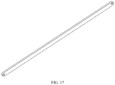
- Both ends of the stabilizing support beam 7 are connected to the carrying-frame fourth connection trunnions 27 of the two lateral carrying frames 2, correspondingly, to improve the stability of the test bench, as shown in FIG. 17 .
- the present invention proposes the similarity simulation test device for solid-liquid coupling of coal and rock mass.
- the sealing back plate 11, the lateral sealing plate 12, the sealing bottom plate 14, and the laid coal and rock mass materials together form the box-shaped sealing space.
- the control over water pressure can be achieved by the first loading mechanism 3 and the hydraulic jack 6.
- the second vertical loading mechanism 4 can realize the vertical loading on the coal and rock mass materials.
- the third lateral loading mechanism 5 can realize the lateral loading on the coal and rock mass materials.
- the present invention also proposes a method for using the similarity simulation test device for solid-liquid coupling of coal and rock mass.
- the method includes:
Landscapes
- Chemical & Material Sciences (AREA)
- Physics & Mathematics (AREA)
- General Health & Medical Sciences (AREA)
- Life Sciences & Earth Sciences (AREA)
- Analytical Chemistry (AREA)
- Biochemistry (AREA)
- Health & Medical Sciences (AREA)
- General Physics & Mathematics (AREA)
- Immunology (AREA)
- Pathology (AREA)
- Fluid Mechanics (AREA)
- Dispersion Chemistry (AREA)
- Investigating Strength Of Materials By Application Of Mechanical Stress (AREA)
Abstract
Description
- The present invention relates to the field of coal and, more particularly, to a test device for conducting a similarity simulation test on solid-liquid coupling of coal and rock mass, and a method for using the test device.
- A similar material simulation test is a technical means to reproduce an engineering site in a laboratory based on geological conditions, force conditions and boundary conditions of the engineering site, using similarity theories such as geometric similarity, mechanical similarity and physical parameter similarity, and is widely used in mining engineering, civil engineering, geotechnical engineering and other engineering fields.
- At present, traditional similarity simulation tests mainly simulate mine pressure manifestation of coal and rock mass, and rarely can realize similarity simulation of solid-liquid coupling. Some scholars have carried out seepage experiments for small-scale coal or rock specimens. For example, invention patent
CN202110000142.8 CN201910567055.3 CN201910513853.8 CN201811416280.9 - As discussed above, it can be known that the existing solid-liquid coupling experiment devices cannot control water pressure or mine pressure changes, cannot achieve simulation of stress, seepage, damage, destroy and other changes of coal and rock layers under the combined action of mine pressure and water pressure on the coal and rock mass. There is no such similarity simulation test device at home and abroad.
- In view of the above problems, the present invention proposes a similarity simulation test device for solid-liquid coupling of coal and rock mass, and a method for using the similarity simulation test device. The similarity simulation test device can adjust water pressure and mine pressure to which the coal and rock mass is subjected, and realize similarity simulation test analysis of stress, seepage, damage and destroy of the coal and rock mass under the combined action of water pressure and mine pressure.
- A similarity simulation test device for solid-liquid coupling of coal and rock mass according to the present invention includes: a test body carrying frame, a lateral carrying frame, a first loading mechanism, a second vertical loading mechanism, a third lateral loading mechanism, a hydraulic jack, and a stabilizing support beam.
- The similarity simulation test device for solid-liquid coupling of the coal and rock mass consists of one test body carrying frame, two lateral carrying frames, one first loading mechanism, one second vertical loading mechanism, two third lateral loading mechanisms, two hydraulic jacks, and one stabilizing support beam. Both ends of the first loading mechanism are connected to respective first ends of the two hydraulic jacks, and respective second ends of the two hydraulic jacks are connected to the test body carrying frame. The lateral carrying frames are connected to the test body carrying frame, the second vertical loading mechanism, the third lateral loading mechanisms, and the stabilizing support beam. Both ends of the second vertical loading mechanism are connected to the two lateral carrying frames, correspondingly. The third lateral loading mechanisms are connected to the two lateral carrying frames. Both ends of the stabilizing support beam are connected to the two lateral carrying frames, correspondingly.
- Further, the test body carrying frame includes: a sealing back plate, a lateral sealing plate, a water baffle, a sealing bottom plate, a bearing bottom plate, a water channel, a water collection bin, a first water outlet pipe, a second water outlet pipe, a support leg, a first connection trunnion, a second connection trunnion, a third connection trunnion, and a fourth connection trunnion. The sealing back plate is fixedly connected to the lateral sealing plate and the sealing bottom plate. The bearing bottom plate is fixedly connected to the sealing bottom plate, and the bearing bottom plate is slightly lower than the sealing bottom plate to form a step. The bearing bottom plate has a water channel, and the water channel is adjacent to the water baffle. The water baffle is configured to stop seeping water from flowing out of a test bench and allow the seeping water to flow into the water collection bin through the water channel. The water collection bin is configured to collect water that seeps out of the coal and rock mass materials during a test. The first water outlet pipe is configured to monitor changes in water pressure and discharge the water at the end of the test. The second water outlet pipe is configured to discharge the water stored in the water collection bin. The first connection trunnion is connected to the first end of the hydraulic jack. The second connection trunnion, the third connection trunnion, and the fourth connection trunnion are connected to the lateral carrying frame, forming a stable test bench.
- Furthermore, the lateral carrying frame includes a carrying-frame support side plate, a carrying-frame guide hole, a carrying-frame threaded hole, a carrying-frame first connection trunnion, a carrying-frame second connection trunnion, a carrying-frame third connection trunnion, and a carrying-frame fourth connection trunnion. The carrying-frame first connection trunnion is connected to the second connection trunnion. The carrying-frame second connection trunnion is connected to the fourth connection trunnion. The carrying-frame third connection trunnion is connected to the third connection trunnion. The carrying-frame fourth connection trunnion is connected to one end of the stabilizing support beam.
- Furthermore, the first loading mechanism includes a first loading pressure plate, a first loading rib plate, a water injection pipe, and a first loading connection trunnion; and the first loading connection trunnion is connected to the second end of the hydraulic jack.
- Furthermore, the second vertical loading mechanism includes: a second loading pressure plate, a second loading fixing plate, a second loading guide pillar, a second loading bolt, a second loading connection trunnion. The second loading pressure plate is fixedly connected to the second loading guide pillar, the second loading fixing plate has a guide hole, and the second loading guide pillar is movable up and down along the guide hole. The second loading fixing plate has a threaded hole, and the second loading bolt applies a load to the second loading fixing plate through the threaded hole. The second loading connection trunnion is connected to the carrying-frame second connection trunnion.
- Furthermore, the third lateral loading mechanism includes a third lateral loading pressure plate, a third lateral loading guide pillar, and a third lateral loading bolt; the third lateral loading guide pillar is fixedly connected to the third lateral loading pressure plate; and the third lateral loading bolt applies a load to the third lateral loading pressure plate through the carrying-frame threaded hole.
- A method for using the similarity simulation test device for solid-liquid coupling of coal and rock mass includes:
- S001, determining physical and mechanical parameters of similar materials and geometrical parameters of a model based on actual conditions at an engineering site;
- S002, mounting a lateral carrying frame and a stabilizing support beam;
- S003, mounting a third lateral loading mechanism;
- S004, laying coal and rock mass materials;
- S005, mounting a second vertical loading mechanism;
- S006, adjusting vertical and lateral forces on the coal and rock mass;
- S007, mounting a first loading mechanism;
- S008, simulating an initial water pressure during a test;
- S009, conducting a solid-liquid coupling test on the coal and rock mass;
- S010, finishing the test and removing the similarity simulation test device.
-
-
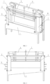
FIG. 1 is a structure diagram of a similarity simulation test device for solid-liquid coupling of a coal and rock mass according to an embodiment of the present invention; -
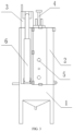
FIG. 2 is a front view of a similarity simulation test device for solid-liquid coupling of a coal and rock mass according to an embodiment of the present invention; -
FIG. 3 is a side view of a similarity simulation test device for solid-liquid coupling of a coal and rock mass according to an embodiment of the present invention; -
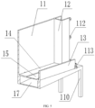
FIG. 4 is a structure diagram of a test body carrying frame according to an embodiment of the present invention; -
FIG. 5 is an A-A section view of a test body carrying frame according to an embodiment of the present invention; -
FIG. 6 is a top view of a test body carrying frame according to an embodiment of the present invention; -
FIG. 7 is a side view of a test body carrying frame according to an embodiment of the present invention; -
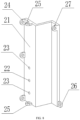
FIG. 8 is a structure diagram of a lateral carrying frame according to an embodiment of the present invention; -
FIG. 9 is a top view of a lateral carrying frame according to an embodiment of the present invention; -
FIG. 10 is a structure diagram of a first loading mechanism according to an embodiment of the present invention; -
FIG. 11 is a top view of a first loading mechanism according to an embodiment of the present invention; -
FIG. 12 is a structure diagram of a second vertical loading mechanism according to an embodiment of the present invention; -
FIG. 13 is a front view of a second vertical loading mechanism according to an embodiment of the present invention; -
FIG. 14 is a structure diagram of a third lateral loading mechanism according to an embodiment of the present invention; -
FIG. 15 is an assembly diagram of a third lateral loading mechanism and a test body carrying frame according to an embodiment of the present invention; -
FIG. 16 is a structure diagram of a hydraulic jack according to an embodiment of the present invention; -
FIG. 17 is a structure diagram of a stabilizing support beam according to an embodiment of the present invention; -
FIG. 18 is a flow diagram of a method for using a similarity simulation test device for solid-liquid coupling of a coal and rock mass according to an embodiment of the present invention. - The present application will be described in further detail below in conjunction with the accompanying drawings and specific embodiments. In the description of the present application, it should be noted that terms such as "central," "upper," "lower," "left," "right," "vertical," "horizontal," "inner" and "outer" should be construed to refer to the orientation as then described or as shown in the drawings under discussion. These terms are for convenience of description and do not indicate or imply that the device or element referred to must have a particular orientation or be constructed and operated in a particular orientation. Thus, these terms shall not be construed as limitation on the present invention.
- Referring to
FIGS. 1-3 , a similarity simulation test device for solid-liquid coupling of a coal and rock mass according to the present invention includes: a testbody carrying frame 1, alateral carrying frame 2, afirst loading mechanism 3, a secondvertical loading mechanism 4, a thirdlateral loading mechanism 5, ahydraulic jack 6, and a stabilizingsupport beam 7. - The similarity simulation test device for solid-liquid coupling of the coal and rock mass consists of one test
body carrying frame 1, two lateral carrying frames 2, onefirst loading mechanism 3, one secondvertical loading mechanism 4, two thirdlateral loading mechanisms 5, twohydraulic jacks 6, and one stabilizingsupport beam 7. - The
lateral carrying frames 2 are each connected to the testbody carrying frame 1, the secondvertical loading mechanism 4, the thirdlateral loading mechanisms 5, and the stabilizingsupport beam 7. Both ends of thefirst loading mechanism 3 are connected to respective first ends of the twohydraulic jacks 6, and respective second ends of the twohydraulic jacks 6 are connected to the testbody carrying frame 1. Both ends of the secondvertical loading mechanism 4 are connected to the two lateral carrying frames 2, correspondingly. The thirdlateral loading mechanisms 5 are connected to the two lateral carrying frames 2. Both ends of the stabilizingsupport beam 7 are connected to the two lateral carrying frames 2, correspondingly. Consequently, the stability of the test device is improved. - The test
body carrying frame 1 mainly includes: a sealing backplate 11, alateral sealing plate 12, awater baffle 13, a sealingbottom plate 14, a bearingbottom plate 15, awater channel 16, a water collection bin 17, a firstwater outlet pipe 18, a secondwater outlet pipe 19, asupport leg 110, afirst connection trunnion 111, asecond connection trunnion 112, athird connection trunnion 113, and afourth connection trunnion 114, as shown inFIGS. 4-7 . - The sealing back
plate 11 is fixedly connected to thelateral sealing plate 12 and the sealingbottom plate 14. The bearingbottom plate 15 is fixedly connected to the sealingbottom plate 14, and the bearingbottom plate 15 is slightly lower than the sealingbottom plate 14 to form a step. - Specifically, during a test, coal and rock mass materials are laid on the bearing
bottom plate 15, and a box-shaped sealing space is formed by the sealing backplate 11, thelateral sealing plate 12, the sealingbottom plate 14, and the laid coal and rock mass materials together. Water is injected into the sealing space. In such a way, a seepage effect of water on the coal and rock mass can be simulated. - In addition, the bearing
bottom plate 15 is slightly lower than the sealingbottom plate 14, allowing the coal and rock mass materials to make full contact with the sealingbottom plate 14, which is conducive to sealing and reduces water leakage due to poor sealing between the coal and rock mass materials and the bearingbottom plate 15. - The bearing
bottom plate 15 has awater channel 16, and the water channel is adjacent to thewater baffle 13. Thewater baffle 13 is mainly configured to stop seeping water from flowing out of a test bench and allow the seeping water to flow into the water collection bin 17 through thewater channel 16. - Specifically, the bearing
bottom plate 15 needs to be laid with the coal and rock mass materials according to actual project situations, to achieve similarity simulation tests on coal and rock mass materials of different widths. Thewater channel 16 is on a side adjacent to thewater baffle 13, which can increase an effective utilization area of the bearingbottom plate 15 and achieve similarity simulation tests on coal and rock mass materials of different widths. - The water collection bin 17 is configured to collect water that seeps out of the coal and rock mass materials during the test. Specifically, during the test, due to a seepage or splitting action of the water, as well as a damaging and destructive effect of the mine pressure on the coal and rock mass materials, the water passes through the coal and rock mass materials and flow into the collection water bin 17 through the
water channel 16. The damaging and destructive characteristics of the coal and rock mass materials can be analyzed by monitoring the water seepage amount as a function of time. - The first
water outlet pipe 18 is configured to monitor changes in water pressure and discharge the water at the end of the test. Specifically, by a water pressure gauge mounted on the firstwater outlet pipe 18, changes in water pressure within the box-shaped sealing space formed by the sealing backplate 11, thelateral sealing plate 12, the sealingbottom plate 14, and the laid coal and rock mass materials together can be monitored. Furthermore, after the test is completed, the water in the sealing space can be discharged through the firstwater outlet pipe 18. - The second
water outlet pipe 19 is configured to discharge the water stored in the water collection bin 17. Specifically, the water stored in the water collection bin 17 is discharged through the secondwater outlet pipe 19, allowing to monitor the water seepage amount as a function of time. - The
first connection trunnion 111 is connected to the first end of thehydraulic jack 6. Thesecond connection trunnion 112, thethird connection trunnion 113, and thefourth connection trunnion 114 are connected to thelateral carrying frame 2, forming a stable test bench. - The
lateral carrying frame 2 mainly includes a carrying-framesupport side plate 21, a carrying-frame guide hole 22, a carrying-frame threadedhole 23, a carrying-framefirst connection trunnion 24, a carrying-framesecond connection trunnion 25, a carrying-framethird connection trunnion 26, and a carrying-framefourth connection trunnion 27, as shown inFIGS. 8-9 . - The carrying-frame
first connection trunnion 24 is connected to thesecond connection trunnion 112. The carrying-framesecond connection trunnion 25 is connected to thefourth connection trunnion 114. The carrying-framethird connection trunnion 26 is connected to thethird connection trunnion 113. The carrying-framefourth connection trunnion 27 is connected to one end of the stabilizingsupport beam 7. - The
first loading mechanism 3 mainly includes a firstloading pressure plate 31, a firstloading rib plate 32, awater injection pipe 33, and a firstloading connection trunnion 34, as shown inFIGS. 10-11 . - The first
loading connection trunnion 34 is connected to the second end of thehydraulic jack 6. Specifically, the firstloading pressure plate 31 of thefirst loading mechanism 3 is within the box-shaped sealing space formed by the sealing backplate 11, thelateral sealing plate 12, the sealingbottom plate 14, and the laid coal and rock mass materials together. Two firstloading connection trunnions 34 are connected to respective first ends of the twohydraulic jacks 6. Water is injected into the sealing space through thewater injection pipe 33. By simultaneously retracting the twohydraulic jacks 6, pressure can be applied to the water in the sealing space through the firstloading pressure plate 31. The magnitude of the pressurizing load can be monitored by a pressure gauge mounted on the firstwater outlet pipe 18, enabling the simulation and adjustment of changes in the water pressure in the sealing space. - In addition, the first
loading rib plate 32 may be of an I-shaped structure, so that the stability of the mechanism can be improved when loads are applied at both ends. - The second
vertical loading mechanism 4 mainly includes: a secondloading pressure plate 41, a secondloading fixing plate 42, a secondloading guide pillar 43, asecond loading bolt 44, a secondloading connection trunnion 45, as shown inFIGS. 12-13 . - The second
loading pressure plate 41 is fixedly connected to the secondloading guide pillar 43. The secondloading fixing plate 42 has a guide hole, and the secondloading guide pillar 43 can move up and down along the guide hole. The secondloading fixing plate 42 has a threaded hole, and thesecond loading bolt 44 applies a load to the secondloading fixing plate 42 through the threaded hole. The secondloading connection trunnion 45 is connected to the carrying-framesecond connection trunnion 25. - Specifically, the coal and rock mass materials are laid on the bearing
bottom plate 15; the secondloading pressure plate 41 is arranged on the coal and rock mass materials; the secondloading fixing plate 42 is connected to the secondloading guide pillar 43 through the guide hole and is connected to the carrying-framesecond connection trunnion 25 by the secondloading connection trunnion 45. In such a case, pressure can be applied to the secondloading pressure plate 41 through thesecond loading bolt 44, and hence the load is applied to the coal and rock mass materials, realizing control over the magnitude of the load applied to the coal and rock mass materials. - Specifically, during a loading process, the second
loading guide pillar 43 can avoid movement of the secondloading pressure plate 41 in a wrong direction, ensuring that the load is applied in a vertical direction. Furthermore, since the secondloading connection trunnion 45 is connected to the carrying-framesecond connection trunnion 25, and the secondloading fixing plate 42 has the threaded hole, thesecond loading bolt 44 can control the magnitude of the load applied to the secondloading pressure plate 41 by the number of turns it is rotated, which can realize the small adjustment of the load value and achieve precise control over the applied load. - The third
lateral loading mechanism 5 mainly includes a third lateralloading pressure plate 51, a third lateral loadingguide pillar 52, and a thirdlateral loading bolt 53, as shown inFIG. 14 . - The third lateral loading
guide pillar 52 is fixedly connected to the third lateralloading pressure plate 51. The thirdlateral loading bolt 53 applies a load to the third lateralloading pressure plate 51 through the carrying-frame threadedhole 23. - Specifically, the third lateral
loading pressure plate 51 is on a side of thelateral carrying frame 2 close to the coal and rock mass, as shown inFIG. 15 . The third lateral loadingguide pillar 52 passes through the carrying-frame guide hole 22, and a movement direction of the third lateralloading pressure plate 51 is controlled by the third lateral loadingguide pillar 52. - In addition, the third
lateral loading bolt 53 applies a load to the third lateralloading pressure plate 51 through the carrying-frame threadedhole 23, to apply a lateral load to the coal and rock mass materials by the third lateralloading pressure plate 51. - One end of the
hydraulic jack 6 is connected to thefirst connection trunnion 111 and the other end of thehydraulic jack 6 is connected to the firstloading connection trunnion 34, to achieve control over the water pressure, as shown inFIG. 16 . - Both ends of the stabilizing
support beam 7 are connected to the carrying-framefourth connection trunnions 27 of the two lateral carrying frames 2, correspondingly, to improve the stability of the test bench, as shown inFIG. 17 . - The present invention proposes the similarity simulation test device for solid-liquid coupling of coal and rock mass. The sealing back
plate 11, thelateral sealing plate 12, the sealingbottom plate 14, and the laid coal and rock mass materials together form the box-shaped sealing space. The control over water pressure can be achieved by thefirst loading mechanism 3 and thehydraulic jack 6. The secondvertical loading mechanism 4 can realize the vertical loading on the coal and rock mass materials. The thirdlateral loading mechanism 5 can realize the lateral loading on the coal and rock mass materials. As a result, the requirements of similarity simulation tests for solid-liquid coupling of the coal and rock mass under different water pressure and different mine pressure conditions can be satisfied. - Referring to
FIG. 18 , the present invention also proposes a method for using the similarity simulation test device for solid-liquid coupling of coal and rock mass. The method includes: - S001, determining physical and mechanical parameters of similar materials and geometrical parameters of a model based on actual conditions at an engineering site;
- S002, mounting a
lateral carrying frame 2 and a stabilizingsupport beam 7, in which, specifically, thelateral carrying frame 2 is connected and fixed to a testbody carrying frame 1, and both ends of the stabilizingsupport beam 7 are connected and fixed to two lateral carrying frames 2 correspondingly; - S003, mounting a third
lateral loading mechanism 5, in which, specifically, a third lateral loadingguide pillar 52 of the thirdlateral loading mechanism 5 passes through a carrying-frame guide hole 22, and its position is limited by a thirdlateral loading bolt 53 through a carrying-frame threadedhole 23 according to a size requirement of the coal and rock mass; - S004, laying coal and rock mass materials, in which, specifically, the coal and rock mass materials are laid on a bearing
bottom plate 15 according to the geometrical parameters of the model and the physical and mechanical parameters of the model materials; - S005, mounting a second
vertical loading mechanism 4, in which, specifically, a secondloading pressure plate 41 is arranged on the coal and rock mass materials, a secondloading fixing plate 42 is connected to a secondloading guide pillar 43 through a guide hole and connected to a carrying-framesecond connection trunnion 25 through a secondloading connection trunnion 45, and at this time, pressure is exerted on the secondloading pressure plate 41 through asecond loading bolt 44 to simulate an initial force exerted on the coal and rock mass; - S006, adjusting vertical and lateral forces on the coal and rock mass, in which, specifically, a lateral load imposed by a third lateral
loading pressure plate 51 on the coal and rock mass can be adjusted by adjusting a thirdlateral loading bolt 53, and a vertical load imposed by the secondloading pressure plate 41 on the coal and rock mass can be adjusted by adjusting thesecond loading bolt 44; - S007, mounting a
first loading mechanism 3, in which, specifically, both ends of thefirst loading mechanism 3 are connected to respective first ends of twohydraulic jacks 6, and respective second ends of the twohydraulic jacks 6 are connected to the testbody carrying frame 1; - S008, simulating an initial water pressure during the test, in which, specifically, a water pressure gauge is mounted on a first
water outlet pipe 18 and seals the firstwater outlet pipe 18; water is injected through thewater injection pipe 33 according to a test requirement; during the water injection, a water level change can be determined by a pressure change of the water pressure gauge; and the water injection is stopped when an initial water pressure value is reached; - S009, conducting a solid-liquid coupling test on the coal and rock mass, in which, specifically, a value of the water pressure to which the coal and rock mass is subjected can be changed by adjusting an extension/retraction stroke of the
hydraulic jack 6; the vertical load imposed on the coal and rock mass materials can be changed by adjusting thesecond loading bolt 44; the lateral load imposed on the coal and rock mass materials can be changed by adjusting the thirdlateral loading bolt 53; the damage and destroy characteristics of the coal and rock mass materials can be analyzed by monitoring the water seepage amount collected by the water collection bin 17 as a function of time; and additionally, during the test, pressure sensors, displacement sensors and other relevant sensors can be added to monitor the damage and seepage characteristics of the coal and rock mass (the test system mainly provides the usage method of the test device, and users may adopt different monitoring means according to the test needs); - S010, finishing the test and removing the test device, in which, specifically, the water pressure gauge mounted on the first
water outlet pipe 18 is removed and the water is discharged; thefirst loading mechanism 3, thehydraulic jacks 6, the secondvertical loading mechanism 4 are removed; the coal and rock mass materials are then removed; the thirdlateral loading mechanism 5, the stabilizingsupport beam 7, and thelateral carrying frame 2 are removed. - The above description only involves principles and preferred embodiments of the present invention. It should be noted that other variations can be made by those skilled in the art based on the principles of the present invention and also fall into the protection scope of the present invention.
Claims (7)
- A similarity simulation test device for solid-liquid coupling of a coal and rock mass, comprising: a test body carrying frame (1), a lateral carrying frame (2), a first loading mechanism (3), a second vertical loading mechanism (4), a third lateral loading mechanism (5), a hydraulic jack (6), and a stabilizing support beam (7),
wherein:the similarity simulation test device for solid-liquid coupling of the coal and rock mass comprises one test body carrying frame (1), two lateral carrying frames (2), one first loading mechanism (3), one second vertical loading mechanism (4), two third lateral loading mechanisms (5), two hydraulic jacks (6), and one stabilizing support beam (7);both ends of the first loading mechanism (3) are connected to respective first ends of the two hydraulic jacks (6), and respective second ends of the two hydraulic jacks (6) are connected to the test body carrying frame (1);the lateral carrying frames (2) are connected to the test body carrying frame (1), the second vertical loading mechanism (4), the third lateral loading mechanisms (5), and the stabilizing support beam (7);both ends of the second vertical loading mechanism (4) are connected to the two lateral carrying frames (2), correspondingly;the third lateral loading mechanisms (5) are connected to the two lateral carrying frames (2); andboth ends of the stabilizing support beam (7) are connected to the two lateral carrying frames (2), correspondingly. - The similarity simulation test device according to claim 1, wherein:the test body carrying frame (1) comprises: a sealing back plate (11), a lateral sealing plate (12), a water baffle (13), a sealing bottom plate (14), a bearing bottom plate (15), a water channel (16), a water collection bin (17), a first water outlet pipe (18), a second water outlet pipe (19), a support leg (110), a first connection trunnion (111), a second connection trunnion (112), a third connection trunnion (113), and a fourth connection trunnion (114);the sealing back plate (11) is fixedly connected to the lateral sealing plate (12) and the sealing bottom plate (14);the bearing bottom plate (15) is fixedly connected to the sealing bottom plate (14), and the bearing bottom plate (15) is slightly lower than the sealing bottom plate (14) to form a step;the bearing bottom plate (15) has a water channel (16), and the water channel is adjacent to the water baffle (13);the water baffle (13) is configured to stop seeping water from flowing out of a test bench and allow the seeping water to flow into the water collection bin (17) through the water channel (16);the water collection bin (17) is configured to collect water that seeps out of the coal and rock mass materials during a test;the first water outlet pipe (18) is configured to monitor changes in water pressure and discharge the water at the end of the test;the second water outlet pipe (19) is configured to discharge the water stored in the water collection bin (17);the first connection trunnion (111) is connected to the first end of the hydraulic jack (6); andthe second connection trunnion (112), the third connection trunnion (113), and the fourth connection trunnion (114) are connected to the lateral carrying frame (2), forming a stable test bench.
- The similarity simulation test device according to claim 1 or 2, wherein:the lateral carrying frame (2) comprises a carrying-frame support side plate (21), a carrying-frame guide hole (22), a carrying-frame threaded hole (23), a carrying-frame first connection trunnion (24), a carrying-frame second connection trunnion (25), a carrying-frame third connection trunnion (26), and a carrying-frame fourth connection trunnion (27);the carrying-frame first connection trunnion (24) is connected to the second connection trunnion (112);the carrying-frame second connection trunnion (25) is connected to the fourth connection trunnion (114);the carrying-frame third connection trunnion (26) is connected to the third connection trunnion (113); andthe carrying-frame fourth connection trunnion (27) is connected to one end of the stabilizing support beam (7).
- The similarity simulation test device according to any one of claims 1 to 3, wherein:the first loading mechanism (3) comprises a first loading pressure plate (31), a first loading rib plate (32), a water injection pipe (33), and a first loading connection trunnion (34); andthe first loading connection trunnion (34) is connected to the second end of the hydraulic jack (6).
- The similarity simulation test device according to any one of claims 1 to 4, wherein:the second vertical loading mechanism (4) comprises: a second loading pressure plate (41), a second loading fixing plate (42), a second loading guide pillar (43), a second loading bolt (44), a second loading connection trunnion (45);the second loading pressure plate (41) is fixedly connected to the second loading guide pillar (43), the second loading fixing plate (42) has a guide hole, and the second loading guide pillar (43) is movable up and down along the guide hole;the second loading fixing plate (42) has a threaded hole, and the second loading bolt (44) applies a load to the second loading fixing plate (42) through the threaded hole; andthe second loading connection trunnion (45) is connected to the carrying-frame second connection trunnion (25).
- The similarity simulation test device according to any one of claims 1 to 5, wherein:the third lateral loading mechanism (5) comprises a third lateral loading pressure plate (51), a third lateral loading guide pillar (52), and a third lateral loading bolt (53);the third lateral loading guide pillar (52) is fixedly connected to the third lateral loading pressure plate (51); andthe third lateral loading bolt (53) applies a load to the third lateral loading pressure plate (51) through the carrying-frame threaded hole (23).
- A method for using the similarity simulation test device for solid-liquid coupling of coal and rock mass according to any one of claims 1 to 6, comprising:S001, determining physical and mechanical parameters of similar materials and geometrical parameters of a model based on actual conditions at an engineering site;S002, mounting a lateral carrying frame (2) and a stabilizing support beam (7);S003, mounting a third lateral loading mechanism (5);S004, laying coal and rock mass materials;S005, mounting a second vertical loading mechanism (4);S006, adjusting vertical and lateral forces on the coal and rock mass;S007, mounting a first loading mechanism (3);S008, simulating an initial water pressure during a test;S009, conducting a solid-liquid coupling test on the coal and rock mass;S010, finishing the test and removing the similarity simulation test device.
Applications Claiming Priority (1)
| Application Number | Priority Date | Filing Date | Title |
|---|---|---|---|
| CN202210000066.5A CN114235585B (en) | 2022-01-01 | 2022-01-01 | A coal-rock mass solid-liquid coupling similar simulation experiment device and application method |
Publications (2)
| Publication Number | Publication Date |
|---|---|
| EP4206646A1 true EP4206646A1 (en) | 2023-07-05 |
| EP4206646B1 EP4206646B1 (en) | 2025-03-12 |
Family
ID=80745572
Family Applications (1)
| Application Number | Title | Priority Date | Filing Date |
|---|---|---|---|
| EP22187729.3A Active EP4206646B1 (en) | 2022-01-01 | 2022-07-29 | Similarity simulation test device for solid-liquid coupling of coal and rock mass, and method for using the device |
Country Status (2)
| Country | Link |
|---|---|
| EP (1) | EP4206646B1 (en) |
| CN (1) | CN114235585B (en) |
Cited By (2)
| Publication number | Priority date | Publication date | Assignee | Title |
|---|---|---|---|---|
| CN117092012A (en) * | 2023-10-18 | 2023-11-21 | 华侨大学 | Tunnel excavation surrounding rock infiltration test device |
| CN118639702A (en) * | 2024-07-03 | 2024-09-13 | 中交第三航务工程局有限公司 | A device and method for rock-embedded pile pull-out test |
Families Citing this family (2)
| Publication number | Priority date | Publication date | Assignee | Title |
|---|---|---|---|---|
| CN115791415B (en) * | 2022-11-14 | 2025-07-25 | 扎赉诺尔煤业有限责任公司 | Stress loading experimental device based on coal seam mining face |
| CN116859028B (en) * | 2023-09-04 | 2023-11-24 | 徐州矿务集团有限公司 | Solid-liquid-gas coupling simulation device for protecting layer exploitation and experimental method |
Citations (2)
| Publication number | Priority date | Publication date | Assignee | Title |
|---|---|---|---|---|
| CN105891447A (en) * | 2016-05-05 | 2016-08-24 | 安徽理工大学 | Similarity test device and visualizing method for bearing fault mining activation and water bursting channel forming process |
| CN110346216A (en) * | 2019-06-20 | 2019-10-18 | 太原理工大学 | Three axis load testing machine of coal and rock and method in the case of a kind of simulation driving disturbance |
Family Cites Families (10)
| Publication number | Priority date | Publication date | Assignee | Title |
|---|---|---|---|---|
| JP2009236802A (en) * | 2008-03-28 | 2009-10-15 | Railway Technical Res Inst | Three-dimensional tunnel loading simulation device |
| CN105118365A (en) * | 2015-09-21 | 2015-12-02 | 安徽理工大学 | Similar simulation stereo experiment model of coal mining working face |
| CN106706883B (en) * | 2016-12-29 | 2019-06-25 | 华北科技学院 | Test device for fluid-structure interaction similarity simulation |
| CN206557184U (en) * | 2017-01-19 | 2017-10-13 | 华北科技学院 | The simulation box of three-dimensional solid-liquid coupling similarity simulation experiment |
| CN207379839U (en) * | 2017-11-21 | 2018-05-18 | 中国矿业大学(北京) | A kind of axis pressure, hydraulic pressure coupling similarity simulation experiment system |
| CN208188101U (en) * | 2018-03-23 | 2018-12-04 | 新疆维吾尔自治区煤炭科学研究所 | Coal mining solid-liquid coupling similarity simulation experiment system under artesian aquifer |
| CN109655494A (en) * | 2018-11-26 | 2019-04-19 | 中国矿业大学 | A kind of mining overburden solid-liquid coupling three dimensional lossless monitoring system and method |
| CN110208491A (en) * | 2019-06-14 | 2019-09-06 | 太原理工大学 | A kind of device and method of three-dimensional solid-liquid coupling analog simulation coal seam goaf ponding |
| CN112730809A (en) * | 2020-12-31 | 2021-04-30 | 安徽理工大学 | Fluid-solid coupling similar test device and test method for pressure-bearing underwater mining |
| CN112557280B (en) * | 2021-01-01 | 2022-08-19 | 天地科技股份有限公司 | Solid-liquid coupling experimental device and experimental method |
-
2022
- 2022-01-01 CN CN202210000066.5A patent/CN114235585B/en active Active
- 2022-07-29 EP EP22187729.3A patent/EP4206646B1/en active Active
Patent Citations (2)
| Publication number | Priority date | Publication date | Assignee | Title |
|---|---|---|---|---|
| CN105891447A (en) * | 2016-05-05 | 2016-08-24 | 安徽理工大学 | Similarity test device and visualizing method for bearing fault mining activation and water bursting channel forming process |
| CN110346216A (en) * | 2019-06-20 | 2019-10-18 | 太原理工大学 | Three axis load testing machine of coal and rock and method in the case of a kind of simulation driving disturbance |
Cited By (3)
| Publication number | Priority date | Publication date | Assignee | Title |
|---|---|---|---|---|
| CN117092012A (en) * | 2023-10-18 | 2023-11-21 | 华侨大学 | Tunnel excavation surrounding rock infiltration test device |
| CN117092012B (en) * | 2023-10-18 | 2023-12-19 | 华侨大学 | A kind of tunnel excavation surrounding rock seepage test device |
| CN118639702A (en) * | 2024-07-03 | 2024-09-13 | 中交第三航务工程局有限公司 | A device and method for rock-embedded pile pull-out test |
Also Published As
| Publication number | Publication date |
|---|---|
| EP4206646B1 (en) | 2025-03-12 |
| CN114235585A (en) | 2022-03-25 |
| CN114235585B (en) | 2023-07-18 |
Similar Documents
| Publication | Publication Date | Title |
|---|---|---|
| EP4206646B1 (en) | Similarity simulation test device for solid-liquid coupling of coal and rock mass, and method for using the device | |
| Indraratna et al. | Coupled discrete element–finite difference method for analysing the load-deformation behaviour of a single stone column in soft soil | |
| Han et al. | An analytical model for face stability of tunnels traversing the fault fracture zone with high hydraulic pressure | |
| Lee | Three-dimensional numerical analyses of the response of a single pile and pile groups to tunnelling in weak weathered rock | |
| CN111707805B (en) | Model test system for simulating excavation of tunnel rock-like pile body and operation method | |
| CN106198191B (en) | A kind of model test apparatus it is contemplated that the tunnel error resilience of Strike-slip fault is broken | |
| CN104897539B (en) | Suitable for the horizontal permeation instrument of soil body horizontal contact surface detrusion | |
| Ng et al. | Performance of existing piled raft and pile group due to adjacent multipropped excavation: 3D centrifuge and numerical modeling | |
| Borges et al. | Cylindrical excavations in clayey soils retained by jet grout walls: Numerical analysis and parametric study considering the influence of consolidation | |
| CN108061687A (en) | It is a kind of to study the geotechnical engineering analogue test platform for having Latent destruction face | |
| George et al. | Numerical investigation of soil arching in dense sand | |
| CN105651965B (en) | One kind can load analog simulation experimental rig and its application method | |
| CN211602719U (en) | Stope mine pressure three-dimensional physical simulation test platform of multi-functional top bottom plate gushing water | |
| CN108872297A (en) | Shield tail grouting slurry condensation and pipe piece floating process model test device | |
| Zidan et al. | Three dimensional numerical analysis of the effects of tunnelling near piled structures | |
| Zhu et al. | Coupled discrete element–finite difference method for analyzing subsidence control in fully mechanized solid backfilling mining | |
| Liu et al. | Pore pressure dynamics in early-age cemented fill under multiaxial stress conditions | |
| Zhang et al. | A unified numerical framework for the soil and fluid coupling problem considering mixture and separation | |
| CN113029800B (en) | A solid filling material compression test device and method | |
| CN211922746U (en) | An interface shear test system that can realize pile side grouting | |
| Li et al. | Upheaval buckling resistance of pipelines buried in unsaturated clay backfills | |
| CN214749449U (en) | Solid filling material compression test device | |
| CN205712214U (en) | Can the excavation models assay device of WATER LEVEL CHANGES in Simulation of Excavation Process | |
| CN105926685B (en) | Built-in retaining wall type soil pressure displacement effect test method | |
| Guo et al. | Analytical Method for the Buried Pipeline on an Elastic Foundation with Local Ground Subsidence |
Legal Events
| Date | Code | Title | Description |
|---|---|---|---|
| PUAI | Public reference made under article 153(3) epc to a published international application that has entered the european phase |
Free format text: ORIGINAL CODE: 0009012 |
|
| STAA | Information on the status of an ep patent application or granted ep patent |
Free format text: STATUS: THE APPLICATION HAS BEEN PUBLISHED |
|
| AK | Designated contracting states |
Kind code of ref document: A1 Designated state(s): AL AT BE BG CH CY CZ DE DK EE ES FI FR GB GR HR HU IE IS IT LI LT LU LV MC MK MT NL NO PL PT RO RS SE SI SK SM TR |
|
| STAA | Information on the status of an ep patent application or granted ep patent |
Free format text: STATUS: REQUEST FOR EXAMINATION WAS MADE |
|
| 17P | Request for examination filed |
Effective date: 20230727 |
|
| RBV | Designated contracting states (corrected) |
Designated state(s): AL AT BE BG CH CY CZ DE DK EE ES FI FR GB GR HR HU IE IS IT LI LT LU LV MC MK MT NL NO PL PT RO RS SE SI SK SM TR |
|
| GRAP | Despatch of communication of intention to grant a patent |
Free format text: ORIGINAL CODE: EPIDOSNIGR1 |
|
| STAA | Information on the status of an ep patent application or granted ep patent |
Free format text: STATUS: GRANT OF PATENT IS INTENDED |
|
| INTG | Intention to grant announced |
Effective date: 20241209 |
|
| RAP3 | Party data changed (applicant data changed or rights of an application transferred) |
Owner name: CHINA COAL RESEARCH INSTITUTE Owner name: CCTEG COAL MINING RESEARCH INSTITUTE Owner name: TIANDI SCIENCE & TECHNOLOGY CO.,LTD |
|
| GRAS | Grant fee paid |
Free format text: ORIGINAL CODE: EPIDOSNIGR3 |
|
| GRAA | (expected) grant |
Free format text: ORIGINAL CODE: 0009210 |
|
| STAA | Information on the status of an ep patent application or granted ep patent |
Free format text: STATUS: THE PATENT HAS BEEN GRANTED |
|
| AK | Designated contracting states |
Kind code of ref document: B1 Designated state(s): AL AT BE BG CH CY CZ DE DK EE ES FI FR GB GR HR HU IE IS IT LI LT LU LV MC MK MT NL NO PL PT RO RS SE SI SK SM TR |
|
| REG | Reference to a national code |
Ref country code: GB Ref legal event code: FG4D |
|
| REG | Reference to a national code |
Ref country code: CH Ref legal event code: EP |
|
| REG | Reference to a national code |
Ref country code: DE Ref legal event code: R096 Ref document number: 602022011638 Country of ref document: DE |
|
| REG | Reference to a national code |
Ref country code: IE Ref legal event code: FG4D |
|
| PG25 | Lapsed in a contracting state [announced via postgrant information from national office to epo] |
Ref country code: RS Free format text: LAPSE BECAUSE OF FAILURE TO SUBMIT A TRANSLATION OF THE DESCRIPTION OR TO PAY THE FEE WITHIN THE PRESCRIBED TIME-LIMIT Effective date: 20250612 |
|
| PG25 | Lapsed in a contracting state [announced via postgrant information from national office to epo] |
Ref country code: FI Free format text: LAPSE BECAUSE OF FAILURE TO SUBMIT A TRANSLATION OF THE DESCRIPTION OR TO PAY THE FEE WITHIN THE PRESCRIBED TIME-LIMIT Effective date: 20250312 |
|
| PG25 | Lapsed in a contracting state [announced via postgrant information from national office to epo] |
Ref country code: ES Free format text: LAPSE BECAUSE OF FAILURE TO SUBMIT A TRANSLATION OF THE DESCRIPTION OR TO PAY THE FEE WITHIN THE PRESCRIBED TIME-LIMIT Effective date: 20250312 |
|
| REG | Reference to a national code |
Ref country code: LT Ref legal event code: MG9D |
|
| PG25 | Lapsed in a contracting state [announced via postgrant information from national office to epo] |
Ref country code: NO Free format text: LAPSE BECAUSE OF FAILURE TO SUBMIT A TRANSLATION OF THE DESCRIPTION OR TO PAY THE FEE WITHIN THE PRESCRIBED TIME-LIMIT Effective date: 20250612 |
|
| PG25 | Lapsed in a contracting state [announced via postgrant information from national office to epo] |
Ref country code: HR Free format text: LAPSE BECAUSE OF FAILURE TO SUBMIT A TRANSLATION OF THE DESCRIPTION OR TO PAY THE FEE WITHIN THE PRESCRIBED TIME-LIMIT Effective date: 20250312 |
|
| REG | Reference to a national code |
Ref country code: NL Ref legal event code: MP Effective date: 20250312 |
|
| PG25 | Lapsed in a contracting state [announced via postgrant information from national office to epo] |
Ref country code: LV Free format text: LAPSE BECAUSE OF FAILURE TO SUBMIT A TRANSLATION OF THE DESCRIPTION OR TO PAY THE FEE WITHIN THE PRESCRIBED TIME-LIMIT Effective date: 20250312 |
|
| PGFP | Annual fee paid to national office [announced via postgrant information from national office to epo] |
Ref country code: FR Payment date: 20250623 Year of fee payment: 4 |
|
| PG25 | Lapsed in a contracting state [announced via postgrant information from national office to epo] |
Ref country code: BG Free format text: LAPSE BECAUSE OF FAILURE TO SUBMIT A TRANSLATION OF THE DESCRIPTION OR TO PAY THE FEE WITHIN THE PRESCRIBED TIME-LIMIT Effective date: 20250312 Ref country code: GR Free format text: LAPSE BECAUSE OF FAILURE TO SUBMIT A TRANSLATION OF THE DESCRIPTION OR TO PAY THE FEE WITHIN THE PRESCRIBED TIME-LIMIT Effective date: 20250613 |
|
| REG | Reference to a national code |
Ref country code: AT Ref legal event code: MK05 Ref document number: 1775362 Country of ref document: AT Kind code of ref document: T Effective date: 20250312 |
|
| PG25 | Lapsed in a contracting state [announced via postgrant information from national office to epo] |
Ref country code: NL Free format text: LAPSE BECAUSE OF FAILURE TO SUBMIT A TRANSLATION OF THE DESCRIPTION OR TO PAY THE FEE WITHIN THE PRESCRIBED TIME-LIMIT Effective date: 20250312 |
|
| PG25 | Lapsed in a contracting state [announced via postgrant information from national office to epo] |
Ref country code: SE Free format text: LAPSE BECAUSE OF FAILURE TO SUBMIT A TRANSLATION OF THE DESCRIPTION OR TO PAY THE FEE WITHIN THE PRESCRIBED TIME-LIMIT Effective date: 20250312 |
|
| PG25 | Lapsed in a contracting state [announced via postgrant information from national office to epo] |
Ref country code: SM Free format text: LAPSE BECAUSE OF FAILURE TO SUBMIT A TRANSLATION OF THE DESCRIPTION OR TO PAY THE FEE WITHIN THE PRESCRIBED TIME-LIMIT Effective date: 20250312 |
|
| PG25 | Lapsed in a contracting state [announced via postgrant information from national office to epo] |
Ref country code: PT Free format text: LAPSE BECAUSE OF FAILURE TO SUBMIT A TRANSLATION OF THE DESCRIPTION OR TO PAY THE FEE WITHIN THE PRESCRIBED TIME-LIMIT Effective date: 20250714 |
|
| PGFP | Annual fee paid to national office [announced via postgrant information from national office to epo] |
Ref country code: DE Payment date: 20250618 Year of fee payment: 4 |
|
| PG25 | Lapsed in a contracting state [announced via postgrant information from national office to epo] |
Ref country code: IT Free format text: LAPSE BECAUSE OF FAILURE TO SUBMIT A TRANSLATION OF THE DESCRIPTION OR TO PAY THE FEE WITHIN THE PRESCRIBED TIME-LIMIT Effective date: 20250312 Ref country code: PL Free format text: LAPSE BECAUSE OF FAILURE TO SUBMIT A TRANSLATION OF THE DESCRIPTION OR TO PAY THE FEE WITHIN THE PRESCRIBED TIME-LIMIT Effective date: 20250312 |
|
| PG25 | Lapsed in a contracting state [announced via postgrant information from national office to epo] |
Ref country code: AT Free format text: LAPSE BECAUSE OF FAILURE TO SUBMIT A TRANSLATION OF THE DESCRIPTION OR TO PAY THE FEE WITHIN THE PRESCRIBED TIME-LIMIT Effective date: 20250312 |
|
| PG25 | Lapsed in a contracting state [announced via postgrant information from national office to epo] |
Ref country code: EE Free format text: LAPSE BECAUSE OF FAILURE TO SUBMIT A TRANSLATION OF THE DESCRIPTION OR TO PAY THE FEE WITHIN THE PRESCRIBED TIME-LIMIT Effective date: 20250312 Ref country code: CZ Free format text: LAPSE BECAUSE OF FAILURE TO SUBMIT A TRANSLATION OF THE DESCRIPTION OR TO PAY THE FEE WITHIN THE PRESCRIBED TIME-LIMIT Effective date: 20250312 |
|
| PG25 | Lapsed in a contracting state [announced via postgrant information from national office to epo] |
Ref country code: RO Free format text: LAPSE BECAUSE OF FAILURE TO SUBMIT A TRANSLATION OF THE DESCRIPTION OR TO PAY THE FEE WITHIN THE PRESCRIBED TIME-LIMIT Effective date: 20250312 |
|
| PG25 | Lapsed in a contracting state [announced via postgrant information from national office to epo] |
Ref country code: SK Free format text: LAPSE BECAUSE OF FAILURE TO SUBMIT A TRANSLATION OF THE DESCRIPTION OR TO PAY THE FEE WITHIN THE PRESCRIBED TIME-LIMIT Effective date: 20250312 |
|
| PG25 | Lapsed in a contracting state [announced via postgrant information from national office to epo] |
Ref country code: IS Free format text: LAPSE BECAUSE OF FAILURE TO SUBMIT A TRANSLATION OF THE DESCRIPTION OR TO PAY THE FEE WITHIN THE PRESCRIBED TIME-LIMIT Effective date: 20250712 |
|
| REG | Reference to a national code |
Ref country code: DE Ref legal event code: R097 Ref document number: 602022011638 Country of ref document: DE |
|
| PG25 | Lapsed in a contracting state [announced via postgrant information from national office to epo] |
Ref country code: DK Free format text: LAPSE BECAUSE OF FAILURE TO SUBMIT A TRANSLATION OF THE DESCRIPTION OR TO PAY THE FEE WITHIN THE PRESCRIBED TIME-LIMIT Effective date: 20250312 |
|
| PLBE | No opposition filed within time limit |
Free format text: ORIGINAL CODE: 0009261 |
|
| STAA | Information on the status of an ep patent application or granted ep patent |
Free format text: STATUS: NO OPPOSITION FILED WITHIN TIME LIMIT |
|
| REG | Reference to a national code |
Ref country code: CH Ref legal event code: L10 Free format text: ST27 STATUS EVENT CODE: U-0-0-L10-L00 (AS PROVIDED BY THE NATIONAL OFFICE) Effective date: 20260121 |
|
| 26N | No opposition filed |
Effective date: 20251215 |
|
| REG | Reference to a national code |
Ref country code: CH Ref legal event code: H13 Free format text: ST27 STATUS EVENT CODE: U-0-0-H10-H13 (AS PROVIDED BY THE NATIONAL OFFICE) Effective date: 20260224 |
|
| PG25 | Lapsed in a contracting state [announced via postgrant information from national office to epo] |
Ref country code: LU Free format text: LAPSE BECAUSE OF NON-PAYMENT OF DUE FEES Effective date: 20250729 |
|
| REG | Reference to a national code |
Ref country code: BE Ref legal event code: MM Effective date: 20250731 |
|
| PG25 | Lapsed in a contracting state [announced via postgrant information from national office to epo] |
Ref country code: BE Free format text: LAPSE BECAUSE OF NON-PAYMENT OF DUE FEES Effective date: 20250731 |
|
| PG25 | Lapsed in a contracting state [announced via postgrant information from national office to epo] |
Ref country code: CH Free format text: LAPSE BECAUSE OF NON-PAYMENT OF DUE FEES Effective date: 20250731 |
|
| PG25 | Lapsed in a contracting state [announced via postgrant information from national office to epo] |
Ref country code: LT Free format text: LAPSE BECAUSE OF FAILURE TO SUBMIT A TRANSLATION OF THE DESCRIPTION OR TO PAY THE FEE WITHIN THE PRESCRIBED TIME-LIMIT Effective date: 20250312 |
|
| PG25 | Lapsed in a contracting state [announced via postgrant information from national office to epo] |
Ref country code: IE Free format text: LAPSE BECAUSE OF NON-PAYMENT OF DUE FEES Effective date: 20250729 |
|
| PG25 | Lapsed in a contracting state [announced via postgrant information from national office to epo] |
Ref country code: MC Free format text: LAPSE BECAUSE OF FAILURE TO SUBMIT A TRANSLATION OF THE DESCRIPTION OR TO PAY THE FEE WITHIN THE PRESCRIBED TIME-LIMIT Effective date: 20250312 |
|
| PG25 | Lapsed in a contracting state [announced via postgrant information from national office to epo] |
Ref country code: CY Free format text: LAPSE BECAUSE OF FAILURE TO SUBMIT A TRANSLATION OF THE DESCRIPTION OR TO PAY THE FEE WITHIN THE PRESCRIBED TIME-LIMIT Effective date: 20250312 |