EP4206601B1 - Dispositif d'echange thermique et materiel comprenant le dispositif d'echange thermique - Google Patents
Dispositif d'echange thermique et materiel comprenant le dispositif d'echange thermique Download PDFInfo
- Publication number
- EP4206601B1 EP4206601B1 EP22216806.4A EP22216806A EP4206601B1 EP 4206601 B1 EP4206601 B1 EP 4206601B1 EP 22216806 A EP22216806 A EP 22216806A EP 4206601 B1 EP4206601 B1 EP 4206601B1
- Authority
- EP
- European Patent Office
- Prior art keywords
- fluid
- heat exchange
- exchange device
- tubes
- heat
- Prior art date
- Legal status (The legal status is an assumption and is not a legal conclusion. Google has not performed a legal analysis and makes no representation as to the accuracy of the status listed.)
- Active
Links
Images


Classifications
-
- F—MECHANICAL ENGINEERING; LIGHTING; HEATING; WEAPONS; BLASTING
- F25—REFRIGERATION OR COOLING; COMBINED HEATING AND REFRIGERATION SYSTEMS; HEAT PUMP SYSTEMS; MANUFACTURE OR STORAGE OF ICE; LIQUEFACTION SOLIDIFICATION OF GASES
- F25B—REFRIGERATION MACHINES, PLANTS OR SYSTEMS; COMBINED HEATING AND REFRIGERATION SYSTEMS; HEAT PUMP SYSTEMS
- F25B23/00—Machines, plants or systems, with a single mode of operation not covered by groups F25B1/00 - F25B21/00, e.g. using selective radiation effect
- F25B23/006—Machines, plants or systems, with a single mode of operation not covered by groups F25B1/00 - F25B21/00, e.g. using selective radiation effect boiling cooling systems
-
- B—PERFORMING OPERATIONS; TRANSPORTING
- B64—AIRCRAFT; AVIATION; COSMONAUTICS
- B64G—COSMONAUTICS; VEHICLES OR EQUIPMENT THEREFOR
- B64G1/00—Cosmonautic vehicles
- B64G1/22—Parts of, or equipment specially adapted for fitting in or to, cosmonautic vehicles
- B64G1/46—Arrangements or adaptations of devices for control of environment or living conditions
- B64G1/50—Arrangements or adaptations of devices for control of environment or living conditions for temperature control
-
- F—MECHANICAL ENGINEERING; LIGHTING; HEATING; WEAPONS; BLASTING
- F28—HEAT EXCHANGE IN GENERAL
- F28F—DETAILS OF HEAT-EXCHANGE AND HEAT-TRANSFER APPARATUS, OF GENERAL APPLICATION
- F28F3/00—Plate-like or laminated elements; Assemblies of plate-like or laminated elements
- F28F3/12—Elements constructed in the shape of a hollow panel, e.g. with channels
-
- H—ELECTRICITY
- H01—ELECTRIC ELEMENTS
- H01Q—ANTENNAS, i.e. RADIO AERIALS
- H01Q1/00—Details of, or arrangements associated with, antennas
- H01Q1/02—Arrangements for de-icing; Arrangements for drying-out ; Arrangements for cooling; Arrangements for preventing corrosion
-
- H—ELECTRICITY
- H10—SEMICONDUCTOR DEVICES; ELECTRIC SOLID-STATE DEVICES NOT OTHERWISE PROVIDED FOR
- H10W—GENERIC PACKAGES, INTERCONNECTIONS, CONNECTORS OR OTHER CONSTRUCTIONAL DETAILS OF DEVICES COVERED BY CLASS H10
- H10W40/00—Arrangements for thermal protection or thermal control
- H10W40/10—Arrangements for heating
-
- H—ELECTRICITY
- H10—SEMICONDUCTOR DEVICES; ELECTRIC SOLID-STATE DEVICES NOT OTHERWISE PROVIDED FOR
- H10W—GENERIC PACKAGES, INTERCONNECTIONS, CONNECTORS OR OTHER CONSTRUCTIONAL DETAILS OF DEVICES COVERED BY CLASS H10
- H10W40/00—Arrangements for thermal protection or thermal control
- H10W40/40—Arrangements for thermal protection or thermal control involving heat exchange by flowing fluids
- H10W40/47—Arrangements for thermal protection or thermal control involving heat exchange by flowing fluids by flowing liquids, e.g. forced water cooling
-
- B—PERFORMING OPERATIONS; TRANSPORTING
- B64—AIRCRAFT; AVIATION; COSMONAUTICS
- B64G—COSMONAUTICS; VEHICLES OR EQUIPMENT THEREFOR
- B64G1/00—Cosmonautic vehicles
- B64G1/22—Parts of, or equipment specially adapted for fitting in or to, cosmonautic vehicles
- B64G1/66—Arrangements or adaptations of apparatus or instruments, not otherwise provided for
-
- F—MECHANICAL ENGINEERING; LIGHTING; HEATING; WEAPONS; BLASTING
- F28—HEAT EXCHANGE IN GENERAL
- F28D—HEAT-EXCHANGE APPARATUS, NOT PROVIDED FOR IN ANOTHER SUBCLASS, IN WHICH THE HEAT-EXCHANGE MEDIA DO NOT COME INTO DIRECT CONTACT
- F28D15/00—Heat-exchange apparatus with the intermediate heat-transfer medium in closed tubes passing into or through the conduit walls ; Heat-exchange apparatus employing intermediate heat-transfer medium or bodies
- F28D15/02—Heat-exchange apparatus with the intermediate heat-transfer medium in closed tubes passing into or through the conduit walls ; Heat-exchange apparatus employing intermediate heat-transfer medium or bodies in which the medium condenses and evaporates, e.g. heat pipes
- F28D15/0266—Heat-exchange apparatus with the intermediate heat-transfer medium in closed tubes passing into or through the conduit walls ; Heat-exchange apparatus employing intermediate heat-transfer medium or bodies in which the medium condenses and evaporates, e.g. heat pipes with separate evaporating and condensing chambers connected by at least one conduit; Loop-type heat pipes; with multiple or common evaporating or condensing chambers
-
- F—MECHANICAL ENGINEERING; LIGHTING; HEATING; WEAPONS; BLASTING
- F28—HEAT EXCHANGE IN GENERAL
- F28D—HEAT-EXCHANGE APPARATUS, NOT PROVIDED FOR IN ANOTHER SUBCLASS, IN WHICH THE HEAT-EXCHANGE MEDIA DO NOT COME INTO DIRECT CONTACT
- F28D21/00—Heat-exchange apparatus not covered by any of the groups F28D1/00 - F28D20/00
- F28D2021/0019—Other heat exchangers for particular applications; Heat exchange systems not otherwise provided for
- F28D2021/0021—Other heat exchangers for particular applications; Heat exchange systems not otherwise provided for for aircrafts or cosmonautics
-
- F—MECHANICAL ENGINEERING; LIGHTING; HEATING; WEAPONS; BLASTING
- F28—HEAT EXCHANGE IN GENERAL
- F28D—HEAT-EXCHANGE APPARATUS, NOT PROVIDED FOR IN ANOTHER SUBCLASS, IN WHICH THE HEAT-EXCHANGE MEDIA DO NOT COME INTO DIRECT CONTACT
- F28D21/00—Heat-exchange apparatus not covered by any of the groups F28D1/00 - F28D20/00
- F28D2021/0019—Other heat exchangers for particular applications; Heat exchange systems not otherwise provided for
- F28D2021/0028—Other heat exchangers for particular applications; Heat exchange systems not otherwise provided for for cooling heat generating elements, e.g. for cooling electronic components or electric devices
- F28D2021/0029—Heat sinks
-
- F—MECHANICAL ENGINEERING; LIGHTING; HEATING; WEAPONS; BLASTING
- F28—HEAT EXCHANGE IN GENERAL
- F28D—HEAT-EXCHANGE APPARATUS, NOT PROVIDED FOR IN ANOTHER SUBCLASS, IN WHICH THE HEAT-EXCHANGE MEDIA DO NOT COME INTO DIRECT CONTACT
- F28D21/00—Heat-exchange apparatus not covered by any of the groups F28D1/00 - F28D20/00
- F28D2021/0019—Other heat exchangers for particular applications; Heat exchange systems not otherwise provided for
- F28D2021/0068—Other heat exchangers for particular applications; Heat exchange systems not otherwise provided for for refrigerant cycles
- F28D2021/0071—Evaporators
-
- H—ELECTRICITY
- H01—ELECTRIC ELEMENTS
- H01Q—ANTENNAS, i.e. RADIO AERIALS
- H01Q1/00—Details of, or arrangements associated with, antennas
- H01Q1/27—Adaptation for use in or on movable bodies
- H01Q1/28—Adaptation for use in or on aircraft, missiles, satellites, or balloons
- H01Q1/288—Satellite antennas
Definitions
- This invention relates to heat exchange devices, and in particular, to heat exchange devices comprising heat exchangers.
- the invention also relates to equipment comprising several dissipative devices and a heat exchange device for maintaining them within a given temperature range.
- Dissipative equipment for space applications such as satellite radiating antennas, or amplifiers for amplifying signals emitted or received by radiating elements, require the use of heat exchangers to recover the heat dissipated by the equipment and control its temperature.
- heat exchangers include a fluid circulating near the equipment and recovering the dissipated heat.
- the heat exchange coefficient is low.
- a two-phase state of the fluid ensures a high heat exchange coefficient between the fluid and the dissipative equipment.
- some exchangers require the use of heaters at the inlet of the heat exchangers to ensure a two-phase flow from the inlet of the heat exchanger.
- some exchangers require oversizing the thermal control to take into account a loss of performance linked to a liquid flow at the start of the exchanger. Furthermore, in order to ensure the homogeneity of the characteristics of the radiating elements, it is important to have thermal homogeneity of the radiating elements.
- US7342787B1 discloses an apparatus for cooling a computer component, comprising a vapor compression system, comprising an evaporator coupled to the computer component; a condenser coupled to the evaporator; a compressor coupled to the evaporator and the condenser; and a thermoelectric module (TEM) comprising a hot side and a cold side; the cold side of the TEM being connected to the condenser; and the cold side of the TEM being operable to absorb heat from the condenser.
- TEM thermoelectric module
- US 2021/341185 A1 discloses a two-phase flow boiling cooling system, characterized in that a closed hydraulic circuit apparatus of a heat transfer refrigerant is provided, comprising: - means for pumping a refrigerant which, at least in some segments of the circuit, is two-phase liquid-vapor or multi-phase, - a heat sink-evaporator configured to transfer heat by conduction from a component to be cooled to the refrigerant, - a condenser, capable of condensing the vapor that develops on the evaporator while simultaneously dissipating the heat provided by the refrigerant both by conduction, convection and radiation and by condensation into the environment, - a reservoir that also serves as an expansion tank, or a reservoir and an expansion tank that are separate and connected to each other, - a plurality of sensors, including flow, pressure and temperature sensors and an electronic pump control system.
- a closed hydraulic circuit apparatus of a heat transfer refrigerant comprising: - means for pumping a ref
- US 5960866 discloses a cooling unit for electronic devices, the manufacturing method comprising the steps of: (a) preparing a plate-like metal block for removing heat generated by an electronic component, the metal block having holes in the thick portion of the metal block and having convex portions formed on one or both major surfaces of the metal block; (b) inserting heat pipes into the holes; and (c) applying a local, two-dimensional force from the surface of the metal block to the convex portions to make the surface flat, bringing the outer surface of each heat pipe into close contact with the inner wall of each hole in the metal block.
- the invention proposes a system making it possible to guarantee at least one channel having a two-phase flow near dissipative equipment and ensuring a high heat exchange coefficient without needing a heater at the inlet of a heat exchanger and without needing to oversize the associated thermal control.
- the invention relates to a heat exchange device comprising a heat exchanger having a flow comprising several channels in which a fluid flows in opposite directions and the fluid is in a two-phase state in at least one of the channels.
- the invention improves the situation by proposing a heat exchange device comprising a thermal loop in which a fluid circulates, the thermal loop comprising: a heat exchanger comprising at least two metal tubes arranged in parallel, the fluid circulating in a first direction in one of the two tubes and in a second direction opposite to the first direction in the other tube; a metal base on which the two tubes are fixed; a pump configured to circulate the fluid in the two metal tubes with a flow rate; a condenser for removing heat from the fluid, where fluid flow conditions are adapted to allow the fluid to be in a two-phase state in one of the two tubes, the flow conditions including the flow rate of the fluid and a size of the tubes; and a heater configured to transfer thermal energy from a channel connecting an outlet of the exchanger to an inlet of the condenser to a channel connecting an outlet of the pump to an inlet of the exchanger.
- the at least two metal tubes are connected in series.
- the at least two metal tubes are connected in parallel.
- the heat exchange device comprises a first temperature sensor configured to measure a first temperature of the fluid circulating between the pump and the heat exchanger.
- the heat exchange device includes a second temperature sensor configured to measure a second temperature of the fluid circulating between the heat exchanger and the condenser.
- the fluid circulates in a liquid state in the pump.
- the fluid is ammonia.
- the invention improves the situation by proposing equipment comprising a heat exchange device according to one of the preceding claims and several dissipative devices arranged on the metal base, the dissipative devices being aligned with the at least two metal tubes so that each dissipative device exchanges heat with the fluid circulating in each of the at least two metal tubes.
- the heat exchange device 100 comprises a thermal loop 106 in which a heat transfer fluid circulates.
- the fluid may be, for example, based on ammonia, pentafluoropropane or tetrafluoroethane (Freon type, products sold by the company DuPont de Nemours).
- the thermal loop 106 comprises a heat exchanger 108 comprising two metal tubes 102a, 102b arranged in parallel, the fluid circulating in a first direction in one of the two tubes and in a second direction opposite to the first direction in the other tube.
- the two metal tubes 102a, 102b are connected in series.
- the heat exchanger 108 comprises a fluid inlet 120a at the metal tube 102a and a fluid outlet 120b at the metal tube 102b, the two tubes 102a, 102b being connected by a tube allowing the fluid to circulate from the metal tube 102a to the metal tube 102b.
- the thermal loop 106 also comprises a metal base plate 104 on which the two tubes 102a, 102b are fixed.
- the two tubes 102a and 102b can be fixed on an external face of the base plate 104, or even embedded in the base plate 104.
- Dissipative equipment can be fixed on the metal base plate 104, for example on the surface opposite the surface on which the two metal tubes 102a, 102b are fixed.
- the dissipative equipment may be radiating elements, for example used in a radiating antenna of a satellite, which dissipates heat recovered by the fluid circulating in the thermal loop 106.
- the dissipative equipment may also be amplifiers making it possible to amplify signals emitted and/or received by radiating elements.
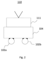
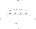
- THE figures 2 And 3 represent an electronic scanning antenna 110 equipped with a heat exchange device according to the invention.
- An electronic scanning antenna typically has numerous radiating elements 111.
- the radiating elements 111 are arranged on the sole 104, aligned parallel to the tubes 102a and 102b.
- the Figure 2 represents the antenna 110 in section perpendicular to the tubes 102a and 102b and the Figure 3 represents the antenna 110 in profile parallel to the tubes 102a and 102b.
- the correct operation of the antenna 110, both in transmission and in reception, depends on the temperature of each radiating element 111. More precisely, the electromagnetic characteristics of a radiating element can vary according to its temperature.
- each radiating element 111 can all be in a narrow temperature range.
- thermal homogeneity of the different radiating elements 111 is improved.
- the implementation of the invention can be carried out with other equipment and more generally all types of dissipative equipment for which it is sought to improve the thermal homogeneity.
- the thermal loop 106 also comprises a pump 114 configured to circulate the fluid in the two metal tubes 102a, 102b with a flow rate allowing the fluid to be in a two-phase state in one of the two tubes 102a, 102b.
- a pump 114 configured to circulate the fluid in the thermal loop 106, and the fluid circulating in the pump 114 is in the liquid state.
- a two-phase state of the fluid makes it possible to guarantee a high heat exchange coefficient between the fluid and the dissipative equipment. On the contrary, when the fluid is in the liquid state, the heat exchange coefficient is low.
- the thermal loop 106 of the present invention is configured so that, when the fluid circulates in the thermal loop 106 close to the dissipative equipment and recovers the emitted heat, the temperature of the fluid increases until it reaches its saturation temperature.
- Fluid flow conditions can therefore be adapted to have a two-phase state in at least one of the two metal tubes 102a, 102b in order to ensure a two-phase state of the fluid under the dissipative equipment 111 placed on the base 104.
- the flow rate of the pump 114, a dimension of the metal tubes 102a (a diameter and/or a length), 102b, a positioning of the equipment on the base 104 can be adapted in order to ensure a two-phase state of the fluid under the dissipative equipment 111 (that is to say, in at least the entirety of the metal tube 102b).
- the thermal loop 106 comprises a condenser 116 for removing heat from the fluid.
- the fluid is in a two-phase state.
- the fluid circulates in a liquid state in the pump 114.
- the condenser 116 makes it possible to remove the heat received from the dissipative equipment 110 and to reduce the temperature of the fluid below its saturation temperature in order to return to the liquid state.
- the fluid can therefore be in a liquid state at an outlet of the condenser 116 in order to be in a liquid state while circulating in the pump 114.
- the condenser 116 can comprise one or more radiators making it possible to remove the heat from dissipative equipment placed on the metal baseplate 104 recovered by the fluid to the outside of the heat exchange device 100.
- two metal tubes 102a, 102b are shown.
- three or more metal tubes may be used, depending on the dissipative equipment placed on the metal sole 104 and the surface area of the metal sole 104.
- three metal tubes may be connected in series, with the fluid entering the heat exchanger 100 through an inlet of the first tube and exiting through an outlet of the third tube.
- FIG. 4 illustrates a portion of a heat exchange device 200 according to the invention.
- the pump 114, the condenser 116 and the heat exchanger may be those described above in connection with the Figure 1 .
- the two tubes of the heat exchanger 108 are connected in parallel.
- the heat exchanger 108 comprises a fluid inlet 220a separating into two connections allowing the fluid to flow towards the metal tube 102a and the level of the metal tube 102b, the fluid inlet at each metal tube 102a, 102b being opposite.
- the fluid outlet at each metal tube 102a, 102b being opposite and joining by connections to a common fluid outlet 220b.
- two metal tubes 102a, 102b are shown.
- three or more metal tubes may be used.
- the fluid inlet 220a may be separated into three or more connections allowing the fluid to flow to three or more metal tubes.
- the three or more metal tubes having a total length L, the fluid must be in a two-phase state at most when it reaches half the total length L of the tubes, in order to ensure a two-phase state of the fluid under the dissipative equipment 111 placed on the sole 104.
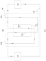
- FIG. 5 illustrates an example of a heat exchange device 300 according to the invention.
- the pump 114, the condenser 116 and the heat exchanger may be those described above in relation to the Figure 1 .
- the two metal tubes 102a, 102b are connected in series.
- the two metal tubes 102a, 102b may be connected in parallel.
- the heat exchange device 300 comprises a heater 130 configured to transfer thermal energy from a channel connecting an outlet 120b of the exchanger 108 to an inlet 126 of the condenser 116 to a channel connecting an outlet 124 of the pump 114 to an inlet 120a of the exchanger 108.
- the heater 130 makes it possible to increase the temperature of the fluid before entering the heat exchanger 108.
- the heater 130 may be used to ensure that the fluid is in a two-phase state in at least one of the two metal tubes 102a, 102b.
- the flow rate of the pump 114 and/or the arrangement of the equipment on the base 111 and/or the length of the metal tubes 102a, 102b can be adapted in order to ensure a two-phase state of the fluid under the dissipative equipment 111.
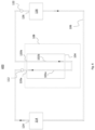
- FIG. 6 illustrates a portion of a heat exchange device 400 according to the invention.
- the pump 114, the condenser 116 and the heat exchanger may be those described above in connection with the Figure 1 .
- the two metal tubes 102a, 102b are connected in series.
- the two metal tubes 102a, 102b may be connected in parallel.
- the heat exchange device 400 comprises a first temperature sensor 112 configured to measure a first temperature of the fluid circulating between the pump 114 and the heat exchanger 108.
- the first sensor 112 is placed in the thermal loop 106, between the outlet 124 of the pump 114 and the inlet 120a of the heat exchanger 108.
- the first sensor 112 makes it possible to measure the temperature of the fluid before entering the heat exchanger 108, i.e. when the fluid is in the liquid state (the fluid being in the liquid state in the pump 114).
- the flow rate of the pump 114 can be adjusted to ensure that the fluid reaches the saturation temperature in at least one of the two metal tubes 102a, 102b.
- the heat exchange device 400 may comprise a second temperature sensor 122 configured to measure a second temperature of the fluid circulating between the heat exchanger 108 and the condenser 116.
- the second sensor 122 is placed in the thermal loop 106, between the outlet 120b of the heat exchanger 108 and the inlet 126 of the condenser 126.
- the condenser makes it possible to remove heat from the fluid in order to ensure that the fluid is in the liquid state in the pump 124.
- the second sensor 122 measures the temperature of the fluid in the two-phase state before entering the condenser 116.
- the flow rate of the pump can be adjusted in order to ensure that the fluid reaches a temperature below the saturation temperature at the outlet of the condenser.
- the sensors 112, 122 can be used to adapt the fluid flow conditions and ensure a two-phase state of the fluid under the dissipative equipment 111.
- the heat exchange device 400 comprises the first sensor 112 and the second sensor 122.
- the heat exchange device 400 may comprise only one of the two sensors.
- the two metal tubes are in series.
- the two metal tubes may be connected in parallel.
- the heat exchange device 400 may also comprise the heater 130 of the heat exchange device 300 of the Figure 5 .
- the heat exchanger 108 comprises two metal tubes 102a, 102b.
- the heat exchanger 108 may comprise three or more tubes.
- the tubes may be connected in series or in parallel.
- the electronic scanning antenna and more generally any equipment comprising several dissipative devices 111, shown in the figures 2 And 3 may include any of the examples of heat exchange devices described with reference to the other figures.
Landscapes
- Engineering & Computer Science (AREA)
- Physics & Mathematics (AREA)
- Thermal Sciences (AREA)
- Mechanical Engineering (AREA)
- General Engineering & Computer Science (AREA)
- Life Sciences & Earth Sciences (AREA)
- Health & Medical Sciences (AREA)
- Biodiversity & Conservation Biology (AREA)
- Environmental & Geological Engineering (AREA)
- Environmental Sciences (AREA)
- General Health & Medical Sciences (AREA)
- Toxicology (AREA)
- Remote Sensing (AREA)
- Aviation & Aerospace Engineering (AREA)
- Heat-Exchange Devices With Radiators And Conduit Assemblies (AREA)
Description
- Cette invention concerne des dispositifs d'échange thermique, et en particulier, des dispositifs d'échange thermique comprenant des échangeurs thermiques. L'invention concerne également un matériel comprenant plusieurs équipements dissipatifs et un dispositif d'échange thermique permettant de les maintenir dans une plage de température donnée.
- Les équipements dissipatifs pour les applications spatiales, tels que les antennes rayonnantes de satellite, ou les amplificateurs permettant d'amplifier des signaux émis ou reçu par des éléments rayonnants, nécessitent l'utilisation d'échangeurs thermiques permettant de récupérer la chaleur dissipée par les équipements et contrôler leur température. En particulier, les échangeurs thermiques comprennent un fluide circulant à proximité des équipements et récupérant la chaleur dissipée. Cependant, lorsque le fluide est à l'état liquide, le coefficient d'échange thermique est faible. Au contraire, un état diphasique du fluide permet de garantir un coefficient d'échange thermique élevé entre le fluide et les équipements dissipatifs. Ainsi, certains échangeurs nécessitent l'utilisation de réchauffeurs en entrée des échangeurs thermiques afin de garantir un écoulement diphasique dès l'entrée de l'échangeur thermique. Alternativement, certains échangeurs nécessitent un surdimensionnement du contrôle thermique afin de prendre en compte une perte de performance liée à un écoulement liquide en début d'échangeur. De plus, afin d'assurer l'homogénéité des caractéristiques des éléments rayonnants, il est important d'avoir une homogénéité thermique des éléments rayonnants.
US7342787B1 divulgue un appareil pour refroidir un composant informatique, comprenant un système de compression de vapeur, comprenant un évaporateur couplé au composant informatique ; un condenseur couplé à l'évaporateur ; un compresseur couplé à l'évaporateur et au condenseur ; et un module thermoélectrique (TEM) comprenant un côté chaud et un côté froid ; le côté froid du TEM étant connecté au condenseur ; et le côté froid du TEM pouvant fonctionner pour absorber la chaleur du condenseur.
US 2021/341185 A1 divulgue un système de refroidissement à deux phases à ébullition de flux, caractérisé en ce qu'un appareil à circuit hydraulique fermé d'un fluide frigorigène à transfert de chaleur est fourni, comprenant : - des moyens pour pomper un fluide frigorigène qui, au moins dans certains segments du circuit, est à deux phases liquide-vapeur ou multiphase, - un dissipateur de chaleur-évaporateur configuré pour transférer de la chaleur par conduction depuis un composant à refroidir vers le fluide frigorigène, - un condenseur, capable de condenser la vapeur qui se développe sur l'évaporateur tout en dissipant simultanément la chaleur fournie par le fluide frigorigène à la fois par conduction, convection et rayonnement et par condensation dans l'environnement, - un réservoir qui sert également de cuve d'expansion, ou un réservoir et une cuve d'expansion qui sont distincts et raccordés l'un à l'autre, - une pluralité de capteurs, comprenant des capteurs de débit, de pression et de température et un système de commande électronique de la pompe.
US 5960866 divulgue une unité de refroidissement pour dispositifs électroniques, le procédé de fabrication comprenant les étapes consistant à : (a) préparer un bloc métallique de type plaque pour éliminer la chaleur générée par un composant électronique, le bloc métallique comportant des trous dans la partie épaisse du un bloc métallique et ayant des parties convexes formées sur une surface principale ou sur les deux surfaces principales du bloc métallique ; (b) insérer des caloducs dans les trous ; et (c) appliquer une force locale et bidimensionnelle depuis la surface du bloc métallique sur les parties convexes pour rendre la surface plate, amenant la surface externe de chaque caloduc en contact étroit avec la paroi interne de chaque trou dans le bloc métallique. - Afin de pallier les inconvénients des dispositifs d'échange thermique, l'invention propose un système permettant de garantir au moins un canal ayant un écoulement diphasique à proximité d'équipements dissipatifs et assurant un coefficient d'échange thermique élevé sans avoir besoin d'un réchauffeur en entrée d'un échangeur thermique et sans avoir besoin de surdimensionner le contrôle thermique associé.
- A cet effet, l'invention a pour objet un dispositif d'échange thermique comprenant un échangeur thermique ayant un écoulement comprenant plusieurs canaux dans lesquels un fluide s'écoule en sens opposé et le fluide est à dans un état diphasique dans au moins un des canaux.
- L'invention vient à améliorer la situation en proposant un dispositif d'échange thermique comprenant une boucle thermique dans laquelle circule un fluide, la boucle thermique comprenant : un échangeur thermique comprenant au moins deux tubes métalliques disposés parallèlement, le fluide circulant dans un premier sens dans un des deux tubes et dans un deuxième sens opposé au premier sens dans l'autre tube ; une semelle métallique sur laquelle les deux tubes sont fixés ; une pompe configurée pour faire circuler le fluide dans les deux tubes métalliques avec un débit ; un condenseur pour évacuer de la chaleur du fluide, où des conditions d'écoulement du fluide sont adaptées pour permettre au fluide d'être dans un état diphasique dans un des deux tubes, les conditions d'écoulement comprenant le débit du fluide et une dimension des tubes ; et un réchauffeur configuré pour transférer de l'énergie thermique d'un canal reliant une sortie de l'échangeur à une entrée du condenseur vers un canal reliant une sortie de la pompe vers une entrée de l'échangeur.
- Dans un mode de réalisation, les aux moins deux tubes métalliques sont connectés en série.
- Dans un mode de réalisation, les aux moins deux tubes métalliques sont connectés en parallèle.
- Dans un mode de réalisation, le dispositif d'échange thermique comprend un premier capteur de température configuré pour mesurer une première température du fluide circulant entre la pompe et l'échangeur thermique.
- Dans un mode de réalisation, le dispositif d'échange thermique comprend un second capteur de température configuré pour mesurer une deuxième température du fluide circulant entre l'échangeur thermique et le condenseur.
- Dans un mode de réalisation, le fluide circule dans un état liquide dans la pompe.
- Dans un mode de réalisation, le fluide est de l'ammoniac.
- De plus, l'invention vient à améliorer la situation en proposant un matériel comprenant un dispositif d'échange thermique selon l'une des revendications précédentes et plusieurs équipements dissipatifs disposés sur la semelle métallique, les équipements dissipatifs étant alignés avec les au moins deux tubes métalliques de façon à ce que chaque équipements dissipatifs échange de la chaleur avec le fluide circulant dans chacun des au moins deux tubes métalliques.
- L'invention sera mieux comprise et d'autres avantages apparaîtront à la lecture de la description qui va suivre donnée à titre non limitatif et grâce aux figures parmi lesquelles :
- La
figure 1 illustre un exemple de dispositif d'échange thermique ; - Les
figures 2 et3 représentent un exemple d'antenne électronique à balayage équipée d'un dispositif d'échange thermique selon l'invention ; - La
figure 4 illustre un dispositif d'échange thermique non conforme à l'invention ; - La
figure 5 illustre un dispositif d'échange thermique selon l'invention ; et - La
figure 6 illustre un dispositif d'échange thermique non conforme à l'invention. - La
figure 1 illustre un exemple de dispositif d'échange thermique 100. Le dispositif d'échange thermique 100 comprend une boucle thermique 106 dans laquelle circule un fluide caloporteur. Le fluide peut être par exemple à base d'ammoniac, de pentafluoropropane ou tetrafluoroethane (type « fréon », produits vendus par la société DuPont de Nemours). La boucle thermique 106 comprend un échangeur thermique 108 comprenant deux tubes métalliques 102a, 102b disposés parallèlement, le fluide circulant dans un premier sens dans un des deux tubes et dans un deuxième sens opposé au premier sens dans l'autre tube. Dans cet exemple, les deux tubes métalliques 102a, 102b sont connectés en série. En particulier, l'échangeur thermique 108 comprend une entrée du fluide 120a au niveau du tube métallique 102a et une sortie du fluide 120b au niveau du tube métallique 102b, les deux tubes 102a, 102b étant connectés par un tube permettant au fluide de circuler du tube métallique 102a au tube métallique 102b. La boucle thermique 106 comprend également une semelle métallique 104 sur laquelle les deux tubes 102a, 102b sont fixés. En pratique, les deux tubes 102a et 102b peuvent être fixés sur une face externe de la semelle 104, ou même noyés dans la semelle 104. Des équipements dissipatifs peuvent être fixés sur la semelle métallique 104, par exemple sur la surface opposée à la surface sur laquelle les deux tubes métalliques 102a, 102b sont fixés. Les équipements dissipatifs peuvent être des éléments rayonnants, par exemple utilisés dans une antenne rayonnante d'un satellite, qui dissipe de la chaleur récupérée par le fluide circulant dans la boucle thermique 106. Les équipements dissipatifs peuvent être également des amplificateurs permettant d'amplifier des signaux émis et/ou reçu par des éléments rayonnants. - Les
figures 2 et3 représentent une antenne électronique à balayage 110 équipée d'un dispositif d'échange thermique selon l'invention. Une antenne électronique à balayage possède typiquement de nombreux éléments rayonnants 111. Dans l'exemple représenté, les éléments rayonnants 111 sont disposés sur la semelle 104, alignés parallèlement aux tubes 102a et 102b. Lafigure 2 représente l'antenne 110 en coupe perpendiculairement aux tubes 102a et 102b et lafigure 3 représente l'antenne 110 de profil parallèlement aux tubes 102a et 102b. Le bon fonctionnement de l'antenne 110, aussi bien en émission qu'en réception, dépend de la température de chaque élément rayonnant 111. Plus précisément, les caractéristiques électromagnétiques d'un élément rayonnant peuvent varier en fonction de sa température. Pour assurer une bonne homogénéité des caractéristiques des différents éléments rayonnants, il est avantageux qu'ils puissent tous être dans une plage de température étroite. En soumettant chaque élément rayonnant 111 à un échange thermique avec le fluide circulant dans les deux tubes 102a et 102b, on améliore l'homogénéité thermique des différents éléments rayonnants 111. La mise en œuvre de l'invention peut être réalisée avec d'autres équipements et plus généralement tous types d'équipement dissipatif pour lesquels on cherche à améliorer l'homogénéité thermique. - Comme illustré dans la
figure 1 , la boucle thermique 106 comprend également une pompe 114 configurée pour faire circuler le fluide dans les deux tubes métalliques 102a, 102b avec un débit permettant au fluide d'être dans un état diphasique dans un des deux tubes 102a, 102b. En particulier, tout type de pompe 114 peut être utilisé pour faire circuler le fluide dans la boucle thermique 106, et le fluide circulant dans la pompe 114 est à l'état liquide. Cependant, un état diphasique du fluide permet de garantir un coefficient d'échange thermique élevé entre le fluide et les équipements dissipatifs. Au contraire, lorsque le fluide est à l'état liquide, le coefficient d'échange thermique est faible. Ainsi, la boucle thermique 106 de la présente invention est configurée pour que, lorsque le fluide circule dans la boucle thermique 106 proche des équipements dissipatifs et récupère la chaleur émise, la température du fluide augmente jusqu'à atteindre sa température de saturation. Des conditions d'écoulement du fluide peuvent donc être adaptées pour avoir un état diphasique dans au moins un des deux tubes métalliques 102a, 102b afin d'assurer un état diphasique du fluide sous les équipements dissipatifs 111 placés sur la semelle 104. En effet, le débit de la pompe 114, une dimension des tubes métalliques 102a (un diamètre et/ou une longueur), 102b, un positionnement des équipements sur la semelle 104 peuvent être adaptés afin d'assurer un état diphasique du fluide sous les équipements dissipatifs 111 (c'est-à-dire, dans au moins la totalité du tube métallique 102b). - De plus, la boucle thermique 106 comprend un condenseur 116 pour évacuer de la chaleur du fluide. En particulier, en sortie de l'échangeur 108, le fluide est à l'état diphasique. Cependant, le fluide circule à l'état liquide dans la pompe 114. Ainsi, le condenseur 116 permet d'évacuer la chaleur reçue des équipements dissipatifs 110 et de diminuer la température du fluide en dessous de sa température de saturation afin de retourner à l'état liquide. Le fluide peut donc être à l'état liquide à une sortie du condenseur 116 afin d'être à l'état liquide en circulant dans la pompe 114. Par exemple, le condenseur 116 peut comprendre un ou plusieurs radiateurs permettant d'évacuer la chaleur d'équipements dissipatifs placés sur la semelle métallique 104 récupérée par le fluide vers l'extérieur du dispositif d'échange thermique 100.
- Dans l'exemple de la
figure 1 , deux tubes métalliques 102a, 102b sont représentés. Cependant, dans un autre exemple, trois ou plus tubes métalliques peuvent être utilisés, dépendamment des équipements dissipatifs placés sur la semelle métallique 104 et de la surface de la semelle métallique 104. Par exemple, trois tubes métalliques peuvent être connectés en série, le fluide entrant dans l'échangeur thermique 100 par une entrée du premier tube et sortant par une sortie du troisième tube. - La
figure 4 illustre une partie d'un dispositif d'échange thermique 200 selon l'invention. La pompe 114, le condenseur 116 et l'échangeur thermique peuvent être ceux décrits ci-dessus en rapport avec lafigure 1 . Dans cet exemple, les deux tubes de l'échangeur thermique 108 sont connectés en parallèle. En particulier, l'échangeur thermique 108 comprend une entrée du fluide 220a se séparant en deux connections permettant au fluide de circuler vers le tube métallique 102a et le niveau du tube métallique 102b, l'entrée du fluide au niveau de chaque tube métallique 102a, 102b étant à l'opposé. De même, la sortie du fluide au niveau de chaque tube métallique 102a, 102b étant à l'opposé et se rejoignant par des connections jusqu'à une sortie du fluide 220b commune. Dans l'exemple de lafigure 4 , deux tubes métalliques 102a, 102b sont représentés. Cependant, dans un autre exemple, trois ou plus tubes métalliques peuvent être utilisés. Par exemple, au lieu l'entrée du fluide 220a peut être séparée en trois ou plus connexions permettant au fluide de circuler vers trois ou plus tubes métalliques. Dans cette configuration, les trois ou plus tubes métalliques ayant une longueur totale L, le fluide doit être à l'état diphasique au maximum lorsqu'il atteint la moitié de la longueur totale L des tubes, afin d'assurer un état diphasique du fluide sous les équipements dissipatifs 111 placés sur la semelle 104. - La
figure 5 illustre un exemple de dispositif d'échange thermique 300 selon l'invention. La pompe 114, le condenseur 116 et l'échangeur thermique peuvent être ceux décrits ci-dessus en rapport avec lafigure 1 . Dans cet exemple, les deux tubes métalliques 102a, 102b sont connectés en série. Cependant, dans un autre exemple, les deux tubes métalliques 102a, 102b peuvent être connectés en parallèle. Le dispositif d'échange thermique 300 comprend un réchauffeur 130 configuré pour transférer de l'énergie thermique d'un canal reliant une sortie 120b de l'échangeur 108 à une entrée 126 du condenseur 116 vers un canal reliant une sortie 124 de la pompe 114 vers une entrée 120a de l'échangeur 108. Le réchauffeur 130 permet d'augmenter la température du fluide avant d'entrer dans l'échangeur thermique 108. Ainsi, le réchauffeur 130 peut être utilisé afin d'assurer que le fluide soit à l'état diphasique dans au moins un des deux tubes métalliques 102a, 102b. En particulier, lorsque que le réchauffeur 130 est utilisé dans la boucle thermique 106, le débit de la pompe 114 et/ou la disposition des équipements sur la semelle 111 et ou la longueur des tubes métalliques 102a, 102b peuvent être adaptés afin d'assurer un état diphasique du fluide sous les équipements dissipatifs 111. - La
figure 6 illustre une partie d'un dispositif d'échange thermique 400 selon l'invention. La pompe 114, le condenseur 116 et l'échangeur thermique peuvent être ceux décrits ci-dessus en rapport avec lafigure 1 . Dans cet exemple, les deux tubes métalliques 102a, 102b sont connectés en série. Cependant, dans un autre exemple, les deux tubes métalliques 102a, 102b peuvent être connectés en parallèle. Le dispositif d'échange thermique 400 comprend un premier capteur de température 112 configuré pour mesurer une première température du fluide circulant entre la pompe 114 et l'échangeur thermique 108. En particulier, le premier capteur 112 est placé dans la boucle thermique 106, entre la sortie 124 de la pompe 114 et l'entrée 120a de l'échangeur thermique 108. Le premier capteur 112 permet de mesurer la température du fluide avant d'entrer dans l'échangeur thermique 108, c'est-à-dire quand le fluide est à l'état liquide (le fluide étant à l'état liquide dans la pompe 114). Ainsi, en mesurant la température du fluide à l'état liquide, le débit de la pompe 114 peut être ajusté afin d'assurer que le fluide atteigne la température de saturation dans au moins un des deux tubes métalliques 102a, 102b. - Le dispositif d'échange thermique 400 peut comprendre un second capteur de température 122 configuré pour mesurer une deuxième température du fluide circulant entre l'échangeur thermique 108 et le condenseur 116. En particulier, le deuxième capteur 122 est placé dans la boucle thermique 106, entre la sortie 120b de l'échangeur thermique 108 et l'entrée 126 du condenseur 126. Comme indiqué ci-dessus, le condenseur permet d'évacuer de la chaleur du fluide afin d'assurer que le fluide soit à l'état liquide dans la pompe 124. Le deuxième capteur 122 de mesurer la température du fluide à l'état diphasique avant d'entrer dans le condenseur 116. Ainsi, en mesurant la température du fluide à l'état diphasique, le débit de la pompe peut être réglé afin d'assurer que le fluide atteigne une température en dessous de la température de saturation en sortie du condensateur. Ainsi, les capteurs 112, 122 peuvent être utilisés afin d'adapter les conditions d'écoulement du fluide et d'assurer un état diphasique du fluide sous les équipements dissipatifs 111.
- Dans l'exemple de la
figure 6 , le dispositif d'échange thermique 400 comprend le premier capteur 112 et le deuxième capteur 122. Cependant, dans un autre exemple, le dispositif d'échange thermique 400 peut comprendre un seul des deux capteurs. De plus dans cet exemple, les deux tubes métalliques sont en série. Cependant, dans un autre exemple, les deux tubes métalliques peuvent être connectés en parallèle. De plus, le dispositif d'échange thermique 400 peut également comprendre le réchauffeur 130 du dispositif d'échange thermique 300 de lafigure 5 . - Bien que l'invention ait été illustrée et décrite en détail à l'aide d'un mode de réalisation préféré, l'invention n'est pas limitée aux exemples divulgués. D'autres variantes peuvent être déduites par l'homme du métier sans sortir du cadre de protection de l'invention revendiquée. Par exemple, les exemples décrits ci-dessus, l'échangeur thermique 108 comprend deux tubes métalliques 102a, 102b. Cependant, dans d'autres exemples, l'échangeur thermique 108 peut comprendre trois ou plus tubes. De plus, les tubes peuvent être connectés en série ou en parallèle. L'antenne électronique à balayage et plus généralement tout matériel comprenant plusieurs équipements dissipatifs 111, représenté sur les
figures 2 et3 peut comprendre l'un quelconque des exemples de dispositif d'échange thermique décrits à l'aide des autres figures.
Claims (8)
- Dispositif d'échange thermique (100, 200, 300, 400) comprenant une boucle thermique (106) dans laquelle circule un fluide, la boucle thermique comprenant :un échangeur thermique (108) comprenant au moins deux tubes métalliques (102a, 102b) disposés parallèlement, le fluide circulant dans un premier sens dans un des deux tubes et dans un deuxième sens opposé au premier sens dans l'autre tube ;une semelle métallique (104) sur laquelle les deux tubes sont fixés ;une pompe (114) configurée pour faire circuler le fluide dans les deux tubes métalliques avec un débit ; etun condenseur (116) pour évacuer de la chaleur du fluide ; etun réchauffeur (130) configuré pour transférer de l'énergie thermique d'un canal reliant une sortie de l'échangeur à une entrée (126) du condenseur vers un canal reliant une sortie de la pompe vers une entrée (120a) de l'échangeur,où des conditions d'écoulement du fluide sont adaptées pour permettre au fluide d'être dans un état diphasique dans un des deux tubes, les conditions d'écoulement comprenant le débit du fluide et une dimension des tubes.
- Dispositif d'échange thermique selon la revendication 1, dans lequel les aux moins deux tubes métalliques sont connectés en série.
- Dispositif d'échange thermique selon la revendication 1, dans lequel les aux moins deux tubes métalliques sont connectés en parallèle.
- Dispositif d'échange thermique selon l'une des revendications précédentes, dans lequel le dispositif d'échange thermique comprend un premier capteur (112) de température configuré pour mesurer une première température du fluide circulant entre la pompe et l'échangeur thermique.
- Dispositif d'échange thermique selon l'une des revendications précédentes, dans lequel le dispositif d'échange thermique comprend un second capteur (122) de température configuré pour mesurer une deuxième température du fluide circulant entre l'échangeur thermique et le condenseur.
- Dispositif d'échange thermique selon l'une des revendications précédentes, dans lequel le fluide circule dans un état liquide dans la pompe.
- Dispositif d'échange thermique selon l'une des revendications précédentes, dans lequel le fluide est de l'ammoniac.
- Matériel comprenant un dispositif d'échange thermique selon l'une des revendications précédentes et plusieurs équipements dissipatifs (110) disposés sur la semelle métallique (104), les équipements dissipatifs étant alignés avec les au moins deux tubes métalliques (102a, 102b) de façon à ce que chaque équipements dissipatifs échange de la chaleur avec le fluide circulant dans chacun des au moins deux tubes métalliques (102a, 102b).
Applications Claiming Priority (1)
| Application Number | Priority Date | Filing Date | Title |
|---|---|---|---|
| FR2114633A FR3131366B1 (fr) | 2021-12-29 | 2021-12-29 | Dispositif d'échange thermique et matériel comprenant le dispositif d'échange thermique |
Publications (2)
| Publication Number | Publication Date |
|---|---|
| EP4206601A1 EP4206601A1 (fr) | 2023-07-05 |
| EP4206601B1 true EP4206601B1 (fr) | 2025-03-26 |
Family
ID=81580478
Family Applications (1)
| Application Number | Title | Priority Date | Filing Date |
|---|---|---|---|
| EP22216806.4A Active EP4206601B1 (fr) | 2021-12-29 | 2022-12-27 | Dispositif d'echange thermique et materiel comprenant le dispositif d'echange thermique |
Country Status (3)
| Country | Link |
|---|---|
| EP (1) | EP4206601B1 (fr) |
| ES (1) | ES3026882T3 (fr) |
| FR (1) | FR3131366B1 (fr) |
Family Cites Families (3)
| Publication number | Priority date | Publication date | Assignee | Title |
|---|---|---|---|---|
| JP3268734B2 (ja) * | 1996-11-15 | 2002-03-25 | 古河電気工業株式会社 | ヒートパイプを用いた電子機器放熱ユニットの製造方法 |
| US7342787B1 (en) * | 2004-09-15 | 2008-03-11 | Sun Microsystems, Inc. | Integrated circuit cooling apparatus and method |
| IT201800009390A1 (it) * | 2018-10-12 | 2020-04-12 | Francesco Romanello | Sistema di raffreddamento bifase a convezione forzata |
-
2021
- 2021-12-29 FR FR2114633A patent/FR3131366B1/fr active Active
-
2022
- 2022-12-27 EP EP22216806.4A patent/EP4206601B1/fr active Active
- 2022-12-27 ES ES22216806T patent/ES3026882T3/es active Active
Also Published As
| Publication number | Publication date |
|---|---|
| FR3131366B1 (fr) | 2023-11-24 |
| FR3131366A1 (fr) | 2023-06-30 |
| EP4206601A1 (fr) | 2023-07-05 |
| ES3026882T3 (en) | 2025-06-12 |
Similar Documents
| Publication | Publication Date | Title |
|---|---|---|
| EP2226248B1 (fr) | Dispositif de contrôle thermique pour un engin spatial | |
| EP1961659B1 (fr) | Dispositif de contrôle thermique embarqué à bord d'un engin spatial | |
| EP1293428B1 (fr) | Dispositif de transfert de chaleur | |
| EP2500275A2 (fr) | Panneau structural de satellite avec échangeurs thermiques intégrés | |
| EP1468911A1 (fr) | Satellite comportant des moyens de transfert thermique d'une étagère supportant des équipements vers des panneaux radiateurs | |
| CA2632725C (fr) | Evaporateur pour systeme de transfert de chaleur | |
| FR2965903A3 (fr) | Systeme de transfert de chaleur | |
| EP2181301A1 (fr) | Dispositif passif de regulation thermique a micro boucle fluide a pompage capillaire | |
| FR2902504A1 (fr) | Dispositif de recuperation de chaleur | |
| FR2823839A1 (fr) | Echangeur de chaleur | |
| EP2104139B1 (fr) | Dispositif de préchauffage d'un composant refroidi par conduction et/ou par convection | |
| EP4201819B1 (fr) | Satellite comprenant une antenne rayonnante deployable | |
| EP4206601A1 (fr) | Dispositif d'echange thermique et materiel comprenant le dispositif d'echange thermique | |
| EP3540359B1 (fr) | Dispositif de conduction thermique et système de dissipation de chaleur associé | |
| FR2850453A1 (fr) | Caloduc de tranfert de chaleur et/ou d'homogeneisation de temperatures sur un vehicule spatial | |
| FR2623893A1 (fr) | Echangeur de chaleur ayant des tubes comportant des ailettes interieures | |
| FR2741427A1 (fr) | Circuit de transfert de chaleur a deux phases | |
| EP1980811A1 (fr) | Echangeur thermique multi-passes | |
| FR2751473A1 (fr) | Structure d'antenne a modules actifs | |
| FR2989762A1 (fr) | Dispositif de regulation thermique destine a prelever la chaleur generee par des equipements dissipatifs d'un engin spatial | |
| FR2734942A1 (fr) | Disposition de capteur munie d'un capteur refroidi par un refroidisseur joule-thomson et munie de composants electroniques | |
| BE851734A (fr) | Installation de transfert de chaleur a fluide caloporteur | |
| FR3162265A1 (fr) | Installation pour le chauffage et/ou le refroidissement d’une habitation, et pour la production d’eau chaude, notamment sanitaire | |
| Xiong et al. | High capacity, compact hybrid air cooling system | |
| FR2960707A1 (fr) | Antenne a balayage electronique de construction modulaire amelioree et procede de refroidissement d'une telle antenne |
Legal Events
| Date | Code | Title | Description |
|---|---|---|---|
| PUAI | Public reference made under article 153(3) epc to a published international application that has entered the european phase |
Free format text: ORIGINAL CODE: 0009012 |
|
| STAA | Information on the status of an ep patent application or granted ep patent |
Free format text: STATUS: THE APPLICATION HAS BEEN PUBLISHED |
|
| AK | Designated contracting states |
Kind code of ref document: A1 Designated state(s): AL AT BE BG CH CY CZ DE DK EE ES FI FR GB GR HR HU IE IS IT LI LT LU LV MC ME MK MT NL NO PL PT RO RS SE SI SK SM TR |
|
| STAA | Information on the status of an ep patent application or granted ep patent |
Free format text: STATUS: REQUEST FOR EXAMINATION WAS MADE |
|
| 17P | Request for examination filed |
Effective date: 20231218 |
|
| RBV | Designated contracting states (corrected) |
Designated state(s): AL AT BE BG CH CY CZ DE DK EE ES FI FR GB GR HR HU IE IS IT LI LT LU LV MC ME MK MT NL NO PL PT RO RS SE SI SK SM TR |
|
| STAA | Information on the status of an ep patent application or granted ep patent |
Free format text: STATUS: EXAMINATION IS IN PROGRESS |
|
| 17Q | First examination report despatched |
Effective date: 20240327 |
|
| GRAP | Despatch of communication of intention to grant a patent |
Free format text: ORIGINAL CODE: EPIDOSNIGR1 |
|
| STAA | Information on the status of an ep patent application or granted ep patent |
Free format text: STATUS: GRANT OF PATENT IS INTENDED |
|
| INTG | Intention to grant announced |
Effective date: 20241023 |
|
| GRAS | Grant fee paid |
Free format text: ORIGINAL CODE: EPIDOSNIGR3 |
|
| GRAA | (expected) grant |
Free format text: ORIGINAL CODE: 0009210 |
|
| STAA | Information on the status of an ep patent application or granted ep patent |
Free format text: STATUS: THE PATENT HAS BEEN GRANTED |
|
| AK | Designated contracting states |
Kind code of ref document: B1 Designated state(s): AL AT BE BG CH CY CZ DE DK EE ES FI FR GB GR HR HU IE IS IT LI LT LU LV MC ME MK MT NL NO PL PT RO RS SE SI SK SM TR |
|
| RAP3 | Party data changed (applicant data changed or rights of an application transferred) |
Owner name: THALES |
|
| REG | Reference to a national code |
Ref country code: GB Ref legal event code: FG4D Free format text: NOT ENGLISH |
|
| REG | Reference to a national code |
Ref country code: CH Ref legal event code: EP |
|
| REG | Reference to a national code |
Ref country code: DE Ref legal event code: R096 Ref document number: 602022012228 Country of ref document: DE |
|
| REG | Reference to a national code |
Ref country code: IE Ref legal event code: FG4D Free format text: LANGUAGE OF EP DOCUMENT: FRENCH |
|
| REG | Reference to a national code |
Ref country code: ES Ref legal event code: FG2A Ref document number: 3026882 Country of ref document: ES Kind code of ref document: T3 Effective date: 20250612 |
|
| PG25 | Lapsed in a contracting state [announced via postgrant information from national office to epo] |
Ref country code: RS Free format text: LAPSE BECAUSE OF FAILURE TO SUBMIT A TRANSLATION OF THE DESCRIPTION OR TO PAY THE FEE WITHIN THE PRESCRIBED TIME-LIMIT Effective date: 20250626 |
|
| PG25 | Lapsed in a contracting state [announced via postgrant information from national office to epo] |
Ref country code: FI Free format text: LAPSE BECAUSE OF FAILURE TO SUBMIT A TRANSLATION OF THE DESCRIPTION OR TO PAY THE FEE WITHIN THE PRESCRIBED TIME-LIMIT Effective date: 20250326 |
|
| REG | Reference to a national code |
Ref country code: LT Ref legal event code: MG9D |
|
| PG25 | Lapsed in a contracting state [announced via postgrant information from national office to epo] |
Ref country code: NO Free format text: LAPSE BECAUSE OF FAILURE TO SUBMIT A TRANSLATION OF THE DESCRIPTION OR TO PAY THE FEE WITHIN THE PRESCRIBED TIME-LIMIT Effective date: 20250626 |
|
| PG25 | Lapsed in a contracting state [announced via postgrant information from national office to epo] |
Ref country code: HR Free format text: LAPSE BECAUSE OF FAILURE TO SUBMIT A TRANSLATION OF THE DESCRIPTION OR TO PAY THE FEE WITHIN THE PRESCRIBED TIME-LIMIT Effective date: 20250326 |
|
| PG25 | Lapsed in a contracting state [announced via postgrant information from national office to epo] |
Ref country code: LV Free format text: LAPSE BECAUSE OF FAILURE TO SUBMIT A TRANSLATION OF THE DESCRIPTION OR TO PAY THE FEE WITHIN THE PRESCRIBED TIME-LIMIT Effective date: 20250326 |
|
| PG25 | Lapsed in a contracting state [announced via postgrant information from national office to epo] |
Ref country code: BG Free format text: LAPSE BECAUSE OF FAILURE TO SUBMIT A TRANSLATION OF THE DESCRIPTION OR TO PAY THE FEE WITHIN THE PRESCRIBED TIME-LIMIT Effective date: 20250326 Ref country code: GR Free format text: LAPSE BECAUSE OF FAILURE TO SUBMIT A TRANSLATION OF THE DESCRIPTION OR TO PAY THE FEE WITHIN THE PRESCRIBED TIME-LIMIT Effective date: 20250627 |
|
| REG | Reference to a national code |
Ref country code: NL Ref legal event code: MP Effective date: 20250326 |
|
| PG25 | Lapsed in a contracting state [announced via postgrant information from national office to epo] |
Ref country code: NL Free format text: LAPSE BECAUSE OF FAILURE TO SUBMIT A TRANSLATION OF THE DESCRIPTION OR TO PAY THE FEE WITHIN THE PRESCRIBED TIME-LIMIT Effective date: 20250326 |
|
| PG25 | Lapsed in a contracting state [announced via postgrant information from national office to epo] |
Ref country code: SE Free format text: LAPSE BECAUSE OF FAILURE TO SUBMIT A TRANSLATION OF THE DESCRIPTION OR TO PAY THE FEE WITHIN THE PRESCRIBED TIME-LIMIT Effective date: 20250326 |
|
| REG | Reference to a national code |
Ref country code: AT Ref legal event code: MK05 Ref document number: 1779331 Country of ref document: AT Kind code of ref document: T Effective date: 20250326 |
|
| PG25 | Lapsed in a contracting state [announced via postgrant information from national office to epo] |
Ref country code: SM Free format text: LAPSE BECAUSE OF FAILURE TO SUBMIT A TRANSLATION OF THE DESCRIPTION OR TO PAY THE FEE WITHIN THE PRESCRIBED TIME-LIMIT Effective date: 20250326 |
|
| PG25 | Lapsed in a contracting state [announced via postgrant information from national office to epo] |
Ref country code: PT Free format text: LAPSE BECAUSE OF FAILURE TO SUBMIT A TRANSLATION OF THE DESCRIPTION OR TO PAY THE FEE WITHIN THE PRESCRIBED TIME-LIMIT Effective date: 20250728 |
|
| PG25 | Lapsed in a contracting state [announced via postgrant information from national office to epo] |
Ref country code: PL Free format text: LAPSE BECAUSE OF FAILURE TO SUBMIT A TRANSLATION OF THE DESCRIPTION OR TO PAY THE FEE WITHIN THE PRESCRIBED TIME-LIMIT Effective date: 20250326 |
|
| PG25 | Lapsed in a contracting state [announced via postgrant information from national office to epo] |
Ref country code: AT Free format text: LAPSE BECAUSE OF FAILURE TO SUBMIT A TRANSLATION OF THE DESCRIPTION OR TO PAY THE FEE WITHIN THE PRESCRIBED TIME-LIMIT Effective date: 20250326 |
|
| PG25 | Lapsed in a contracting state [announced via postgrant information from national office to epo] |
Ref country code: EE Free format text: LAPSE BECAUSE OF FAILURE TO SUBMIT A TRANSLATION OF THE DESCRIPTION OR TO PAY THE FEE WITHIN THE PRESCRIBED TIME-LIMIT Effective date: 20250326 |
|
| PG25 | Lapsed in a contracting state [announced via postgrant information from national office to epo] |
Ref country code: RO Free format text: LAPSE BECAUSE OF FAILURE TO SUBMIT A TRANSLATION OF THE DESCRIPTION OR TO PAY THE FEE WITHIN THE PRESCRIBED TIME-LIMIT Effective date: 20250326 |
|
| PG25 | Lapsed in a contracting state [announced via postgrant information from national office to epo] |
Ref country code: SK Free format text: LAPSE BECAUSE OF FAILURE TO SUBMIT A TRANSLATION OF THE DESCRIPTION OR TO PAY THE FEE WITHIN THE PRESCRIBED TIME-LIMIT Effective date: 20250326 |
|
| PG25 | Lapsed in a contracting state [announced via postgrant information from national office to epo] |
Ref country code: IS Free format text: LAPSE BECAUSE OF FAILURE TO SUBMIT A TRANSLATION OF THE DESCRIPTION OR TO PAY THE FEE WITHIN THE PRESCRIBED TIME-LIMIT Effective date: 20250726 |
|
| REG | Reference to a national code |
Ref country code: DE Ref legal event code: R097 Ref document number: 602022012228 Country of ref document: DE |
|
| PGFP | Annual fee paid to national office [announced via postgrant information from national office to epo] |
Ref country code: DE Payment date: 20251119 Year of fee payment: 4 |
|
| PG25 | Lapsed in a contracting state [announced via postgrant information from national office to epo] |
Ref country code: DK Free format text: LAPSE BECAUSE OF FAILURE TO SUBMIT A TRANSLATION OF THE DESCRIPTION OR TO PAY THE FEE WITHIN THE PRESCRIBED TIME-LIMIT Effective date: 20250326 |
|
| PGFP | Annual fee paid to national office [announced via postgrant information from national office to epo] |
Ref country code: FR Payment date: 20251124 Year of fee payment: 4 |
|
| PGFP | Annual fee paid to national office [announced via postgrant information from national office to epo] |
Ref country code: BE Payment date: 20251117 Year of fee payment: 4 |
|
| PG25 | Lapsed in a contracting state [announced via postgrant information from national office to epo] |
Ref country code: CZ Free format text: LAPSE BECAUSE OF FAILURE TO SUBMIT A TRANSLATION OF THE DESCRIPTION OR TO PAY THE FEE WITHIN THE PRESCRIBED TIME-LIMIT Effective date: 20250326 |
|
| PLBE | No opposition filed within time limit |
Free format text: ORIGINAL CODE: 0009261 |
|
| STAA | Information on the status of an ep patent application or granted ep patent |
Free format text: STATUS: NO OPPOSITION FILED WITHIN TIME LIMIT |
|
| REG | Reference to a national code |
Ref country code: CH Ref legal event code: L10 Free format text: ST27 STATUS EVENT CODE: U-0-0-L10-L00 (AS PROVIDED BY THE NATIONAL OFFICE) Effective date: 20260211 |
|
| 26N | No opposition filed |
Effective date: 20260105 |
|
| PGFP | Annual fee paid to national office [announced via postgrant information from national office to epo] |
Ref country code: ES Payment date: 20260113 Year of fee payment: 4 |
|
| PGFP | Annual fee paid to national office [announced via postgrant information from national office to epo] |
Ref country code: IT Payment date: 20251231 Year of fee payment: 4 |