EP4206583A1 - Refrigerator having storage space formed on door body - Google Patents
Refrigerator having storage space formed on door body Download PDFInfo
- Publication number
- EP4206583A1 EP4206583A1 EP21868440.5A EP21868440A EP4206583A1 EP 4206583 A1 EP4206583 A1 EP 4206583A1 EP 21868440 A EP21868440 A EP 21868440A EP 4206583 A1 EP4206583 A1 EP 4206583A1
- Authority
- EP
- European Patent Office
- Prior art keywords
- storage space
- refrigerator
- air supply
- storage
- door
- Prior art date
- Legal status (The legal status is an assumption and is not a legal conclusion. Google has not performed a legal analysis and makes no representation as to the accuracy of the status listed.)
- Granted
Links
Images


Classifications
-
- F—MECHANICAL ENGINEERING; LIGHTING; HEATING; WEAPONS; BLASTING
- F25—REFRIGERATION OR COOLING; COMBINED HEATING AND REFRIGERATION SYSTEMS; HEAT PUMP SYSTEMS; MANUFACTURE OR STORAGE OF ICE; LIQUEFACTION SOLIDIFICATION OF GASES
- F25D—REFRIGERATORS; COLD ROOMS; ICE-BOXES; COOLING OR FREEZING APPARATUS NOT OTHERWISE PROVIDED FOR
- F25D23/00—General constructional features
- F25D23/02—Doors; Covers
- F25D23/025—Secondary closures
-
- F—MECHANICAL ENGINEERING; LIGHTING; HEATING; WEAPONS; BLASTING
- F25—REFRIGERATION OR COOLING; COMBINED HEATING AND REFRIGERATION SYSTEMS; HEAT PUMP SYSTEMS; MANUFACTURE OR STORAGE OF ICE; LIQUEFACTION SOLIDIFICATION OF GASES
- F25D—REFRIGERATORS; COLD ROOMS; ICE-BOXES; COOLING OR FREEZING APPARATUS NOT OTHERWISE PROVIDED FOR
- F25D11/00—Self-contained movable devices, e.g. domestic refrigerators
- F25D11/02—Self-contained movable devices, e.g. domestic refrigerators with cooling compartments at different temperatures
-
- F—MECHANICAL ENGINEERING; LIGHTING; HEATING; WEAPONS; BLASTING
- F25—REFRIGERATION OR COOLING; COMBINED HEATING AND REFRIGERATION SYSTEMS; HEAT PUMP SYSTEMS; MANUFACTURE OR STORAGE OF ICE; LIQUEFACTION SOLIDIFICATION OF GASES
- F25D—REFRIGERATORS; COLD ROOMS; ICE-BOXES; COOLING OR FREEZING APPARATUS NOT OTHERWISE PROVIDED FOR
- F25D17/00—Arrangements for circulating cooling fluids; Arrangements for circulating gas, e.g. air, within refrigerated spaces
- F25D17/04—Arrangements for circulating cooling fluids; Arrangements for circulating gas, e.g. air, within refrigerated spaces for circulating air, e.g. by convection
- F25D17/042—Air treating means within refrigerated spaces
-
- F—MECHANICAL ENGINEERING; LIGHTING; HEATING; WEAPONS; BLASTING
- F25—REFRIGERATION OR COOLING; COMBINED HEATING AND REFRIGERATION SYSTEMS; HEAT PUMP SYSTEMS; MANUFACTURE OR STORAGE OF ICE; LIQUEFACTION SOLIDIFICATION OF GASES
- F25D—REFRIGERATORS; COLD ROOMS; ICE-BOXES; COOLING OR FREEZING APPARATUS NOT OTHERWISE PROVIDED FOR
- F25D17/00—Arrangements for circulating cooling fluids; Arrangements for circulating gas, e.g. air, within refrigerated spaces
- F25D17/04—Arrangements for circulating cooling fluids; Arrangements for circulating gas, e.g. air, within refrigerated spaces for circulating air, e.g. by convection
- F25D17/06—Arrangements for circulating cooling fluids; Arrangements for circulating gas, e.g. air, within refrigerated spaces for circulating air, e.g. by convection by forced circulation
- F25D17/062—Arrangements for circulating cooling fluids; Arrangements for circulating gas, e.g. air, within refrigerated spaces for circulating air, e.g. by convection by forced circulation in household refrigerators
- F25D17/065—Arrangements for circulating cooling fluids; Arrangements for circulating gas, e.g. air, within refrigerated spaces for circulating air, e.g. by convection by forced circulation in household refrigerators with compartments at different temperatures
-
- F—MECHANICAL ENGINEERING; LIGHTING; HEATING; WEAPONS; BLASTING
- F25—REFRIGERATION OR COOLING; COMBINED HEATING AND REFRIGERATION SYSTEMS; HEAT PUMP SYSTEMS; MANUFACTURE OR STORAGE OF ICE; LIQUEFACTION SOLIDIFICATION OF GASES
- F25D—REFRIGERATORS; COLD ROOMS; ICE-BOXES; COOLING OR FREEZING APPARATUS NOT OTHERWISE PROVIDED FOR
- F25D23/00—General constructional features
- F25D23/02—Doors; Covers
- F25D23/028—Details
-
- F—MECHANICAL ENGINEERING; LIGHTING; HEATING; WEAPONS; BLASTING
- F25—REFRIGERATION OR COOLING; COMBINED HEATING AND REFRIGERATION SYSTEMS; HEAT PUMP SYSTEMS; MANUFACTURE OR STORAGE OF ICE; LIQUEFACTION SOLIDIFICATION OF GASES
- F25D—REFRIGERATORS; COLD ROOMS; ICE-BOXES; COOLING OR FREEZING APPARATUS NOT OTHERWISE PROVIDED FOR
- F25D23/00—General constructional features
- F25D23/02—Doors; Covers
- F25D23/04—Doors; Covers with special compartments, e.g. butter conditioners
-
- F—MECHANICAL ENGINEERING; LIGHTING; HEATING; WEAPONS; BLASTING
- F25—REFRIGERATION OR COOLING; COMBINED HEATING AND REFRIGERATION SYSTEMS; HEAT PUMP SYSTEMS; MANUFACTURE OR STORAGE OF ICE; LIQUEFACTION SOLIDIFICATION OF GASES
- F25D—REFRIGERATORS; COLD ROOMS; ICE-BOXES; COOLING OR FREEZING APPARATUS NOT OTHERWISE PROVIDED FOR
- F25D25/00—Charging, supporting, and discharging the articles to be cooled
- F25D25/02—Charging, supporting, and discharging the articles to be cooled by shelves
- F25D25/024—Slidable shelves
- F25D25/025—Drawers
-
- F—MECHANICAL ENGINEERING; LIGHTING; HEATING; WEAPONS; BLASTING
- F25—REFRIGERATION OR COOLING; COMBINED HEATING AND REFRIGERATION SYSTEMS; HEAT PUMP SYSTEMS; MANUFACTURE OR STORAGE OF ICE; LIQUEFACTION SOLIDIFICATION OF GASES
- F25D—REFRIGERATORS; COLD ROOMS; ICE-BOXES; COOLING OR FREEZING APPARATUS NOT OTHERWISE PROVIDED FOR
- F25D2317/00—Details or arrangements for circulating cooling fluids; Details or arrangements for circulating gas, e.g. air, within refrigerated spaces, not provided for in other groups of this subclass
- F25D2317/04—Treating air flowing to refrigeration compartments
- F25D2317/041—Treating air flowing to refrigeration compartments by purification
- F25D2317/0417—Treating air flowing to refrigeration compartments by purification using an UV-lamp
-
- F—MECHANICAL ENGINEERING; LIGHTING; HEATING; WEAPONS; BLASTING
- F25—REFRIGERATION OR COOLING; COMBINED HEATING AND REFRIGERATION SYSTEMS; HEAT PUMP SYSTEMS; MANUFACTURE OR STORAGE OF ICE; LIQUEFACTION SOLIDIFICATION OF GASES
- F25D—REFRIGERATORS; COLD ROOMS; ICE-BOXES; COOLING OR FREEZING APPARATUS NOT OTHERWISE PROVIDED FOR
- F25D2317/00—Details or arrangements for circulating cooling fluids; Details or arrangements for circulating gas, e.g. air, within refrigerated spaces, not provided for in other groups of this subclass
- F25D2317/06—Details or arrangements for circulating cooling fluids; Details or arrangements for circulating gas, e.g. air, within refrigerated spaces, not provided for in other groups of this subclass with forced air circulation
- F25D2317/062—Details or arrangements for circulating cooling fluids; Details or arrangements for circulating gas, e.g. air, within refrigerated spaces, not provided for in other groups of this subclass with forced air circulation along the inside of doors
Definitions
- the present invention relates to a refrigerator, and particularly to a refrigerator having a storage space formed on a door body.
- a storage space is generally formed by a refrigerator body, and is opened and closed through a door body.
- Such conventional spatial structure causes inflexibility of space division.
- the storage space cannot be fully used.
- it is likely to cause cold energy leakage when a user opens and closes the door body to take and put objects.
- a door body includes an inner-layer door and an outer-layer door.
- the inner-layer door is configured to seal the space of a refrigerator body, and the inner-layer door itself includes a storage space as well.
- the outer-layer door is configured to seal the storage space on the inner-layer door.
- the storage space on the inner-layer door is generally in direct communication with the storage space of the refrigerator body. After the outer-layer door is opened, it is still likely to cause cold energy leakage of the storage space of the refrigerator body. In addition, smell in the storage space of the inner-layer door and smell in the storage space of the refrigerator body are likely to be mixed with each other. Moreover, if there is spoiled food, bacteria will spread in the overall refrigerator.
- a purpose of the present invention is to provide a refrigerator in which a storage space of a door body and a storage space of a refrigerator body are independent of each other.
- a further purpose of the present invention is to prevent spreading of bacteria between the storage space of the door body and the storage space of the refrigerator body.
- the present invention provides a refrigerator having a storage space formed on a door body, and the refrigerator includes:
- the inner-layer door further includes an air supply assembly, where the air supply assembly is disposed at the air supply port and is configured to promote formation of a refrigerating airflow supplied from the first storage space to the second storage space.
- the storage container body includes:
- the air supply assembly includes: a fan bracket disposed at a top wall of the container main body, and an air supply fan mounted on the fan bracket, where the top wall of the container main body is provided with a communicating opening below the air supply fan.
- the sterilization module is mounted between the air supply fan and the communicating opening.
- the sterilization module is a negative-ion generator and includes a plurality of negative-ion emitters that are oppositely spaced apart below the air supply fan.
- the storage container body further includes a grating plate disposed at the communicating opening.
- the refrigerator body is further internally provided with an air supply duct, where the air supply duct extends from a refrigeration chamber of the refrigerator to a front portion of a top wall of the refrigerator body, and forms an air duct opening at a position opposite the air supply port, so that an airflow provided by the air supply duct is at least partially discharged into the air supply port.
- the air supply duct extends from a refrigeration chamber of the refrigerator to a front portion of a top wall of the refrigerator body, and forms an air duct opening at a position opposite the air supply port, so that an airflow provided by the air supply duct is at least partially discharged into the air supply port.
- the storage container body further includes at least one dividing element configured to divide the second storage space into a plurality of storage areas.
- At least one of the storage areas is configured as a sealed drawer.
- the inner-layer door defines a second storage space by using the storage container body; the second storage space is provided with an opening in one side away from the refrigerator body, so that when the door body is closed, the second storage space on the door body is independent of the first storage space of the refrigerator body, avoiding cold energy leakage of the first storage space caused when the second storage space is opened, and also preventing smell in the first storage space from being mixed with smell in the second storage space during normal storage.
- the refrigerator provided by the present invention is additionally provided with the sterilization module at the air supply port, to sterilize refrigerating air introduced from the first storage space, thus preventing foods stored in the second storage space from being polluted by bacteria.
- the refrigerator having a storage space formed on a door body in the present invention is provided with the air supply assembly, where the air supply assembly is used to promote formation of a refrigerating airflow supplied from the first storage space to the second storage space.
- the air supply assembly is used to promote formation of a refrigerating airflow supplied from the first storage space to the second storage space.
- mounting positions and mounting structures for the air supply assembly and the sterilization module are optimized, thereby improving structural compactness and guaranteeing an available volume of the second storage space and reliability of refrigeration.
- an internal structure of the second storage space is improved, such that a plurality of storage areas are formed in the second storage space, and a sealed drawer may be further formed, greatly expanding use flexibility of the second storage space.
- orientation indication such as up, down, front, rear, top, bottom
- the orientation indication is merely for explaining a relative positional relationship between components in a certain posture (for example, as shown in the accompanying drawings, or as a normal use state of the refrigerator).
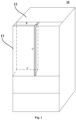
- FIG. 1 is a schematic perspective view of a refrigerator 10 having a storage space formed on a door body 11 according to an embodiment of the present invention.
- the refrigerator 10 having a storage space formed on a door body 11 may generally include a refrigerator body 12 and the door body 11.
- At least a first storage space (shielded by the door body 11 and unshown in the figure) is defined in the refrigerator body 12, where the first storage space has a forward opening.
- at least one storage space with an open front side is defined in the refrigerator body 12.
- a plurality of storage spaces are defined in the refrigerator body 12, where the storage spaces may be classified into a refrigeration chamber, a freezing chamber, a variable-temperature chamber and the like according to refrigeration temperatures and functions. Specific quantity and function of the storage space may be configured according to predetermined requirements.
- the first storage space may be one or more of a plurality of storage spaces defined by the refrigerator body 12.
- the door body 11 is disposed on a front side of the refrigerator body 12 to open and close a storage chamber.
- the door body 11 may be disposed on one side of a front portion of the refrigerator body 12 by means of hinging, to pivotally open and close the refrigerator body 12.
- the door body 11 may be configured according to layout of the refrigerator body 12.
- a layout structure of the refrigerator body 12 may be configured according to functions and requirements of the refrigerator, for example, the refrigerator body 12 may be configured as a side-by-side door type, a T type (cross door), a French type (four-door, or multi-door), or other types.
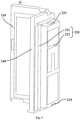
- FIG. 2 is a schematic diagram from one perspective of a door body 11 in the refrigerator 10 having a storage space formed on the door body 11 according to an embodiment of the present invention.
- FIG. 3 is a schematic diagram from another perspective of a door body 11 in the refrigerator 10 having a storage space formed on the door body 11 according to an embodiment of the present invention.
- FIG. 2 and FIG. 3 respectively show a front side structure and a rear side structure of the door body 11 when an outer-layer door 110 is open.
- the door body 11 may include an inner-layer door 200 and an outer-layer door 110.
- the inner-layer door 200 may be pivotally disposed at a front portion of the forward opening, and a second storage space 210 may be defined in the inner-layer door 200.
- the outer-layer door 110 may be pivotally disposed on one side of the inner-layer door 200 away from the refrigerator body 12, and is configured to open and close the opening of the second storage space 210. When the outer-layer door 110 is separately opened, the second storage space 210 may be exposed. In addition, the outer-layer door 110 and the inner-layer door 200 may be opened simultaneously to expose the first storage space defined by the refrigerator body 12. Since hinges and rotating structures of double-layer doors are well known to persons skilled in the art, they are not described in detail again in this embodiment.
- the second storage space 210 and the first storage space are independent of each other.
- cold energy leakage of the first storage space can be avoided.
- Smell in the first storage space and smell in the second storage space can also be prevented from being mixed during normal storage.
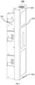
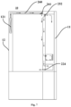
- FIG. 4 is a schematic diagram of an inner-layer door 200 in a refrigerator 10 according to an embodiment of the present invention.
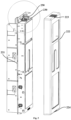
- FIG. 5 is a schematic exploded view of components of an inner-layer door 200 in a refrigerator 10 according to an embodiment of the present invention.
- FIG. 6 is a schematic locally enlarged view of a top of a storage container body 220 in the inner-layer door 200 shown in FIG. 5 .
- an inner-layer door frame 240 is hidden to show an internal structure of the inner-layer door 200.
- the inner-layer door 200 may include a storage container body 220, a sterilization module 230 and an inner-layer door frame 240.
- the storage container body 220 defines the second storage space 210; the second storage space 210 is provided with an opening in one side away from the refrigerator body 12; the storage container body 220 is provided with an air supply port 223 in one side toward the forward opening; and low-temperature air in the first storage space is introduced into the second storage space 210 via the air supply port 223 so as to implement refrigeration inside the second storage space 210.
- the sterilization module 230 is disposed at the air supply port 223 and is configured to sterilize the air passing through the air supply port 223.
- the inner-layer door frame 240 is disposed on the periphery of the storage container body 220, and sealing structures between the inner-layer door frame and the outer-layer door 110 and between the inner-layer door frame and the refrigerator body 12 are disposed at two sides of the inner-layer door frame 240, respectively.
- a hinge structure of the door body 11 is also disposed on one side of the inner-layer door frame.
- the scheme of this embodiment is characterized in that the second storage space 210 obtains refrigerating airflow through only the air supply port 223 provided in the storage container body 220, thus preventing direct communication between the second storage space 210 and the first storage space.
- the sterilization module 230 additionally arranged at the air supply port 223 can be used to sterilize refrigerating air introduced from the first storage space, thus preventing foods stored in the second storage space from being polluted by bacteria.
- the storage container body 220 may further include a container main body 221 and a housing 222.
- the container main body 221 is configured to constitute the second storage space 210, one side of the container main body 221 opposite to the refrigerator body 12 protrudes toward the forward opening, and the housing 222 covers a protruding portion of the container main body 221.
- the container main body 221 protrudes toward the refrigerator body 12.
- the housing 222 separates the first storage space and the second storage space 210.
- the housing 222 is at least partially made of a material with good thermal conductivity, such as metal, so that cooling transfer from the first storage space to the second storage space 210 is facilitated.
- the inner-layer door 200 further includes an air supply assembly 250.
- the air supply assembly 250 is disposed at the air supply port 223, and is configured to promote formation of a refrigerating airflow supplied from the first storage space to the second storage space 210.
- the housing 222 and the top of the container main body 221 form a mounting chamber; in addition, the air supply port 223 is formed in the top of the housing 222; and the air supply assembly 250 is disposed inside the mounting chamber and opposite the air supply port 223.
- Such mounting structure reduces space occupied by the air supply assembly 250 and increases a utilization rate of the second storage space 210.
- the air supply assembly 250 may include a fan bracket 251 and an air supply fan 252.
- the fan bracket 251 is disposed at a top wall of the container main body 221 and extends upwards.
- the air supply fan 252 is mounted on the fan bracket 251, and the top wall of the container main body 221 is provided with a communicating opening below the air supply fan 252.
- the air supply fan 252 may be turned on or off in a controlled way. After turned on, it can suck air from the air supply port 223 and then supply the air to the second storage space 210 via the communicating opening.
- the air supply fan 252 may preferably adopt an axial-flow fan with its axis parallel to an extension direction of the communicating opening and the air supply port 223, thus reducing space occupied by the fan. Persons skilled in the art can select other types of fans as required.
- the storage container body 220 may further be provided with a grating plate (unshown in the figures), where the grating plate is disposed at the communicating opening, so as to visually shield the air supply assembly 250.
- the fan bracket 251 enables a specified space between the air supply fan 252 and the top wall of the container main body 221.
- the sterilization module 230 may be mounted in the space, that is, the sterilization module 230 is mounted between the air supply fan 252 and the communicating opening, so that sterilization can be performed before an air flow passes through the communicating opening.
- the sterilization module 230 may adopt a negative-ion generator, and a similar sterilization effect can be achieved by using technologies such as UV sterilization and filter adhesive membranes.
- the sterilization module 230 may include a plurality of negative-ion emitters that are oppositely spaced apart below the air supply fan 252.
- the sterilization module 230 may be turned on or off along with the air supply fan 252, for example, the sterilization module 230 is pre-started before the air supply fan 252 is turned on, and turning off of the sterilization module 230 is delayed after the air supply fan 252 is turned off, such that cleanness of the second storage space 210 is guaranteed.
- the storage container body 220 may further include at least one dividing element 211.
- the dividing element 211 is configured to divide the second storage space 210 into a plurality of storage areas.
- the quantity and structure of the storage areas may be configured according to a storage requirement.
- at least one storage area may be configured as a sealed drawer 212, where the sealed drawer 212 may be configured to implement dry-area storage, preservation and the like.
- One or more sealed drawers 212 may be provided, and a specific quantity thereof may be configured according to the storage requirement.
- An internal structure of the second storage space 210 is improved, such that a plurality of storage areas are formed in the second storage space 210, and a sealed drawer 212 may be further formed, greatly expanding use flexibility of the second storage space 210.
- FIG. 7 is a schematic diagram showing that a refrigerating airflow is supplied to a door body 11 of a refrigerator 10 according to an embodiment of the present invention.
- a special air supply duct 260 may be disposed in the refrigerator body 12.
- the air supply duct 260 extends from a refrigeration chamber 121 of the refrigerator 10 to a front portion of a top wall of the refrigerator body 12, and forms an air duct opening 261 at a position opposite the air supply port 223, such that an airflow supplied by the air supply duct 260 is at least partially discharged into the air supply port 223.
- a part of airflow discharged from the air duct opening 261 may be discharged into the second storage space 210 to refrigerate the second storage space 210, and the remaining part of airflow discharged from the air duct opening 261 may be partially discharged into the front portion of the first storage space, such that a temperature in the first storage space is equalized.
- the bottom of the second storage space 210 may further be provided with a door body air return port via which the air in the second storage space 210 can return to the first storage space, thus forming an airflow cycle.
- the second storage space 210 and the first storage space behind can both be configured as a refrigeration storage space.
- space division storage requirements for different objects are met.
- the internal structure of the second storage space 210 is improved, such that a plurality of storage areas are formed in the second storage space 210, and a sealed drawer 212 may be further formed, greatly expanding use flexibility of the second storage space 210.
Landscapes
- Engineering & Computer Science (AREA)
- Chemical & Material Sciences (AREA)
- Combustion & Propulsion (AREA)
- Physics & Mathematics (AREA)
- Mechanical Engineering (AREA)
- Thermal Sciences (AREA)
- General Engineering & Computer Science (AREA)
- Cold Air Circulating Systems And Constructional Details In Refrigerators (AREA)
Abstract
Description
- The present invention relates to a refrigerator, and particularly to a refrigerator having a storage space formed on a door body.
- In an existing refrigerator, a storage space is generally formed by a refrigerator body, and is opened and closed through a door body. Such conventional spatial structure causes inflexibility of space division. Especially for a large-capacity refrigerator, the storage space cannot be fully used. In addition, it is likely to cause cold energy leakage when a user opens and closes the door body to take and put objects.
- To fully use the space of the refrigerator, door-in-door structures have emerged in the prior art, that is, a door body includes an inner-layer door and an outer-layer door. The inner-layer door is configured to seal the space of a refrigerator body, and the inner-layer door itself includes a storage space as well. The outer-layer door is configured to seal the storage space on the inner-layer door. When needing to take or put objects on the inner-layer door, a user just needs to open the outer-layer door. This improves layout flexibility of the storage space.
- However, in an existing door-in-door type refrigerator, the storage space on the inner-layer door is generally in direct communication with the storage space of the refrigerator body. After the outer-layer door is opened, it is still likely to cause cold energy leakage of the storage space of the refrigerator body. In addition, smell in the storage space of the inner-layer door and smell in the storage space of the refrigerator body are likely to be mixed with each other. Moreover, if there is spoiled food, bacteria will spread in the overall refrigerator.
- A purpose of the present invention is to provide a refrigerator in which a storage space of a door body and a storage space of a refrigerator body are independent of each other.
- A further purpose of the present invention is to prevent spreading of bacteria between the storage space of the door body and the storage space of the refrigerator body.
- In particular, the present invention provides a refrigerator having a storage space formed on a door body, and the refrigerator includes:
- a refrigerator body, inside which at least a first storage space is defined, where the first storage space has a forward opening;
- an inner-layer door, pivotally disposed at a front portion of the forward opening and including a storage container body, where the storage container body defines a second storage space, the second storage space is provided with an opening in one side away from the refrigerator body, the storage container body is provided with an air supply port in one side toward the forward opening, and low-temperature air in the first storage space is introduced into the second storage space via the air supply port to implement refrigeration inside the second storage space; a sterilization module, disposed at the air supply port and configured to sterilize the air passing through the air supply port;
- an inner-layer door frame, disposed on the periphery of the storage container body; and
- an outer-layer door, pivotally disposed on one side of the inner-layer door frame away from the refrigerator body and configured to open and close the opening of the second storage space.
- Optionally, the inner-layer door further includes an air supply assembly, where the air supply assembly is disposed at the air supply port and is configured to promote formation of a refrigerating airflow supplied from the first storage space to the second storage space.
- Optionally, the storage container body includes:
- a container main body, where the container main body is configured to constitute the second storage space, and one side of the container main body opposite to the refrigerator body protrudes toward the forward opening; and
- a housing, where the housing covers a protruding portion of the container main body; the housing and the top of the container main body form a mounting chamber; and the air supply port is formed in the top of the housing, and the air supply assembly is disposed inside the mounting chamber and opposite the air supply port.
- Optionally, the air supply assembly includes: a fan bracket disposed at a top wall of the container main body, and an air supply fan mounted on the fan bracket, where the top wall of the container main body is provided with a communicating opening below the air supply fan.
- Optionally, the sterilization module is mounted between the air supply fan and the communicating opening.
- Optionally, the sterilization module is a negative-ion generator and includes a plurality of negative-ion emitters that are oppositely spaced apart below the air supply fan.
- Optionally, the storage container body further includes a grating plate disposed at the communicating opening.
- Optionally, the refrigerator body is further internally provided with an air supply duct, where the air supply duct extends from a refrigeration chamber of the refrigerator to a front portion of a top wall of the refrigerator body, and forms an air duct opening at a position opposite the air supply port, so that an airflow provided by the air supply duct is at least partially discharged into the air supply port.
- Optionally, the storage container body further includes at least one dividing element configured to divide the second storage space into a plurality of storage areas.
- Optionally, at least one of the storage areas is configured as a sealed drawer.
- According to the refrigerator having a storage space formed on a door body in the present invention, the inner-layer door defines a second storage space by using the storage container body; the second storage space is provided with an opening in one side away from the refrigerator body, so that when the door body is closed, the second storage space on the door body is independent of the first storage space of the refrigerator body, avoiding cold energy leakage of the first storage space caused when the second storage space is opened, and also preventing smell in the first storage space from being mixed with smell in the second storage space during normal storage. In addition, the refrigerator provided by the present invention is additionally provided with the sterilization module at the air supply port, to sterilize refrigerating air introduced from the first storage space, thus preventing foods stored in the second storage space from being polluted by bacteria.
- Further, the refrigerator having a storage space formed on a door body in the present invention is provided with the air supply assembly, where the air supply assembly is used to promote formation of a refrigerating airflow supplied from the first storage space to the second storage space. In addition, mounting positions and mounting structures for the air supply assembly and the sterilization module are optimized, thereby improving structural compactness and guaranteeing an available volume of the second storage space and reliability of refrigeration.
- More further, according to the refrigerator having a storage space formed on a door body in the present invention, an internal structure of the second storage space is improved, such that a plurality of storage areas are formed in the second storage space, and a sealed drawer may be further formed, greatly expanding use flexibility of the second storage space.
- Specific embodiments of the present invention are described below in detail with reference to the accompanying drawings, and persons skilled in the art can more clearly understand the above and other purposes, advantages and features of the present invention.
- Some specific embodiments of the present invention are described below in detail in an exemplary and unlimited way with reference to the accompanying drawings. The same or similar components or parts are indicated by the same reference numerals in the drawings. Persons skilled in the art should understand that these drawings are not necessarily drawn to scale. In the drawings:
-
FIG. 1 is a schematic perspective view of a refrigerator having a storage space formed on a door body according to an embodiment of the present invention; -
FIG. 2 is a schematic diagram from one perspective of a door body in a refrigerator having a storage space formed on the door body according to an embodiment of the present invention; -
FIG. 3 is a schematic diagram from another perspective of a door body in a refrigerator having a storage space formed on the door body according to an embodiment of the present invention; -
FIG. 4 is a schematic diagram of an inner-layer door in a refrigerator according to an embodiment of the present invention; -
FIG. 5 is a schematic exploded view of an inner-layer door in a refrigerator according to an embodiment of the present invention; -
FIG. 6 is a schematic locally enlarged view of a top of a storage container body in the inner-layer door shown inFIG. 5 ; and -
FIG. 7 is a schematic diagram showing that a refrigerating airflow is supplied to a door body of a refrigerator according to an embodiment of the present invention; - In the descriptions of the present invention, it should be understood that the orientations or positional relationships indicated by the terms "up", "down", "front", "rear", "top", "bottom" and the like are based on the orientations or positional relationships shown in the accompanying drawings. Such terms are intended merely for the ease and brevity of description of the present invention without indicating or implying that the apparatuses or components mentioned must have specified orientations or must be constructed and manipulated in the specified orientations, and therefore shall not be construed as any limitation on the present invention. That is, if the embodiments of the present invention involve orientation indication (such as up, down, front, rear, top, bottom......), the orientation indication is merely for explaining a relative positional relationship between components in a certain posture (for example, as shown in the accompanying drawings, or as a normal use state of the refrigerator).
-
FIG. 1 is a schematic perspective view of arefrigerator 10 having a storage space formed on adoor body 11 according to an embodiment of the present invention. Therefrigerator 10 having a storage space formed on adoor body 11 may generally include arefrigerator body 12 and thedoor body 11. - At least a first storage space (shielded by the
door body 11 and unshown in the figure) is defined in therefrigerator body 12, where the first storage space has a forward opening. Generally, at least one storage space with an open front side is defined in therefrigerator body 12. Usually, a plurality of storage spaces are defined in therefrigerator body 12, where the storage spaces may be classified into a refrigeration chamber, a freezing chamber, a variable-temperature chamber and the like according to refrigeration temperatures and functions. Specific quantity and function of the storage space may be configured according to predetermined requirements. The first storage space may be one or more of a plurality of storage spaces defined by therefrigerator body 12. - The
door body 11 is disposed on a front side of therefrigerator body 12 to open and close a storage chamber. For example, thedoor body 11 may be disposed on one side of a front portion of therefrigerator body 12 by means of hinging, to pivotally open and close therefrigerator body 12. Thedoor body 11 may be configured according to layout of therefrigerator body 12. A layout structure of therefrigerator body 12 may be configured according to functions and requirements of the refrigerator, for example, therefrigerator body 12 may be configured as a side-by-side door type, a T type (cross door), a French type (four-door, or multi-door), or other types. - In the
refrigerator 10 having a storage space formed on thedoor body 11 in this embodiment, the first storage space defined by therefrigerator body 12 has a forward opening, and is sealed by a double-layer door (or referred to as a door-in-door).FIG. 2 is a schematic diagram from one perspective of adoor body 11 in therefrigerator 10 having a storage space formed on thedoor body 11 according to an embodiment of the present invention.FIG. 3 is a schematic diagram from another perspective of adoor body 11 in therefrigerator 10 having a storage space formed on thedoor body 11 according to an embodiment of the present invention.FIG. 2 andFIG. 3 respectively show a front side structure and a rear side structure of thedoor body 11 when an outer-layer door 110 is open. - The
door body 11 may include an inner-layer door 200 and an outer-layer door 110. The inner-layer door 200 may be pivotally disposed at a front portion of the forward opening, and asecond storage space 210 may be defined in the inner-layer door 200. The outer-layer door 110 may be pivotally disposed on one side of the inner-layer door 200 away from therefrigerator body 12, and is configured to open and close the opening of thesecond storage space 210. When the outer-layer door 110 is separately opened, thesecond storage space 210 may be exposed. In addition, the outer-layer door 110 and the inner-layer door 200 may be opened simultaneously to expose the first storage space defined by therefrigerator body 12. Since hinges and rotating structures of double-layer doors are well known to persons skilled in the art, they are not described in detail again in this embodiment. - In the
refrigerator 10 in this embodiment, thesecond storage space 210 and the first storage space are independent of each other. When the outer-layer door 110 is separately opened, cold energy leakage of the first storage space can be avoided. Smell in the first storage space and smell in the second storage space can also be prevented from being mixed during normal storage. -
FIG. 4 is a schematic diagram of an inner-layer door 200 in arefrigerator 10 according to an embodiment of the present invention.FIG. 5 is a schematic exploded view of components of an inner-layer door 200 in arefrigerator 10 according to an embodiment of the present invention.FIG. 6 is a schematic locally enlarged view of a top of astorage container body 220 in the inner-layer door 200 shown inFIG. 5 . InFIGS. 4 ,5 and6 , an inner-layer door frame 240 is hidden to show an internal structure of the inner-layer door 200. - The inner-
layer door 200 may include astorage container body 220, asterilization module 230 and an inner-layer door frame 240. Thestorage container body 220 defines thesecond storage space 210; thesecond storage space 210 is provided with an opening in one side away from therefrigerator body 12; thestorage container body 220 is provided with anair supply port 223 in one side toward the forward opening; and low-temperature air in the first storage space is introduced into thesecond storage space 210 via theair supply port 223 so as to implement refrigeration inside thesecond storage space 210. Thesterilization module 230 is disposed at theair supply port 223 and is configured to sterilize the air passing through theair supply port 223. The inner-layer door frame 240 is disposed on the periphery of thestorage container body 220, and sealing structures between the inner-layer door frame and the outer-layer door 110 and between the inner-layer door frame and therefrigerator body 12 are disposed at two sides of the inner-layer door frame 240, respectively. In addition, a hinge structure of thedoor body 11 is also disposed on one side of the inner-layer door frame. - In comparison with a double-door refrigerator in the prior art, in which a rear side of the storage space of the inner-
layer door 200 is in direct communication with therefrigerator body 12, the scheme of this embodiment is characterized in that thesecond storage space 210 obtains refrigerating airflow through only theair supply port 223 provided in thestorage container body 220, thus preventing direct communication between thesecond storage space 210 and the first storage space. In addition, thesterilization module 230 additionally arranged at theair supply port 223 can be used to sterilize refrigerating air introduced from the first storage space, thus preventing foods stored in the second storage space from being polluted by bacteria. - The
storage container body 220 may further include a containermain body 221 and ahousing 222. The containermain body 221 is configured to constitute thesecond storage space 210, one side of the containermain body 221 opposite to therefrigerator body 12 protrudes toward the forward opening, and thehousing 222 covers a protruding portion of the containermain body 221. To increase a volume of thesecond storage space 210, the containermain body 221 protrudes toward therefrigerator body 12. As a rear wall of thestorage container body 220, thehousing 222 separates the first storage space and thesecond storage space 210. - The
housing 222 is at least partially made of a material with good thermal conductivity, such as metal, so that cooling transfer from the first storage space to thesecond storage space 210 is facilitated. - To further meet a refrigeration requirement of the
second storage space 210, the inner-layer door 200 further includes anair supply assembly 250. Theair supply assembly 250 is disposed at theair supply port 223, and is configured to promote formation of a refrigerating airflow supplied from the first storage space to thesecond storage space 210. - The
housing 222 and the top of the containermain body 221 form a mounting chamber; in addition, theair supply port 223 is formed in the top of thehousing 222; and theair supply assembly 250 is disposed inside the mounting chamber and opposite theair supply port 223. Such mounting structure reduces space occupied by theair supply assembly 250 and increases a utilization rate of thesecond storage space 210. - The
air supply assembly 250 may include afan bracket 251 and anair supply fan 252. Thefan bracket 251 is disposed at a top wall of the containermain body 221 and extends upwards. Theair supply fan 252 is mounted on thefan bracket 251, and the top wall of the containermain body 221 is provided with a communicating opening below theair supply fan 252. Theair supply fan 252 may be turned on or off in a controlled way. After turned on, it can suck air from theair supply port 223 and then supply the air to thesecond storage space 210 via the communicating opening. Theair supply fan 252 may preferably adopt an axial-flow fan with its axis parallel to an extension direction of the communicating opening and theair supply port 223, thus reducing space occupied by the fan. Persons skilled in the art can select other types of fans as required. - To prevent an internal structure of the
air supply assembly 250 from being seen by a user from the front portion of the inner-layer door 200 via the communicating opening and improve the appearance aesthetics of thedoor body 11, thestorage container body 220 may further be provided with a grating plate (unshown in the figures), where the grating plate is disposed at the communicating opening, so as to visually shield theair supply assembly 250. - The
fan bracket 251 enables a specified space between theair supply fan 252 and the top wall of the containermain body 221. Thesterilization module 230 may be mounted in the space, that is, thesterilization module 230 is mounted between theair supply fan 252 and the communicating opening, so that sterilization can be performed before an air flow passes through the communicating opening. - The
sterilization module 230 may adopt a negative-ion generator, and a similar sterilization effect can be achieved by using technologies such as UV sterilization and filter adhesive membranes. In an embodiment in which a negative-ion generator is used, thesterilization module 230 may include a plurality of negative-ion emitters that are oppositely spaced apart below theair supply fan 252. - The
sterilization module 230 may be turned on or off along with theair supply fan 252, for example, thesterilization module 230 is pre-started before theair supply fan 252 is turned on, and turning off of thesterilization module 230 is delayed after theair supply fan 252 is turned off, such that cleanness of thesecond storage space 210 is guaranteed. - The
storage container body 220 may further include at least one dividingelement 211. The dividingelement 211 is configured to divide thesecond storage space 210 into a plurality of storage areas. The quantity and structure of the storage areas may be configured according to a storage requirement. In some embodiments, at least one storage area may be configured as a sealeddrawer 212, where the sealeddrawer 212 may be configured to implement dry-area storage, preservation and the like. One or moresealed drawers 212 may be provided, and a specific quantity thereof may be configured according to the storage requirement. - An internal structure of the
second storage space 210 is improved, such that a plurality of storage areas are formed in thesecond storage space 210, and a sealeddrawer 212 may be further formed, greatly expanding use flexibility of thesecond storage space 210. -
FIG. 7 is a schematic diagram showing that a refrigerating airflow is supplied to adoor body 11 of arefrigerator 10 according to an embodiment of the present invention. A specialair supply duct 260 may be disposed in therefrigerator body 12. Theair supply duct 260 extends from arefrigeration chamber 121 of therefrigerator 10 to a front portion of a top wall of therefrigerator body 12, and forms anair duct opening 261 at a position opposite theair supply port 223, such that an airflow supplied by theair supply duct 260 is at least partially discharged into theair supply port 223. A part of airflow discharged from theair duct opening 261 may be discharged into thesecond storage space 210 to refrigerate thesecond storage space 210, and the remaining part of airflow discharged from theair duct opening 261 may be partially discharged into the front portion of the first storage space, such that a temperature in the first storage space is equalized. The bottom of thesecond storage space 210 may further be provided with a door body air return port via which the air in thesecond storage space 210 can return to the first storage space, thus forming an airflow cycle. - In this embodiment, the
second storage space 210 and the first storage space behind can both be configured as a refrigeration storage space. By space division, storage requirements for different objects are met. - According to the
refrigerator 10 having a storage space formed on a door body in this embodiment, the internal structure of thesecond storage space 210 is improved, such that a plurality of storage areas are formed in thesecond storage space 210, and a sealeddrawer 212 may be further formed, greatly expanding use flexibility of thesecond storage space 210. - In conclusion, it should be learned by those skilled in the art that although various exemplary embodiments of the present invention have been illustrated and described in detail herein, many other variations or modifications consistent with the principles of the present invention may be directly determined or derived from the disclosure of the present invention without departing from the spirit and scope of the present invention. Therefore, the scope of the present invention should be construed and considered as covering all these other variations or modifications.
Claims (10)
- A refrigerator having a storage space formed on a door body, comprising:a refrigerator body, wherein at least a first storage space is defined in the refrigerator body, and the first storage space has a forward opening;an inner-layer door, pivotally disposed at a front portion of the forward opening and comprising:a storage container body, wherein the storage container body defines a second storage space, the second storage space is provided with an opening in one side away from the refrigerator body, the storage container body is provided with an air supply port in one side toward the forward opening, and low-temperature air in the first storage space is introduced into the second storage space via the air supply port to implement refrigeration inside the second storage space;a sterilization module, disposed at the air supply port and configured to sterilize the air passing through the air supply port; andan inner-layer door frame, disposed on the periphery of the storage container body; andan outer-layer door, pivotally disposed on one side of the inner-layer door frame away from the refrigerator body and configured to open and close the opening of the second storage space.
- The refrigerator having a storage space formed on a door body according to claim 1, wherein the inner-layer door further comprises:
an air supply assembly, disposed at the air supply port and configured to promote formation of a refrigerating airflow supplied from the first storage space to the second storage space. - The refrigerator having a storage space formed on a door body according to claim 2, wherein the storage container body comprises:a container main body, wherein the container main body is configured to constitute the second storage space, and one side of the container main body opposite to the refrigerator body protrudes toward the forward opening; anda housing, wherein the housing covers a protruding portion of the container main body; the housing and the top of the container main body form a mounting chamber; andthe air supply port is formed in the top of the housing, and the air supply assembly is disposed inside the mounting chamber and opposite the air supply port.
- The refrigerator having a storage space formed on a door body according to claim 3, wherein the air supply assembly comprises:a fan bracket, disposed at a top wall of the container main body; andan air supply fan, installed on the fan bracket, whereinthe top wall of the container main body is provided with a communicating opening below the air supply fan.
- The refrigerator having a storage space formed on a door body according to claim 4, wherein
the sterilization module is mounted between the air supply fan and the communicating opening. - The refrigerator having a storage space formed on a door body according to claim 5, wherein
the sterilization module is a negative-ion generator and comprises a plurality of negative-ion emitters that are oppositely spaced apart below the air supply fan. - The refrigerator having a storage space formed on a door body according to claim 4, wherein the storage container body further comprises:
a grating plate disposed at the communicating opening. - The refrigerator having a storage space formed on a door body according to claim 3, wherein the refrigerator body is further internally provided with:
an air supply duct, which extends from a refrigeration chamber of the refrigerator to a front portion of a top wall of the refrigerator body, and forms an air duct opening at a position opposite the air supply port, such that an airflow supplied by the air supply duct is at least partially discharged into the air supply port. - The refrigerator having a storage space formed on a door body according to claim 1, wherein the storage container body further comprises:
at least one dividing element, configured to divide the second storage space into a plurality of storage areas. - The refrigerator having a storage space formed on a door body according to claim 9, wherein
at least one of the storage areas is configured as a sealed drawer.
Applications Claiming Priority (2)
| Application Number | Priority Date | Filing Date | Title |
|---|---|---|---|
| CN202010969229.1A CN114183967B (en) | 2020-09-15 | 2020-09-15 | Refrigerator with storage space formed on the door |
| PCT/CN2021/115633 WO2022057613A1 (en) | 2020-09-15 | 2021-08-31 | Refrigerator having storage space formed on door body |
Publications (3)
| Publication Number | Publication Date |
|---|---|
| EP4206583A1 true EP4206583A1 (en) | 2023-07-05 |
| EP4206583A4 EP4206583A4 (en) | 2024-02-21 |
| EP4206583B1 EP4206583B1 (en) | 2024-10-23 |
Family
ID=80539197
Family Applications (1)
| Application Number | Title | Priority Date | Filing Date |
|---|---|---|---|
| EP21868440.5A Active EP4206583B1 (en) | 2020-09-15 | 2021-08-31 | Refrigerator having storage space formed on door body |
Country Status (4)
| Country | Link |
|---|---|
| US (1) | US12498162B2 (en) |
| EP (1) | EP4206583B1 (en) |
| CN (1) | CN114183967B (en) |
| WO (1) | WO2022057613A1 (en) |
Families Citing this family (1)
| Publication number | Priority date | Publication date | Assignee | Title |
|---|---|---|---|---|
| AU2023289275B2 (en) * | 2022-06-23 | 2025-12-18 | Lg Electronics Inc. | Refrigerator |
Family Cites Families (17)
| Publication number | Priority date | Publication date | Assignee | Title |
|---|---|---|---|---|
| JPS63142682U (en) * | 1987-03-09 | 1988-09-20 | ||
| JPS63142692U (en) | 1987-03-09 | 1988-09-20 | ||
| JP2000065459A (en) * | 1998-08-25 | 2000-03-03 | Fujitsu General Ltd | Freezer refrigerator |
| JP2001255054A (en) * | 2000-03-14 | 2001-09-21 | Hakugen:Kk | Refrigerator curtains |
| JP4416932B2 (en) * | 2000-10-06 | 2010-02-17 | 三菱電機株式会社 | Freezer refrigerator |
| AU2003298498A1 (en) * | 2002-12-31 | 2004-07-22 | Arcelik A.S. | Refrigerator |
| KR20120092442A (en) * | 2011-02-11 | 2012-08-21 | 삼성전자주식회사 | Refrigerator |
| EP3508804B1 (en) * | 2011-08-05 | 2023-03-01 | LG Electronics Inc. | Refrigerator with inner door |
| CN104075532A (en) * | 2013-03-29 | 2014-10-01 | 海尔集团公司 | Air-cooled refrigerator |
| CN104807274A (en) * | 2015-04-29 | 2015-07-29 | 青岛海尔股份有限公司 | Refrigerator |
| JP6804832B2 (en) * | 2015-07-21 | 2020-12-23 | 東芝ライフスタイル株式会社 | refrigerator |
| CN105167110B (en) * | 2015-09-28 | 2019-12-10 | 青岛海尔股份有限公司 | Sterile purifying and fresh-keeping device, sterilizing method and refrigerator |
| KR102409750B1 (en) * | 2015-11-02 | 2022-06-17 | 엘지전자 주식회사 | Refrigerator |
| BR112018016324A2 (en) * | 2016-02-12 | 2018-12-18 | Anheuser-Busch Inbev S.A. | sectorized cooling arrangement |
| US20200378678A1 (en) * | 2017-12-28 | 2020-12-03 | Whirlpool Corporation | Storage structure for an appliance |
| US11022361B2 (en) * | 2018-08-29 | 2021-06-01 | Whirlpool Corporation | Air filtration system for antimicrobial refrigerators |
| CN212378330U (en) * | 2020-09-15 | 2021-01-19 | 青岛海尔电冰箱有限公司 | Refrigerator with storage space formed on door body |
-
2020
- 2020-09-15 CN CN202010969229.1A patent/CN114183967B/en active Active
-
2021
- 2021-08-31 US US18/245,328 patent/US12498162B2/en active Active
- 2021-08-31 EP EP21868440.5A patent/EP4206583B1/en active Active
- 2021-08-31 WO PCT/CN2021/115633 patent/WO2022057613A1/en not_active Ceased
Also Published As
| Publication number | Publication date |
|---|---|
| WO2022057613A1 (en) | 2022-03-24 |
| US20230384017A1 (en) | 2023-11-30 |
| US12498162B2 (en) | 2025-12-16 |
| CN114183967B (en) | 2025-10-10 |
| EP4206583B1 (en) | 2024-10-23 |
| EP4206583A4 (en) | 2024-02-21 |
| CN114183967A (en) | 2022-03-15 |
Similar Documents
| Publication | Publication Date | Title |
|---|---|---|
| CN210267852U (en) | Refrigerator with air supply fan at downstream of evaporator | |
| CN102362135B (en) | Refrigerator storeroom assembly | |
| AU742491B2 (en) | Refrigerator | |
| CA2757470C (en) | Refrigerator | |
| EP3132214B1 (en) | Refrigerator | |
| US20040261444A1 (en) | Methods and apparatus for refrigerator compartment | |
| KR20020004962A (en) | Refrigerator | |
| CN212378330U (en) | Refrigerator with storage space formed on door body | |
| WO2020160697A1 (en) | Refrigerator appliance with direct-cooled in-door chamber | |
| EP4206572B1 (en) | Refrigerator | |
| CN1802542B (en) | refrigerator | |
| US12498162B2 (en) | Refrigerator having storage space formed on door body | |
| EP4206571B1 (en) | Refrigerator provided with sealed drawer on door body | |
| CN114061252B (en) | Control methods of air-cooled refrigerators and air-cooled refrigerators | |
| CN111609608B (en) | A refrigerator with dual air blowers | |
| KR101146274B1 (en) | Thermostatic control device for vegetalbe chamber of two-door type refrigerator | |
| EP4006457B1 (en) | Refrigerator capable of improving air circulation in machine chamber | |
| JP2002130914A (en) | Pickle storage and its solenoid valve mounting structure | |
| CN213778313U (en) | Refrigerator with a door | |
| CN209101655U (en) | Refrigerator | |
| CN208520064U (en) | With the refrigerator that can be detached from heat preservation module | |
| KR20050028773A (en) | Refrigerator | |
| KR200396683Y1 (en) | Refrigerator having front and rear door | |
| KR970005793Y1 (en) | Refrigerator with dining table | |
| JP2001033142A (en) | refrigerator |
Legal Events
| Date | Code | Title | Description |
|---|---|---|---|
| STAA | Information on the status of an ep patent application or granted ep patent |
Free format text: STATUS: THE INTERNATIONAL PUBLICATION HAS BEEN MADE |
|
| PUAI | Public reference made under article 153(3) epc to a published international application that has entered the european phase |
Free format text: ORIGINAL CODE: 0009012 |
|
| STAA | Information on the status of an ep patent application or granted ep patent |
Free format text: STATUS: REQUEST FOR EXAMINATION WAS MADE |
|
| 17P | Request for examination filed |
Effective date: 20230330 |
|
| AK | Designated contracting states |
Kind code of ref document: A1 Designated state(s): AL AT BE BG CH CY CZ DE DK EE ES FI FR GB GR HR HU IE IS IT LI LT LU LV MC MK MT NL NO PL PT RO RS SE SI SK SM TR |
|
| DAV | Request for validation of the european patent (deleted) | ||
| DAX | Request for extension of the european patent (deleted) | ||
| STAA | Information on the status of an ep patent application or granted ep patent |
Free format text: STATUS: EXAMINATION IS IN PROGRESS |
|
| A4 | Supplementary search report drawn up and despatched |
Effective date: 20240122 |
|
| RIC1 | Information provided on ipc code assigned before grant |
Ipc: F25D 17/06 20060101ALI20240116BHEP Ipc: F25D 23/02 20060101AFI20240116BHEP |
|
| 17Q | First examination report despatched |
Effective date: 20240202 |
|
| GRAP | Despatch of communication of intention to grant a patent |
Free format text: ORIGINAL CODE: EPIDOSNIGR1 |
|
| STAA | Information on the status of an ep patent application or granted ep patent |
Free format text: STATUS: GRANT OF PATENT IS INTENDED |
|
| INTG | Intention to grant announced |
Effective date: 20240712 |
|
| GRAS | Grant fee paid |
Free format text: ORIGINAL CODE: EPIDOSNIGR3 |
|
| GRAA | (expected) grant |
Free format text: ORIGINAL CODE: 0009210 |
|
| STAA | Information on the status of an ep patent application or granted ep patent |
Free format text: STATUS: THE PATENT HAS BEEN GRANTED |
|
| AK | Designated contracting states |
Kind code of ref document: B1 Designated state(s): AL AT BE BG CH CY CZ DE DK EE ES FI FR GB GR HR HU IE IS IT LI LT LU LV MC MK MT NL NO PL PT RO RS SE SI SK SM TR |
|
| REG | Reference to a national code |
Ref country code: GB Ref legal event code: FG4D |
|
| REG | Reference to a national code |
Ref country code: CH Ref legal event code: EP |
|
| REG | Reference to a national code |
Ref country code: DE Ref legal event code: R096 Ref document number: 602021020817 Country of ref document: DE |
|
| REG | Reference to a national code |
Ref country code: IE Ref legal event code: FG4D |
|
| REG | Reference to a national code |
Ref country code: LT Ref legal event code: MG9D |
|
| REG | Reference to a national code |
Ref country code: NL Ref legal event code: MP Effective date: 20241023 |
|
| REG | Reference to a national code |
Ref country code: AT Ref legal event code: MK05 Ref document number: 1735158 Country of ref document: AT Kind code of ref document: T Effective date: 20241023 |
|
| PG25 | Lapsed in a contracting state [announced via postgrant information from national office to epo] |
Ref country code: NL Free format text: LAPSE BECAUSE OF FAILURE TO SUBMIT A TRANSLATION OF THE DESCRIPTION OR TO PAY THE FEE WITHIN THE PRESCRIBED TIME-LIMIT Effective date: 20241023 |
|
| PG25 | Lapsed in a contracting state [announced via postgrant information from national office to epo] |
Ref country code: NL Free format text: LAPSE BECAUSE OF FAILURE TO SUBMIT A TRANSLATION OF THE DESCRIPTION OR TO PAY THE FEE WITHIN THE PRESCRIBED TIME-LIMIT Effective date: 20241023 |
|
| PG25 | Lapsed in a contracting state [announced via postgrant information from national office to epo] |
Ref country code: HR Free format text: LAPSE BECAUSE OF FAILURE TO SUBMIT A TRANSLATION OF THE DESCRIPTION OR TO PAY THE FEE WITHIN THE PRESCRIBED TIME-LIMIT Effective date: 20241023 Ref country code: IS Free format text: LAPSE BECAUSE OF FAILURE TO SUBMIT A TRANSLATION OF THE DESCRIPTION OR TO PAY THE FEE WITHIN THE PRESCRIBED TIME-LIMIT Effective date: 20250223 Ref country code: PT Free format text: LAPSE BECAUSE OF FAILURE TO SUBMIT A TRANSLATION OF THE DESCRIPTION OR TO PAY THE FEE WITHIN THE PRESCRIBED TIME-LIMIT Effective date: 20250224 |
|
| PG25 | Lapsed in a contracting state [announced via postgrant information from national office to epo] |
Ref country code: FI Free format text: LAPSE BECAUSE OF FAILURE TO SUBMIT A TRANSLATION OF THE DESCRIPTION OR TO PAY THE FEE WITHIN THE PRESCRIBED TIME-LIMIT Effective date: 20241023 |
|
| PG25 | Lapsed in a contracting state [announced via postgrant information from national office to epo] |
Ref country code: BG Free format text: LAPSE BECAUSE OF FAILURE TO SUBMIT A TRANSLATION OF THE DESCRIPTION OR TO PAY THE FEE WITHIN THE PRESCRIBED TIME-LIMIT Effective date: 20241023 |
|
| PG25 | Lapsed in a contracting state [announced via postgrant information from national office to epo] |
Ref country code: ES Free format text: LAPSE BECAUSE OF FAILURE TO SUBMIT A TRANSLATION OF THE DESCRIPTION OR TO PAY THE FEE WITHIN THE PRESCRIBED TIME-LIMIT Effective date: 20241023 |
|
| PG25 | Lapsed in a contracting state [announced via postgrant information from national office to epo] |
Ref country code: NO Free format text: LAPSE BECAUSE OF FAILURE TO SUBMIT A TRANSLATION OF THE DESCRIPTION OR TO PAY THE FEE WITHIN THE PRESCRIBED TIME-LIMIT Effective date: 20250123 |
|
| PG25 | Lapsed in a contracting state [announced via postgrant information from national office to epo] |
Ref country code: LV Free format text: LAPSE BECAUSE OF FAILURE TO SUBMIT A TRANSLATION OF THE DESCRIPTION OR TO PAY THE FEE WITHIN THE PRESCRIBED TIME-LIMIT Effective date: 20241023 Ref country code: AT Free format text: LAPSE BECAUSE OF FAILURE TO SUBMIT A TRANSLATION OF THE DESCRIPTION OR TO PAY THE FEE WITHIN THE PRESCRIBED TIME-LIMIT Effective date: 20241023 Ref country code: GR Free format text: LAPSE BECAUSE OF FAILURE TO SUBMIT A TRANSLATION OF THE DESCRIPTION OR TO PAY THE FEE WITHIN THE PRESCRIBED TIME-LIMIT Effective date: 20250124 |
|
| PG25 | Lapsed in a contracting state [announced via postgrant information from national office to epo] |
Ref country code: PL Free format text: LAPSE BECAUSE OF FAILURE TO SUBMIT A TRANSLATION OF THE DESCRIPTION OR TO PAY THE FEE WITHIN THE PRESCRIBED TIME-LIMIT Effective date: 20241023 |
|
| PG25 | Lapsed in a contracting state [announced via postgrant information from national office to epo] |
Ref country code: RS Free format text: LAPSE BECAUSE OF FAILURE TO SUBMIT A TRANSLATION OF THE DESCRIPTION OR TO PAY THE FEE WITHIN THE PRESCRIBED TIME-LIMIT Effective date: 20250123 |
|
| PG25 | Lapsed in a contracting state [announced via postgrant information from national office to epo] |
Ref country code: SM Free format text: LAPSE BECAUSE OF FAILURE TO SUBMIT A TRANSLATION OF THE DESCRIPTION OR TO PAY THE FEE WITHIN THE PRESCRIBED TIME-LIMIT Effective date: 20241023 |
|
| PG25 | Lapsed in a contracting state [announced via postgrant information from national office to epo] |
Ref country code: DK Free format text: LAPSE BECAUSE OF FAILURE TO SUBMIT A TRANSLATION OF THE DESCRIPTION OR TO PAY THE FEE WITHIN THE PRESCRIBED TIME-LIMIT Effective date: 20241023 |
|
| PG25 | Lapsed in a contracting state [announced via postgrant information from national office to epo] |
Ref country code: EE Free format text: LAPSE BECAUSE OF FAILURE TO SUBMIT A TRANSLATION OF THE DESCRIPTION OR TO PAY THE FEE WITHIN THE PRESCRIBED TIME-LIMIT Effective date: 20241023 |
|
| PG25 | Lapsed in a contracting state [announced via postgrant information from national office to epo] |
Ref country code: RO Free format text: LAPSE BECAUSE OF FAILURE TO SUBMIT A TRANSLATION OF THE DESCRIPTION OR TO PAY THE FEE WITHIN THE PRESCRIBED TIME-LIMIT Effective date: 20241023 |
|
| REG | Reference to a national code |
Ref country code: DE Ref legal event code: R097 Ref document number: 602021020817 Country of ref document: DE |
|
| PG25 | Lapsed in a contracting state [announced via postgrant information from national office to epo] |
Ref country code: SK Free format text: LAPSE BECAUSE OF FAILURE TO SUBMIT A TRANSLATION OF THE DESCRIPTION OR TO PAY THE FEE WITHIN THE PRESCRIBED TIME-LIMIT Effective date: 20241023 |
|
| PG25 | Lapsed in a contracting state [announced via postgrant information from national office to epo] |
Ref country code: CZ Free format text: LAPSE BECAUSE OF FAILURE TO SUBMIT A TRANSLATION OF THE DESCRIPTION OR TO PAY THE FEE WITHIN THE PRESCRIBED TIME-LIMIT Effective date: 20241023 |
|
| PG25 | Lapsed in a contracting state [announced via postgrant information from national office to epo] |
Ref country code: IT Free format text: LAPSE BECAUSE OF FAILURE TO SUBMIT A TRANSLATION OF THE DESCRIPTION OR TO PAY THE FEE WITHIN THE PRESCRIBED TIME-LIMIT Effective date: 20241023 |
|
| PLBE | No opposition filed within time limit |
Free format text: ORIGINAL CODE: 0009261 |
|
| STAA | Information on the status of an ep patent application or granted ep patent |
Free format text: STATUS: NO OPPOSITION FILED WITHIN TIME LIMIT |
|
| PG25 | Lapsed in a contracting state [announced via postgrant information from national office to epo] |
Ref country code: SE Free format text: LAPSE BECAUSE OF FAILURE TO SUBMIT A TRANSLATION OF THE DESCRIPTION OR TO PAY THE FEE WITHIN THE PRESCRIBED TIME-LIMIT Effective date: 20241023 |
|
| 26N | No opposition filed |
Effective date: 20250724 |
|
| PGFP | Annual fee paid to national office [announced via postgrant information from national office to epo] |
Ref country code: DE Payment date: 20250812 Year of fee payment: 5 |
|
| PGFP | Annual fee paid to national office [announced via postgrant information from national office to epo] |
Ref country code: GB Payment date: 20250826 Year of fee payment: 5 |
|
| PGFP | Annual fee paid to national office [announced via postgrant information from national office to epo] |
Ref country code: FR Payment date: 20250828 Year of fee payment: 5 |
|
| REG | Reference to a national code |
Ref country code: CH Ref legal event code: H13 Free format text: ST27 STATUS EVENT CODE: U-0-0-H10-H13 (AS PROVIDED BY THE NATIONAL OFFICE) Effective date: 20260324 |
|
| PG25 | Lapsed in a contracting state [announced via postgrant information from national office to epo] |
Ref country code: MC Free format text: LAPSE BECAUSE OF FAILURE TO SUBMIT A TRANSLATION OF THE DESCRIPTION OR TO PAY THE FEE WITHIN THE PRESCRIBED TIME-LIMIT Effective date: 20241023 |
|
| PG25 | Lapsed in a contracting state [announced via postgrant information from national office to epo] |
Ref country code: LU Free format text: LAPSE BECAUSE OF NON-PAYMENT OF DUE FEES Effective date: 20250831 |
|
| PG25 | Lapsed in a contracting state [announced via postgrant information from national office to epo] |
Ref country code: CH Free format text: LAPSE BECAUSE OF NON-PAYMENT OF DUE FEES Effective date: 20250831 |
|
| REG | Reference to a national code |
Ref country code: BE Ref legal event code: MM Effective date: 20250831 |
|
| PG25 | Lapsed in a contracting state [announced via postgrant information from national office to epo] |
Ref country code: LT Free format text: LAPSE BECAUSE OF FAILURE TO SUBMIT A TRANSLATION OF THE DESCRIPTION OR TO PAY THE FEE WITHIN THE PRESCRIBED TIME-LIMIT Effective date: 20241023 |
|
| PG25 | Lapsed in a contracting state [announced via postgrant information from national office to epo] |
Ref country code: IE Free format text: LAPSE BECAUSE OF NON-PAYMENT OF DUE FEES Effective date: 20250831 Ref country code: BE Free format text: LAPSE BECAUSE OF NON-PAYMENT OF DUE FEES Effective date: 20250831 |