EP4206486A1 - Disc brake device - Google Patents
Disc brake device Download PDFInfo
- Publication number
- EP4206486A1 EP4206486A1 EP21861532.6A EP21861532A EP4206486A1 EP 4206486 A1 EP4206486 A1 EP 4206486A1 EP 21861532 A EP21861532 A EP 21861532A EP 4206486 A1 EP4206486 A1 EP 4206486A1
- Authority
- EP
- European Patent Office
- Prior art keywords
- brake
- disc
- portions
- pair
- rotation
- Prior art date
- Legal status (The legal status is an assumption and is not a legal conclusion. Google has not performed a legal analysis and makes no representation as to the accuracy of the status listed.)
- Pending
Links
Images




Classifications
-
- F—MECHANICAL ENGINEERING; LIGHTING; HEATING; WEAPONS; BLASTING
- F16—ENGINEERING ELEMENTS AND UNITS; GENERAL MEASURES FOR PRODUCING AND MAINTAINING EFFECTIVE FUNCTIONING OF MACHINES OR INSTALLATIONS; THERMAL INSULATION IN GENERAL
- F16D—COUPLINGS FOR TRANSMITTING ROTATION; CLUTCHES; BRAKES
- F16D65/00—Parts or details
- F16D65/02—Braking members; Mounting thereof
- F16D65/04—Bands, shoes or pads; Pivots or supporting members therefor
- F16D65/092—Bands, shoes or pads; Pivots or supporting members therefor for axially-engaging brakes, e.g. disc brakes
- F16D65/095—Pivots or supporting members therefor
- F16D65/097—Resilient means interposed between pads and supporting members or other brake parts
-
- F—MECHANICAL ENGINEERING; LIGHTING; HEATING; WEAPONS; BLASTING
- F16—ENGINEERING ELEMENTS AND UNITS; GENERAL MEASURES FOR PRODUCING AND MAINTAINING EFFECTIVE FUNCTIONING OF MACHINES OR INSTALLATIONS; THERMAL INSULATION IN GENERAL
- F16D—COUPLINGS FOR TRANSMITTING ROTATION; CLUTCHES; BRAKES
- F16D55/00—Brakes with substantially-radial braking surfaces pressed together in axial direction, e.g. disc brakes
- F16D55/02—Brakes with substantially-radial braking surfaces pressed together in axial direction, e.g. disc brakes with axially-movable discs or pads pressed against axially-located rotating members
- F16D55/22—Brakes with substantially-radial braking surfaces pressed together in axial direction, e.g. disc brakes with axially-movable discs or pads pressed against axially-located rotating members by clamping an axially-located rotating disc between movable braking members, e.g. movable brake discs or brake pads
- F16D55/228—Brakes with substantially-radial braking surfaces pressed together in axial direction, e.g. disc brakes with axially-movable discs or pads pressed against axially-located rotating members by clamping an axially-located rotating disc between movable braking members, e.g. movable brake discs or brake pads with a separate actuating member for each side
Definitions
- the present invention relates to a disc brake device.
- JP2004-183904A discloses a disc brake device mounted on a vehicle such as an automobile, a motorcycle, or a motor tricycle.
- the pair of brake pads are pressed inward in a radial direction of the brake disc by a pad spring (retainer). Accordingly, the pair of brake pads are held by the brake caliper.
- the pad spring described above includes a plurality of abutment portions and a connection portion.
- the plurality of abutment portions press the pair of brake pads inward in a radial direction of the brake disc.
- the connection portion connects the plurality of abutment portions.
- a width in an axial direction of the brake disc in the connection portion is narrower than a width in the axial direction of the brake disc in the plurality of abutment portions. Accordingly, stress concentration may occur in the connection portion.
- such a method increases a cost.
- a load at the stress concentration portion can be changed to disperse the stress concentration without changing a plate thickness, a material, or the like of a retainer and without increasing a cost.
- An object of the invention is to solve the problem described above.
- a disc brake device includes: a brake disc; a brake caliper provided to straddle the brake disc; a pair of brake pads accommodated in the brake caliper and configured to clamp the brake disc; and a retainer provided for the brake caliper and configured to abut against the pair of brake pads (48L, 48R) in order to cause the pair of brake pads to be held by the brake caliper.
- the retainer includes: an abutment portion configured to press the pair of brake pads inward in a radial direction of the brake disc by abutting against the pair of brake pads; a connection portion connected to the abutment portion; and a widened portion provided in the connection portion and configured to alleviate stress concentration at the connection portion by being formed to be wider in an axial direction of the brake disc than other portion in the connection portion.
- the load at the stress concentration portion in the connection portions can be changed to disperse the stress concentration without changing a plate thickness, a material, or the like of the retainer and without increasing the cost.
- the abutment portion is provided to press the pair of brake pads inward in the radial direction and toward the disc rotation-out side
- the connection portion is connected to the disc rotation-in side of the abutment portion
- the widened portion is formed adjacent to the abutment portion at the connection portion.
- the widened portion is formed adjacent to the abutment portion. Accordingly, when the pair of brake pads are pressed by the abutment portions inward in the radial direction and toward the disc rotation-out side, generation of abnormal noise such as "squeal" generated in sliding portions between the pair of brake pads and the brake disc and generation of uneven wear at the pair of brake pads are prevented.
- the stress concentration can also be dispersed.
- the retainer includes a plurality of the abutment portions provided at any interval in the rotation direction, and a plurality of the connection portions connected to the plurality of the abutment portions in the rotation direction and provided with the widened portions, and the widened portion on the disc rotation-in side of the plurality of widened portions is wider in the axial direction than the widened portion on the disc rotation-out side.
- the plurality of abutment portions are connected by the plurality of connection portions, and the widened portions are formed in the plurality of connection portions, respectively. Accordingly, when the pair of brake pads are pressed inward in the radial direction and toward the disc rotation-out side by the plurality of abutment portions, stresses of different magnitudes generated in the plurality of connection portions can be efficiently dispersed.
- the abutment portion on the disc rotation-in side presses the pair of brake pads from the disc rotation-in side toward the disc rotation-out side. Therefore, the connection portion connected to the disc rotation-in side with respect to the abutment portion on the disc rotation-in side has a larger stress concentration than the other connection portions. Therefore, in this configuration, a width in the axial direction of the widened portion on the disc rotation-in side is made wider than a width in the axial direction of the widened portion on the disc rotation-out side. Accordingly, it is possible to effectively disperse the stress concentration generated in the connection portion on the disc rotation-in side.
- the widened portion is provided with any mark.
- a disc brake device 10 is mounted on a vehicle, as a brake device for a wheel.
- FIG. 1 shows, as an example, a case where the disc brake device 10 is applied to a brake device for a front wheel 14 of a two-wheeled vehicle 12.
- a front and rear direction, a left and right direction, and an up and down direction will be described, with a traveling direction of the two-wheeled vehicle 12 (a right direction in FIG. 1 ) being defined as a front direction.
- the disc brake device 10 is not limited to the example in FIG. 1 .
- the disc brake device 10 is provided on a wheel (the front wheel 14 or rear wheel) of various vehicles such as a one-wheeled vehicle, a three-wheeled vehicle, and a four-wheeled vehicle.
- elements on a left side among elements of the disc brake device 10 may be described with a letter “L” following a reference numeral.
- elements on a right side may be described with a letter “R” following a reference numeral.
- elements on a front side may be described with a letter “F” following a reference numeral.
- elements on a rear side may be described with a letter “B” following a reference numeral.
- the disc brake device 10 includes a brake disc 16.
- the brake disc 16 is an annular plate-shaped member made of metal.
- the brake disc 16 is provided on the right side of the front wheel 14.
- the brake disc 16 is connected to the front wheel 14 so as to be substantially coaxial with an axle 22 of the front wheel 14. Therefore, the brake disc 16 rotates integrally with the front wheel 14.
- the disc brake device 10 further includes a brake caliper 20.
- the brake caliper 20 is attached to a front fork 18 on the right side of the front wheel 14.
- An axle support portion 24 is provided at a distal end portion of the front fork 18.
- the axle support portion 24 pivotally supports the axle 22.
- a bracket 26 extending to a right rear side of the front wheel 14 is connected to the axle support portion 24. As shown in FIGS. 1 to 5 , the brake caliper 20 is supported by the bracket 26 so as to straddle the brake disc 16.
- a double-headed arrow of C indicates a circumferential direction of the front wheel 14 and the brake disc 16.
- an arrow of Cr indicates a rotation direction of the front wheel 14 and the brake disc 16.
- One end portion side (one end portion side in a rotational direction Cr) of the brake caliper 20 is referred to as a disc rotation-in side 28.
- the other end portion side (the other end portion side in the rotational direction Cr) of the brake caliper 20 is referred to as a disc rotation-out side 30.
- the disc rotation-in side 28 is a side (inlet side) on which the brake disc 16 enters the brake caliper 20 during forward movement of the two-wheeled vehicle 12.
- the disc rotation-out side 30 is a side (outlet side) on which the brake disc 16 comes out from the brake caliper 20 during the forward movement of the two-wheeled vehicle 12. That is, when the front wheel 14 rotates during the forward movement of the two-wheeled vehicle 12, the brake disc 16 comes out from the disc rotation-out side 30.
- the brake caliper 20 is supported by the bracket 26 on the right rear side of the front wheel 14.
- the brake caliper 20 extends substantially in a vertical direction along the brake disc 16. Since the brake caliper 20 is located near a rear part of the front wheel 14, a lower side of the brake caliper 20 is the disc rotation-in side 28. In addition, an upper side of the brake caliper 20 is the disc rotation-out side 30.
- the lower side of the brake caliper 20 is the disc rotation-out side 30.
- the upper side of the brake caliper 20 is the disc rotation-in side 28.
- the brake caliper 20 includes a pair of acting portions 32L, 32R, one bridge portion 34B, and the other bridge portion 34F.
- the brake disc 16 is disposed on a center line CL of the brake caliper 20.
- the pair of acting portions 32L, 32R are disposed on both left and right sides with the brake disc 16 interposed therebetween.
- the one bridge portion 34B connects the pair of acting portions 32L, 32R on an outer side in the radial direction of the brake disc 16.
- the one bridge portion 34B connects the pair of acting portions 32L, 32R on the disc rotation-in side 28.
- the other bridge portion 34F connects the pair of acting portions 32L, 32R on the outer side in the radial direction of the brake disc 16.
- the other bridge portion 34F connects the pair of acting portions 32L, 32R on the disc rotation-out side 30.
- the pair of acting portions 32L, 32R extend in a substantially arc shape along the brake disc 16. Therefore, the brake disc 16 enters a gap 35 between the pair of acting portions 32L, 32R.
- the brake disc 16 rotates in the rotation direction Cr at an intermediate position in a left-right direction of the gap 35.
- the left-right direction of the gap 35 is also an axial direction of the brake disc 16, an axial direction of the front wheel 14, and a vehicle width direction of the two-wheeled vehicle 12.
- the intermediate position is located on the center line CL of the brake caliper 20.
- Insertion holes 36B, 36F are formed in the disc rotation-in side 28 and the disc rotation-out side 30 of the acting portion 32R on the right side, respectively.
- the acting portion 32R on the right side is fixed to the bracket 26 by two attachment bolts (not shown) inserted through the insertion holes 36B, 36F.
- the bridge portions 34B, 34F protrude from the pair of acting portions 32L, 32R outward in the radial direction of the brake disc 16.
- the bridge portions 34B, 34F connect the pair of acting portions 32L, 32R. Therefore, as shown in FIGS. 2 to 5 , the pair of acting portions 32L, 32R and the two bridge portions 34B, 34F form an opening 40 that opens rearward.
- protruding portions 42L, 42R that swell rearward are formed on the pair of acting portions 32L, 32R.
- the two protruding portions 42L, 42R are formed at central portions (central portions in the circumferential direction C) of the pair of acting portions 32L, 32R.
- the two protruding portions 42L, 42R are formed at intermediate portions of the two bridge portions 34B, 34F.
- a hanger pin 44 extending in the left-right direction penetrates the two protruding portions 42L, 42R.
- the disc brake device 10 further includes a plurality of pistons 46L, 46R and a pair of brake pads 48L, 48R.
- the plurality of pistons 46L, 46R and the pair of brake pads 48L, 48R are accommodated in the brake caliper 20. That is, the gap 35 between the pair of acting portions 32L, 32R forms a brake pad accommodation chamber 50.
- the pair of brake pads 48L, 48R are accommodated in the brake pad accommodation chamber 50.
- the plurality of pistons 46L, 46R are accommodated in the pair of acting portions 32L, 32R.
- two cylinder holes are formed in the acting portion 32L on the left side.
- the two cylinder holes extend in the left-right direction.
- the two cylinder holes open toward the brake disc 16.
- One of the cylinder holes is formed between the protruding portion 42L and the one bridge portion 34B.
- the other cylinder hole is formed between the protruding portion 42L and the other bridge portion 34F. That is, the two cylinder holes are respectively formed on a front side and a rear side of the acting portion 32L on the left side.
- the pistons 46L are respectively accommodated in the cylinder holes.
- a hydraulic chamber (not shown) is formed between the cylinder hole and the piston 46L.
- the two cylinder holes are formed in the acting portion 32R on the right side.
- the two cylinder holes extend in the left-right direction.
- the two cylinder holes open toward the brake disc 16.
- One of the cylinder holes is formed between the protruding portion 42R and the one bridge portion 34B.
- the other cylinder hole is formed between the protruding portion 42R and the other bridge portion 34F. That is, the two cylinder holes are respectively formed on a front side and a rear side of the acting portion 32R on the right side.
- the pistons 46R are respectively accommodated in the cylinder holes.
- the hydraulic chamber (not shown) is formed between the cylinder hole and the piston 46R.
- the brake caliper 20 is a four-pot caliper of an opposing piston type.
- the pair of brake pads 48L, 48R brake the brake disc 16 due to action of the pistons 46L, 46R. Therefore, the number of the pistons 46L, 46R accommodated in the brake caliper 20 may be any number.
- the brake pad accommodation chamber 50 is formed by inner surfaces of the pair of acting portions 32L, 32R on a brake disc 16 side, inner surfaces of the two bridge portions 34B, 34F facing each other, and a bottom portion 56 of the brake caliper 20 on the inner side in the radial direction of the brake disc 16.
- the inner surfaces of the two bridge portions 34B, 34F facing each other are side surfaces orthogonal to the circumferential direction C and extending in the left-right direction.
- the bottom portion 56 of the brake caliper 20 is a portion extending from bottom portions of the pair of acting portions 32L, 32R (portions of the pair of acting portions 32L, 32R located on the inner side in the radial direction of the brake disc 16) toward the brake disc 16.
- the pair of brake pads 48L, 48R include friction members 58L, 58R and rear plates 60L, 60R, respectively.
- Each of the friction members 58L, 58R has a contact surface (a side surface facing the brake disc 16) that is in contact with a side surface of the brake disc 16.
- Each of the friction members 58L and 58R extends in an arc shape along the circumferential direction C.
- the contact surface of each of the friction members 58L, 58R is in sliding contact with the brake disc 16.
- the rear plates 60L, 60R are attached to rear surfaces (side surfaces separated from the brake disc 16) opposite to the contact surfaces of the friction members 58L, 58R, respectively.
- Each of the rear plates 60L, 60R is a substantially arc-shaped metal plate.
- One surface of each of the rear plates 60L, 60R is attached to the rear surface of the respective one of the friction members 58L, 58R.
- the other surface of each of the rear plates 60L, 60R faces the respective one
- each of the rear plates 60L, 60R is in contact with the bottom portion 56 of the brake caliper 20.
- the side surface of each of the rear plates 60L, 60R on the disc rotation-in side 28 is contactable with the inner surface of the one bridge portion 34B.
- the side surface of each of the rear plates 60L, 60R on the disc rotation-out side 30 is contactable with the inner surface of the other bridge portion 34F.
- a plurality of protruding portions 62L, 62R, 64L, 64R, 66L, 66R, 68L, 68R are formed on the rear plates 60L, 60R (see FIG. 5 ).
- the plurality of protruding portions 62L, 62R, 64L, 64R, 66L, 66R, 68L, 68R are formed on rear surfaces (surfaces on an outer side in the radial direction) of the rear plates 60L, 60R.
- the plurality of protruding portions 62L, 62R, 64L, 64R, 66L, 66R, 68L, 68R protrude rearward of the brake disc 16 (outer side in the radial direction of the brake disc 16).
- the plurality of protruding portions 62L, 62R, 64L, 64R, 66L, 66R, 68L, 68R protrude rearward of the friction members 58L, 58R (outer side in the radial direction of the brake disc 16).
- the protruding portions 70L, 70R are formed on central portions (central portions in the circumferential direction C) of the rear surfaces of the rear plates 60L, 60R.
- the protruding portions 70L, 70R correspond to the protruding portions 42L, 42R of the acting portions 32L, 32R.
- the hanger pin 44 penetrates each of the protruding portions 70L, 70R.
- the protruding portions 62L, 62R are located at ends of the rear plates 60L, 60R on the disc rotation-in side 28.
- the protruding portions 62L, 62R protrude from the rear surfaces of the rear plates 60L, 60R outward in the radial direction of the brake disc 16.
- Each of the protruding portions 62L, 62R is contactable with the inner surface of the one bridge portion 34B.
- the protruding portions 64L, 64R are located at the ends of the rear plates 60L, 60R on the disc rotation-out side 30.
- the protruding portions 64L, 64R protrude from the rear surfaces of the rear plates 60L, 60R outward in the radial direction of the brake disc 16.
- Each of the protruding portions 64L, 64R is contactable with the inner surface of the other bridge portion 34F.
- the protruding portions 66L, 66R are located on the disc rotation-in side 28 (on an upstream side in the circumferential direction C and the rotational direction Cr) with respect to the protruding portions 70L, 70R at the centers of the rear plates 60L, 60R.
- the protruding portions 66L, 66R protrude from the rear surfaces of the rear plates 60L, 60R outward in the radial direction of the brake disc 16.
- a protruding amount of each of the protruding portions 66L, 66R outward in the radial direction of the brake disc 16 is smaller than a protruding amount of each of the protruding portions 70L, 70R outward in the radial direction of the brake disc 16.
- distal end surfaces (rear surfaces on the outer side in the radial direction) of the protruding portions 66L, 66R are inclined toward distal ends of the protruding portions 70L, 70R.
- the protruding portions 68L, 68R are located on the disc rotation-out side 30 (on a downstream side in the circumferential direction C and the rotational direction Cr) with respect to the protruding portions 70L, 70R at the centers of the rear plates 60L, 60R.
- the protruding portions 68L, 68R protrude from the rear surfaces of the rear plates 60L, 60R outward in the radial direction of the brake disc 16.
- a protruding amount of each of the protruding portions 68L, 68R outward in the radial direction of the brake disc 16 is smaller than a protruding amount of each of the protruding portions 70L, 70R outward in the radial direction of the brake disc 16.
- distal end surfaces (rear surfaces on the outer side in the radial direction) of the protruding portions 68L, 68R are inclined toward distal ends of the protruding portions 70L, 70R.
- the pair of brake pads 48L, 48R are located in the circumferential direction C by bringing the rear plates 60L, 60R (the protruding portions 62L, 62R, 64L, 64R) into surface contact with the inner surfaces of the two bridge portions 34B, 34F.
- the rear plates 60L, 60R are in surface contact with the bottom portion 56 of the brake caliper 20.
- the rear plates 60L, 60R are pivotally supported by the hanger pin 44. Accordingly, the pair of brake pads 48L, 48R are located in the radial direction of the brake disc 16. Accordingly, the pair of brake pads 48L, 48R are accommodated in the brake pad accommodation chamber 50.
- the brake caliper 20 further includes a retainer 72.
- the retainer 72 elastically biases the pair of brake pads 48L, 48R.
- the pair of brake pads 48L, 48R are held on the bottom portion 56 of the brake caliper 20 by a biasing force from the retainer 72.
- the retainer 72 is a plate spring member (pad spring) extending along the circumferential direction C.
- the retainer 72 covers a gap 74 between the friction members 58L, 58R on the outer side in the radial direction of the brake disc 16.
- Wr a width of the retainer 72 in the left-right direction
- a width of each portion of the retainer 72 in the axial direction W may be described by adding lowercase alphabets following Wr.
- the retainer 72 has an arc-shaped portion 72a.
- the arc-shaped portion 72a is locked to a central portion of the hanger pin 44.
- the hanger pin 44 locks the arc-shaped portion 72a at a portion of the hanger pin 44 on the inner side in the radial direction of the brake disc 16.
- the following elements are sequentially connected to a portion of the arc-shaped portion 72a on the disc rotation-in side 28.
- An abutment portion 72b is connected to the arc-shaped portion 72a.
- the abutment portion 72b is located on the disc rotation-in side 28 with respect to the arc-shaped portion 72a.
- the abutment portion 72b is a widened portion (width Wrb) that is curved and abuts against the protruding portions 66L, 66R of the rear plates 60L, 60R.
- connection portion 72c is connected to the abutment portion 72b.
- the connection portion 72c is located on the disc rotation-in side 28 with respect to the abutment portion 72b.
- the connection portion 72c is formed in a flat plate shape.
- a width of the connection portion 72c is narrower than the width Wrb of the abutment portion 72b.
- a portion of the connection portion 72c on the disc rotation-out side 30 is connected to the abutment portion 72b.
- the connection portion is a relatively wider widened portion 72g of the connection portion 72c.
- a width Wrc1 of the widened portion 72g is narrower than the width Wrb of the abutment portion 72b (Wrc1 ⁇ Wrb).
- a width Wrc2 of a portion of the connection portion 72c on the disc rotation-in side 28 is narrower than the width Wrc1 of the widened portion 72g (Wrc2 ⁇ Wrc1).
- a rotation-in side end portion 72d is connected to the connection portion 72c.
- the rotation-in side end portion 72d is located on the disc rotation-in side 28 with respect to the connection portion 72c.
- a width Wrd of the rotation-in side end portion 72d is the width Wrd substantially the same as that of the portion of the connection portion 72c on the disc rotation-in side 28 (Wrc2 ⁇ Wrd).
- a recessed portion 76 is formed in a central portion (a central portion in the axial direction W) of the inner surface of the one bridge portion 34B. The rotation-in side end portion 72d is locked to the recessed portion 76.
- the following elements are sequentially connected to a portion of the arc-shaped portion 72a on the disc rotation-out side 30.
- a connection portion 72e is connected to the arc-shaped portion 72a.
- the connection portion 72e is located on the disc rotation-out side 30 with respect to the arc-shaped portion 72a.
- the connection portion 72e is formed in a flat plate shape.
- a width Wre of the connection portion 72e is a width substantially the same as that of the arc-shaped portion 72a.
- An abutment portion 72f is connected to the connection portion 72e.
- the abutment portion 72f is located on the disc rotation-out side 30 with respect to the connection portion 72e.
- the abutment portion 72f is a widened portion that abuts against the protruding portions 64L, 64R of the rear plates 60L, 60R in a curved state.
- the abutment portion 72f is a rotation-out side end portion of the retainer 72.
- a width Wrf of the abutment portion 72f is substantially the same as the width Wrb of the abutment portion 72b (Wrf ⁇ Wrb > Wre).
- the abutment portion 72b of the retainer 72 abuts against the protruding portions 66L, 66R of the rear plates 60L, 60R.
- the abutment portion 72f of the retainer 72 abuts against the protruding portions 64L, 64R of the rear plates 60L, 60R.
- the pair of brake pads 48L, 48R are biased inward in the radial direction of the brake disc 16.
- the pair of brake pads 48L, 48R are also biased toward the disc rotation-out side 30.
- the pair of brake pads 48L, 48R slide in the circumferential direction C (the rotation direction Cr) due to a rotational force of the brake disc 16. Accordingly, the protruding portions 64R, 64L of the rear plates 60R, 60L abut against the inner surface of the bridge portion 34F. Therefore, the inner surface of the bridge portion 34F functions as a receiving surface for receiving a torque acting on the pair of brake pads 48L, 48R.
- each of the connection portions 72c, 72e has a relatively narrow width in the axial direction W. Therefore, stress concentration may partially occur in the connection portions 72c, 72e.
- this method is costly. Therefore, in the disc brake device 10 according to the present embodiment, the stress concentration is dispersed at low cost without changing the plate thickness, the material, and the like of the retainer 72. Therefore, in the disc brake device 10, the following characteristic configuration is adopted with respect to a structure of the retainer 72.
- the two connection portions 72c, 72e connected to the two abutment portions 72b, 72f are provided with the widened portions 72g, 72h.
- the two widened portions 72g, 72h are connected to the two abutment portions 72b, 72f.
- the two widened portions 72g, 72h are formed to be wider in the left-right direction (the axial direction W) than the other portions of the two connection portions 72c, 72e.
- connection portion 72c that is connected to the abutment portion 72b (a portion having the width Wrc1) is the widened portion 72g.
- connection portion 72e that is connected to the abutment portion 72f is formed in a tapered shape that gradually increases in width toward the abutment portion 72f.
- the taper-shaped portion (the portion connected to the abutment portion 72f) is the widened portion 72h having a width Wrh (Wrh > Wre).
- connection portion 72c is connected to the abutment portion 72b.
- the widened portion 72g is formed adjacent to the abutment portion 72b at the connection portion 72c.
- connection portion 72e is connected to the abutment portion 72f.
- the widened portion 72h is formed adjacent to the abutment portion 72f at the connection portion 72e.
- the plurality of abutment portions 72b, 72f are provided at any interval in the rotation direction Cr. Therefore, the plurality of connection portions 72c, 72e connect the abutment portions 72b, 72f in the rotation direction Cr.
- the width Wrc1 of the widened portion 72g of the connection portion 72c is wider in the left-right direction (the axial direction W) than the width Wrh of the widened portion 72h of the connection portion 72e (Wrc1 > Wrh).
- any mark 80 is provided on a surface on the outer side in the radial direction of the wider widened portion 72g.
- an arrow and a letter "UP" that indicate an assembling direction of the retainer 72 with respect to the brake caliper 20 are provided.
- a disc brake device (10) includes: a brake disc (16); a brake caliper (20) provided to straddle the brake disc (16); a pair of brake pads (48L, 48R) accommodated in the brake caliper (20) and configured to clamp the brake disc (16); and a retainer (72) provided for the brake caliper (20) and configured to abut against the pair of brake pads (48L, 48R) in order to cause the pair of brake pads (48L, 48R) to be held by the brake caliper (20).
- the retainer (72) includes: an abutment portion (72b, 72f) configured to press the pair of brake pads (48L, 48R) inward in a radial direction of the brake disc (16) by abutting against the pair of brake pads (48L, 48R); a connection portion (72c, 72e) connected to the abutment portion (72b, 72f); and a widened portion (72g, 72h) provided in the connection portion (72c, 72e) and configured to alleviate stress concentration at the connection portion (72c, 72e) by being formed to be wider in an axial direction (W) of the brake disc (16) than other portion in the connection portion (72c, 72e) .
- the load at the stress concentration portion in the connection portions can be changed to disperse the stress concentration without changing a plate thickness, a material, or the like of the retainer and without increasing the cost.
- the abutment portion (72b, 72f) is provided to press the pair of brake pads (48L, 48R) inward in the radial direction and toward the disc rotation-out side (30).
- the connection portion (72c, 72e) is connected to the disc rotation-in side (28) of the abutment portion (72b, 72f), and the widened portion (72g, 72h) is formed adjacent to the abutment portion (72b, 72f) at the connection portion (72c, 72e).
- the widened portion is formed adjacent to the abutment portion. Accordingly, when the pair of brake pads are pressed by the abutment portions inward in the radial direction and toward the disc rotation-out side, generation of abnormal noise such as "squeal" generated in sliding portions between the pair of brake pads and the brake disc and generation of uneven wear at the pair of brake pads are prevented.
- the stress concentration can also be dispersed.
- the retainer (72) includes a plurality of the abutment portions (72b, 72f) provided at any interval in the rotation direction (Cr), and a plurality of the connection portions (72c, 72e) connected to the plurality of the abutment portions (72b, 72f) in the rotation direction (Cr) and provided with the widened portions (72g, 72h).
- the widened portion (72g) on the disc rotation-in side (28) of the plurality of widened portions (72g, 72h) is wider in the axial direction (W) than the widened portion (72h) on the disc rotation-out side (30).
- the plurality of abutment portions are connected by the plurality of connection portions, and the widened portions are formed in the plurality of connection portions, respectively. Accordingly, when the pair of brake pads are pressed inward in the radial direction and toward the disc rotation-out side by the plurality of abutment portions, stresses of different magnitudes generated in the plurality of connection portions can be efficiently dispersed.
- the abutment portion on the disc rotation-in side presses the pair of brake pads from the disc rotation-in side toward the disc rotation-out side. Therefore, the connection portion connected to the disc rotation-in side with respect to the abutment portion on the disc rotation-in side has a larger stress concentration than the other connection portions. Therefore, in this configuration, a width in the axial direction of the widened portion on the disc rotation-in side is made wider than a width in the axial direction of the widened portion on the disc rotation-out side. Accordingly, it is possible to effectively disperse the stress concentration generated in the connection portion on the disc rotation-in side.
- the widened portion (72g, 72h) is provided with any mark (80).
- the invention is not limited to the embodiments described above, and various configurations can be adopted without departing from the gist of the invention.
Landscapes
- Engineering & Computer Science (AREA)
- General Engineering & Computer Science (AREA)
- Mechanical Engineering (AREA)
- Braking Arrangements (AREA)
Abstract
Description
- The present invention relates to a disc brake device.
- In the related art, in a disc brake device, a pair of brake pads accommodated in a brake caliper clamp a brake disc. Accordingly, the pair of brake pads brake the brake disc.
JP2004-183904A - The pad spring described above includes a plurality of abutment portions and a connection portion. The plurality of abutment portions press the pair of brake pads inward in a radial direction of the brake disc. The connection portion connects the plurality of abutment portions. A width in an axial direction of the brake disc in the connection portion is narrower than a width in the axial direction of the brake disc in the plurality of abutment portions. Accordingly, stress concentration may occur in the connection portion. In this case, it is conceivable to change a load at a stress concentration portion in the connection portion by changing a plate thickness, a material, or the like of the pad spring. Accordingly, the stress concentration in the connection portion is dispersed. However, such a method increases a cost.
- In view of the above problem, it is desired that a load at the stress concentration portion can be changed to disperse the stress concentration without changing a plate thickness, a material, or the like of a retainer and without increasing a cost.
- An object of the invention is to solve the problem described above.
- A disc brake device according to one aspect of the invention includes: a brake disc; a brake caliper provided to straddle the brake disc; a pair of brake pads accommodated in the brake caliper and configured to clamp the brake disc; and a retainer provided for the brake caliper and configured to abut against the pair of brake pads (48L, 48R) in order to cause the pair of brake pads to be held by the brake caliper. The retainer includes: an abutment portion configured to press the pair of brake pads inward in a radial direction of the brake disc by abutting against the pair of brake pads; a connection portion connected to the abutment portion; and a widened portion provided in the connection portion and configured to alleviate stress concentration at the connection portion by being formed to be wider in an axial direction of the brake disc than other portion in the connection portion.
- According to this configuration, by providing the widened portion in the connection portion, the load at the stress concentration portion in the connection portions can be changed to disperse the stress concentration without changing a plate thickness, a material, or the like of the retainer and without increasing the cost.
- When an inlet side of the brake caliper in a rotation direction of the brake disc is a disc rotation-in side and an outlet side of the brake caliper in the rotation direction is a disc rotation-out side, the abutment portion is provided to press the pair of brake pads inward in the radial direction and toward the disc rotation-out side, the connection portion is connected to the disc rotation-in side of the abutment portion, and the widened portion is formed adjacent to the abutment portion at the connection portion.
- According to this configuration, the widened portion is formed adjacent to the abutment portion. Accordingly, when the pair of brake pads are pressed by the abutment portions inward in the radial direction and toward the disc rotation-out side, generation of abnormal noise such as "squeal" generated in sliding portions between the pair of brake pads and the brake disc and generation of uneven wear at the pair of brake pads are prevented. In addition, the stress concentration can also be dispersed.
- The retainer includes a plurality of the abutment portions provided at any interval in the rotation direction, and a plurality of the connection portions connected to the plurality of the abutment portions in the rotation direction and provided with the widened portions, and the widened portion on the disc rotation-in side of the plurality of widened portions is wider in the axial direction than the widened portion on the disc rotation-out side.
- According to this configuration, the plurality of abutment portions are connected by the plurality of connection portions, and the widened portions are formed in the plurality of connection portions, respectively. Accordingly, when the pair of brake pads are pressed inward in the radial direction and toward the disc rotation-out side by the plurality of abutment portions, stresses of different magnitudes generated in the plurality of connection portions can be efficiently dispersed.
- In addition, the abutment portion on the disc rotation-in side presses the pair of brake pads from the disc rotation-in side toward the disc rotation-out side. Therefore, the connection portion connected to the disc rotation-in side with respect to the abutment portion on the disc rotation-in side has a larger stress concentration than the other connection portions. Therefore, in this configuration, a width in the axial direction of the widened portion on the disc rotation-in side is made wider than a width in the axial direction of the widened portion on the disc rotation-out side. Accordingly, it is possible to effectively disperse the stress concentration generated in the connection portion on the disc rotation-in side.
- The widened portion is provided with any mark.
- According to this configuration, it is possible to suitably provide a mark such as an assembling direction of the retainer with respect to the brake caliper.
-
-
FIG. 1 is a right side view of a front wheel portion of a two-wheeled vehicle on which a disc brake device according to the present embodiment is mounted. -
FIG. 2 is a rear view of the disc brake device. -
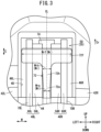
FIG. 3 is a partial rear view of the disc brake device. -
FIG. 4 is a partial rear view of the disc brake device. -
FIG. 5 is a cross-sectional view taken along line V-V ofFIG. 2 . - As shown in
FIG. 1 , adisc brake device 10 according to the present embodiment is mounted on a vehicle, as a brake device for a wheel.FIG. 1 shows, as an example, a case where thedisc brake device 10 is applied to a brake device for afront wheel 14 of a two-wheeled vehicle 12. In addition, in the description of the present embodiment, a front and rear direction, a left and right direction, and an up and down direction will be described, with a traveling direction of the two-wheeled vehicle 12 (a right direction inFIG. 1 ) being defined as a front direction. Thedisc brake device 10 is not limited to the example inFIG. 1 . Thedisc brake device 10 is provided on a wheel (thefront wheel 14 or rear wheel) of various vehicles such as a one-wheeled vehicle, a three-wheeled vehicle, and a four-wheeled vehicle. - In the following description, elements on a left side among elements of the
disc brake device 10 may be described with a letter "L" following a reference numeral. In addition, elements on a right side may be described with a letter "R" following a reference numeral. Further, elements on a front side may be described with a letter "F" following a reference numeral. Furthermore, elements on a rear side may be described with a letter "B" following a reference numeral. - The
disc brake device 10 includes abrake disc 16. Thebrake disc 16 is an annular plate-shaped member made of metal. Thebrake disc 16 is provided on the right side of thefront wheel 14. Thebrake disc 16 is connected to thefront wheel 14 so as to be substantially coaxial with anaxle 22 of thefront wheel 14. Therefore, thebrake disc 16 rotates integrally with thefront wheel 14. In addition, thedisc brake device 10 further includes abrake caliper 20. Thebrake caliper 20 is attached to afront fork 18 on the right side of thefront wheel 14. Anaxle support portion 24 is provided at a distal end portion of thefront fork 18. Theaxle support portion 24 pivotally supports theaxle 22. Abracket 26 extending to a right rear side of thefront wheel 14 is connected to theaxle support portion 24. As shown inFIGS. 1 to 5 , thebrake caliper 20 is supported by thebracket 26 so as to straddle thebrake disc 16. - In
FIGS. 1 to 5 , a double-headed arrow of C indicates a circumferential direction of thefront wheel 14 and thebrake disc 16. In addition, an arrow of Cr indicates a rotation direction of thefront wheel 14 and thebrake disc 16. One end portion side (one end portion side in a rotational direction Cr) of thebrake caliper 20 is referred to as a disc rotation-inside 28. The other end portion side (the other end portion side in the rotational direction Cr) of thebrake caliper 20 is referred to as a disc rotation-outside 30. The disc rotation-inside 28 is a side (inlet side) on which thebrake disc 16 enters thebrake caliper 20 during forward movement of the two-wheeledvehicle 12. That is, when thefront wheel 14 rotates during the forward movement of the two-wheeledvehicle 12, thebrake disc 16 enters the disc rotation-inside 28. The disc rotation-outside 30 is a side (outlet side) on which thebrake disc 16 comes out from thebrake caliper 20 during the forward movement of the two-wheeledvehicle 12. That is, when thefront wheel 14 rotates during the forward movement of the two-wheeledvehicle 12, thebrake disc 16 comes out from the disc rotation-outside 30. - The
brake caliper 20 is supported by thebracket 26 on the right rear side of thefront wheel 14. Thebrake caliper 20 extends substantially in a vertical direction along thebrake disc 16. Since thebrake caliper 20 is located near a rear part of thefront wheel 14, a lower side of thebrake caliper 20 is the disc rotation-inside 28. In addition, an upper side of thebrake caliper 20 is the disc rotation-outside 30. For example, when thebrake caliper 20 is disposed on a right front side of thefront wheel 14, the lower side of thebrake caliper 20 is the disc rotation-outside 30. In addition, in this case, the upper side of thebrake caliper 20 is the disc rotation-inside 28. In the following description, a case where thebrake caliper 20 is disposed as shown inFIGS. 1 ,2 , and5 will be described. - As shown in
FIGS. 1 to 5 , thebrake caliper 20 includes a pair of actingportions bridge portion 34B, and theother bridge portion 34F. As shown inFIG. 2 , thebrake disc 16 is disposed on a center line CL of thebrake caliper 20. The pair of actingportions brake disc 16 interposed therebetween. The onebridge portion 34B connects the pair of actingportions brake disc 16. The onebridge portion 34B connects the pair of actingportions side 28. Theother bridge portion 34F connects the pair of actingportions brake disc 16. Theother bridge portion 34F connects the pair of actingportions side 30. - The pair of acting
portions brake disc 16. Therefore, thebrake disc 16 enters agap 35 between the pair of actingportions brake disc 16 rotates in the rotation direction Cr at an intermediate position in a left-right direction of thegap 35. The left-right direction of thegap 35 is also an axial direction of thebrake disc 16, an axial direction of thefront wheel 14, and a vehicle width direction of the two-wheeledvehicle 12. In addition, the intermediate position is located on the center line CL of thebrake caliper 20. - Insertion holes 36B, 36F are formed in the disc rotation-in
side 28 and the disc rotation-outside 30 of the actingportion 32R on the right side, respectively. The actingportion 32R on the right side is fixed to thebracket 26 by two attachment bolts (not shown) inserted through the insertion holes 36B, 36F. - The
bridge portions portions brake disc 16. In addition, thebridge portions portions FIGS. 2 to 5 , the pair of actingportions bridge portions opening 40 that opens rearward. - As shown in
FIGS. 2 ,3 , and5 , protrudingportions portions portions portions portions bridge portions hanger pin 44 extending in the left-right direction penetrates the two protrudingportions - As shown in
FIGS. 2 to 5 , thedisc brake device 10 further includes a plurality ofpistons brake pads pistons brake pads brake caliper 20. That is, thegap 35 between the pair of actingportions pad accommodation chamber 50. The pair ofbrake pads pad accommodation chamber 50. The plurality ofpistons portions - Specifically, two cylinder holes (not shown) are formed in the acting
portion 32L on the left side. The two cylinder holes extend in the left-right direction. The two cylinder holes open toward thebrake disc 16. One of the cylinder holes is formed between the protrudingportion 42L and the onebridge portion 34B. The other cylinder hole is formed between the protrudingportion 42L and theother bridge portion 34F. That is, the two cylinder holes are respectively formed on a front side and a rear side of the actingportion 32L on the left side. Thepistons 46L are respectively accommodated in the cylinder holes. A hydraulic chamber (not shown) is formed between the cylinder hole and thepiston 46L. - Similarly, the two cylinder holes (not shown) are formed in the acting
portion 32R on the right side. The two cylinder holes extend in the left-right direction. The two cylinder holes open toward thebrake disc 16. One of the cylinder holes is formed between the protrudingportion 42R and the onebridge portion 34B. The other cylinder hole is formed between the protrudingportion 42R and theother bridge portion 34F. That is, the two cylinder holes are respectively formed on a front side and a rear side of the actingportion 32R on the right side. Thepistons 46R are respectively accommodated in the cylinder holes. The hydraulic chamber (not shown) is formed between the cylinder hole and thepiston 46R. - Accordingly, the
brake caliper 20 is a four-pot caliper of an opposing piston type. The pair ofbrake pads brake disc 16 due to action of thepistons pistons brake caliper 20 may be any number. - The brake
pad accommodation chamber 50 is formed by inner surfaces of the pair of actingportions brake disc 16 side, inner surfaces of the twobridge portions bottom portion 56 of thebrake caliper 20 on the inner side in the radial direction of thebrake disc 16. The inner surfaces of the twobridge portions bottom portion 56 of thebrake caliper 20 is a portion extending from bottom portions of the pair of actingportions portions brake disc 16. - The pair of
brake pads friction members rear plates friction members brake disc 16. Each of thefriction members friction members brake disc 16. Therear plates friction members rear plates rear plates friction members rear plates pistons - The bottom surface (surface on an inner side in the radial direction) of each of the
rear plates bottom portion 56 of thebrake caliper 20. In addition, the side surface of each of therear plates side 28 is contactable with the inner surface of the onebridge portion 34B. Further, the side surface of each of therear plates side 30 is contactable with the inner surface of theother bridge portion 34F. - A plurality of protruding
portions rear plates FIG. 5 ). The plurality of protrudingportions rear plates portions portions friction members FIGS. 2 ,3 , and5 , the protrudingportions rear plates portions portions portions hanger pin 44 penetrates each of the protrudingportions - Specifically, the protruding
portions rear plates side 28. The protrudingportions rear plates brake disc 16. Each of the protrudingportions bridge portion 34B. - In addition, the protruding
portions 64L, 64R are located at the ends of therear plates side 30. The protrudingportions 64L, 64R protrude from the rear surfaces of therear plates brake disc 16. Each of the protrudingportions 64L, 64R is contactable with the inner surface of theother bridge portion 34F. - Further, the protruding portions 66L, 66R are located on the disc rotation-in side 28 (on an upstream side in the circumferential direction C and the rotational direction Cr) with respect to the protruding
portions rear plates rear plates brake disc 16. A protruding amount of each of the protruding portions 66L, 66R outward in the radial direction of thebrake disc 16 is smaller than a protruding amount of each of the protrudingportions brake disc 16. In addition, distal end surfaces (rear surfaces on the outer side in the radial direction) of the protruding portions 66L, 66R are inclined toward distal ends of the protrudingportions - Furthermore, the protruding
portions 68L, 68R are located on the disc rotation-out side 30 (on a downstream side in the circumferential direction C and the rotational direction Cr) with respect to the protrudingportions rear plates portions 68L, 68R protrude from the rear surfaces of therear plates brake disc 16. A protruding amount of each of the protrudingportions 68L, 68R outward in the radial direction of thebrake disc 16 is smaller than a protruding amount of each of the protrudingportions brake disc 16. In addition, distal end surfaces (rear surfaces on the outer side in the radial direction) of the protrudingportions 68L, 68R are inclined toward distal ends of the protrudingportions - Accordingly, the pair of
brake pads rear plates portions bridge portions brake pads rear plates bottom portion 56 of thebrake caliper 20. In addition, therear plates hanger pin 44. Accordingly, the pair ofbrake pads brake disc 16. Accordingly, the pair ofbrake pads pad accommodation chamber 50. - As shown in
FIGS. 1 to 5 , thebrake caliper 20 further includes aretainer 72. Theretainer 72 elastically biases the pair ofbrake pads brake pads bottom portion 56 of thebrake caliper 20 by a biasing force from theretainer 72. Theretainer 72 is a plate spring member (pad spring) extending along the circumferential direction C. Theretainer 72 covers agap 74 between thefriction members brake disc 16. Here, a width of theretainer 72 in the left-right direction (a width in the axial direction W which is a direction orthogonal to the center line CL) is denoted by Wr. In addition, in the following description, a width of each portion of theretainer 72 in the axial direction W may be described by adding lowercase alphabets following Wr. - The
retainer 72 has an arc-shapedportion 72a. The arc-shapedportion 72a is locked to a central portion of thehanger pin 44. Thehanger pin 44 locks the arc-shapedportion 72a at a portion of thehanger pin 44 on the inner side in the radial direction of thebrake disc 16. The following elements are sequentially connected to a portion of the arc-shapedportion 72a on the disc rotation-inside 28. - An
abutment portion 72b is connected to the arc-shapedportion 72a. Theabutment portion 72b is located on the disc rotation-inside 28 with respect to the arc-shapedportion 72a. Theabutment portion 72b is a widened portion (width Wrb) that is curved and abuts against the protruding portions 66L, 66R of therear plates - A
connection portion 72c is connected to theabutment portion 72b. Theconnection portion 72c is located on the disc rotation-inside 28 with respect to theabutment portion 72b. Theconnection portion 72c is formed in a flat plate shape. A width of theconnection portion 72c is narrower than the width Wrb of theabutment portion 72b. Specifically, a portion of theconnection portion 72c on the disc rotation-outside 30 is connected to theabutment portion 72b. The connection portion is a relatively widerwidened portion 72g of theconnection portion 72c. A width Wrc1 of the widenedportion 72g is narrower than the width Wrb of theabutment portion 72b (Wrc1 < Wrb). In addition, a width Wrc2 of a portion of theconnection portion 72c on the disc rotation-inside 28 is narrower than the width Wrc1 of the widenedportion 72g (Wrc2 < Wrc1). - A rotation-in
side end portion 72d is connected to theconnection portion 72c. The rotation-inside end portion 72d is located on the disc rotation-inside 28 with respect to theconnection portion 72c. A width Wrd of the rotation-inside end portion 72d is the width Wrd substantially the same as that of the portion of theconnection portion 72c on the disc rotation-in side 28 (Wrc2 ≈ Wrd). A recessedportion 76 is formed in a central portion (a central portion in the axial direction W) of the inner surface of the onebridge portion 34B. The rotation-inside end portion 72d is locked to the recessedportion 76. - The following elements are sequentially connected to a portion of the arc-shaped
portion 72a on the disc rotation-outside 30. - A
connection portion 72e is connected to the arc-shapedportion 72a. Theconnection portion 72e is located on the disc rotation-outside 30 with respect to the arc-shapedportion 72a. Theconnection portion 72e is formed in a flat plate shape. A width Wre of theconnection portion 72e is a width substantially the same as that of the arc-shapedportion 72a. Anabutment portion 72f is connected to theconnection portion 72e. Theabutment portion 72f is located on the disc rotation-outside 30 with respect to theconnection portion 72e. Theabutment portion 72f is a widened portion that abuts against the protrudingportions 64L, 64R of therear plates abutment portion 72f is a rotation-out side end portion of theretainer 72. A width Wrf of theabutment portion 72f is substantially the same as the width Wrb of theabutment portion 72b (Wrf ≈ Wrb > Wre). - The
abutment portion 72b of theretainer 72 abuts against the protruding portions 66L, 66R of therear plates abutment portion 72f of theretainer 72 abuts against the protrudingportions 64L, 64R of therear plates brake pads brake disc 16. In addition, the pair ofbrake pads side 30. As a result, even if there is some backlash between the pair ofbrake pads brake caliper 20, the pair ofbrake pads pad accommodation chamber 50 can be held by thebrake caliper 20. - When a driver of the two-wheeled
vehicle 12 operates a brake lever (not shown) in a state where thefront wheel 14 rotates in the rotation direction Cr, thepistons brake disc 16 side). When thepistons rear plates brake pads friction members rear plates brake disc 16. As a result, thebrake disc 16 and thefront wheel 14 are braked by the pair ofbrake pads - In this case, the pair of
brake pads brake disc 16. Accordingly, the protrudingportions 64R, 64L of therear plates bridge portion 34F. Therefore, the inner surface of thebridge portion 34F functions as a receiving surface for receiving a torque acting on the pair ofbrake pads - As shown in
FIG. 2 , each of theconnection portions connection portions retainer 72 to change a load at the stress concentration portions in theconnection portions connection portions disc brake device 10 according to the present embodiment, the stress concentration is dispersed at low cost without changing the plate thickness, the material, and the like of theretainer 72. Therefore, in thedisc brake device 10, the following characteristic configuration is adopted with respect to a structure of theretainer 72. - That is, as shown in
FIGS. 2 to 4 , the twoconnection portions abutment portions portions portions abutment portions portions connection portions portions connection portions - Specifically, a portion of the
connection portion 72c that is connected to theabutment portion 72b (a portion having the width Wrc1) is the widenedportion 72g. - In addition, a portion of the
connection portion 72e that is connected to theabutment portion 72f is formed in a tapered shape that gradually increases in width toward theabutment portion 72f. The taper-shaped portion (the portion connected to theabutment portion 72f) is the widenedportion 72h having a width Wrh (Wrh > Wre). - Accordingly, the
connection portion 72c is connected to theabutment portion 72b. In this case, the widenedportion 72g is formed adjacent to theabutment portion 72b at theconnection portion 72c. On the other hand, theconnection portion 72e is connected to theabutment portion 72f. In this case, the widenedportion 72h is formed adjacent to theabutment portion 72f at theconnection portion 72e. - In addition, in the
retainer 72, the plurality ofabutment portions connection portions abutment portions portion 72g of theconnection portion 72c is wider in the left-right direction (the axial direction W) than the width Wrh of the widenedportion 72h of theconnection portion 72e (Wrc1 > Wrh). - Moreover, any
mark 80 is provided on a surface on the outer side in the radial direction of the wider widenedportion 72g. InFIGS. 2 and4 , as an example, an arrow and a letter "UP" that indicate an assembling direction of theretainer 72 with respect to thebrake caliper 20 are provided. - The invention that can be understood from the above embodiment will be described below.
- A disc brake device (10) includes: a brake disc (16); a brake caliper (20) provided to straddle the brake disc (16); a pair of brake pads (48L, 48R) accommodated in the brake caliper (20) and configured to clamp the brake disc (16); and a retainer (72) provided for the brake caliper (20) and configured to abut against the pair of brake pads (48L, 48R) in order to cause the pair of brake pads (48L, 48R) to be held by the brake caliper (20). The retainer (72) includes: an abutment portion (72b, 72f) configured to press the pair of brake pads (48L, 48R) inward in a radial direction of the brake disc (16) by abutting against the pair of brake pads (48L, 48R); a connection portion (72c, 72e) connected to the abutment portion (72b, 72f); and a widened portion (72g, 72h) provided in the connection portion (72c, 72e) and configured to alleviate stress concentration at the connection portion (72c, 72e) by being formed to be wider in an axial direction (W) of the brake disc (16) than other portion in the connection portion (72c, 72e) .
- According to this configuration, by providing the widened portion in the connection portion, the load at the stress concentration portion in the connection portions can be changed to disperse the stress concentration without changing a plate thickness, a material, or the like of the retainer and without increasing the cost.
- When an inlet side of the brake caliper (20) in a rotation direction (Cr) of the brake disc (16) is a disc rotation-in side (28) and an outlet side of the brake caliper (20) in the rotation direction (Cr) is a disc rotation-out side (30), the abutment portion (72b, 72f) is provided to press the pair of brake pads (48L, 48R) inward in the radial direction and toward the disc rotation-out side (30). The connection portion (72c, 72e) is connected to the disc rotation-in side (28) of the abutment portion (72b, 72f), and the widened portion (72g, 72h) is formed adjacent to the abutment portion (72b, 72f) at the connection portion (72c, 72e).
- According to this configuration, the widened portion is formed adjacent to the abutment portion. Accordingly, when the pair of brake pads are pressed by the abutment portions inward in the radial direction and toward the disc rotation-out side, generation of abnormal noise such as "squeal" generated in sliding portions between the pair of brake pads and the brake disc and generation of uneven wear at the pair of brake pads are prevented. In addition, the stress concentration can also be dispersed.
- The retainer (72) includes a plurality of the abutment portions (72b, 72f) provided at any interval in the rotation direction (Cr), and a plurality of the connection portions (72c, 72e) connected to the plurality of the abutment portions (72b, 72f) in the rotation direction (Cr) and provided with the widened portions (72g, 72h). The widened portion (72g) on the disc rotation-in side (28) of the plurality of widened portions (72g, 72h) is wider in the axial direction (W) than the widened portion (72h) on the disc rotation-out side (30).
- According to this configuration, the plurality of abutment portions are connected by the plurality of connection portions, and the widened portions are formed in the plurality of connection portions, respectively. Accordingly, when the pair of brake pads are pressed inward in the radial direction and toward the disc rotation-out side by the plurality of abutment portions, stresses of different magnitudes generated in the plurality of connection portions can be efficiently dispersed.
- In addition, the abutment portion on the disc rotation-in side presses the pair of brake pads from the disc rotation-in side toward the disc rotation-out side. Therefore, the connection portion connected to the disc rotation-in side with respect to the abutment portion on the disc rotation-in side has a larger stress concentration than the other connection portions. Therefore, in this configuration, a width in the axial direction of the widened portion on the disc rotation-in side is made wider than a width in the axial direction of the widened portion on the disc rotation-out side. Accordingly, it is possible to effectively disperse the stress concentration generated in the connection portion on the disc rotation-in side.
- The widened portion (72g, 72h) is provided with any mark (80).
- According to this configuration, it is possible to suitably provide a mark such as an assembling direction of the retainer with respect to the brake caliper.
- The invention is not limited to the embodiments described above, and various configurations can be adopted without departing from the gist of the invention.
Claims (4)
- A disc brake device (10) comprising:a brake disc (16);a brake caliper (20) provided to straddle the brake disc (16);a pair of brake pads (48L, 48R) accommodated in the brake caliper (20) and configured to clamp the brake disc (16); anda retainer (72) provided for the brake caliper (20) and configured to abut against the pair of brake pads (48L, 48R) in order to cause the pair of brake pads (48L, 48R) to be held by the brake caliper (20), whereinthe retainer (72) includes:an abutment portion (72b, 72f) configured to press the pair of brake pads (48L, 48R) inward in a radial direction of the brake disc (16) by abutting against the pair of brake pads (48L, 48R);a connection portion (72c, 72e) connected to the abutment portion (72b, 72f); anda widened portion (72g, 72h) provided in the connection portion (72c, 72e) and configured to alleviate stress concentration at the connection portion (72c, 72e) by being formed to be wider in an axial direction (W) of the brake disc (16) than other portion in the connection portion (72c, 72e).
- The disc brake device (10) according to claim 1, whereinwhen an inlet side of the brake caliper (20) in a rotation direction (Cr) of the brake disc (16) is a disc rotation-in side (28) and an outlet side of the brake caliper (20) in the rotation direction (Cr) is a disc rotation-out side (30), the abutment portion (72b, 72f) is provided to press the pair of brake pads (48L, 48R) inward in the radial direction and toward the disc rotation-out side (30),the connection portion (72c, 72e) is connected to the disc rotation-in side (28) of the abutment portion (72b, 72f), andthe widened portion (72g, 72h) is formed adjacent to the abutment portion (72b, 72f) at the connection portion (72c, 72e).
- The disc brake device (10) according to claim 2, whereinthe retainer (72) includes a plurality of the abutment portions (72b, 72f) provided at any interval in the rotation direction (Cr), and a plurality of the connection portions (72c, 72e) connected to the plurality of the abutment portions (72b, 72f) in the rotation direction (Cr) and provided with the widened portions (72g, 72h), andthe widened portion (72g) on the disc rotation-in side (28) of the plurality of widened portions (72g, 72h) is wider in the axial direction (W) than the widened portion (72h) on the disc rotation-out side (30).
- The disc brake device (10) according to any one of claims 1 to 3, wherein
the widened portion (72g, 72h) is provided with any mark (80).
Applications Claiming Priority (2)
| Application Number | Priority Date | Filing Date | Title |
|---|---|---|---|
| JP2020141377 | 2020-08-25 | ||
| PCT/JP2021/030924 WO2022045107A1 (en) | 2020-08-25 | 2021-08-24 | Disc brake device |
Publications (2)
| Publication Number | Publication Date |
|---|---|
| EP4206486A1 true EP4206486A1 (en) | 2023-07-05 |
| EP4206486A4 EP4206486A4 (en) | 2024-09-25 |
Family
ID=80353334
Family Applications (1)
| Application Number | Title | Priority Date | Filing Date |
|---|---|---|---|
| EP21861532.6A Pending EP4206486A4 (en) | 2020-08-25 | 2021-08-24 | DISC BRAKE DEVICE |
Country Status (4)
| Country | Link |
|---|---|
| EP (1) | EP4206486A4 (en) |
| JP (1) | JP7768884B2 (en) |
| CN (1) | CN115956170B (en) |
| WO (1) | WO2022045107A1 (en) |
Family Cites Families (20)
| Publication number | Priority date | Publication date | Assignee | Title |
|---|---|---|---|---|
| DE2225178A1 (en) * | 1972-05-24 | 1974-01-17 | Teves Gmbh Alfred | PARTIAL DISC BRAKE |
| DE4442795A1 (en) * | 1994-12-01 | 1996-06-05 | Teves Gmbh Alfred | Anti=rattle spring for brake discs |
| DE4442796A1 (en) * | 1994-12-01 | 1996-06-05 | Teves Gmbh Alfred | Hold-down spring for disc brakes |
| JP3729583B2 (en) * | 1996-12-19 | 2005-12-21 | 日信工業株式会社 | Vehicle disc brake |
| DE19746572A1 (en) * | 1997-10-22 | 1999-04-29 | Itt Mfg Enterprises Inc | Noise dampening arrangement for motor vehicle brakes |
| DE69925848D1 (en) * | 1999-12-16 | 2005-07-21 | Freni Brembo Spa | Mounting bracket for brake pad holding pins |
| JP4055065B2 (en) * | 2002-08-29 | 2008-03-05 | 株式会社日立製作所 | Disc brake |
| JP4028347B2 (en) * | 2002-10-22 | 2007-12-26 | 株式会社日立製作所 | Disc brake |
| JP2004183904A (en) | 2004-03-29 | 2004-07-02 | Nissin Kogyo Co Ltd | Disc brakes for vehicles |
| JP2006097867A (en) * | 2004-09-30 | 2006-04-13 | Hitachi Ltd | Disc brake |
| JP4713417B2 (en) * | 2006-07-28 | 2011-06-29 | 日立オートモティブシステムズ株式会社 | Disc brake |
| JP2011163444A (en) * | 2010-02-09 | 2011-08-25 | Nissin Kogyo Co Ltd | Disk brake for vehicle |
| JP5512397B2 (en) * | 2010-05-31 | 2014-06-04 | 日立オートモティブシステムズ株式会社 | Disc brake |
| JP2012237375A (en) * | 2011-05-11 | 2012-12-06 | Nissin Kogyo Co Ltd | Disk brake for vehicle |
| BR112018010050B1 (en) * | 2015-11-26 | 2023-04-11 | Hitachi Astemo, Ltd | DISC BRAKE |
| ITUB20159344A1 (en) * | 2015-12-23 | 2017-06-23 | Freni Brembo Spa | LAMINA SPRING FOR BRAKE CALIPER AND CALIPER BODY INCLUDING THE SPRING |
| JP6686852B2 (en) * | 2016-11-18 | 2020-04-22 | 株式会社アドヴィックス | Disc brake with piston facing |
| JP6746789B2 (en) * | 2017-06-30 | 2020-08-26 | 日立オートモティブシステムズ株式会社 | Disc brake |
| JP7110049B2 (en) * | 2018-09-21 | 2022-08-01 | 曙ブレーキ工業株式会社 | Disc brake pad spring and disc brake device |
| JP2020046037A (en) * | 2018-09-21 | 2020-03-26 | 日信工業株式会社 | Disc brake for vehicle |
-
2021
- 2021-08-24 WO PCT/JP2021/030924 patent/WO2022045107A1/en not_active Ceased
- 2021-08-24 CN CN202180050749.5A patent/CN115956170B/en active Active
- 2021-08-24 JP JP2022544609A patent/JP7768884B2/en active Active
- 2021-08-24 EP EP21861532.6A patent/EP4206486A4/en active Pending
Also Published As
| Publication number | Publication date |
|---|---|
| EP4206486A4 (en) | 2024-09-25 |
| JPWO2022045107A1 (en) | 2022-03-03 |
| CN115956170A (en) | 2023-04-11 |
| JP7768884B2 (en) | 2025-11-12 |
| WO2022045107A1 (en) | 2022-03-03 |
| CN115956170B (en) | 2026-07-17 |
Similar Documents
| Publication | Publication Date | Title |
|---|---|---|
| TWI582321B (en) | Disc brake caliper and disc brake caliper assembly | |
| EP0994269B1 (en) | Disk brake assembly | |
| EP1122162B1 (en) | Disc brake assembly | |
| EP1122161B1 (en) | Bicycle disk brake | |
| US8651244B2 (en) | Hydraulic brake device | |
| TWI859625B (en) | Brake mounts for bicycles | |
| US7926625B2 (en) | Disk braking device and motorcycle provided with the disk braking device | |
| EP3436715A1 (en) | Disc brake caliper body | |
| US7845473B2 (en) | Brake caliper structure of straddle seat off-road vehicle | |
| TWI845080B (en) | Flat mount brake caliper for bicycle | |
| JP7768884B2 (en) | disc brake device | |
| JP7653444B2 (en) | Disc brake device | |
| US7849980B2 (en) | Disk braking device and motorcycle provided with the disk braking device | |
| US7275624B2 (en) | Disk brake unit for motorcycle | |
| JP7030102B2 (en) | Disc brake structure | |
| JP4139039B2 (en) | Caliper body mounting structure for vehicle disc brakes | |
| JP4818307B2 (en) | Disc brake for radial mount type vehicle | |
| JP2008261412A (en) | Drum brakes, brake linings, and saddle riding type vehicles | |
| US10837504B2 (en) | Brake caliper support element | |
| JPH0726582Y2 (en) | Disc brake | |
| CN111971227A (en) | Deceleration system | |
| JP2007245832A (en) | Front brake device for motorcycles | |
| JPH05248461A (en) | Disc brake device | |
| JPH08332987A (en) | Rear wheel axle support structure for motorcycles |
Legal Events
| Date | Code | Title | Description |
|---|---|---|---|
| STAA | Information on the status of an ep patent application or granted ep patent |
Free format text: STATUS: THE INTERNATIONAL PUBLICATION HAS BEEN MADE |
|
| PUAI | Public reference made under article 153(3) epc to a published international application that has entered the european phase |
Free format text: ORIGINAL CODE: 0009012 |
|
| STAA | Information on the status of an ep patent application or granted ep patent |
Free format text: STATUS: REQUEST FOR EXAMINATION WAS MADE |
|
| 17P | Request for examination filed |
Effective date: 20230323 |
|
| AK | Designated contracting states |
Kind code of ref document: A1 Designated state(s): AL AT BE BG CH CY CZ DE DK EE ES FI FR GB GR HR HU IE IS IT LI LT LU LV MC MK MT NL NO PL PT RO RS SE SI SK SM TR |
|
| DAV | Request for validation of the european patent (deleted) | ||
| DAX | Request for extension of the european patent (deleted) | ||
| A4 | Supplementary search report drawn up and despatched |
Effective date: 20240823 |
|
| RIC1 | Information provided on ipc code assigned before grant |
Ipc: F16D 55/228 20060101ALI20240819BHEP Ipc: F16D 65/097 20060101AFI20240819BHEP |
|
| RAP3 | Party data changed (applicant data changed or rights of an application transferred) |
Owner name: ASTEMO, LTD. |