EP4206442A1 - Turbocharger turbine assembly - Google Patents
Turbocharger turbine assembly Download PDFInfo
- Publication number
- EP4206442A1 EP4206442A1 EP22181605.1A EP22181605A EP4206442A1 EP 4206442 A1 EP4206442 A1 EP 4206442A1 EP 22181605 A EP22181605 A EP 22181605A EP 4206442 A1 EP4206442 A1 EP 4206442A1
- Authority
- EP
- European Patent Office
- Prior art keywords
- vanes
- nozzle
- turbine housing
- vane
- housing assembly
- Prior art date
- Legal status (The legal status is an assumption and is not a legal conclusion. Google has not performed a legal analysis and makes no representation as to the accuracy of the status listed.)
- Pending
Links
- 230000003247 decreasing effect Effects 0.000 claims abstract description 10
- 230000007704 transition Effects 0.000 claims description 23
- 125000006850 spacer group Chemical group 0.000 description 20
- 239000000463 material Substances 0.000 description 15
- 238000002485 combustion reaction Methods 0.000 description 14
- PXHVJJICTQNCMI-UHFFFAOYSA-N Nickel Chemical compound [Ni] PXHVJJICTQNCMI-UHFFFAOYSA-N 0.000 description 11
- 238000000429 assembly Methods 0.000 description 11
- 230000000712 assembly Effects 0.000 description 11
- 238000000034 method Methods 0.000 description 10
- 229910045601 alloy Inorganic materials 0.000 description 9
- 239000000956 alloy Substances 0.000 description 9
- 239000007789 gas Substances 0.000 description 7
- 239000000411 inducer Substances 0.000 description 7
- 230000007246 mechanism Effects 0.000 description 7
- 230000001052 transient effect Effects 0.000 description 6
- 229910052759 nickel Inorganic materials 0.000 description 5
- 238000013459 approach Methods 0.000 description 4
- 230000000694 effects Effects 0.000 description 4
- 239000000314 lubricant Substances 0.000 description 4
- XEEYBQQBJWHFJM-UHFFFAOYSA-N Iron Chemical compound [Fe] XEEYBQQBJWHFJM-UHFFFAOYSA-N 0.000 description 3
- 230000008859 change Effects 0.000 description 3
- 238000011161 development Methods 0.000 description 3
- 230000018109 developmental process Effects 0.000 description 3
- 239000000446 fuel Substances 0.000 description 3
- 238000003754 machining Methods 0.000 description 3
- 229910001220 stainless steel Inorganic materials 0.000 description 3
- 239000010935 stainless steel Substances 0.000 description 3
- 230000003068 static effect Effects 0.000 description 3
- 230000004323 axial length Effects 0.000 description 2
- 239000011651 chromium Substances 0.000 description 2
- 238000010276 construction Methods 0.000 description 2
- 230000008602 contraction Effects 0.000 description 2
- 238000001816 cooling Methods 0.000 description 2
- 239000002283 diesel fuel Substances 0.000 description 2
- 230000003292 diminished effect Effects 0.000 description 2
- 230000005484 gravity Effects 0.000 description 2
- 229910000816 inconels 718 Inorganic materials 0.000 description 2
- 230000003993 interaction Effects 0.000 description 2
- 230000008569 process Effects 0.000 description 2
- 230000009467 reduction Effects 0.000 description 2
- 238000005096 rolling process Methods 0.000 description 2
- 229910001256 stainless steel alloy Inorganic materials 0.000 description 2
- 238000011144 upstream manufacturing Methods 0.000 description 2
- VYZAMTAEIAYCRO-UHFFFAOYSA-N Chromium Chemical compound [Cr] VYZAMTAEIAYCRO-UHFFFAOYSA-N 0.000 description 1
- 229910000990 Ni alloy Inorganic materials 0.000 description 1
- 238000003483 aging Methods 0.000 description 1
- UQZIWOQVLUASCR-UHFFFAOYSA-N alumane;titanium Chemical compound [AlH3].[Ti] UQZIWOQVLUASCR-UHFFFAOYSA-N 0.000 description 1
- 230000004888 barrier function Effects 0.000 description 1
- 230000003197 catalytic effect Effects 0.000 description 1
- 238000006243 chemical reaction Methods 0.000 description 1
- 229910052804 chromium Inorganic materials 0.000 description 1
- BIJOYKCOMBZXAE-UHFFFAOYSA-N chromium iron nickel Chemical compound [Cr].[Fe].[Ni] BIJOYKCOMBZXAE-UHFFFAOYSA-N 0.000 description 1
- 239000000567 combustion gas Substances 0.000 description 1
- 238000004891 communication Methods 0.000 description 1
- 230000008021 deposition Effects 0.000 description 1
- 238000013461 design Methods 0.000 description 1
- 230000001627 detrimental effect Effects 0.000 description 1
- 238000010586 diagram Methods 0.000 description 1
- 238000009826 distribution Methods 0.000 description 1
- 238000005265 energy consumption Methods 0.000 description 1
- 238000005516 engineering process Methods 0.000 description 1
- 230000007613 environmental effect Effects 0.000 description 1
- 230000005284 excitation Effects 0.000 description 1
- 238000007667 floating Methods 0.000 description 1
- 239000012530 fluid Substances 0.000 description 1
- 238000010438 heat treatment Methods 0.000 description 1
- 229910001119 inconels 625 Inorganic materials 0.000 description 1
- 238000009434 installation Methods 0.000 description 1
- 229910052742 iron Inorganic materials 0.000 description 1
- 235000000396 iron Nutrition 0.000 description 1
- 229910052751 metal Inorganic materials 0.000 description 1
- 239000002184 metal Substances 0.000 description 1
- 238000012986 modification Methods 0.000 description 1
- 230000004048 modification Effects 0.000 description 1
- 238000003825 pressing Methods 0.000 description 1
- 230000008707 rearrangement Effects 0.000 description 1
- 229910001088 rené 41 Inorganic materials 0.000 description 1
- 238000007789 sealing Methods 0.000 description 1
- 230000035939 shock Effects 0.000 description 1
- 239000004071 soot Substances 0.000 description 1
- 230000000087 stabilizing effect Effects 0.000 description 1
- 238000006467 substitution reaction Methods 0.000 description 1
- 229910001247 waspaloy Inorganic materials 0.000 description 1
Images


Classifications
-
- F—MECHANICAL ENGINEERING; LIGHTING; HEATING; WEAPONS; BLASTING
- F01—MACHINES OR ENGINES IN GENERAL; ENGINE PLANTS IN GENERAL; STEAM ENGINES
- F01D—NON-POSITIVE DISPLACEMENT MACHINES OR ENGINES, e.g. STEAM TURBINES
- F01D9/00—Stators
- F01D9/02—Nozzles; Nozzle boxes; Stator blades; Guide conduits, e.g. individual nozzles
- F01D9/04—Nozzles; Nozzle boxes; Stator blades; Guide conduits, e.g. individual nozzles forming ring or sector
- F01D9/047—Nozzle boxes
-
- F—MECHANICAL ENGINEERING; LIGHTING; HEATING; WEAPONS; BLASTING
- F02—COMBUSTION ENGINES; HOT-GAS OR COMBUSTION-PRODUCT ENGINE PLANTS
- F02B—INTERNAL-COMBUSTION PISTON ENGINES; COMBUSTION ENGINES IN GENERAL
- F02B37/00—Engines characterised by provision of pumps driven at least for part of the time by exhaust
- F02B37/12—Control of the pumps
- F02B37/24—Control of the pumps by using pumps or turbines with adjustable guide vanes
-
- F—MECHANICAL ENGINEERING; LIGHTING; HEATING; WEAPONS; BLASTING
- F01—MACHINES OR ENGINES IN GENERAL; ENGINE PLANTS IN GENERAL; STEAM ENGINES
- F01D—NON-POSITIVE DISPLACEMENT MACHINES OR ENGINES, e.g. STEAM TURBINES
- F01D17/00—Regulating or controlling by varying flow
- F01D17/10—Final actuators
- F01D17/12—Final actuators arranged in stator parts
- F01D17/14—Final actuators arranged in stator parts varying effective cross-sectional area of nozzles or guide conduits
- F01D17/16—Final actuators arranged in stator parts varying effective cross-sectional area of nozzles or guide conduits by means of nozzle vanes
- F01D17/165—Final actuators arranged in stator parts varying effective cross-sectional area of nozzles or guide conduits by means of nozzle vanes for radial flow, i.e. the vanes turning around axes which are essentially parallel to the rotor centre line
-
- F—MECHANICAL ENGINEERING; LIGHTING; HEATING; WEAPONS; BLASTING
- F01—MACHINES OR ENGINES IN GENERAL; ENGINE PLANTS IN GENERAL; STEAM ENGINES
- F01D—NON-POSITIVE DISPLACEMENT MACHINES OR ENGINES, e.g. STEAM TURBINES
- F01D25/00—Component parts, details, or accessories, not provided for in, or of interest apart from, other groups
- F01D25/24—Casings; Casing parts, e.g. diaphragms, casing fastenings
-
- F—MECHANICAL ENGINEERING; LIGHTING; HEATING; WEAPONS; BLASTING
- F02—COMBUSTION ENGINES; HOT-GAS OR COMBUSTION-PRODUCT ENGINE PLANTS
- F02B—INTERNAL-COMBUSTION PISTON ENGINES; COMBUSTION ENGINES IN GENERAL
- F02B37/00—Engines characterised by provision of pumps driven at least for part of the time by exhaust
- F02B37/12—Control of the pumps
- F02B37/22—Control of the pumps by varying cross-section of exhaust passages or air passages, e.g. by throttling turbine inlets or outlets or by varying effective number of guide conduits
- F02B37/225—Control of the pumps by varying cross-section of exhaust passages or air passages, e.g. by throttling turbine inlets or outlets or by varying effective number of guide conduits air passages
-
- F—MECHANICAL ENGINEERING; LIGHTING; HEATING; WEAPONS; BLASTING
- F02—COMBUSTION ENGINES; HOT-GAS OR COMBUSTION-PRODUCT ENGINE PLANTS
- F02C—GAS-TURBINE PLANTS; AIR INTAKES FOR JET-PROPULSION PLANTS; CONTROLLING FUEL SUPPLY IN AIR-BREATHING JET-PROPULSION PLANTS
- F02C6/00—Plural gas-turbine plants; Combinations of gas-turbine plants with other apparatus; Adaptations of gas-turbine plants for special use
- F02C6/04—Gas-turbine plants providing heated or pressurised working fluid for other apparatus, e.g. without mechanical power output
- F02C6/10—Gas-turbine plants providing heated or pressurised working fluid for other apparatus, e.g. without mechanical power output supplying working fluid to a user, e.g. a chemical process, which returns working fluid to a turbine of the plant
- F02C6/12—Turbochargers, i.e. plants for augmenting mechanical power output of internal-combustion piston engines by increase of charge pressure
-
- F—MECHANICAL ENGINEERING; LIGHTING; HEATING; WEAPONS; BLASTING
- F05—INDEXING SCHEMES RELATING TO ENGINES OR PUMPS IN VARIOUS SUBCLASSES OF CLASSES F01-F04
- F05D—INDEXING SCHEME FOR ASPECTS RELATING TO NON-POSITIVE-DISPLACEMENT MACHINES OR ENGINES, GAS-TURBINES OR JET-PROPULSION PLANTS
- F05D2220/00—Application
- F05D2220/40—Application in turbochargers
-
- F—MECHANICAL ENGINEERING; LIGHTING; HEATING; WEAPONS; BLASTING
- F05—INDEXING SCHEMES RELATING TO ENGINES OR PUMPS IN VARIOUS SUBCLASSES OF CLASSES F01-F04
- F05D—INDEXING SCHEME FOR ASPECTS RELATING TO NON-POSITIVE-DISPLACEMENT MACHINES OR ENGINES, GAS-TURBINES OR JET-PROPULSION PLANTS
- F05D2240/00—Components
- F05D2240/10—Stators
- F05D2240/14—Casings or housings protecting or supporting assemblies within
-
- F—MECHANICAL ENGINEERING; LIGHTING; HEATING; WEAPONS; BLASTING
- F05—INDEXING SCHEMES RELATING TO ENGINES OR PUMPS IN VARIOUS SUBCLASSES OF CLASSES F01-F04
- F05D—INDEXING SCHEME FOR ASPECTS RELATING TO NON-POSITIVE-DISPLACEMENT MACHINES OR ENGINES, GAS-TURBINES OR JET-PROPULSION PLANTS
- F05D2240/00—Components
- F05D2240/55—Seals
-
- F—MECHANICAL ENGINEERING; LIGHTING; HEATING; WEAPONS; BLASTING
- F05—INDEXING SCHEMES RELATING TO ENGINES OR PUMPS IN VARIOUS SUBCLASSES OF CLASSES F01-F04
- F05D—INDEXING SCHEME FOR ASPECTS RELATING TO NON-POSITIVE-DISPLACEMENT MACHINES OR ENGINES, GAS-TURBINES OR JET-PROPULSION PLANTS
- F05D2250/00—Geometry
- F05D2250/10—Two-dimensional
- F05D2250/19—Two-dimensional machined; miscellaneous
- F05D2250/192—Two-dimensional machined; miscellaneous bevelled
-
- F—MECHANICAL ENGINEERING; LIGHTING; HEATING; WEAPONS; BLASTING
- F05—INDEXING SCHEMES RELATING TO ENGINES OR PUMPS IN VARIOUS SUBCLASSES OF CLASSES F01-F04
- F05D—INDEXING SCHEME FOR ASPECTS RELATING TO NON-POSITIVE-DISPLACEMENT MACHINES OR ENGINES, GAS-TURBINES OR JET-PROPULSION PLANTS
- F05D2250/00—Geometry
- F05D2250/70—Shape
Definitions
- Subject matter disclosed herein relates generally to turbochargers for internal combustion engines.
- Exhaust driven turbochargers include a rotating group that includes a turbine wheel and a compressor wheel that are connected to one another by a shaft.
- the shaft is typically rotatably supported within a center housing by one or more bearings.
- exhaust from an internal combustion engine drives a turbocharger's turbine wheel, which, in turn, drives the compressor wheel to boost charge air to the internal combustion engine.
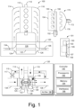
- a system 100 can include an internal combustion engine 110 and a turbocharger 120. As shown in Fig. 1 , the system 100 may be part of a vehicle 101 where the system 100 is disposed in an engine compartment and connected to an exhaust conduit 103 that directs exhaust to an exhaust outlet 109, for example, located behind a passenger compartment 105. In the example of Fig. 1 , a treatment unit 107 may be provided to treat exhaust (e.g., to reduce emissions via catalytic conversion of molecules, etc.).
- the internal combustion engine 110 includes an engine block 118 housing one or more combustion chambers that operatively drive a shaft 112 (e.g., via pistons) as well as an intake port 114 that provides a flow path for air to the engine block 118 and an exhaust port 116 that provides a flow path for exhaust from the engine block 118.
- the turbocharger 120 can act to extract energy from the exhaust and to provide energy to intake air, which may be combined with fuel to form combustion gas.
- the turbocharger 120 includes an air inlet 134, a shaft 122, a compressor housing assembly 124 for a compressor wheel 125, a turbine housing assembly 126 for a turbine wheel 127, another housing assembly 128 and an exhaust outlet 136.
- the housing assembly 128 may be referred to as a center housing assembly as it is disposed between the compressor housing assembly 124 and the turbine housing assembly 126.
- the shaft 122 may be a shaft assembly that includes a variety of components (e.g., consider a shaft and wheel assembly (SWA) where the turbine wheel 127 is welded to the shaft 122, etc.).
- the shaft 122 may be rotatably supported by a bearing system (e.g., journal bearing(s), rolling element bearing(s), etc.) disposed in the housing assembly 128 (e.g., in a bore defined by one or more bore walls) such that rotation of the turbine wheel 127 causes rotation of the compressor wheel 125 (e.g., as rotatably coupled by the shaft 122).
- a bearing system e.g., journal bearing(s), rolling element bearing(s), etc.
- the housing assembly 128 e.g., in a bore defined by one or more bore walls
- a center housing rotating assembly can include the compressor wheel 125, the turbine wheel 127, the shaft 122, the housing assembly 128 and various other components (e.g., a compressor side plate disposed at an axial location between the compressor wheel 125 and the housing assembly 128).
- variable geometry assembly 129 is shown as being, in part, disposed between the housing assembly 128 and the housing assembly 126.
- a variable geometry assembly may include vanes or other components to vary geometry of passages that lead to a turbine wheel space in the turbine housing assembly 126.
- a variable geometry compressor assembly may be provided.
- a wastegate valve (or simply wastegate) 135 is positioned proximate to an exhaust inlet of the turbine housing assembly 126.
- the wastegate valve 135 can be controlled to allow at least some exhaust from the exhaust port 116 to bypass the turbine wheel 127.
- Various wastegates, wastegate components, etc. may be applied to a conventional fixed nozzle turbine, a fixed-vaned nozzle turbine, a variable nozzle turbine, a twin scroll turbocharger, etc.
- a wastegate may be an internal wastegate (e.g., at least partially internal to a turbine housing).
- a wastegate may be an external wastegate (e.g., operatively coupled to a conduit in fluid communication with a turbine housing).
- an exhaust gas recirculation (EGR) conduit 115 is also shown, which may be provided, optionally with one or more valves 117, for example, to allow exhaust to flow to a position upstream the compressor wheel 125.
- EGR exhaust gas recirculation
- Fig. 1 also shows an example arrangement 150 for flow of exhaust to an exhaust turbine housing assembly 152 and another example arrangement 170 for flow of exhaust to an exhaust turbine housing assembly 172.
- a cylinder head 154 includes passages 156 within to direct exhaust from cylinders to the turbine housing assembly 152 while in the arrangement 170, a manifold 176 provides for mounting of the turbine housing assembly 172, for example, without any separate, intermediate length of exhaust piping.
- the turbine housing assemblies 152 and 172 may be configured for use with a wastegate, variable geometry assembly, etc.
- a controller 190 is shown as including one or more processors 192, memory 194 and one or more interfaces 196.
- a controller may include circuitry such as circuitry of an engine control unit (ECU).
- ECU engine control unit
- various methods or techniques may optionally be implemented in conjunction with a controller, for example, through control logic.
- Control logic may depend on one or more engine operating conditions (e.g., turbo rpm, engine rpm, temperature, load, lubricant, cooling, etc.).
- sensors may transmit information to the controller 190 via the one or more interfaces 196.
- Control logic may rely on such information and, in turn, the controller 190 may output control signals to control engine operation.
- the controller 190 may be configured to control lubricant flow, temperature, a variable geometry assembly (e.g., variable geometry compressor or turbine), a wastegate (e.g., via an actuator), an electric motor, or one or more other components associated with an engine, a turbocharger (or turbochargers), etc.
- the turbocharger 120 may include one or more actuators and/or one or more sensors 198 that may be, for example, coupled to an interface or interfaces 196 of the controller 190.
- the wastegate 135 may be controlled by a controller that includes an actuator responsive to an electrical signal, a pressure signal, etc.
- an actuator for a wastegate may be a mechanical actuator, for example, that may operate without a need for electrical power (e.g., consider a mechanical actuator configured to respond to a pressure signal supplied via a conduit).
- Fig. 2 shows an example of a turbocharger assembly 200 that includes a shaft 220 supported by a bearing 230 (e.g., a journal bearing, a bearing assembly such as a rolling element bearing with an outer race, etc.) disposed in a bore (e.g., a through bore defined by one or more bore walls) of a housing 280 between a compressor assembly 240 that defines a compressor side (left) and a turbine assembly 260 that defines a turbine side (right).
- the compressor assembly 240 includes a compressor housing 242 that defines a volute 246 and that houses a compressor wheel 244.
- the turbine assembly 260 includes a turbine housing 262 that defines a volute 266 and that houses a turbine wheel 264.
- the turbine wheel 264 may be, for example, welded or otherwise attached to the shaft 220 to form a shaft and wheel assembly (SWA) where a free end of the shaft 220 allows for attachment of the compressor wheel 244.
- SWA shaft and wheel assembly
- a wheel whether a turbine wheel or a compressor wheel, can include an inducer portion and an exducer portion, for example, characterized in part by an inducer radius (n) and an exducer radius (r e ).
- an individual blade can include an inducer edge (e.g., a leading edge) and an exducer edge (e.g., a trailing edge).
- a wheel may be defined in part by a trim value that characterizes a relationship between inducer and exducer portions.
- the inducer portion can be characterized by a "minor” diameter; whereas, for a turbine wheel, the inducer portion can be characterized by a "major” diameter.
- inlet flow to a compressor wheel or a turbine wheel occurs with respect to its inducer portion and outlet flow from a compressor wheel or a turbine wheel occurs with respect to its exducer portion.
- air can be directed from the compressor wheel 244 to the volute 246 via a diffuser section defined in part by the compressor housing 242 and a compressor side plate 270 as the compressor wheel 244 rotates, drawing air into a passage 248 via an inlet 249, both of which may be defined by the compressor housing 242.
- the compressor wheel 244 acts to boost air pressure such that air pressure in the volute 246 (P cv ) is greater than air pressure in the passage 248 (P co ).
- Rotation of the compressor wheel 244 can generate a negative pressure that acts to "suck" air into the compressor assembly 240 and to direct such air to the volute 246 via the diffuser section.
- exhaust gas recirculation EGR
- environmental air may be mixed with exhaust (e.g., upstream and/or downstream of the compressor wheel 244).
- an axial locating pin 285 is received in an opening of the bearing 230, which may be a cross-bore of the bearing 230.
- one or more other types of axial locating mechanisms may be included in a turbocharger that act to limit axial movement of a bearing (e.g., and/or movement in one or more other directions).
- a locating pin may allow for radial movement of a bearing, which may allow for effective operation of one or more lubricant films disposed about a surface of the bearing.
- the shaft 220 includes a step (e.g., a shoulder) that forms an axial annular face.
- a thrust collar 275 e.g., a type of collar
- a lock nut 221 can include threads that match threads of an end portion of the shaft 220 such that tightening of the lock nut 221 with respect to the shaft 220 loads the compressor wheel 244 and the thrust collar 275 against the axial annular face of the shaft 220, which can place the shaft 220 (e.g., from the step to its end portion) in tension.
- the shaft 220, the compressor wheel 244 and the lock nut 221 can rotate as a unit (e.g., responsive to exhaust driving the turbine wheel 264).
- the compressor side plate 270 can include a bore (e.g., an opening) in which at least a portion of the thrust collar 275 is positioned where the thrust collar 275 (and/or the compressor side plate 270) can include a groove or grooves that may seat a seal element or seal elements (e.g., O-rings, piston rings, etc.).
- the turbine assembly 260 includes a variable geometry assembly 250, which may be referred to as a "cartridge" (e.g., the cartridge 250), that may be positioned using an plate component 251, which may be referred to as a flange (e.g., optionally shaped as a stepped annular disc or annular plate), of the cartridge 250 that clamps between the housing 280 and the turbine housing 262, for example, using bolts 293-1 to 293-N and a heat shield 290 (e.g., optionally shaped as a stepped annular disc), the latter of which is disposed between the cartridge 250 and the housing 280 and may be resilient in that it can apply a biasing force.
- a flange e.g., optionally shaped as a stepped annular disc or annular plate
- a heat shield 290 e.g., optionally shaped as a stepped annular disc
- the cartridge 250 includes a nozzle wall component 300 and the plate component 251.
- one or more mounts or spacers 254 may be disposed between the nozzle wall component 300 and the plate component 251 (e.g., or annular plate component), for example, to axially space the nozzle wall component 300 and the plate component 251 (e.g., forming a nozzle space).
- vanes 400 may be positioned between the nozzle wall component 300 and the plate component 251, for example, where a control mechanism may cause pivoting of the vanes 400.
- the vane 400 may include a vane post 420 that extends axially to operatively couple to a control mechanism, for example, for pivoting of the vane 400 about a pivot axis defined by the vane post 420.
- exhaust flow during operation of the turbocharger 200, higher pressure exhaust in the volute 266 passes through passages (e.g., a nozzle or nozzles, a throat or throats, etc.) of the cartridge 250 to reach the turbine wheel 264 as disposed in a turbine wheel space defined at least in part by the cartridge 250 and at least in part by the turbine housing 262.
- exhaust travels axially outwardly along a passage 268 defined by a wall of the turbine housing 262 that also defines an opening 269 (e.g., an exhaust outlet).
- exhaust pressure in the volute 266 P tv
- exhaust pressure in the passage 268 P to
- exhaust pressure in the turbine assembly 260 can depend on position or positioning of the vanes 400.
- closing and/or opening of the vanes 400 e.g., narrowing or widening throats
- exhaust gas pressure at one or more locations can be effect exhaust gas pressure at one or more locations.
- a turbine assembly of an exhaust gas turbocharger can include vanes as part of a variable geometry turbine (VGT) or variable nozzle turbine (VNT). Vanes may be disposed at least in part in a cartridge where the cartridge is disposed between a turbine housing and a center housing of a turbocharger.
- VVT variable geometry turbine
- VNT variable nozzle turbine
- a cartridge may include a nozzle wall component and a plate component spaced axially by mounts (e.g., spacers) where vanes are accommodated to control exhaust flow from a volute to a turbine wheel space.
- mounts e.g., spacers
- a vane may include a trailing edge and a leading edge with a pressure side airfoil and a suction side airfoil that meet at the trailing edge and the leading edge.
- Such a vane may have a planar upper surface and a planar lower surface where a clearance exists between the planar upper surface and the nozzle wall component (e.g., between a lower planar surface of an annular portion of the nozzle wall component) and/or where a clearance exists between the planar lower surface and the plate component (e.g., between an upper planar surface of an annular portion of the plate component).
- each vane may include an axis about which the vane may pivot (e.g., a pivot axis).
- each vane may include a post (e.g., or axle) that defines a pivot axis.
- a post may be integral with a vane (e.g., cast as a single piece of metal, alloy, etc.) or a post may be a separate component that can be operatively coupled to a vane.
- movement of a vane may be less closer to the pivot axis and greater further away from the pivot axis.
- a trailing edge or a leading edge may be disposed a distance from the pivot axis such that upon pivoting of a vane, the leading edge and/or the trailing edge sweeps a maximum arc of the vane for a desired amount of pivoting. If clearance between an upper surface of a vane and a lower surface of a nozzle wall component is diminished, the vane may bind (e.g., stick), where the risk may increase depending on arc length as interaction area can increase with respect to arc length.
- deformation to a nozzle wall component may cause a vane or vanes to bind upon pivoting or even in a static position. Binding (e.g., sticking) can result in loss of control, stress to a control mechanism, wear, etc.
- forces acting on a vane and/or a post of a vane may cause a vane or vanes to bind upon pivoting or even in a static position. Binding can result in loss of control, stress to a control mechanism, wear, etc.
- exhaust in a volute may have pressure in a range of approximately 120 kPa to approximately 400 kPa and possible peak pressure of up to approximately 650 kPa (absolute) and, for example, temperature in a range of approximately 150 degrees C to approximately 980 degrees C; whereas, at a location axially downstream of a turbine wheel, exhaust may have pressure in a lower range and temperature in a lower range.
- Exhaust gas temperatures in a gasoline fuel internal combustion engine may exceed those of a diesel fuel internal combustion engine.
- the environment may be harsher in terms of temperature when compared to a diesel fuel internal combustion engine.
- one or more components of a variable geometry turbine assembly can include at least a portion made of a material that can withstand pressures and temperatures in the aforementioned ranges.
- a material can be the INCONEL 718 alloy (Specialty Materials Corporation, New Hartford, NY).
- INCONEL 718 alloy Specific Materials Corporation, New Hartford, NY.
- Some other examples of materials include INCONEL 625, C263 (aluminum-titanium age hardening nickel), Rene 41 (nickel-based alloy), WASPALOY alloy (age hardened austenitic nickel-based alloy, United Technologies Corporation, Hartford, CT), etc.
- a cartridge can include vanes that are disposed at least in part between two components.
- at least a portion of a vane may be made of a material such as HK30, which is a chromium-nickel-iron stainless steel alloy including approximately 30% chromium and 20% nickel, with the balance being predominantly iron (percentages by mass).
- at least a portion of a vane may be made of a HK series stainless steel alloy that includes about 18-22% nickel by mass. Such an alloy can be fully austenitic.
- one or more components of a cartridge may be made of a material such as, for example, PL23 alloy or 310 SS alloy.
- an exhaust gas variable geometry turbine assembly can include a number of pivotable vanes that define, at least in part, throats within an exhaust gas nozzle where each of the pivotable vanes includes a corresponding post.
- Figs. 3A and 3B show perspective views of the example cartridge 250 of Fig. 2 .
- the nozzle wall component 300 includes a lower surface that can be a nozzle upper surface 302 of an annular plate portion 310.
- the nozzle wall component 300 can include a cylindrical pipe portion 350.
- the overall shape of the nozzle wall component 300 can be referred to as a hat shape.
- the annular plate portion 310 includes an outer perimeter defined by an outer surface 312.
- the outer surface 312 meets opposing annular surfaces 314 and 316 where the annular surface 316 includes a shroud portion 318 as a shroud of a turbine wheel space for a turbine wheel where a clearance exists between the shroud portion 318 and a suitable turbine wheel disposed in the turbine wheel space.
- the nozzle wall component 300 includes a plurality of bores 320-1, 320-2 and 320-3 (e.g., spacer bores), which receive a plurality of spacers 254-1, 254-2 and 254-3, which space the nozzle wall component 300 axially with respect to the plate component 251.
- the plate component 251 includes an upper surface that can be a nozzle lower surface 252 where a nozzle is defined by the nozzle upper surface 302 and the nozzle lower surface 252.
- the bores 320-1, 320-2 and 320-3 are shown as being cylindrical and extending between the opposing surfaces 314 and 316 of the nozzle wall component 300 where the bores 320-1, 320-2 and 320-3 each has a diameter and an axial length along a bore axis where the bore axes are at a radius of an axis defined by the turbine wheel space, for example, as defined by the shroud portion 318, which may be referred to as a rotational axis (e.g., an intended rotational axis of a turbine wheel disposed in the turbine wheel space).
- the cartridge 250 can be installed in a turbocharger, which may then be installed in an engine compartment of an internal combustion engine.
- the nozzle wall component 300 can be subjected to various conditions (e.g., forces, temperatures, pressures, etc.), which can impact the nozzle wall component 300 (e.g., as to integrity, shape, etc.).
- the cylindrical pipe portion 350 includes an inner surface 352 and an outer surface 354, as well as an end surface 356.
- the cylindrical pipe portion 350 can be defined at least in part by an inner diameter, an outer diameter and an axial length, for example, as measured along the rotational axis.
- the outer surface 354 includes one or more grooves 355 that can receive one or more seal elements (e.g., seal components such as or akin to piston rings).
- the surface 314 and the surface 354 meet and form a shoulder that has an angle of approximately 90 degrees.
- the surface 316 and the surface 352 they meet at respective ends of the shroud portion 318.
- the surface 316 can be substantially flat, meet the shroud portion 318, which is contoured, which then meets the surface 352, which extend axially to the end surface 356.
- the end surface 356 is an annular surface the meets the inner surface 352 and the outer surface 354.
- the perspective views show one or more seal rings 261 seated in the one or more grooves 355 of the nozzle wall component 300, the plurality of spacers 254-1, 254-2 and 254-3, a plurality of vanes 400 (e.g., 400-1 to 400-N) and corresponding vane posts 420-1 to 420-N, a plurality of vane control arms 256, a unison ring 257, a plurality of pins 258-1, 258-2 and 258-3, and a plurality of guides 259-1, 259-2 and 259-3.
- vanes 400 e.g., 400-1 to 400-N
- corresponding vane posts 420-1 to 420-N e.g., corresponding vane posts 420-1 to 420-N
- a plurality of vane control arms 256 e.g., a unison ring 257
- a plurality of pins 258-1, 258-2 and 258-3 e.g., a plurality
- the unison ring 257 may be rotated about a central axis (e.g., substantially aligned with the axis of rotation of a turbine wheel) to cause the plurality of vane control arms 256 to rotate about respective post axes of individual vane posts 420 of the plurality of vanes 400.
- the plurality of pins 258-1, 258-2 and 258-3 and the plurality of guides 259-1, 259-2 and 259-3 may help to align the unison ring 257 with respect to other components of the cartridge 250.
- one or more ends of the spacers 254-1, 254-2 and 254-3 may be fixed (e.g., riveted, capped, etc.).
- an end of a spacer may be flattened to a radius that is greater than an opening of a bore through which the spacer extends such that the spacer cannot be moved axially into the bore.
- each of the spacers 254-1, 254-2 and 254-3 includes a nozzle portion with a radius and/or a diameter that is greater than a corresponding end portion of opposing end portions that are received by respective spacer bores of the nozzle wall component 300 and the plate component 251.
- a spacer can be defined by one or more radii and/or one or more diameters as well as one or more axial dimensions such as an axial dimension of a nozzle portion.
- each of the spacers 254-1, 254-2 and 254-3 can include opposing shoulders where one shoulder abuts the nozzle wall component 300 and the other shoulder abuts the plate component 251 to define a nozzle axial dimension, which can be slightly larger than a vane axial dimension to allow vanes to pivot in the nozzle where a clearance may be defined based at least in part on one or more thermal considerations (e.g., thermal expansion, contraction, etc.).
- thermal considerations e.g., thermal expansion, contraction, etc.
- the cartridge 250 may be secured as a cartridge unit via riveting ends of the spacers 254-1, 254-2 and 254-3, which fixes an axial distance between the nozzle wall component 300 and the plate component 251 at a given temperature (e.g., an ambient temperature during assembly).
- a riveting process may introduce some amount of stress at the passages (e.g., bores) of the nozzle wall component 300 and/or the plate component 251 through which the spacers 254-1, 254-2 and 254-3 pass.
- Fig. 4 shows a plan view of a portion of a cartridge 250 that includes a plurality of vanes 400.
- the vanes 400 are represented in Fig. 4 via solid lines and dashed lines where the solid lines indicate an open position of the vanes 400 and where the dashed lines indicate a closed position of the vanes 400.
- Open headed arrows are shown to approximately illustrate the direction of exhaust flow between adjacent pairs of the vanes 400 when in the open position. In the closed position, the vanes 400 act as obstacles to exhaust flow such that pressure can be higher in a region radially outward from the vanes 400 in comparison to a region radially inwardly from the vanes 400.
- clearances between the vanes 400 and the upper and lower nozzle surfaces 302 and 252 are minimal such that bypass of exhaust in such clearances is minimized. Exhaust flow that does occur may be referred to as exhaust leakage. As explained, however, the clearances are to be sufficient to reduce risk of binding where vane binding against the nozzle surfaces 302 and 252 can confound controllability. Where risk of binding exists, an actuator may demand more power, which may mean larger size, more cost, more energy consumption, etc. Hence, design of the cartridge 250 generally involves balancing risk of binding (e.g., sticking) and exhaust leakage in the closed position.
- the trailing edges of the vanes 400 in the open position, can define a circle as indicated by a thick dashed line and, in the closed position, the trailing edges of the vanes 400 can define another circle, which may be approximately the same as a circle that circumscribes the pivot axis (e.g., vanes posts 420) of the vanes 400.
- a circle of decreasing radius e.g., diameter
- the leading edges of the vanes 400 may define a circle of increasing radius (e.g., diameter).
- a range of angles for a set of vanes can be defined using a closed position and a fully open position.
- the closed position may be defined where pivoting is limited for one or more reasons.
- one reason for limitation of pivoting is vane contact where neighboring vanes contact each other (e.g., vane-to-vane contact). Another reason may be due to one or more stops that are built into an actuator or other control linkage.
- a fully open position it can be defined utilizing one or more references.
- an outer radius of a turbine wheel can be utilized where, in a fully open position, trailing edges of a set of vanes are within a range of approximately 3 percent to approximately 10 percent of the outer radius of the turbine wheel.
- the trailing edges can be spaced a distance sufficiently away from blades of a turbine wheel such that leading edges of the blades do not contact trailing edges of the vanes when the set of vanes is in the fully open position.
- Such a distance can be tailored to be not too large for purposes of appropriate performance and not too small for purposes of avoiding turbine wheel-to-vane contact (e.g., given vibration, thrust forces on a turbine wheel, thermal effects, etc.).
- a range of angles can have a minimum angle and a maximum angle where an intermediate angle can be defined as being a 50 percent open angle.
- one or more features of a set of vanes may be utilized to define one or more radii (e.g., one or more diameters) that can be utilized to define one or more features of an assembly.
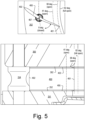
- Fig. 5 shows a plan view and a cut-away view of a portion of the cartridge 250 where various angles are indicated, including a 0 degree closed angle with a corresponding circle, a 41 degree open angle with a corresponding circle, a 68 degree angle with a corresponding circle and a 82 degree full open angle with a corresponding circle.
- the vane 400 includes a trailing edge 401 and a leading edge 402 with a pressure side airfoil and a suction side airfoil that meet at the trailing edge 401 and the leading edge 402.
- the vane 400 can have a planar upper surface 403 and a planar lower surface 405 where a clearance exists between the planar upper surface 403 and the upper nozzle surface 302 of the wall component 300 and/or where a clearance exists between the planar lower surface 405 and lower nozzle surface 252 of the plate component 251.
- the trailing edge 401 or the leading edge 402 may be disposed a distance from a pivot axis 407 of the vane 400 such that upon pivoting of the vane 400, the leading edge 402 and/or the trailing edge 401 sweeps a maximum arc of the vane 400 for a desired amount of pivoting.
- the vane 400 may bind (e.g., stick), where the risk may increase depending on arc length as interaction area can increase with respect to arc length.
- deformation to the nozzle wall component 300 may cause the vane 400 to bind upon pivoting or even in a static position. Binding (e.g., sticking) can result in loss of control, stress to a control mechanism, wear, etc.
- a turbine assembly can include a non-uniform or variable clearance between an upper surface of a vane and an upper nozzle surface.
- the clearance can increase with respect to decreasing radius of the upper nozzle surface.
- the clearance may be sufficiently small in a closed position of vanes for purposes of reduced exhaust leakage and be larger in an open position of the vanes for purposes of reduced binding and/or decreased resistance to exhaust flow.
- a clearance may increase for vane open positions that are greater than or equal to 50 percent of a fully open position.
- the vane open position where clearance increases may be defined using an angle, a diameter, etc., for example, as explained with respect to the example of Fig. 4 .
- Fig. 6 shows a perspective view of the vane 400 where a pressure side airflow surface 404 and a suction side airflow surface 408 are indicated with respective labels. Further, an outline of the upper nozzle surface 302 is shown as existing above the vane 400 as would be present in an assembled turbine assembly where the nozzle surface 302 can be a relatively constant region that meets a first transition point 304 that meets a variable region 306 that meets a second transition point 307 that meets an elevated region 308.
- a vane height z v various dimensions are illustrated, including a vane height z v , a nozzle height z n (e.g., between nozzle surfaces 302 and 252), a clearance z c (e.g., between surfaces 403 and 302), a variable clearance z c (r) and an enlarged clearance z c ⁇ .
- the first transition point 304 can correspond to a 50 percent open position of the trailing edge 401 of the vane 400.
- a vane may be defined in part via one or more airfoil terms (e.g., dimensions, etc.).
- the vane 400 can be defined in part by one or more of a camber line that can be a surface mid-way between the surfaces 404 and 408, a chord length, a thickness, an upper camber, a lower camber, a pivot axis, etc.
- the vane 400 is shown as being relatively slender with a thickness that is less than the chord length. As shown in Fig.
- the vane 400 can have its pivot axis 407 located approximately mid-way between the leading and trailing edges 402 and 401; noting that the vane 400 has a length from the pivot axis 407 to the trailing edge 401 that is greater than a length from the pivot axis 407 to the leading edge 402 such that, if the vane 400 was spun 360 degrees about its pivot axis 407 (e.g., as a single vane without interference from other vanes), the leading edge 402 would form a circle centered on the pivot axis 407 with a smaller radius than a circle centered on the pivot axis 407 for the trailing edge 401.
- Fig. 7 shows a plan view and a cut-away view of the example of Fig. 5 , however, with a different clearance profile between the vane 400 and the upper nozzle surface 302, as represented by at least the first transition point 304, the variable surface region 306 and the second transition point 307, which may transition to a shroud profile 308 that may transition to a relatively vertical surface 309.
- the vane 400 can have reduced risk of binding at open angles greater than approximately 41 degrees, which may be a half-open angle, compared to the 82 degree full open angle (e.g., fully open).
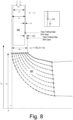
- Fig. 8 shows a schematic view of the vane 400 and a blade 600 of a turbine wheel.
- the increased clearance region can be defined using the vane height z v .
- a nozzle height z n that can increase to 1.05 to 1.5 times the nozzle height z n of vane open positions less than 50 percent open.
- the blade 600 can have a leading edge that can be disposed at a radius r w from a rotational axis z of a wheel having the blade 600 and the trailing edge of the vane 400 can be at a radius r te that depends on an angle of the vane 400. As the vane 400 becomes more open, the trailing edge of the vane 400 becomes closer to the leading edge of the blade 600.
- a blade may be a radial flow blade of a radial flow turbine wheel or a mixed flow blade of a mixed flow turbine wheel.
- the blade 600 may be a radial flow blade as the leading edge of the blade 600 is at a constant radius r w along the height of the leading edge of the blade 600.
- nozzle height z n is approximately 9.07 mm where the increased nozzle height z th (e.g., throat height) is approximately 11 mm.
- the radius of the 50 percent open position may be approximately 46.5 mm from a rotational axis of a turbine wheel and the 60 percent open position may be approximately 42.4 mm from the rotational axis of the turbine wheel.
- an increase may be approximately 0.5 mm to 2 mm or more.
- exhaust flow may exhibit improved development before experiencing leading edges of blades of a turbine wheel.
- a spacer can define a nozzle height.
- a spacer that defines a nozzle height of 9.07 mm where a clearance between a vane upper surface and a nozzle upper surface is approximately 0.15 mm.
- the clearance may increase to at least 0.5 mm.
- an increased clearance may provide for an increased flow bypass channel that is defined by a percentage of vane height (e.g., 5 percent to 30 percent or optionally more).
- the increase may be sloped, stepped, etc.
- a sloped region may be provided with one or more slopes and/or a stepped region may be provided with an approximately 90 degree step.
- one or more of a combination of shapes may be utilized to increase clearance.
- Fig. 9 shows a schematic view of the vane 400 and an example of the blade 600 of a turbine wheel.
- the blade 600 may be a mixed flow blade as the leading edge of the blade 600 is not at a constant radius such that the radius r w can vary along the height of the leading edge of the blade 600 (e.g., to define a cone angle).
- an approach as in Fig. 8 and/or an approach as in Fig. 9 may be utilized with a radial flow turbine wheel or a mixed flow turbine wheel.
- increased clearance regions can be defined using the vane height z v .
- a nozzle height z n that can increase to 1.05 to 1.5 times the nozzle height z n of vane open positions less than 50 percent open.
- the increase in clearance may be due to shape of a lower nozzle surface (e.g., the surface 252, etc.) and/or an upper nozzle surface (e.g., the surface 302, etc.).
- one or more of a combination of shapes may be utilized to increase clearance.
- Fig. 10 shows a cut-away view of a portion of an assembly 1000 that includes the vane 400, component 700 and 760, and a turbine housing 800.
- the component 700 and the turbine housing 800 can be assembled using one or more seal members 900 (e.g., piston rings, etc.).
- the component 700 may be floating and biased downwardly during operation by a pressure force or it may be biased by a spring force or it may be fit to one or more spacers.
- Fig. 10 also shows an inset view where the vane 400 is shown by dashed lines as its position depends on pivot angle.
- the vane can be in a fully open position (e.g., maximum open pivot angle).
- the turbine wheel 264 can be defined by a turbine wheel radius r w and the trailing edge of the vane 400 can be defined by a trailing edge radius r te as in the fully open position.
- the radius r te of the trailing edge of the vane 400 can be approximately 3 percent to approximately 10 percent more than the radius r w of the turbine wheel (e.g., maximum outer radius).
- the radius of the trailing edge r te will be greater than in the fully open position.
- a range of vane angles that is from closed to fully open can be defined via such radii where an open position, such as 50 percent, can be defined as being intermediate the closed position and the fully open position.
- the component 700 can be a substantially annular component that defines clearances with respect to the upper surface 403 of the vane 400.
- the second transition point 707 can be at an innermost end of the component 700 where the one or more seal members 900 can provide for sealing as to exhaust movement from a volute 866 to the nozzle or vice versa.
- the turbine housing 800 includes a lower surface 802 that transitions to a shroud surface 808.
- the turbine housing 800 can also include various annular notch features that can accommodate the component 700. For example, consider cylindrical surfaces 812 and 816, which may be separated by an annular recess 814 that can provide for positioning and stabilizing the one or more seal members 900. As shown, the cylindrical surface 816 can extend to an axial face 820, which may then transition to a surface 826 that defines in part the volute 866.
- a region of constant clearance of approximately 0.12 mm may be increased via a slope (e.g., a conical shape) to a region with a clearance that is at least approximately 0.175 mm.
- a clearance between the upper surface 403 of the vane 400 and the surface 802 of the turbine housing 800 may be approximately 0.8 mm.
- the increased clearance can span in part the component 700 and can span in part the turbine housing 800.
- exhaust flow may utilize the additional space (e.g., increased nozzle space, etc.) for some expansion and/or development prior to encountering a turbine wheel. In such an approach, some amount of efficiency may be gained by the increased space.
- the component 760 can include a lower nozzle surface 762 that meets a first transition point 764 that meets a variable surface region 766 that meets a second transition point 767. As shown, the second transition point 767 can be at an innermost end of the component 760. As shown, the components 700 and 760 may be shaped differently though providing for an increased clearance for a range of vane open positions. As an example, the assembly 1000 may include features as to an upper nozzle surface and/or features as to a lower nozzle surface to provide for increased clearance for a range or ranges of vane open positions.
- a cartridge and a turbine housing may be shaped such that upon installation of the cartridge in the turbine housing, contact does not occur between vanes and the turbine housing.
- rims may contact before contact between vanes and the turbine housing can occur.
- risk of the upper surface 403 of the vane 400 contacting the surface 802 of the turbine housing 800 can be reduced.
- the component 700 may be of an axial height such that the component 700 contacts the surface 820 before contact between the surface 802 and the upper surface 403 of the vane 400 can occur.
- a cartridge may be axially movable in a turbocharger via one or more spring-like mechanism.
- a shroud surface is positioned on a turbine housing rather than a component such as the component 700, clearance between a turbine wheel and the shroud surface may be more certain during operation.
- the component 700 may be smaller when compared, for example, to the component 300 of Fig. 2 , which may provide for lesser thermal effects, stresses, etc. Further, in the assembly 1000, the shroud contour for the turbine wheel is on the turbine housing and not the component 700. Also, by having the component 700 thinner at its inner end compared to its outer end, some thermal effects may be reduced (e.g., consider thermal expansion and contraction due to volume).
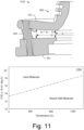
- Fig. 11 shows an approximate cutaway view of a portion of an assembly 1102 during a transient in temperature, where the assembly 1102 includes the plate component 251, the spacer 254 and the annular plate portion 310 of the nozzle wall component 300, along with a plot 1104 of coefficients of thermal expansion (CTE) with respect to temperature.
- CTE coefficients of thermal expansion
- a vane can be made of a material that has a higher CTE than a material of a nozzle wall (e.g., upper and/or lower).
- a vane is generally made from a higher CTE material and smaller (less volume) than a nozzle wall, the vane will react more rapidly to a change in temperature than a nozzle wall (e.g., the plate component 251, the annular plate portion 310, etc.).
- a vane has less mass, it has less thermal capacity so it will heat and cool faster than a nozzle wall(s) even if materials utilized have the same CTE. As such, clearance(s) can be altered, including being reduced.
- a cold clearance e.g., ambient temperature
- a hot clearance of approximately 0.06 mm.
- clearances can be as suitably designed as components can be at steady state temperature distribution.
- one or more increased clearances can be provided such that dynamic operation under dynamic thermal conditions does not lead to control issues (e.g., sticking, binding, etc.).
- a temperature transient can be non-uniform as defined about a rotational axis such that individual vanes in a set of vanes can be experiencing different temperatures.
- one or more of the individual vanes may be more likely to stick (e.g., bind) than one or more others, which may also cause uneven (e.g., non-uniform) wear in a turbine assembly.
- risk of one or more of the individual vanes sticking can be reduced; noting that control issues can arise from sticking (e.g., binding) of a single vane in a set of vanes.
- the nozzle space as defined by the components 251 and 300, can become V-shaped due to the thermal gradient between the outer and the inner radius of the components 251 and 300 along with the spacer 254 causing some limitations and due to spring-like support from the heat shield 290 pressing at and/or near an inner radius of the component 251.
- axial heights z rb at a radius "b" and z ra at a radius "a" are shown where, during a temperature transient, z rb is greater than z ra hence forming a V-shape in cross-section.
- utilization of one or more components that can increase clearance between a nozzle wall and a vane can reduce risk of vane sticking (e.g., binding, etc.).
- by increasing clearance(s) between a vane and one or more nozzle surfaces near and/or at an inner perimeter of a component or components e.g., to be more than at or near an outer perimeter
- performance may be improved (e.g., controllability, lifespan, etc.).
- NI-RESIST high nickel alloy cast irons
- NITRONIC 60 alloy 218, e.g., Cr 17, Mn 8, Ni 8.5, Si 4, N 0.13, C 0.10, Fe balance
- SS stainless steel
- a component that defines a nozzle space e.g., a component that forms a nozzle wall
- Fig. 12 shows another cut-away view of the example assembly 1000 of Fig. 10 , without the vane 400 and without the one or more seal members 900.
- the component 700 can include the upper nozzle surface 702 as a substantially level portion that defines a constant nozzle height where the surface 702 meets a first transition point 704 that meets a variable surface region 706 that increases nozzle height with respect to decreasing radius that meets a second transition point 707 that meets a cylindrical surface 708 that can define an inner perimeter of the component 700.
- the turbine housing 800 can include the surface 802 as being positioned at a greater axial height than the second transition point 707.
- the turbine housing 800 can also include a surface 809 that meets the shroud surface 808 where the surface may define a minimum diameter of the turbine housing 800.
- the component 700 may be formed via one or more processes to provide for a change in nozzle height. For example, consider machining where such machining can grind a beveled region into a stock non-beveled surface (see, e.g., the surface 702). As an example, one or more bevels may be imparted such that one or more angles, transitions, etc., are formed.
- Fig. 13 shows another cut-away view of the example assembly 1000 of Fig. 10 .
- the vane 400 can be seen, particularly in relationship to the components 700 and 760 and the housing 800 where a substantial portion of the vane 400 has an increased clearance in the open position of the vane 400 as shown.
- such an approach can reduce risk of binding and/or reduce resistance to exhaust flow when a vane is in an open position that is at or beyond 50 percent open.
- Fig. 14 shows a cut-away view of the example assembly 1000 with the turbine housing 800 and the component 700.
- one or more features of the cartridge 250 of Figs. 2 , 3A and 3B may be included in such an assembly.
- a turbine assembly with an increased vane to nozzle clearance for vane open positions greater than or equal to 50 percent can provide for an expansion flow pass to reduce shock strength at high pressure ratio (PR), can provide for performance map width extension to increase flow capacity without a change to vane height, can maintain the same performance at a vanes position less than 50 percent closed, can lower vane aerodynamic torque (e.g., provide for smaller vane height than end wall height), can reduce risk of vane/nozzle wall friction due to thermal expansion, thermal distortion or combustion residual deposits.
- PR shock strength at high pressure ratio
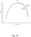
- Fig. 15 shows an example plot 1500 of trial results for two different assemblies for a given pressure ratio (PR) where one of the assemblies includes an increased clearance for vane open positions of at least 50 percent (e.g., increased clearance) and where the other one of the assemblies includes a constant clearance.
- PR pressure ratio
- the assembly with increased clearance can provide for increased efficiency at higher corrected mass flow (kg/s) compared to the constant clearance assembly.
- the two assemblies exhibit the same or similar performance.
- the difference may be defined with respect to a maximum efficiency (e.g., a corrected mass flow that corresponds to a peak efficiency for a particular vanes position).
- Fig. 16 shows an example plot 1600 of trial results for two different assemblies for a given pressure ratio (PR) where one of the assemblies includes an increased clearance for vane open positions of at least 50 percent (e.g., increased clearance) and where the other one of the assemblies includes a constant clearance.
- PR pressure ratio
- the assembly with increased clearance can provide for increased efficiency at higher corrected mass flow (kg/s) compared to the constant clearance assembly.
- the two assemblies exhibit the same or similar performance.
- the difference may be defined with respect to a maximum efficiency (e.g., a corrected mass flow that corresponds to a peak efficiency for a particular vanes position).
- the increased clearance example exhibits improved efficiency after a vanes open position of 50 percent.
- high end performance is improved without performance difference at the low end.
- high cycle fatigue (HCF) loading can be reduced (e.g., early expansion of flow before the wheel leading edge).
- HCF high cycle fatigue
- an annular clearance can exist between vane trailing edges and a turbine wheel where such an annular clearance may be defined by a radius of the turbine wheel.
- such a clearance can be between approximately 3 percent and 10 percent of the radius of a turbine wheel.
- a turbocharger turbine assembly may be made with vanes of a lesser vane height while being able to achieve suitable performance at high mass flow rates.
- vane loading may be reduced, which can provide for a reduction in actuation force and hence allow for a smaller actuator (e.g., an actuator with lesser maximum force).
- a reduced risk of sticking e.g., binding
- a smaller actuator e.g., an actuator with lesser maximum force
- a method can include determining a vanes position for a maximum efficiency with respect to corrected mass flow.
- the vanes position can be translated into a radius or diameter as to trailing edges of the vanes.
- a component or components of a cartridge may be machined to provide for increased clearance (e.g., exhaust passage) for vanes position equal to or greater than the vanes position that corresponds to the maximum efficiency.
- vane top and/or bottom clearance in a nozzle can have a detrimental impact on VNT stage performance.
- such clearances are maintained as small as possible along an entire vane opening range which increases the risk of vane binding (e.g., sticking) and/or vane to nozzle/pipe friction.
- a larger vane height is needed, which, in turn, increases vane loading.
- a larger actuator is needed to pivot the vanes.
- an assembly can include an increased clearance region for passage of exhaust above and/or below each vane in a nozzle, which can improve high end performance, lower HCF excitation and reduce risk of vane to nozzle wall(s) friction or sticking.
- an increased clearance as a bypass passage at/near the inner perimeter of a nozzle ring, the performance flow range can be increased while using a smaller vane height for a lower actuation force.
- a method can include machining a stock annular component (e.g., as a hat or flat component) and/or selecting vanes with a smaller height.
- a turbine housing assembly can include a turbine housing that defines a rotational axis for a turbine wheel; and a cartridge receivable by the turbine housing, where the cartridge includes a nozzle wall component with an upper nozzle surface and a plate component with a lower nozzle surface, where the upper nozzle surface and the lower nozzle surface define a nozzle space, and vanes positioned in the nozzle space, where the vanes are pivotable between a closed vanes position of 0 percent open and a fully open vanes position of 100 percent open, and where, for a vanes position of at least 50 percent open and less than 75 percent open, an axial dimension of the nozzle space increases with respect to decreasing radius as measured from the rotational axis.
- the axial dimension of the nozzle space can be constant.
- an axial dimension of a nozzle space can increase with respect to decreasing radius at a transition radius, where the transition radius is defined by trailing edges of the vanes for a vanes position of at least 50 percent open and less than 75 percent open.
- the vanes position can correspond to a maximum efficiency with respect to corrected mass flow.
- annular clearance can exist with respect to a turbine wheel and trailing edges of vanes, where the annular clearance can be at least 3 percent of a radius of the turbine wheel and less than 10 percent of the radius of the turbine wheel.
- a closed vanes position contact can exist between adjacent vanes.
- the contact can act to limit rotation (e.g., pivoting) of the vanes.
- a cartridge, a control linkage, etc. may include one or more features that act as a physical stop that may define a closed vanes position.
- the vanes may be nearly in contact where throats defined between adjacent vanes are small such that the vanes act as barriers to exhaust flow from a volute to a turbine wheel space.
- nearly in contact may be defined via a vane-to-vane clearance (e.g., throat width) of less than approximately 3 mm.
- a closed vanes position can define a minimum exhaust flow condition for a turbine housing assembly while a fully open position may define a maximum exhaust flow condition for a turbine housing assembly.
- an axial dimension of a nozzle space can increase to a constant axial dimension.
- an axial dimension of a nozzle space can increase according to a slope and/or a step.
- each of a plurality of vanes can have a constant axial vane height between a respective trailing edge and a respective leading edge. For example, consider a slight chamfer at a leading edge and a slight chamfer at a trailing edge where the axial vane height is constant over approximately 90 percent or more of a length of the vane.
- a turbine housing assembly can include a component that defines a nozzle space where a surface of the component provides an upper nozzle surface that is sloped and/or can include a component that defines a nozzle space where a surface of the component provides a lower nozzle surface that is sloped.
- a turbine housing assembly can include a component that defines a nozzle space where a surface of the component provides an upper nozzle surface that is stepped and/or can include a component that defines a nozzle space where a surface of the component provides a lower nozzle surface that is stepped.
- a turbine housing assembly can include a component that defines a nozzle space where a surface of the component provides an upper nozzle surface that is sloped and/or stepped and/or can include a component that defines a nozzle space where a surface of the component provides a lower nozzle surface that is sloped and/or stepped.
- a turbine housing assembly can include a turbine housing that includes a shroud surface.
- the shroud surface can define in part a turbine wheel space for a turbine wheel.
- a turbine housing assembly can include a nozzle wall component that includes a shroud surface.
- the shroud surface can define in part a turbine wheel space for a turbine wheel.
- a method can include operating a turbine housing assembly that includes a turbine housing that defines a rotational axis for a turbine wheel; and a cartridge receivable by the turbine housing, where the cartridge includes a nozzle wall component with an upper nozzle surface and a plate component with a lower nozzle surface, where the upper nozzle surface and the lower nozzle surface define a nozzle space, and vanes positioned in the nozzle space, where the vanes are pivotable between a closed vanes position of 0 percent open and a fully open vanes position of 100 percent open, and where, for a vanes position of at least 50 percent open and less than 75 percent open, an axial dimension of the nozzle space increases with respect to decreasing radius as measured from the rotational axis; flowing exhaust in clearances between the vanes and the upper nozzle surface; and, responsive to pivoting the vanes from a vanes position less than 50 percent open to a vanes position greater than 75 percent open, flowing exhaust in increased clearances between the vanes and the upper nozzle surface.
- the increased clearances can reduce risk of binding of the vanes in the nozzle space and/or the increased clearances can promote development of exhaust flow prior to a turbine wheel space (e.g., in a region adjacent to a turbine wheel space where the region includes the increased clearances).
Landscapes
- Engineering & Computer Science (AREA)
- Mechanical Engineering (AREA)
- General Engineering & Computer Science (AREA)
- Chemical & Material Sciences (AREA)
- Combustion & Propulsion (AREA)
- Supercharger (AREA)
Abstract
Description
- Subject matter disclosed herein relates generally to turbochargers for internal combustion engines.
- Exhaust driven turbochargers include a rotating group that includes a turbine wheel and a compressor wheel that are connected to one another by a shaft. The shaft is typically rotatably supported within a center housing by one or more bearings. During operation, exhaust from an internal combustion engine drives a turbocharger's turbine wheel, which, in turn, drives the compressor wheel to boost charge air to the internal combustion engine.
- A more complete understanding of the various methods, devices, assemblies, systems, arrangements, etc., described herein, and equivalents thereof, may be had by reference to the following detailed description when taken in conjunction with examples shown in the accompanying drawings where:
-
Fig. 1 is a diagram of a turbocharger and an internal combustion engine along with a controller; -
Fig. 2 is a cutaway view of an example of a turbocharger; -
Figs. 3A and 3B are perspective views of an example of a cartridge of a turbocharger; -
Fig. 4 is a cutaway plan view of the cartridge ofFigs. 3A and 3B ; -
Fig. 5 is series of views of a portion of the cartridge ofFigs. 3A and 3B ; -
Fig. 6 is a perspective view of an example of a vane and an example of a nozzle surface; -
Fig. 7 is a series of views of a portion of the cartridge ofFigs. 3A and 3B where an increased clearance exists between a vane and a nozzle surface; -
Fig. 8 is a schematic view of an example of a vane with respect to a nozzle and a turbine wheel blade; -
Fig. 9 is a schematic view of an example of a vane with respect to a nozzle and a turbine wheel blade; -
Fig. 10 is a cutaway view of a portion of an example of an assembly; -
Fig. 11 is a cutaway view of a portion of an example of an assembly and a plot of coefficients of thermal expansion versus temperature for materials; -
Fig. 12 is a cutaway view of a portion of an example of the assembly ofFig. 10 ; -
Fig. 13 is a cutaway view of a portion of an example of the assembly ofFig. 10 ; -
Fig. 14 is a cutaway view of an example of the assembly ofFig. 10 ; -
Fig. 15 is an example plot of trial data; and -
Fig. 16 is an example plot of trial data. - Below, an example of a turbocharged engine system is described followed by various examples of components, assemblies, methods, etc.
- Turbochargers are frequently utilized to increase output of an internal combustion engine. Referring to
Fig. 1 , as an example, asystem 100 can include aninternal combustion engine 110 and aturbocharger 120. As shown inFig. 1 , thesystem 100 may be part of avehicle 101 where thesystem 100 is disposed in an engine compartment and connected to anexhaust conduit 103 that directs exhaust to anexhaust outlet 109, for example, located behind apassenger compartment 105. In the example ofFig. 1 , atreatment unit 107 may be provided to treat exhaust (e.g., to reduce emissions via catalytic conversion of molecules, etc.). - As shown in
Fig. 1 , theinternal combustion engine 110 includes anengine block 118 housing one or more combustion chambers that operatively drive a shaft 112 (e.g., via pistons) as well as anintake port 114 that provides a flow path for air to theengine block 118 and anexhaust port 116 that provides a flow path for exhaust from theengine block 118. - The
turbocharger 120 can act to extract energy from the exhaust and to provide energy to intake air, which may be combined with fuel to form combustion gas. As shown inFig. 1 , theturbocharger 120 includes anair inlet 134, ashaft 122, acompressor housing assembly 124 for acompressor wheel 125, aturbine housing assembly 126 for aturbine wheel 127, anotherhousing assembly 128 and anexhaust outlet 136. Thehousing assembly 128 may be referred to as a center housing assembly as it is disposed between thecompressor housing assembly 124 and theturbine housing assembly 126. - In
Fig. 1 , theshaft 122 may be a shaft assembly that includes a variety of components (e.g., consider a shaft and wheel assembly (SWA) where theturbine wheel 127 is welded to theshaft 122, etc.). As an example, theshaft 122 may be rotatably supported by a bearing system (e.g., journal bearing(s), rolling element bearing(s), etc.) disposed in the housing assembly 128 (e.g., in a bore defined by one or more bore walls) such that rotation of theturbine wheel 127 causes rotation of the compressor wheel 125 (e.g., as rotatably coupled by the shaft 122). As an example a center housing rotating assembly (CHRA) can include thecompressor wheel 125, theturbine wheel 127, theshaft 122, thehousing assembly 128 and various other components (e.g., a compressor side plate disposed at an axial location between thecompressor wheel 125 and the housing assembly 128). - In the example of
Fig. 1 , avariable geometry assembly 129 is shown as being, in part, disposed between thehousing assembly 128 and thehousing assembly 126. Such a variable geometry assembly may include vanes or other components to vary geometry of passages that lead to a turbine wheel space in theturbine housing assembly 126. As an example, a variable geometry compressor assembly may be provided. - In the example of
Fig. 1 , a wastegate valve (or simply wastegate) 135 is positioned proximate to an exhaust inlet of theturbine housing assembly 126. Thewastegate valve 135 can be controlled to allow at least some exhaust from theexhaust port 116 to bypass theturbine wheel 127. Various wastegates, wastegate components, etc., may be applied to a conventional fixed nozzle turbine, a fixed-vaned nozzle turbine, a variable nozzle turbine, a twin scroll turbocharger, etc. As an example, a wastegate may be an internal wastegate (e.g., at least partially internal to a turbine housing). As an example, a wastegate may be an external wastegate (e.g., operatively coupled to a conduit in fluid communication with a turbine housing). - In the example of
Fig. 1 , an exhaust gas recirculation (EGR)conduit 115 is also shown, which may be provided, optionally with one ormore valves 117, for example, to allow exhaust to flow to a position upstream thecompressor wheel 125. -
Fig. 1 also shows anexample arrangement 150 for flow of exhaust to an exhaustturbine housing assembly 152 andanother example arrangement 170 for flow of exhaust to an exhaustturbine housing assembly 172. In thearrangement 150, acylinder head 154 includespassages 156 within to direct exhaust from cylinders to theturbine housing assembly 152 while in thearrangement 170, amanifold 176 provides for mounting of theturbine housing assembly 172, for example, without any separate, intermediate length of exhaust piping. In theexample arrangements turbine housing assemblies - In
Fig. 1 , an example of acontroller 190 is shown as including one ormore processors 192,memory 194 and one ormore interfaces 196. Such a controller may include circuitry such as circuitry of an engine control unit (ECU). As described herein, various methods or techniques may optionally be implemented in conjunction with a controller, for example, through control logic. Control logic may depend on one or more engine operating conditions (e.g., turbo rpm, engine rpm, temperature, load, lubricant, cooling, etc.). For example, sensors may transmit information to thecontroller 190 via the one ormore interfaces 196. Control logic may rely on such information and, in turn, thecontroller 190 may output control signals to control engine operation. Thecontroller 190 may be configured to control lubricant flow, temperature, a variable geometry assembly (e.g., variable geometry compressor or turbine), a wastegate (e.g., via an actuator), an electric motor, or one or more other components associated with an engine, a turbocharger (or turbochargers), etc. As an example, theturbocharger 120 may include one or more actuators and/or one ormore sensors 198 that may be, for example, coupled to an interface orinterfaces 196 of thecontroller 190. As an example, thewastegate 135 may be controlled by a controller that includes an actuator responsive to an electrical signal, a pressure signal, etc. As an example, an actuator for a wastegate may be a mechanical actuator, for example, that may operate without a need for electrical power (e.g., consider a mechanical actuator configured to respond to a pressure signal supplied via a conduit). -
Fig. 2 shows an example of aturbocharger assembly 200 that includes ashaft 220 supported by a bearing 230 (e.g., a journal bearing, a bearing assembly such as a rolling element bearing with an outer race, etc.) disposed in a bore (e.g., a through bore defined by one or more bore walls) of ahousing 280 between acompressor assembly 240 that defines a compressor side (left) and aturbine assembly 260 that defines a turbine side (right). Thecompressor assembly 240 includes acompressor housing 242 that defines avolute 246 and that houses acompressor wheel 244. As shown inFig. 2 , theturbine assembly 260 includes aturbine housing 262 that defines avolute 266 and that houses aturbine wheel 264. Theturbine wheel 264 may be, for example, welded or otherwise attached to theshaft 220 to form a shaft and wheel assembly (SWA) where a free end of theshaft 220 allows for attachment of thecompressor wheel 244. - As an example, a wheel, whether a turbine wheel or a compressor wheel, can include an inducer portion and an exducer portion, for example, characterized in part by an inducer radius (n) and an exducer radius (re). As an example, an individual blade can include an inducer edge (e.g., a leading edge) and an exducer edge (e.g., a trailing edge). A wheel may be defined in part by a trim value that characterizes a relationship between inducer and exducer portions.
- For a compressor wheel, the inducer portion can be characterized by a "minor" diameter; whereas, for a turbine wheel, the inducer portion can be characterized by a "major" diameter. During operation, inlet flow to a compressor wheel or a turbine wheel occurs with respect to its inducer portion and outlet flow from a compressor wheel or a turbine wheel occurs with respect to its exducer portion.
- As to air flow, during operation of the
turbocharger 200, air can be directed from thecompressor wheel 244 to thevolute 246 via a diffuser section defined in part by thecompressor housing 242 and acompressor side plate 270 as thecompressor wheel 244 rotates, drawing air into apassage 248 via aninlet 249, both of which may be defined by thecompressor housing 242. As indicated inFig. 2 , during operation of theturbocharger 200, thecompressor wheel 244 acts to boost air pressure such that air pressure in the volute 246 (Pcv) is greater than air pressure in the passage 248 (Pco). Rotation of thecompressor wheel 244 can generate a negative pressure that acts to "suck" air into thecompressor assembly 240 and to direct such air to thevolute 246 via the diffuser section. As an example, where exhaust gas recirculation (EGR) is implemented, environmental air may be mixed with exhaust (e.g., upstream and/or downstream of the compressor wheel 244). - In the example of
Fig. 2 , anaxial locating pin 285 is received in an opening of thebearing 230, which may be a cross-bore of thebearing 230. As an example, one or more other types of axial locating mechanisms may be included in a turbocharger that act to limit axial movement of a bearing (e.g., and/or movement in one or more other directions). As an example, a locating pin may allow for radial movement of a bearing, which may allow for effective operation of one or more lubricant films disposed about a surface of the bearing. - In the example of
Fig. 2 , theshaft 220 includes a step (e.g., a shoulder) that forms an axial annular face. In the example ofFig. 2 , a thrust collar 275 (e.g., a type of collar) includes a surface that is seated against the axial annular face of theshaft 220. In such an example, alock nut 221 can include threads that match threads of an end portion of theshaft 220 such that tightening of thelock nut 221 with respect to theshaft 220 loads thecompressor wheel 244 and thethrust collar 275 against the axial annular face of theshaft 220, which can place the shaft 220 (e.g., from the step to its end portion) in tension. In such an example, theshaft 220, thecompressor wheel 244 and thelock nut 221 can rotate as a unit (e.g., responsive to exhaust driving the turbine wheel 264). As shown in the example ofFig. 2 , thecompressor side plate 270 can include a bore (e.g., an opening) in which at least a portion of thethrust collar 275 is positioned where the thrust collar 275 (and/or the compressor side plate 270) can include a groove or grooves that may seat a seal element or seal elements (e.g., O-rings, piston rings, etc.). - In the example of
Fig. 2 , theturbine assembly 260 includes avariable geometry assembly 250, which may be referred to as a "cartridge" (e.g., the cartridge 250), that may be positioned using anplate component 251, which may be referred to as a flange (e.g., optionally shaped as a stepped annular disc or annular plate), of thecartridge 250 that clamps between thehousing 280 and theturbine housing 262, for example, using bolts 293-1 to 293-N and a heat shield 290 (e.g., optionally shaped as a stepped annular disc), the latter of which is disposed between thecartridge 250 and thehousing 280 and may be resilient in that it can apply a biasing force. As shown in the example ofFig. 2 , thecartridge 250 includes anozzle wall component 300 and theplate component 251. As an example, one or more mounts orspacers 254 may be disposed between thenozzle wall component 300 and the plate component 251 (e.g., or annular plate component), for example, to axially space thenozzle wall component 300 and the plate component 251 (e.g., forming a nozzle space). - As an example,
vanes 400 may be positioned between thenozzle wall component 300 and theplate component 251, for example, where a control mechanism may cause pivoting of thevanes 400. As an example, thevane 400 may include avane post 420 that extends axially to operatively couple to a control mechanism, for example, for pivoting of thevane 400 about a pivot axis defined by thevane post 420. - As to exhaust flow, during operation of the
turbocharger 200, higher pressure exhaust in the volute 266 passes through passages (e.g., a nozzle or nozzles, a throat or throats, etc.) of thecartridge 250 to reach theturbine wheel 264 as disposed in a turbine wheel space defined at least in part by thecartridge 250 and at least in part by theturbine housing 262. After passing through the turbine wheel space, exhaust travels axially outwardly along apassage 268 defined by a wall of theturbine housing 262 that also defines an opening 269 (e.g., an exhaust outlet). As indicated, during operation of theturbocharger 200, exhaust pressure in the volute 266 (Ptv) is greater than exhaust pressure in the passage 268 (Pto). - As an example, exhaust pressure in the
turbine assembly 260 can depend on position or positioning of thevanes 400. For example, closing and/or opening of the vanes 400 (e.g., narrowing or widening throats) can effect exhaust gas pressure at one or more locations. - While
Fig. 2 shows a general direction of gravity (G, Earth's gravity), the orientation of theturbocharger 200 may be in an orientation in an engine compartment that is suitable for operation given particulars of lubricant feed, flow and drainage. - As an example, a turbine assembly of an exhaust gas turbocharger can include vanes as part of a variable geometry turbine (VGT) or variable nozzle turbine (VNT). Vanes may be disposed at least in part in a cartridge where the cartridge is disposed between a turbine housing and a center housing of a turbocharger.
- As an example, a cartridge may include a nozzle wall component and a plate component spaced axially by mounts (e.g., spacers) where vanes are accommodated to control exhaust flow from a volute to a turbine wheel space. As an example, a vane may include a trailing edge and a leading edge with a pressure side airfoil and a suction side airfoil that meet at the trailing edge and the leading edge. Such a vane may have a planar upper surface and a planar lower surface where a clearance exists between the planar upper surface and the nozzle wall component (e.g., between a lower planar surface of an annular portion of the nozzle wall component) and/or where a clearance exists between the planar lower surface and the plate component (e.g., between an upper planar surface of an annular portion of the plate component).
- As an example, each vane may include an axis about which the vane may pivot (e.g., a pivot axis). As an example, each vane may include a post (e.g., or axle) that defines a pivot axis. As an example, a post may be integral with a vane (e.g., cast as a single piece of metal, alloy, etc.) or a post may be a separate component that can be operatively coupled to a vane.
- As an example, movement of a vane (e.g., arcwise) may be less closer to the pivot axis and greater further away from the pivot axis. For example, a trailing edge or a leading edge may be disposed a distance from the pivot axis such that upon pivoting of a vane, the leading edge and/or the trailing edge sweeps a maximum arc of the vane for a desired amount of pivoting. If clearance between an upper surface of a vane and a lower surface of a nozzle wall component is diminished, the vane may bind (e.g., stick), where the risk may increase depending on arc length as interaction area can increase with respect to arc length. In such an example, deformation to a nozzle wall component may cause a vane or vanes to bind upon pivoting or even in a static position. Binding (e.g., sticking) can result in loss of control, stress to a control mechanism, wear, etc.
- As an example, forces acting on a vane and/or a post of a vane may cause a vane or vanes to bind upon pivoting or even in a static position. Binding can result in loss of control, stress to a control mechanism, wear, etc.
- As to pressure differentials and temperatures in a variable geometry turbine assembly, as an example, exhaust in a volute may have pressure in a range of approximately 120 kPa to approximately 400 kPa and possible peak pressure of up to approximately 650 kPa (absolute) and, for example, temperature in a range of approximately 150 degrees C to approximately 980 degrees C; whereas, at a location axially downstream of a turbine wheel, exhaust may have pressure in a lower range and temperature in a lower range. Exhaust gas temperatures in a gasoline fuel internal combustion engine may exceed those of a diesel fuel internal combustion engine. Where a variable geometry turbine assembly is utilized with a gasoline fuel internal combustion engine, the environment may be harsher in terms of temperature when compared to a diesel fuel internal combustion engine.
- As an example, one or more components of a variable geometry turbine assembly (e.g., VGT assembly or variable nozzle turbine (VNT) assembly) can include at least a portion made of a material that can withstand pressures and temperatures in the aforementioned ranges. For example, a material can be the INCONEL 718 alloy (Specialty Materials Corporation, New Hartford, NY). Some other examples of materials include INCONEL 625, C263 (aluminum-titanium age hardening nickel), Rene 41 (nickel-based alloy), WASPALOY alloy (age hardened austenitic nickel-based alloy, United Technologies Corporation, Hartford, CT), etc.
- As an example, a cartridge can include vanes that are disposed at least in part between two components. As an example, at least a portion of a vane may be made of a material such as HK30, which is a chromium-nickel-iron stainless steel alloy including approximately 30% chromium and 20% nickel, with the balance being predominantly iron (percentages by mass). As an example, at least a portion of a vane may be made of a HK series stainless steel alloy that includes about 18-22% nickel by mass. Such an alloy can be fully austenitic. As an example, one or more components of a cartridge may be made of a material such as, for example, PL23 alloy or 310 SS alloy.
- As an example, an exhaust gas variable geometry turbine assembly can include a number of pivotable vanes that define, at least in part, throats within an exhaust gas nozzle where each of the pivotable vanes includes a corresponding post.
-
Figs. 3A and 3B show perspective views of theexample cartridge 250 ofFig. 2 . InFigs. 3A and 3B , thenozzle wall component 300 includes a lower surface that can be a nozzleupper surface 302 of anannular plate portion 310. As an example, thenozzle wall component 300 can include acylindrical pipe portion 350. Where thenozzle wall component 300 includes thecylindrical pipe portion 350, the overall shape of thenozzle wall component 300 can be referred to as a hat shape. As shown, theannular plate portion 310 includes an outer perimeter defined by anouter surface 312. Theouter surface 312 meets opposingannular surfaces annular surface 316 includes ashroud portion 318 as a shroud of a turbine wheel space for a turbine wheel where a clearance exists between theshroud portion 318 and a suitable turbine wheel disposed in the turbine wheel space. - As shown, the
nozzle wall component 300 includes a plurality of bores 320-1, 320-2 and 320-3 (e.g., spacer bores), which receive a plurality of spacers 254-1, 254-2 and 254-3, which space thenozzle wall component 300 axially with respect to theplate component 251. As shown, theplate component 251 includes an upper surface that can be a nozzlelower surface 252 where a nozzle is defined by the nozzleupper surface 302 and the nozzlelower surface 252. The bores 320-1, 320-2 and 320-3 are shown as being cylindrical and extending between the opposingsurfaces nozzle wall component 300 where the bores 320-1, 320-2 and 320-3 each has a diameter and an axial length along a bore axis where the bore axes are at a radius of an axis defined by the turbine wheel space, for example, as defined by theshroud portion 318, which may be referred to as a rotational axis (e.g., an intended rotational axis of a turbine wheel disposed in the turbine wheel space). In the example ofFigs. 3A and 3B , thecartridge 250 can be installed in a turbocharger, which may then be installed in an engine compartment of an internal combustion engine. Thenozzle wall component 300 can be subjected to various conditions (e.g., forces, temperatures, pressures, etc.), which can impact the nozzle wall component 300 (e.g., as to integrity, shape, etc.). - As to the
cylindrical pipe portion 350, it includes aninner surface 352 and anouter surface 354, as well as anend surface 356. Thecylindrical pipe portion 350 can be defined at least in part by an inner diameter, an outer diameter and an axial length, for example, as measured along the rotational axis. In the example shown, theouter surface 354 includes one ormore grooves 355 that can receive one or more seal elements (e.g., seal components such as or akin to piston rings). In the example shown, thesurface 314 and thesurface 354 meet and form a shoulder that has an angle of approximately 90 degrees. As to thesurface 316 and thesurface 352, they meet at respective ends of theshroud portion 318. For example, thesurface 316 can be substantially flat, meet theshroud portion 318, which is contoured, which then meets thesurface 352, which extend axially to theend surface 356. As shown, theend surface 356 is an annular surface the meets theinner surface 352 and theouter surface 354. - The perspective views show one or more seal rings 261 seated in the one or
more grooves 355 of thenozzle wall component 300, the plurality of spacers 254-1, 254-2 and 254-3, a plurality of vanes 400 (e.g., 400-1 to 400-N) and corresponding vane posts 420-1 to 420-N, a plurality ofvane control arms 256, aunison ring 257, a plurality of pins 258-1, 258-2 and 258-3, and a plurality of guides 259-1, 259-2 and 259-3. - In the example of
Figs. 3A and 3B , theunison ring 257 may be rotated about a central axis (e.g., substantially aligned with the axis of rotation of a turbine wheel) to cause the plurality ofvane control arms 256 to rotate about respective post axes of individual vane posts 420 of the plurality ofvanes 400. The plurality of pins 258-1, 258-2 and 258-3 and the plurality of guides 259-1, 259-2 and 259-3 may help to align theunison ring 257 with respect to other components of thecartridge 250. - In the example of
Figs. 3A and 3B , one or more ends of the spacers 254-1, 254-2 and 254-3 may be fixed (e.g., riveted, capped, etc.). For example, an end of a spacer may be flattened to a radius that is greater than an opening of a bore through which the spacer extends such that the spacer cannot be moved axially into the bore. As shown, each of the spacers 254-1, 254-2 and 254-3 includes a nozzle portion with a radius and/or a diameter that is greater than a corresponding end portion of opposing end portions that are received by respective spacer bores of thenozzle wall component 300 and theplate component 251. For example, a spacer can be defined by one or more radii and/or one or more diameters as well as one or more axial dimensions such as an axial dimension of a nozzle portion. - The nozzle portion of each of the spacers 254-1, 254-2 and 254-3 can include opposing shoulders where one shoulder abuts the
nozzle wall component 300 and the other shoulder abuts theplate component 251 to define a nozzle axial dimension, which can be slightly larger than a vane axial dimension to allow vanes to pivot in the nozzle where a clearance may be defined based at least in part on one or more thermal considerations (e.g., thermal expansion, contraction, etc.). - In the example of
Figs. 3A and 3B , thecartridge 250 may be secured as a cartridge unit via riveting ends of the spacers 254-1, 254-2 and 254-3, which fixes an axial distance between thenozzle wall component 300 and theplate component 251 at a given temperature (e.g., an ambient temperature during assembly). Such a riveting process may introduce some amount of stress at the passages (e.g., bores) of thenozzle wall component 300 and/or theplate component 251 through which the spacers 254-1, 254-2 and 254-3 pass. -
Fig. 4 shows a plan view of a portion of acartridge 250 that includes a plurality ofvanes 400. Thevanes 400 are represented inFig. 4 via solid lines and dashed lines where the solid lines indicate an open position of thevanes 400 and where the dashed lines indicate a closed position of thevanes 400. Open headed arrows are shown to approximately illustrate the direction of exhaust flow between adjacent pairs of thevanes 400 when in the open position. In the closed position, thevanes 400 act as obstacles to exhaust flow such that pressure can be higher in a region radially outward from thevanes 400 in comparison to a region radially inwardly from thevanes 400. In such an example, clearances between thevanes 400 and the upper and lower nozzle surfaces 302 and 252 are minimal such that bypass of exhaust in such clearances is minimized. Exhaust flow that does occur may be referred to as exhaust leakage. As explained, however, the clearances are to be sufficient to reduce risk of binding where vane binding against the nozzle surfaces 302 and 252 can confound controllability. Where risk of binding exists, an actuator may demand more power, which may mean larger size, more cost, more energy consumption, etc. Hence, design of thecartridge 250 generally involves balancing risk of binding (e.g., sticking) and exhaust leakage in the closed position. - In the example of
Fig. 4 , in the open position, the trailing edges of thevanes 400 can define a circle as indicated by a thick dashed line and, in the closed position, the trailing edges of thevanes 400 can define another circle, which may be approximately the same as a circle that circumscribes the pivot axis (e.g., vanes posts 420) of thevanes 400. Hence, as thevanes 400 move from a closed position to an open position, a circle of decreasing radius (e.g., diameter) can be defined by the trailing edges of thevanes 400. Further, as shown, the leading edges of thevanes 400 may define a circle of increasing radius (e.g., diameter). - As an example, a range of angles for a set of vanes can be defined using a closed position and a fully open position. In such an example, the closed position may be defined where pivoting is limited for one or more reasons. For example, one reason for limitation of pivoting is vane contact where neighboring vanes contact each other (e.g., vane-to-vane contact). Another reason may be due to one or more stops that are built into an actuator or other control linkage. As to a fully open position, it can be defined utilizing one or more references. For example, an outer radius of a turbine wheel can be utilized where, in a fully open position, trailing edges of a set of vanes are within a range of approximately 3 percent to approximately 10 percent of the outer radius of the turbine wheel. In such a range, the trailing edges can be spaced a distance sufficiently away from blades of a turbine wheel such that leading edges of the blades do not contact trailing edges of the vanes when the set of vanes is in the fully open position. Such a distance can be tailored to be not too large for purposes of appropriate performance and not too small for purposes of avoiding turbine wheel-to-vane contact (e.g., given vibration, thrust forces on a turbine wheel, thermal effects, etc.). A range of angles can have a minimum angle and a maximum angle where an intermediate angle can be defined as being a 50 percent open angle. As explained, one or more features of a set of vanes (e.g., leading edges and/or trailing edges) may be utilized to define one or more radii (e.g., one or more diameters) that can be utilized to define one or more features of an assembly.
-
Fig. 5 shows a plan view and a cut-away view of a portion of thecartridge 250 where various angles are indicated, including a 0 degree closed angle with a corresponding circle, a 41 degree open angle with a corresponding circle, a 68 degree angle with a corresponding circle and a 82 degree full open angle with a corresponding circle. - As shown in the example of
Fig. 5 , thevane 400 includes a trailingedge 401 and aleading edge 402 with a pressure side airfoil and a suction side airfoil that meet at the trailingedge 401 and theleading edge 402. As shown, thevane 400 can have a planarupper surface 403 and a planarlower surface 405 where a clearance exists between the planarupper surface 403 and theupper nozzle surface 302 of thewall component 300 and/or where a clearance exists between the planarlower surface 405 andlower nozzle surface 252 of theplate component 251. - In the example of
Fig. 5 , the trailingedge 401 or theleading edge 402 may be disposed a distance from apivot axis 407 of thevane 400 such that upon pivoting of thevane 400, theleading edge 402 and/or the trailingedge 401 sweeps a maximum arc of thevane 400 for a desired amount of pivoting. As explained, if clearance between theupper surface 403 of thevane 400 and theupper nozzle surface 302 is diminished, thevane 400 may bind (e.g., stick), where the risk may increase depending on arc length as interaction area can increase with respect to arc length. In such an example, deformation to thenozzle wall component 300 may cause thevane 400 to bind upon pivoting or even in a static position. Binding (e.g., sticking) can result in loss of control, stress to a control mechanism, wear, etc. - As an example, a turbine assembly can include a non-uniform or variable clearance between an upper surface of a vane and an upper nozzle surface. For example, the clearance can increase with respect to decreasing radius of the upper nozzle surface. In such an example, the clearance may be sufficiently small in a closed position of vanes for purposes of reduced exhaust leakage and be larger in an open position of the vanes for purposes of reduced binding and/or decreased resistance to exhaust flow. For example, a clearance may increase for vane open positions that are greater than or equal to 50 percent of a fully open position. In such an example, the vane open position where clearance increases may be defined using an angle, a diameter, etc., for example, as explained with respect to the example of
Fig. 4 . -
Fig. 6 shows a perspective view of thevane 400 where a pressureside airflow surface 404 and a suctionside airflow surface 408 are indicated with respective labels. Further, an outline of theupper nozzle surface 302 is shown as existing above thevane 400 as would be present in an assembled turbine assembly where thenozzle surface 302 can be a relatively constant region that meets afirst transition point 304 that meets avariable region 306 that meets asecond transition point 307 that meets anelevated region 308. - In the example of
Fig. 6 , various dimensions are illustrated, including a vane height zv, a nozzle height zn (e.g., between nozzle surfaces 302 and 252), a clearance zc (e.g., betweensurfaces 403 and 302), a variable clearance zc(r) and an enlarged clearance zc ∗. In such an example, thefirst transition point 304 can correspond to a 50 percent open position of the trailingedge 401 of thevane 400. - As an example, a vane may be defined in part via one or more airfoil terms (e.g., dimensions, etc.). For example, the
vane 400 can be defined in part by one or more of a camber line that can be a surface mid-way between thesurfaces Fig. 6 , thevane 400 is shown as being relatively slender with a thickness that is less than the chord length. As shown inFig. 5 , thevane 400 can have itspivot axis 407 located approximately mid-way between the leading and trailingedges vane 400 has a length from thepivot axis 407 to the trailingedge 401 that is greater than a length from thepivot axis 407 to theleading edge 402 such that, if thevane 400 was spun 360 degrees about its pivot axis 407 (e.g., as a single vane without interference from other vanes), theleading edge 402 would form a circle centered on thepivot axis 407 with a smaller radius than a circle centered on thepivot axis 407 for the trailingedge 401. -
Fig. 7 shows a plan view and a cut-away view of the example ofFig. 5 , however, with a different clearance profile between thevane 400 and theupper nozzle surface 302, as represented by at least thefirst transition point 304, thevariable surface region 306 and thesecond transition point 307, which may transition to ashroud profile 308 that may transition to a relativelyvertical surface 309. In comparison to the example ofFig. 5 , due to the increased clearance region, thevane 400 can have reduced risk of binding at open angles greater than approximately 41 degrees, which may be a half-open angle, compared to the 82 degree full open angle (e.g., fully open). -
Fig. 8 shows a schematic view of thevane 400 and ablade 600 of a turbine wheel. As shown, the increased clearance region can be defined using the vane height zv. For example, consider a nozzle height zn that can increase to 1.05 to 1.5 times the nozzle height zn of vane open positions less than 50 percent open. - As explained, the
blade 600 can have a leading edge that can be disposed at a radius rw from a rotational axis z of a wheel having theblade 600 and the trailing edge of thevane 400 can be at a radius rte that depends on an angle of thevane 400. As thevane 400 becomes more open, the trailing edge of thevane 400 becomes closer to the leading edge of theblade 600. As an example, a blade may be a radial flow blade of a radial flow turbine wheel or a mixed flow blade of a mixed flow turbine wheel. In the example ofFig. 8 , theblade 600 may be a radial flow blade as the leading edge of theblade 600 is at a constant radius rw along the height of the leading edge of theblade 600. - In the example of
Fig. 8 , consider the nozzle height zn as being approximately 9.07 mm where the increased nozzle height zth (e.g., throat height) is approximately 11 mm. In such an example, the radius of the 50 percent open position may be approximately 46.5 mm from a rotational axis of a turbine wheel and the 60 percent open position may be approximately 42.4 mm from the rotational axis of the turbine wheel. For example, an increase may be approximately 0.5 mm to 2 mm or more. In such an example, exhaust flow may exhibit improved development before experiencing leading edges of blades of a turbine wheel. - As an example, a spacer can define a nozzle height. For example, consider a spacer that defines a nozzle height of 9.07 mm where a clearance between a vane upper surface and a nozzle upper surface is approximately 0.15 mm. In such an example, the clearance may increase to at least 0.5 mm. For example, consider an increased clearance of approximately 2 mm (e.g., 9.07 mm to 11 mm in terms of nozzle heights). As an example, an increased clearance may provide for an increased flow bypass channel that is defined by a percentage of vane height (e.g., 5 percent to 30 percent or optionally more).
- As shown in the example of
Fig. 8 , the increase may be sloped, stepped, etc. For example, a sloped region may be provided with one or more slopes and/or a stepped region may be provided with an approximately 90 degree step. As explained, one or more of a combination of shapes may be utilized to increase clearance. -
Fig. 9 shows a schematic view of thevane 400 and an example of theblade 600 of a turbine wheel. In the example ofFig. 9 , theblade 600 may be a mixed flow blade as the leading edge of theblade 600 is not at a constant radius such that the radius rw can vary along the height of the leading edge of the blade 600 (e.g., to define a cone angle). As an example, an approach as inFig. 8 and/or an approach as inFig. 9 may be utilized with a radial flow turbine wheel or a mixed flow turbine wheel. - As shown in the example of
Fig. 9 , increased clearance regions can be defined using the vane height zv. For example, consider a nozzle height zn that can increase to 1.05 to 1.5 times the nozzle height zn of vane open positions less than 50 percent open. In the example ofFig. 9 , the increase in clearance may be due to shape of a lower nozzle surface (e.g., thesurface 252, etc.) and/or an upper nozzle surface (e.g., thesurface 302, etc.). - Whether clearance is increased on an upper nozzle surface and/or a lower nozzle surface, one or more of a combination of shapes may be utilized to increase clearance.
-
Fig. 10 shows a cut-away view of a portion of anassembly 1000 that includes thevane 400,component turbine housing 800. As shown, thecomponent 700 and theturbine housing 800 can be assembled using one or more seal members 900 (e.g., piston rings, etc.). As an example, thecomponent 700 may be floating and biased downwardly during operation by a pressure force or it may be biased by a spring force or it may be fit to one or more spacers. -
Fig. 10 also shows an inset view where thevane 400 is shown by dashed lines as its position depends on pivot angle. In the example of the inset, the vane can be in a fully open position (e.g., maximum open pivot angle). As shown, theturbine wheel 264 can be defined by a turbine wheel radius rw and the trailing edge of thevane 400 can be defined by a trailing edge radius rte as in the fully open position. As explained, in a fully open position, the radius rte of the trailing edge of thevane 400 can be approximately 3 percent to approximately 10 percent more than the radius rw of the turbine wheel (e.g., maximum outer radius). As explained, when thevane 400 is in a closed position (e.g., vane-to-vane contact, etc.), the radius of the trailing edge rte will be greater than in the fully open position. A range of vane angles that is from closed to fully open can be defined via such radii where an open position, such as 50 percent, can be defined as being intermediate the closed position and the fully open position. - In the example of
Fig. 10 , thecomponent 700 can be a substantially annular component that defines clearances with respect to theupper surface 403 of thevane 400. For example, consider anupper nozzle surface 702 that meets afirst transition point 704 that meets avariable surface region 706 that meets asecond transition point 707. As shown, thesecond transition point 707 can be at an innermost end of thecomponent 700 where the one ormore seal members 900 can provide for sealing as to exhaust movement from avolute 866 to the nozzle or vice versa. - In the example of
Fig. 10 , theturbine housing 800 includes alower surface 802 that transitions to ashroud surface 808. Theturbine housing 800 can also include various annular notch features that can accommodate thecomponent 700. For example, considercylindrical surfaces annular recess 814 that can provide for positioning and stabilizing the one ormore seal members 900. As shown, thecylindrical surface 816 can extend to anaxial face 820, which may then transition to asurface 826 that defines in part thevolute 866. - In the example of
Fig. 10 , a region of constant clearance of approximately 0.12 mm may be increased via a slope (e.g., a conical shape) to a region with a clearance that is at least approximately 0.175 mm. In the example ofFig. 10 , a clearance between theupper surface 403 of thevane 400 and thesurface 802 of theturbine housing 800 may be approximately 0.8 mm. In such an example, the increased clearance can span in part thecomponent 700 and can span in part theturbine housing 800. In such an example, exhaust flow may utilize the additional space (e.g., increased nozzle space, etc.) for some expansion and/or development prior to encountering a turbine wheel. In such an approach, some amount of efficiency may be gained by the increased space. - In the example of
Fig. 10 , thecomponent 760 can include alower nozzle surface 762 that meets afirst transition point 764 that meets avariable surface region 766 that meets asecond transition point 767. As shown, thesecond transition point 767 can be at an innermost end of thecomponent 760. As shown, thecomponents assembly 1000 may include features as to an upper nozzle surface and/or features as to a lower nozzle surface to provide for increased clearance for a range or ranges of vane open positions. - As an example, a cartridge and a turbine housing may be shaped such that upon installation of the cartridge in the turbine housing, contact does not occur between vanes and the turbine housing. For example, rims may contact before contact between vanes and the turbine housing can occur. In such an example, risk of the
upper surface 403 of thevane 400 contacting thesurface 802 of theturbine housing 800 can be reduced. As an example, thecomponent 700 may be of an axial height such that thecomponent 700 contacts thesurface 820 before contact between thesurface 802 and theupper surface 403 of thevane 400 can occur. - As explained, a cartridge may be axially movable in a turbocharger via one or more spring-like mechanism. Where a shroud surface is positioned on a turbine housing rather than a component such as the
component 700, clearance between a turbine wheel and the shroud surface may be more certain during operation. - In the
example assembly 1000, thecomponent 700 may be smaller when compared, for example, to thecomponent 300 ofFig. 2 , which may provide for lesser thermal effects, stresses, etc. Further, in theassembly 1000, the shroud contour for the turbine wheel is on the turbine housing and not thecomponent 700. Also, by having thecomponent 700 thinner at its inner end compared to its outer end, some thermal effects may be reduced (e.g., consider thermal expansion and contraction due to volume). -
Fig. 11 shows an approximate cutaway view of a portion of anassembly 1102 during a transient in temperature, where theassembly 1102 includes theplate component 251, thespacer 254 and theannular plate portion 310 of thenozzle wall component 300, along with aplot 1104 of coefficients of thermal expansion (CTE) with respect to temperature. - In the
plot 1104, a vane materials region and a nozzle wall materials region are approximately shown. For example, a vane can be made of a material that has a higher CTE than a material of a nozzle wall (e.g., upper and/or lower). As a vane is generally made from a higher CTE material and smaller (less volume) than a nozzle wall, the vane will react more rapidly to a change in temperature than a nozzle wall (e.g., theplate component 251, theannular plate portion 310, etc.). As a vane has less mass, it has less thermal capacity so it will heat and cool faster than a nozzle wall(s) even if materials utilized have the same CTE. As such, clearance(s) can be altered, including being reduced. For example, consider a cold clearance (e.g., ambient temperature) of approximately 0.16 mm and a hot clearance of approximately 0.06 mm. During transient operation, where vanes can be moving, reduced clearance can lead to control issues (e.g., sticking, binding, etc.); whereas, in a thermal steady state, clearances can be as suitably designed as components can be at steady state temperature distribution. As an example, one or more increased clearances, as explained, can be provided such that dynamic operation under dynamic thermal conditions does not lead to control issues (e.g., sticking, binding, etc.). During dynamic thermal conditions, a temperature transient can be non-uniform as defined about a rotational axis such that individual vanes in a set of vanes can be experiencing different temperatures. Given such spatially non-uniform transient conditions, one or more of the individual vanes may be more likely to stick (e.g., bind) than one or more others, which may also cause uneven (e.g., non-uniform) wear in a turbine assembly. By providing one or more increased clearances, as explained, risk of one or more of the individual vanes sticking (e.g., binding) can be reduced; noting that control issues can arise from sticking (e.g., binding) of a single vane in a set of vanes. - As shown in the portion of the
assembly 1102, the nozzle space, as defined by thecomponents components spacer 254 causing some limitations and due to spring-like support from theheat shield 290 pressing at and/or near an inner radius of thecomponent 251. In the example ofFig. 11 , axial heights zrb at a radius "b" and zra at a radius "a" are shown where, during a temperature transient, zrb is greater than zra hence forming a V-shape in cross-section. Given the tendency to form a V-shape at elevated temperatures, etc., utilization of one or more components that can increase clearance between a nozzle wall and a vane can reduce risk of vane sticking (e.g., binding, etc.). For example, by increasing clearance(s) between a vane and one or more nozzle surfaces near and/or at an inner perimeter of a component or components (e.g., to be more than at or near an outer perimeter) can help to recover consumed CTE-related clearance in transient heating and cooling along with consumed clearance that may be a result of one or more other phenomena (e.g., soot deposition, etc.). Thus, by providing clearance(s), performance may be improved (e.g., controllability, lifespan, etc.). - As to some examples of materials of construction for vanes, consider NI-RESIST (high nickel alloy cast irons), NITRONIC 60 (alloy 218, e.g., Cr 17, Mn 8, Ni 8.5, Si 4, N 0.13, C 0.10, Fe balance), 310 stainless steel (SS), etc. As to some examples of materials of construction for components that define a nozzle space, consider INCONEL 718, SiMoCr, etc. As explained, a component that defines a nozzle space (e.g., a component that forms a nozzle wall) can be formed with one or more features (e.g., step, slope, etc.) to provide for an increased clearance with respect to a set of vanes when the set of vanes are in an open position (e.g., 50% open or more, etc.).
-
Fig. 12 shows another cut-away view of theexample assembly 1000 ofFig. 10 , without thevane 400 and without the one ormore seal members 900. As shown inFig. 12 , thecomponent 700 can include theupper nozzle surface 702 as a substantially level portion that defines a constant nozzle height where thesurface 702 meets afirst transition point 704 that meets avariable surface region 706 that increases nozzle height with respect to decreasing radius that meets asecond transition point 707 that meets acylindrical surface 708 that can define an inner perimeter of thecomponent 700. As shown, theturbine housing 800 can include thesurface 802 as being positioned at a greater axial height than thesecond transition point 707. Theturbine housing 800 can also include asurface 809 that meets theshroud surface 808 where the surface may define a minimum diameter of theturbine housing 800. - As an example, the
component 700 may be formed via one or more processes to provide for a change in nozzle height. For example, consider machining where such machining can grind a beveled region into a stock non-beveled surface (see, e.g., the surface 702). As an example, one or more bevels may be imparted such that one or more angles, transitions, etc., are formed. -
Fig. 13 shows another cut-away view of theexample assembly 1000 ofFig. 10 . In the example ofFig. 13 , thevane 400 can be seen, particularly in relationship to thecomponents housing 800 where a substantial portion of thevane 400 has an increased clearance in the open position of thevane 400 as shown. As explained, such an approach can reduce risk of binding and/or reduce resistance to exhaust flow when a vane is in an open position that is at or beyond 50 percent open. -
Fig. 14 shows a cut-away view of theexample assembly 1000 with theturbine housing 800 and thecomponent 700. As an example, one or more features of thecartridge 250 ofFigs. 2 ,3A and 3B may be included in such an assembly. - As an example, a turbine assembly with an increased vane to nozzle clearance for vane open positions greater than or equal to 50 percent can provide for an expansion flow pass to reduce shock strength at high pressure ratio (PR), can provide for performance map width extension to increase flow capacity without a change to vane height, can maintain the same performance at a vanes position less than 50 percent closed, can lower vane aerodynamic torque (e.g., provide for smaller vane height than end wall height), can reduce risk of vane/nozzle wall friction due to thermal expansion, thermal distortion or combustion residual deposits.
-
Fig. 15 shows anexample plot 1500 of trial results for two different assemblies for a given pressure ratio (PR) where one of the assemblies includes an increased clearance for vane open positions of at least 50 percent (e.g., increased clearance) and where the other one of the assemblies includes a constant clearance. As shown, the assembly with increased clearance can provide for increased efficiency at higher corrected mass flow (kg/s) compared to the constant clearance assembly. Further, at lower corrected mass flow (e.g., less than approximately 0.06 kg/s), the two assemblies exhibit the same or similar performance. In such an example, the difference may be defined with respect to a maximum efficiency (e.g., a corrected mass flow that corresponds to a peak efficiency for a particular vanes position). -
Fig. 16 shows anexample plot 1600 of trial results for two different assemblies for a given pressure ratio (PR) where one of the assemblies includes an increased clearance for vane open positions of at least 50 percent (e.g., increased clearance) and where the other one of the assemblies includes a constant clearance. As shown, the assembly with increased clearance can provide for increased efficiency at higher corrected mass flow (kg/s) compared to the constant clearance assembly. Further, at lower corrected mass flow (e.g., less than approximately 0.135 g/s), the two assemblies exhibit the same or similar performance. In such an example, the difference may be defined with respect to a maximum efficiency (e.g., a corrected mass flow that corresponds to a peak efficiency for a particular vanes position). - In the example of
Fig. 16 , the increased clearance example exhibits improved efficiency after a vanes open position of 50 percent. In such an example, high end performance is improved without performance difference at the low end. In such an example, high cycle fatigue (HCF) loading can be reduced (e.g., early expansion of flow before the wheel leading edge). As an example, in a fully opened position of vanes, an annular clearance can exist between vane trailing edges and a turbine wheel where such an annular clearance may be defined by a radius of the turbine wheel. For example, such a clearance can be between approximately 3 percent and 10 percent of the radius of a turbine wheel. - Given the data in the
plots - As an example, a method can include determining a vanes position for a maximum efficiency with respect to corrected mass flow. In such an example, the vanes position can be translated into a radius or diameter as to trailing edges of the vanes. In such an example, a component or components of a cartridge may be machined to provide for increased clearance (e.g., exhaust passage) for vanes position equal to or greater than the vanes position that corresponds to the maximum efficiency.
- As explained, vane top and/or bottom clearance in a nozzle can have a detrimental impact on VNT stage performance. Generally, such clearances are maintained as small as possible along an entire vane opening range which increases the risk of vane binding (e.g., sticking) and/or vane to nozzle/pipe friction. Thus, to increase the flow range of a VNT stage, a larger vane height is needed, which, in turn, increases vane loading. With an increased load, a larger actuator is needed to pivot the vanes.
- As explained, an assembly can include an increased clearance region for passage of exhaust above and/or below each vane in a nozzle, which can improve high end performance, lower HCF excitation and reduce risk of vane to nozzle wall(s) friction or sticking. By providing an increased clearance as a bypass passage at/near the inner perimeter of a nozzle ring, the performance flow range can be increased while using a smaller vane height for a lower actuation force.
- As an example, a method can include machining a stock annular component (e.g., as a hat or flat component) and/or selecting vanes with a smaller height.
- As an example, a turbine housing assembly can include a turbine housing that defines a rotational axis for a turbine wheel; and a cartridge receivable by the turbine housing, where the cartridge includes a nozzle wall component with an upper nozzle surface and a plate component with a lower nozzle surface, where the upper nozzle surface and the lower nozzle surface define a nozzle space, and vanes positioned in the nozzle space, where the vanes are pivotable between a closed vanes position of 0 percent open and a fully open vanes position of 100 percent open, and where, for a vanes position of at least 50 percent open and less than 75 percent open, an axial dimension of the nozzle space increases with respect to decreasing radius as measured from the rotational axis. In such an example, for a vanes position less than 50 percent open, the axial dimension of the nozzle space can be constant.
- As an example, an axial dimension of a nozzle space can increase with respect to decreasing radius at a transition radius, where the transition radius is defined by trailing edges of the vanes for a vanes position of at least 50 percent open and less than 75 percent open. In such an example, the vanes position can correspond to a maximum efficiency with respect to corrected mass flow.
- As an example, for a fully open vanes position, an annular clearance can exist with respect to a turbine wheel and trailing edges of vanes, where the annular clearance can be at least 3 percent of a radius of the turbine wheel and less than 10 percent of the radius of the turbine wheel.
- As an example, for a closed vanes position, contact can exist between adjacent vanes. In such an example, the contact can act to limit rotation (e.g., pivoting) of the vanes. As an example, a cartridge, a control linkage, etc., may include one or more features that act as a physical stop that may define a closed vanes position. In such an example, the vanes may be nearly in contact where throats defined between adjacent vanes are small such that the vanes act as barriers to exhaust flow from a volute to a turbine wheel space. In such an example, nearly in contact may be defined via a vane-to-vane clearance (e.g., throat width) of less than approximately 3 mm. A closed vanes position can define a minimum exhaust flow condition for a turbine housing assembly while a fully open position may define a maximum exhaust flow condition for a turbine housing assembly.
- As an example, in a turbine housing assembly, an axial dimension of a nozzle space can increase to a constant axial dimension. As an example, an axial dimension of a nozzle space can increase according to a slope and/or a step.
- As an example, in a turbine housing assembly, each of a plurality of vanes (e.g., a set of vanes) can have a constant axial vane height between a respective trailing edge and a respective leading edge. For example, consider a slight chamfer at a leading edge and a slight chamfer at a trailing edge where the axial vane height is constant over approximately 90 percent or more of a length of the vane.
- As an example, a turbine housing assembly can include a component that defines a nozzle space where a surface of the component provides an upper nozzle surface that is sloped and/or can include a component that defines a nozzle space where a surface of the component provides a lower nozzle surface that is sloped.
- As an example, a turbine housing assembly can include a component that defines a nozzle space where a surface of the component provides an upper nozzle surface that is stepped and/or can include a component that defines a nozzle space where a surface of the component provides a lower nozzle surface that is stepped.
- As an example, a turbine housing assembly can include a component that defines a nozzle space where a surface of the component provides an upper nozzle surface that is sloped and/or stepped and/or can include a component that defines a nozzle space where a surface of the component provides a lower nozzle surface that is sloped and/or stepped.
- As an example, a turbine housing assembly can include a turbine housing that includes a shroud surface. In such an example, the shroud surface can define in part a turbine wheel space for a turbine wheel.
- As an example, a turbine housing assembly can include a nozzle wall component that includes a shroud surface. In such an example, the shroud surface can define in part a turbine wheel space for a turbine wheel.
- As an example, a method can include operating a turbine housing assembly that includes a turbine housing that defines a rotational axis for a turbine wheel; and a cartridge receivable by the turbine housing, where the cartridge includes a nozzle wall component with an upper nozzle surface and a plate component with a lower nozzle surface, where the upper nozzle surface and the lower nozzle surface define a nozzle space, and vanes positioned in the nozzle space, where the vanes are pivotable between a closed vanes position of 0 percent open and a fully open vanes position of 100 percent open, and where, for a vanes position of at least 50 percent open and less than 75 percent open, an axial dimension of the nozzle space increases with respect to decreasing radius as measured from the rotational axis; flowing exhaust in clearances between the vanes and the upper nozzle surface; and, responsive to pivoting the vanes from a vanes position less than 50 percent open to a vanes position greater than 75 percent open, flowing exhaust in increased clearances between the vanes and the upper nozzle surface. In such an example, the increased clearances can reduce risk of binding of the vanes in the nozzle space and/or the increased clearances can promote development of exhaust flow prior to a turbine wheel space (e.g., in a region adjacent to a turbine wheel space where the region includes the increased clearances).
- Although some examples of methods, devices, systems, arrangements, etc., have been illustrated in the accompanying Drawings and described in the foregoing Detailed Description, it will be understood that the example embodiments disclosed are not limiting, but are capable of numerous rearrangements, modifications and substitutions.
Claims (14)
- A turbine housing assembly comprising:a turbine housing that defines a rotational axis for a turbine wheel; anda cartridge receivable by the turbine housing, wherein the cartridge comprises a nozzle wall component with an upper nozzle surface and a plate component with a lower nozzle surface, wherein the upper nozzle surface and the lower nozzle surface define a nozzle space, and vanes positioned in the nozzle space, wherein the vanes are pivotable between a closed vanes position of 0 percent open and a fully open vanes position of 100 percent open, andwherein, for a vanes position of at least 50 percent open and less than 75 percent open, an axial dimension of the nozzle space increases with respect to decreasing radius as measured from the rotational axis.
- The turbine housing assembly of claim 1, wherein, for a vanes position less than 50 percent open the axial dimension of the nozzle space is constant.
- The turbine housing assembly of any preceding claim, wherein the axial dimension of the nozzle space increases with respect to decreasing radius at a transition radius, wherein the transition radius is defined by trailing edges of the vanes for a vanes position of at least 50 percent open and less than 75 percent open.
- The turbine housing assembly of claim 3, wherein the vanes position corresponds to a maximum efficiency with respect to corrected mass flow.
- The turbine housing assembly of any preceding claim, wherein, for the fully open vanes position, an annular clearance exists with respect to a turbine wheel and trailing edges of the vanes, wherein the annular clearance is at least 3 percent of a radius of the turbine wheel and less than 10 percent of the radius of the turbine wheel.
- The turbine housing assembly of any preceding claim, wherein, for the closed vanes position, contact exists between adjacent vanes.
- The turbine housing assembly of any preceding claim, wherein the axial dimension of the nozzle space increases to a constant axial dimension.
- The turbine housing assembly of any preceding claim, wherein the axial dimension of the nozzle space increases according to a slope.
- The turbine housing assembly of any preceding claim, wherein each of the vanes comprises a constant axial vane height between a respective trailing edge and a respective leading edge.
- The turbine housing assembly of any preceding claim, wherein the upper nozzle surface is sloped.
- The turbine housing assembly of any preceding claim, wherein the lower nozzle surface is sloped.
- The turbine housing assembly of any preceding claim, wherein the upper nozzle surface is sloped and wherein the lower nozzle surface is sloped.
- The turbine housing assembly of any preceding claim, wherein the turbine housing comprises a shroud surface.
- The turbine housing assembly of any preceding claim, wherein the nozzle wall component comprises a shroud surface.
Applications Claiming Priority (1)
| Application Number | Priority Date | Filing Date | Title |
|---|---|---|---|
| US17/564,713 US11821357B2 (en) | 2021-12-29 | 2021-12-29 | Turbocharger turbine assembly |
Publications (1)
| Publication Number | Publication Date |
|---|---|
| EP4206442A1 true EP4206442A1 (en) | 2023-07-05 |
Family
ID=82403633
Family Applications (1)
| Application Number | Title | Priority Date | Filing Date |
|---|---|---|---|
| EP22181605.1A Pending EP4206442A1 (en) | 2021-12-29 | 2022-06-28 | Turbocharger turbine assembly |
Country Status (3)
| Country | Link |
|---|---|
| US (1) | US11821357B2 (en) |
| EP (1) | EP4206442A1 (en) |
| CN (1) | CN116241337A (en) |
Citations (5)
| Publication number | Priority date | Publication date | Assignee | Title |
|---|---|---|---|---|
| EP0248624A2 (en) * | 1986-05-30 | 1987-12-09 | Honda Giken Kogyo Kabushiki Kaisha | Variable capacity turbine |
| EP1584796A2 (en) * | 2004-04-08 | 2005-10-12 | Holset Engineering Company Limited | Variable geometry turbine |
| EP2557275A2 (en) * | 2011-08-08 | 2013-02-13 | Honeywell International Inc. | Sealing arrangement between a variable-nozzle assembly and a turbine housing of a turbocharger |
| EP2940253A1 (en) * | 2014-04-29 | 2015-11-04 | Honeywell International Inc. | Turbocharger with variable-vane turbine nozzle having a differential pressure-responsive vane clearance control member |
| EP3628827A1 (en) * | 2018-09-25 | 2020-04-01 | Garrett Transportation I Inc. | Turbocharger turbine assembly having a cartridge with a particluar geometry |
Family Cites Families (2)
| Publication number | Priority date | Publication date | Assignee | Title |
|---|---|---|---|---|
| US7644585B2 (en) * | 2004-08-31 | 2010-01-12 | The United States Of America As Represented By The Administrator Of The U.S. Environmental Protection Agency | Multi-stage turbocharging system with efficient bypass |
| US9188019B2 (en) * | 2012-11-15 | 2015-11-17 | Honeywell International, Inc. | Turbocharger and variable-nozzle assembly therefor |
-
2021
- 2021-12-29 US US17/564,713 patent/US11821357B2/en active Active
-
2022
- 2022-06-28 EP EP22181605.1A patent/EP4206442A1/en active Pending
- 2022-12-29 CN CN202211712822.3A patent/CN116241337A/en active Pending
Patent Citations (5)
| Publication number | Priority date | Publication date | Assignee | Title |
|---|---|---|---|---|
| EP0248624A2 (en) * | 1986-05-30 | 1987-12-09 | Honda Giken Kogyo Kabushiki Kaisha | Variable capacity turbine |
| EP1584796A2 (en) * | 2004-04-08 | 2005-10-12 | Holset Engineering Company Limited | Variable geometry turbine |
| EP2557275A2 (en) * | 2011-08-08 | 2013-02-13 | Honeywell International Inc. | Sealing arrangement between a variable-nozzle assembly and a turbine housing of a turbocharger |
| EP2940253A1 (en) * | 2014-04-29 | 2015-11-04 | Honeywell International Inc. | Turbocharger with variable-vane turbine nozzle having a differential pressure-responsive vane clearance control member |
| EP3628827A1 (en) * | 2018-09-25 | 2020-04-01 | Garrett Transportation I Inc. | Turbocharger turbine assembly having a cartridge with a particluar geometry |
Also Published As
| Publication number | Publication date |
|---|---|
| US20230203983A1 (en) | 2023-06-29 |
| CN116241337A (en) | 2023-06-09 |
| US11821357B2 (en) | 2023-11-21 |
Similar Documents
| Publication | Publication Date | Title |
|---|---|---|
| EP2708717B1 (en) | Turbine wastegate | |
| EP2708716B1 (en) | Turbine wastegate | |
| US10302011B2 (en) | Exhaust gas variable turbine assembly | |
| US10648360B1 (en) | Turbocharger turbine assembly | |
| US8904785B2 (en) | Turbine wastegate | |
| EP3521573B1 (en) | Turbocharger turbine assembly | |
| EP3771802B1 (en) | Turbocharger turbine wheel | |
| EP3477071A1 (en) | Turbocharger turbine wastegate assembly | |
| EP4206442A1 (en) | Turbocharger turbine assembly | |
| Jinnai et al. | A variable geometry (VG) turbocharger for passenger Cars to Meet European Union emission regulations | |
| EP3795810B1 (en) | Turbocharger turbine wheel | |
| US11885238B2 (en) | Turbocharger turbine wheel | |
| US11603857B1 (en) | Turbocharger turbine wheel |
Legal Events
| Date | Code | Title | Description |
|---|---|---|---|
| PUAI | Public reference made under article 153(3) epc to a published international application that has entered the european phase |
Free format text: ORIGINAL CODE: 0009012 |
|
| STAA | Information on the status of an ep patent application or granted ep patent |
Free format text: STATUS: REQUEST FOR EXAMINATION WAS MADE |
|
| 17P | Request for examination filed |
Effective date: 20220628 |
|
| AK | Designated contracting states |
Kind code of ref document: A1 Designated state(s): AL AT BE BG CH CY CZ DE DK EE ES FI FR GB GR HR HU IE IS IT LI LT LU LV MC MK MT NL NO PL PT RO RS SE SI SK SM TR |
|
| RIC1 | Information provided on ipc code assigned before grant |
Ipc: F02C 6/12 20060101ALI20240409BHEP Ipc: F01D 17/16 20060101AFI20240409BHEP |
|
| GRAP | Despatch of communication of intention to grant a patent |
Free format text: ORIGINAL CODE: EPIDOSNIGR1 |
|
| STAA | Information on the status of an ep patent application or granted ep patent |
Free format text: STATUS: GRANT OF PATENT IS INTENDED |