EP4206261A1 - Resin production method and insulating structure production method - Google Patents
Resin production method and insulating structure production method Download PDFInfo
- Publication number
- EP4206261A1 EP4206261A1 EP20940481.3A EP20940481A EP4206261A1 EP 4206261 A1 EP4206261 A1 EP 4206261A1 EP 20940481 A EP20940481 A EP 20940481A EP 4206261 A1 EP4206261 A1 EP 4206261A1
- Authority
- EP
- European Patent Office
- Prior art keywords
- resin
- mixture
- mixing
- mixing step
- nanofiller
- Prior art date
- Legal status (The legal status is an assumption and is not a legal conclusion. Google has not performed a legal analysis and makes no representation as to the accuracy of the status listed.)
- Pending
Links
- 229920005989 resin Polymers 0.000 title claims abstract description 67
- 239000011347 resin Substances 0.000 title claims abstract description 67
- 238000004519 manufacturing process Methods 0.000 title claims description 6
- 239000000203 mixture Substances 0.000 claims abstract description 64
- 238000000034 method Methods 0.000 claims abstract description 59
- 239000003822 epoxy resin Substances 0.000 claims abstract description 42
- 229920000647 polyepoxide Polymers 0.000 claims abstract description 42
- 239000003085 diluting agent Substances 0.000 claims abstract description 33
- 239000003795 chemical substances by application Substances 0.000 claims abstract description 27
- 239000004020 conductor Substances 0.000 claims abstract description 21
- 150000008065 acid anhydrides Chemical class 0.000 claims abstract description 15
- 239000000945 filler Substances 0.000 claims abstract description 15
- 230000002093 peripheral effect Effects 0.000 claims abstract description 8
- 238000011156 evaluation Methods 0.000 claims description 6
- 125000002723 alicyclic group Chemical group 0.000 claims description 4
- YSUQLAYJZDEMOT-UHFFFAOYSA-N 2-(butoxymethyl)oxirane Chemical compound CCCCOCC1CO1 YSUQLAYJZDEMOT-UHFFFAOYSA-N 0.000 claims description 3
- 239000010410 layer Substances 0.000 description 46
- 230000000052 comparative effect Effects 0.000 description 21
- 239000000835 fiber Substances 0.000 description 17
- 238000005470 impregnation Methods 0.000 description 14
- 238000011161 development Methods 0.000 description 11
- 230000000694 effects Effects 0.000 description 11
- 229920000642 polymer Polymers 0.000 description 11
- 150000001875 compounds Chemical class 0.000 description 10
- 238000012360 testing method Methods 0.000 description 9
- 239000010445 mica Substances 0.000 description 7
- 229910052618 mica group Inorganic materials 0.000 description 7
- 239000002245 particle Substances 0.000 description 7
- 238000010586 diagram Methods 0.000 description 6
- 238000004804 winding Methods 0.000 description 6
- 230000015556 catabolic process Effects 0.000 description 5
- -1 for example Substances 0.000 description 5
- 230000014509 gene expression Effects 0.000 description 5
- 238000009413 insulation Methods 0.000 description 4
- VYPSYNLAJGMNEJ-UHFFFAOYSA-N silicon dioxide Inorganic materials O=[Si]=O VYPSYNLAJGMNEJ-UHFFFAOYSA-N 0.000 description 4
- 238000003756 stirring Methods 0.000 description 4
- 239000000126 substance Substances 0.000 description 4
- 238000006243 chemical reaction Methods 0.000 description 3
- 239000007789 gas Substances 0.000 description 3
- 229910044991 metal oxide Inorganic materials 0.000 description 3
- 150000004706 metal oxides Chemical class 0.000 description 3
- UFWIBTONFRDIAS-UHFFFAOYSA-N Naphthalene Chemical compound C1=CC=CC2=CC=CC=C21 UFWIBTONFRDIAS-UHFFFAOYSA-N 0.000 description 2
- XLOMVQKBTHCTTD-UHFFFAOYSA-N Zinc monoxide Chemical compound [Zn]=O XLOMVQKBTHCTTD-UHFFFAOYSA-N 0.000 description 2
- IISBACLAFKSPIT-UHFFFAOYSA-N bisphenol A Chemical compound C=1C=C(O)C=CC=1C(C)(C)C1=CC=C(O)C=C1 IISBACLAFKSPIT-UHFFFAOYSA-N 0.000 description 2
- PXKLMJQFEQBVLD-UHFFFAOYSA-N bisphenol F Chemical compound C1=CC(O)=CC=C1CC1=CC=C(O)C=C1 PXKLMJQFEQBVLD-UHFFFAOYSA-N 0.000 description 2
- IVMYJDGYRUAWML-UHFFFAOYSA-N cobalt(II) oxide Inorganic materials [Co]=O IVMYJDGYRUAWML-UHFFFAOYSA-N 0.000 description 2
- ZUOUZKKEUPVFJK-UHFFFAOYSA-N diphenyl Chemical compound C1=CC=CC=C1C1=CC=CC=C1 ZUOUZKKEUPVFJK-UHFFFAOYSA-N 0.000 description 2
- 238000001035 drying Methods 0.000 description 2
- AMWRITDGCCNYAT-UHFFFAOYSA-L hydroxy(oxo)manganese;manganese Chemical compound [Mn].O[Mn]=O.O[Mn]=O AMWRITDGCCNYAT-UHFFFAOYSA-L 0.000 description 2
- RAXXELZNTBOGNW-UHFFFAOYSA-N imidazole Natural products C1=CNC=N1 RAXXELZNTBOGNW-UHFFFAOYSA-N 0.000 description 2
- 238000010030 laminating Methods 0.000 description 2
- 229920003986 novolac Polymers 0.000 description 2
- 229920001721 polyimide Polymers 0.000 description 2
- 238000010998 test method Methods 0.000 description 2
- 229920001187 thermosetting polymer Polymers 0.000 description 2
- KFUSXMDYOPXKKT-VIFPVBQESA-N (2s)-2-[(2-methylphenoxy)methyl]oxirane Chemical compound CC1=CC=CC=C1OC[C@H]1OC1 KFUSXMDYOPXKKT-VIFPVBQESA-N 0.000 description 1
- LTVUCOSIZFEASK-MPXCPUAZSA-N (3ar,4s,7r,7as)-3a-methyl-3a,4,7,7a-tetrahydro-4,7-methano-2-benzofuran-1,3-dione Chemical compound C([C@H]1C=C2)[C@H]2[C@H]2[C@]1(C)C(=O)OC2=O LTVUCOSIZFEASK-MPXCPUAZSA-N 0.000 description 1
- KNDQHSIWLOJIGP-UMRXKNAASA-N (3ar,4s,7r,7as)-rel-3a,4,7,7a-tetrahydro-4,7-methanoisobenzofuran-1,3-dione Chemical compound O=C1OC(=O)[C@@H]2[C@H]1[C@]1([H])C=C[C@@]2([H])C1 KNDQHSIWLOJIGP-UMRXKNAASA-N 0.000 description 1
- MUTGBJKUEZFXGO-OLQVQODUSA-N (3as,7ar)-3a,4,5,6,7,7a-hexahydro-2-benzofuran-1,3-dione Chemical compound C1CCC[C@@H]2C(=O)OC(=O)[C@@H]21 MUTGBJKUEZFXGO-OLQVQODUSA-N 0.000 description 1
- KMOUUZVZFBCRAM-OLQVQODUSA-N (3as,7ar)-3a,4,7,7a-tetrahydro-2-benzofuran-1,3-dione Chemical compound C1C=CC[C@@H]2C(=O)OC(=O)[C@@H]21 KMOUUZVZFBCRAM-OLQVQODUSA-N 0.000 description 1
- QYJOVSLBSPJZHH-UHFFFAOYSA-N 2-[12-(oxiran-2-ylmethoxy)dodecoxymethyl]oxirane Chemical compound C1OC1COCCCCCCCCCCCCOCC1CO1 QYJOVSLBSPJZHH-UHFFFAOYSA-N 0.000 description 1
- AOBIOSPNXBMOAT-UHFFFAOYSA-N 2-[2-(oxiran-2-ylmethoxy)ethoxymethyl]oxirane Chemical compound C1OC1COCCOCC1CO1 AOBIOSPNXBMOAT-UHFFFAOYSA-N 0.000 description 1
- SHKUUQIDMUMQQK-UHFFFAOYSA-N 2-[4-(oxiran-2-ylmethoxy)butoxymethyl]oxirane Chemical compound C1OC1COCCCCOCC1CO1 SHKUUQIDMUMQQK-UHFFFAOYSA-N 0.000 description 1
- WTYYGFLRBWMFRY-UHFFFAOYSA-N 2-[6-(oxiran-2-ylmethoxy)hexoxymethyl]oxirane Chemical compound C1OC1COCCCCCCOCC1CO1 WTYYGFLRBWMFRY-UHFFFAOYSA-N 0.000 description 1
- KUAUJXBLDYVELT-UHFFFAOYSA-N 2-[[2,2-dimethyl-3-(oxiran-2-ylmethoxy)propoxy]methyl]oxirane Chemical compound C1OC1COCC(C)(C)COCC1CO1 KUAUJXBLDYVELT-UHFFFAOYSA-N 0.000 description 1
- IOHJQSFEAYDZGF-UHFFFAOYSA-N 2-dodecyloxirane Chemical compound CCCCCCCCCCCCC1CO1 IOHJQSFEAYDZGF-UHFFFAOYSA-N 0.000 description 1
- FKBMTBAXDISZGN-UHFFFAOYSA-N 5-methyl-3a,4,5,6,7,7a-hexahydro-2-benzofuran-1,3-dione Chemical compound C1C(C)CCC2C(=O)OC(=O)C12 FKBMTBAXDISZGN-UHFFFAOYSA-N 0.000 description 1
- JDBDDNFATWXGQZ-UHFFFAOYSA-N 5-methyl-3a,4,5,7a-tetrahydro-2-benzofuran-1,3-dione Chemical compound C1=CC(C)CC2C(=O)OC(=O)C12 JDBDDNFATWXGQZ-UHFFFAOYSA-N 0.000 description 1
- IJGRMHOSHXDMSA-UHFFFAOYSA-N Atomic nitrogen Chemical compound N#N IJGRMHOSHXDMSA-UHFFFAOYSA-N 0.000 description 1
- 230000005653 Brownian motion process Effects 0.000 description 1
- QPLDLSVMHZLSFG-UHFFFAOYSA-N Copper oxide Chemical compound [Cu]=O QPLDLSVMHZLSFG-UHFFFAOYSA-N 0.000 description 1
- 239000005751 Copper oxide Substances 0.000 description 1
- 239000004593 Epoxy Substances 0.000 description 1
- ISWSIDIOOBJBQZ-UHFFFAOYSA-N Phenol Chemical compound OC1=CC=CC=C1 ISWSIDIOOBJBQZ-UHFFFAOYSA-N 0.000 description 1
- 239000004642 Polyimide Substances 0.000 description 1
- QHWKHLYUUZGSCW-UHFFFAOYSA-N Tetrabromophthalic anhydride Chemical compound BrC1=C(Br)C(Br)=C2C(=O)OC(=O)C2=C1Br QHWKHLYUUZGSCW-UHFFFAOYSA-N 0.000 description 1
- GWEVSGVZZGPLCZ-UHFFFAOYSA-N Titan oxide Chemical compound O=[Ti]=O GWEVSGVZZGPLCZ-UHFFFAOYSA-N 0.000 description 1
- 238000004220 aggregation Methods 0.000 description 1
- PNEYBMLMFCGWSK-UHFFFAOYSA-N aluminium oxide Inorganic materials [O-2].[O-2].[O-2].[Al+3].[Al+3] PNEYBMLMFCGWSK-UHFFFAOYSA-N 0.000 description 1
- 150000008064 anhydrides Chemical class 0.000 description 1
- 239000010425 asbestos Substances 0.000 description 1
- 239000011324 bead Substances 0.000 description 1
- 235000010290 biphenyl Nutrition 0.000 description 1
- 239000004305 biphenyl Substances 0.000 description 1
- WMWLMWRWZQELOS-UHFFFAOYSA-N bismuth(III) oxide Inorganic materials O=[Bi]O[Bi]=O WMWLMWRWZQELOS-UHFFFAOYSA-N 0.000 description 1
- 238000005537 brownian motion Methods 0.000 description 1
- 125000004432 carbon atom Chemical group C* 0.000 description 1
- 239000003054 catalyst Substances 0.000 description 1
- 239000000919 ceramic Substances 0.000 description 1
- CETPSERCERDGAM-UHFFFAOYSA-N ceric oxide Chemical compound O=[Ce]=O CETPSERCERDGAM-UHFFFAOYSA-N 0.000 description 1
- 229910000422 cerium(IV) oxide Inorganic materials 0.000 description 1
- 239000013522 chelant Substances 0.000 description 1
- 239000000470 constituent Substances 0.000 description 1
- 229910000431 copper oxide Inorganic materials 0.000 description 1
- 239000007822 coupling agent Substances 0.000 description 1
- 238000004132 cross linking Methods 0.000 description 1
- 230000006866 deterioration Effects 0.000 description 1
- GYZLOYUZLJXAJU-UHFFFAOYSA-N diglycidyl ether Chemical compound C1OC1COCC1CO1 GYZLOYUZLJXAJU-UHFFFAOYSA-N 0.000 description 1
- 229910001873 dinitrogen Inorganic materials 0.000 description 1
- 239000006185 dispersion Substances 0.000 description 1
- JEIPFZHSYJVQDO-UHFFFAOYSA-N ferric oxide Chemical compound O=[Fe]O[Fe]=O JEIPFZHSYJVQDO-UHFFFAOYSA-N 0.000 description 1
- ANSXAPJVJOKRDJ-UHFFFAOYSA-N furo[3,4-f][2]benzofuran-1,3,5,7-tetrone Chemical compound C1=C2C(=O)OC(=O)C2=CC2=C1C(=O)OC2=O ANSXAPJVJOKRDJ-UHFFFAOYSA-N 0.000 description 1
- 239000003365 glass fiber Substances 0.000 description 1
- 238000009775 high-speed stirring Methods 0.000 description 1
- JYTUFVYWTIKZGR-UHFFFAOYSA-N holmium oxide Inorganic materials [O][Ho]O[Ho][O] JYTUFVYWTIKZGR-UHFFFAOYSA-N 0.000 description 1
- OWCYYNSBGXMRQN-UHFFFAOYSA-N holmium(3+);oxygen(2-) Chemical compound [O-2].[O-2].[O-2].[Ho+3].[Ho+3] OWCYYNSBGXMRQN-UHFFFAOYSA-N 0.000 description 1
- 229910003437 indium oxide Inorganic materials 0.000 description 1
- PJXISJQVUVHSOJ-UHFFFAOYSA-N indium(iii) oxide Chemical compound [O-2].[O-2].[O-2].[In+3].[In+3] PJXISJQVUVHSOJ-UHFFFAOYSA-N 0.000 description 1
- 239000011261 inert gas Substances 0.000 description 1
- 229910010272 inorganic material Inorganic materials 0.000 description 1
- 239000011147 inorganic material Substances 0.000 description 1
- 230000001678 irradiating effect Effects 0.000 description 1
- 238000003475 lamination Methods 0.000 description 1
- 239000000395 magnesium oxide Substances 0.000 description 1
- CPLXHLVBOLITMK-UHFFFAOYSA-N magnesium oxide Inorganic materials [Mg]=O CPLXHLVBOLITMK-UHFFFAOYSA-N 0.000 description 1
- AXZKOIWUVFPNLO-UHFFFAOYSA-N magnesium;oxygen(2-) Chemical compound [O-2].[Mg+2] AXZKOIWUVFPNLO-UHFFFAOYSA-N 0.000 description 1
- 238000005259 measurement Methods 0.000 description 1
- 229910052751 metal Inorganic materials 0.000 description 1
- 239000002184 metal Substances 0.000 description 1
- 239000012811 non-conductive material Substances 0.000 description 1
- 239000004745 nonwoven fabric Substances 0.000 description 1
- SIWVEOZUMHYXCS-UHFFFAOYSA-N oxo(oxoyttriooxy)yttrium Chemical compound O=[Y]O[Y]=O SIWVEOZUMHYXCS-UHFFFAOYSA-N 0.000 description 1
- 125000004430 oxygen atom Chemical group O* 0.000 description 1
- 230000000149 penetrating effect Effects 0.000 description 1
- 229920003055 poly(ester-imide) Polymers 0.000 description 1
- 229920000728 polyester Polymers 0.000 description 1
- 239000009719 polyimide resin Substances 0.000 description 1
- 229920006254 polymer film Polymers 0.000 description 1
- 229920001451 polypropylene glycol Polymers 0.000 description 1
- 239000000843 powder Substances 0.000 description 1
- 239000011342 resin composition Substances 0.000 description 1
- 229910052895 riebeckite Inorganic materials 0.000 description 1
- 239000000377 silicon dioxide Substances 0.000 description 1
- 230000001629 suppression Effects 0.000 description 1
- 239000002344 surface layer Substances 0.000 description 1
- XOLBLPGZBRYERU-UHFFFAOYSA-N tin dioxide Chemical compound O=[Sn]=O XOLBLPGZBRYERU-UHFFFAOYSA-N 0.000 description 1
- 229910001887 tin oxide Inorganic materials 0.000 description 1
- OGIDPMRJRNCKJF-UHFFFAOYSA-N titanium oxide Inorganic materials [Ti]=O OGIDPMRJRNCKJF-UHFFFAOYSA-N 0.000 description 1
- SRPWOOOHEPICQU-UHFFFAOYSA-N trimellitic anhydride Chemical compound OC(=O)C1=CC=C2C(=O)OC(=O)C2=C1 SRPWOOOHEPICQU-UHFFFAOYSA-N 0.000 description 1
- 229920006337 unsaturated polyester resin Polymers 0.000 description 1
- 239000011787 zinc oxide Substances 0.000 description 1
Images







Classifications
-
- C—CHEMISTRY; METALLURGY
- C08—ORGANIC MACROMOLECULAR COMPOUNDS; THEIR PREPARATION OR CHEMICAL WORKING-UP; COMPOSITIONS BASED THEREON
- C08G—MACROMOLECULAR COMPOUNDS OBTAINED OTHERWISE THAN BY REACTIONS ONLY INVOLVING UNSATURATED CARBON-TO-CARBON BONDS
- C08G59/00—Polycondensates containing more than one epoxy group per molecule; Macromolecules obtained by polymerising compounds containing more than one epoxy group per molecule using curing agents or catalysts which react with the epoxy groups
- C08G59/18—Macromolecules obtained by polymerising compounds containing more than one epoxy group per molecule using curing agents or catalysts which react with the epoxy groups ; e.g. general methods of curing
- C08G59/40—Macromolecules obtained by polymerising compounds containing more than one epoxy group per molecule using curing agents or catalysts which react with the epoxy groups ; e.g. general methods of curing characterised by the curing agents used
- C08G59/42—Polycarboxylic acids; Anhydrides, halides or low molecular weight esters thereof
-
- C—CHEMISTRY; METALLURGY
- C08—ORGANIC MACROMOLECULAR COMPOUNDS; THEIR PREPARATION OR CHEMICAL WORKING-UP; COMPOSITIONS BASED THEREON
- C08J—WORKING-UP; GENERAL PROCESSES OF COMPOUNDING; AFTER-TREATMENT NOT COVERED BY SUBCLASSES C08B, C08C, C08F, C08G or C08H
- C08J3/00—Processes of treating or compounding macromolecular substances
- C08J3/20—Compounding polymers with additives, e.g. colouring
-
- C—CHEMISTRY; METALLURGY
- C08—ORGANIC MACROMOLECULAR COMPOUNDS; THEIR PREPARATION OR CHEMICAL WORKING-UP; COMPOSITIONS BASED THEREON
- C08G—MACROMOLECULAR COMPOUNDS OBTAINED OTHERWISE THAN BY REACTIONS ONLY INVOLVING UNSATURATED CARBON-TO-CARBON BONDS
- C08G59/00—Polycondensates containing more than one epoxy group per molecule; Macromolecules obtained by polymerising compounds containing more than one epoxy group per molecule using curing agents or catalysts which react with the epoxy groups
- C08G59/18—Macromolecules obtained by polymerising compounds containing more than one epoxy group per molecule using curing agents or catalysts which react with the epoxy groups ; e.g. general methods of curing
- C08G59/20—Macromolecules obtained by polymerising compounds containing more than one epoxy group per molecule using curing agents or catalysts which react with the epoxy groups ; e.g. general methods of curing characterised by the epoxy compounds used
- C08G59/32—Epoxy compounds containing three or more epoxy groups
- C08G59/34—Epoxy compounds containing three or more epoxy groups obtained by epoxidation of an unsaturated polymer
-
- C—CHEMISTRY; METALLURGY
- C08—ORGANIC MACROMOLECULAR COMPOUNDS; THEIR PREPARATION OR CHEMICAL WORKING-UP; COMPOSITIONS BASED THEREON
- C08L—COMPOSITIONS OF MACROMOLECULAR COMPOUNDS
- C08L63/00—Compositions of epoxy resins; Compositions of derivatives of epoxy resins
-
- H—ELECTRICITY
- H01—ELECTRIC ELEMENTS
- H01B—CABLES; CONDUCTORS; INSULATORS; SELECTION OF MATERIALS FOR THEIR CONDUCTIVE, INSULATING OR DIELECTRIC PROPERTIES
- H01B13/00—Apparatus or processes specially adapted for manufacturing conductors or cables
- H01B13/0036—Details
-
- H—ELECTRICITY
- H01—ELECTRIC ELEMENTS
- H01B—CABLES; CONDUCTORS; INSULATORS; SELECTION OF MATERIALS FOR THEIR CONDUCTIVE, INSULATING OR DIELECTRIC PROPERTIES
- H01B19/00—Apparatus or processes specially adapted for manufacturing insulators or insulating bodies
-
- H—ELECTRICITY
- H01—ELECTRIC ELEMENTS
- H01B—CABLES; CONDUCTORS; INSULATORS; SELECTION OF MATERIALS FOR THEIR CONDUCTIVE, INSULATING OR DIELECTRIC PROPERTIES
- H01B3/00—Insulators or insulating bodies characterised by the insulating materials; Selection of materials for their insulating or dielectric properties
- H01B3/18—Insulators or insulating bodies characterised by the insulating materials; Selection of materials for their insulating or dielectric properties mainly consisting of organic substances
- H01B3/30—Insulators or insulating bodies characterised by the insulating materials; Selection of materials for their insulating or dielectric properties mainly consisting of organic substances plastics; resins; waxes
- H01B3/40—Insulators or insulating bodies characterised by the insulating materials; Selection of materials for their insulating or dielectric properties mainly consisting of organic substances plastics; resins; waxes epoxy resins
-
- H—ELECTRICITY
- H01—ELECTRIC ELEMENTS
- H01F—MAGNETS; INDUCTANCES; TRANSFORMERS; SELECTION OF MATERIALS FOR THEIR MAGNETIC PROPERTIES
- H01F27/00—Details of transformers or inductances, in general
- H01F27/28—Coils; Windings; Conductive connections
- H01F27/32—Insulating of coils, windings, or parts thereof
-
- H—ELECTRICITY
- H01—ELECTRIC ELEMENTS
- H01F—MAGNETS; INDUCTANCES; TRANSFORMERS; SELECTION OF MATERIALS FOR THEIR MAGNETIC PROPERTIES
- H01F41/00—Apparatus or processes specially adapted for manufacturing or assembling magnets, inductances or transformers; Apparatus or processes specially adapted for manufacturing materials characterised by their magnetic properties
- H01F41/02—Apparatus or processes specially adapted for manufacturing or assembling magnets, inductances or transformers; Apparatus or processes specially adapted for manufacturing materials characterised by their magnetic properties for manufacturing cores, coils, or magnets
- H01F41/04—Apparatus or processes specially adapted for manufacturing or assembling magnets, inductances or transformers; Apparatus or processes specially adapted for manufacturing materials characterised by their magnetic properties for manufacturing cores, coils, or magnets for manufacturing coils
- H01F41/12—Insulating of windings
-
- H—ELECTRICITY
- H01—ELECTRIC ELEMENTS
- H01F—MAGNETS; INDUCTANCES; TRANSFORMERS; SELECTION OF MATERIALS FOR THEIR MAGNETIC PROPERTIES
- H01F5/00—Coils
-
- H—ELECTRICITY
- H01—ELECTRIC ELEMENTS
- H01F—MAGNETS; INDUCTANCES; TRANSFORMERS; SELECTION OF MATERIALS FOR THEIR MAGNETIC PROPERTIES
- H01F5/00—Coils
- H01F5/06—Insulation of windings
-
- H—ELECTRICITY
- H02—GENERATION; CONVERSION OR DISTRIBUTION OF ELECTRIC POWER
- H02K—DYNAMO-ELECTRIC MACHINES
- H02K15/00—Processes or apparatus specially adapted for manufacturing, assembling, maintaining or repairing of dynamo-electric machines
- H02K15/10—Applying solid insulation to windings, stators or rotors, e.g. applying insulating tapes
-
- H—ELECTRICITY
- H02—GENERATION; CONVERSION OR DISTRIBUTION OF ELECTRIC POWER
- H02K—DYNAMO-ELECTRIC MACHINES
- H02K15/00—Processes or apparatus specially adapted for manufacturing, assembling, maintaining or repairing of dynamo-electric machines
- H02K15/12—Impregnating, moulding insulation, heating or drying of windings, stators, rotors or machines
-
- H—ELECTRICITY
- H02—GENERATION; CONVERSION OR DISTRIBUTION OF ELECTRIC POWER
- H02K—DYNAMO-ELECTRIC MACHINES
- H02K3/00—Details of windings
- H02K3/30—Windings characterised by the insulating material
-
- H—ELECTRICITY
- H02—GENERATION; CONVERSION OR DISTRIBUTION OF ELECTRIC POWER
- H02K—DYNAMO-ELECTRIC MACHINES
- H02K3/00—Details of windings
- H02K3/32—Windings characterised by the shape, form or construction of the insulation
-
- H—ELECTRICITY
- H02—GENERATION; CONVERSION OR DISTRIBUTION OF ELECTRIC POWER
- H02K—DYNAMO-ELECTRIC MACHINES
- H02K3/00—Details of windings
- H02K3/32—Windings characterised by the shape, form or construction of the insulation
- H02K3/34—Windings characterised by the shape, form or construction of the insulation between conductors or between conductor and core, e.g. slot insulation
-
- C—CHEMISTRY; METALLURGY
- C08—ORGANIC MACROMOLECULAR COMPOUNDS; THEIR PREPARATION OR CHEMICAL WORKING-UP; COMPOSITIONS BASED THEREON
- C08J—WORKING-UP; GENERAL PROCESSES OF COMPOUNDING; AFTER-TREATMENT NOT COVERED BY SUBCLASSES C08B, C08C, C08F, C08G or C08H
- C08J2363/00—Characterised by the use of epoxy resins; Derivatives of epoxy resins
-
- H—ELECTRICITY
- H01—ELECTRIC ELEMENTS
- H01B—CABLES; CONDUCTORS; INSULATORS; SELECTION OF MATERIALS FOR THEIR CONDUCTIVE, INSULATING OR DIELECTRIC PROPERTIES
- H01B17/00—Insulators or insulating bodies characterised by their form
- H01B17/56—Insulating bodies
Definitions
- the present invention relates to a method of producing a resin and a method of producing an insulating structure.
- a coil used in a rotary electric machine such as an electric motor or a generator is provided with an insulating structure that prevents a current flowing through a conductor in the coil from leaking to the outside.
- an insulating tape including mica or the like is wound around an outer peripheral portion of a conductor, and a space in the insulating tape is impregnated with a resin including a filler made of a metal oxide or the like.
- the filler functions to suppress the development of an electric tree generated in the insulating tape and improve the insulating performance.
- the effect of suppressing the development of the electric tree by the filler as described above largely depends on the dispersiveness of the filler.
- the filler agglomerates in the insulating structure, and the region where the electric tree easily develops (region of only resin) increases, so that the effect of suppressing the development of the electric tree is reduced.
- the viscosity of the filler-including resin greatly affects the productivity of the insulating structure. For example, when the viscosity of the resin unintentionally increases, an operation of impregnating the insulating tape or the like with the resin is difficult.
- an object of the present invention is to provide a method of producing a resin and a method of producing an insulating structure capable of efficiently producing a high-performance insulating structure.
- An aspect of the present invention is a method of producing a resin with which an insulating structure formed on an outer peripheral portion of a conductor is impregnated, the method including: a filler mixing step of mixing a nanofiller at a ratio of 15 wt% or more with an epoxy resin to form a mixture; a shear mixing step of causing the mixture to be subjected to shear mixing; a diluent mixing step of mixing a reactive diluent that reduces a viscosity of the epoxy resin, with the mixture after the shear mixing step; and a curing agent mixing step of mixing an acid anhydride curing agent with the mixture after the diluent mixing step.
- FIG. 1 is a cross-sectional view illustrating a configuration of a rotary electric machine 1 according to the embodiment.
- the rotary electric machine 1 includes a rotor 10 and a stator 20.
- the rotary electric machine 1 is a component such as an electric motor or a generator.
- the rotor 10 includes a rotor shaft 11 and a rotor core 12. Near both ends of the rotor shaft 11 are rotatably and axially supported by bearings 5.
- the bearing 5 is fixed to a bearing bracket 7 provided integrally with a frame 6 constituting the outer frame of the rotary electric machine 1.
- the rotor core 12 is fixed to the outer peripheral face of the rotor shaft 11 and rotates together with the rotor shaft 11.
- the stator 20 includes a stator core 21 and an insulating coil 22.
- the stator core 21 is disposed radially outward of the rotor core 12 with a gap.
- the insulating coil 22 is a member that is incorporated in the stator core 21 and generates a magnetic field necessary for the rotary electric machine 1, and an insulating structure described later is provided on an outer peripheral portion thereof.
- the insulating coil 22 is assembled so as to penetrate the stator core 21.
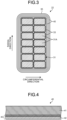
- FIG. 2 is a perspective view illustrating a configuration of the insulating coil 22 according to the embodiment.
- FIG. 3 is a cross-sectional view illustrating a configuration of the insulating coil 22 according to the embodiment.
- the insulating coil 22 includes a laminated conductor 31 (conductor), a turn insulating portion 33, and a main insulating portion 35.
- the turn insulating portion 33 and the main insulating portion 35 constitute an insulating structure of the insulating coil 22.
- the laminated conductor 31 is formed by laminating a plurality of conducting wires 31A.
- the laminated conductor 31 according to the present embodiment is configured by bundling 14 (the number of lamination: 7, the number of columns: 2) conducting wires 31A. Note that the configuration of the laminated conductor 31 is not limited thereto, and should be appropriately designed according to the use situation.
- the laminated conductor 31 may include, for example, more than 14 conducting wires 31A, or may be configured by laminating only one conducting wire 31A.
- the turn insulating portion 33 is provided on an outer face of each conducting wire 31A. As a result, the outer face of the laminated conductor 31 is covered with the turn insulating portion 33.
- the main insulating portion 35 is provided outside the turn insulating portion 33.
- the main insulating portion 35 is configured by winding a main insulating tape 40 (tape-shaped member).
- the main insulating tape 40 according to the present embodiment is spirally wound by a half lap method.
- the width of the main insulating tape 40 is W
- the pitch of the spiral is W/2. That is, the main insulating tape 40 is wound so as to overlap a half of the main insulating tape 40 wound in the previous turn.
- the main insulating tape 40 may be wound so as to be further superimposed thereon.
- the main insulating tape 40 can be formed in a multilayer shape. As the number of layers of the main insulating tape 40 increases, the insulating performance can be improved.
- the number of windings of the main insulating tape 40 may be appropriately selected according to required insulating performance and the like.
- FIG. 4 is a cross-sectional view schematically illustrating a configuration of the main insulating tape 40 according to the embodiment.
- Main insulating tape 40 includes a main insulating layer 41, a fiber reinforced layer 42, and a polymer layer 43.
- the main insulating layer 41 is made of a non-conductive material, and is a main portion for realizing an insulating function of the main insulating tape 40.
- the fiber reinforced layer 42 is a portion that supports the main insulating layer 41 and has a function of securing strength of the main insulating tape 40 as a whole.
- the polymer layer 43 is a portion that includes a bonding polymer, penetrates the fiber reinforced layer 42, and has a function of bonding the fiber reinforced layer 42 and the main insulating layer 41.
- the main insulating layer 41 includes, for example, an inorganic material such as mica, asbestos, or a ceramic powder as a main component.
- the fiber reinforced layer 42 includes, for example, glass fiber, polyester fiber, or the like as a main component, and is usually woven in a mesh shape.
- the fiber reinforced layer 42 is not limited to fibers, and may be formed as a nonwoven fabric or may be formed of a polymer film such as polyester or polyimide.
- the polymer layer 43 includes, for example, an unsaturated polyester resin, an epoxy resin, a polyimide resin, or the like as a main component.
- the thickness of the main insulating layer 41 is, for example, about 100 um.
- the thickness of the fiber reinforced layer 42 is thinner than that of the main insulating layer 41, and is, for example, about 30 um or less in many cases.
- the polymer layer 43 is illustrated as a constituent element of the main insulating tape 40, but since the polymer layer 43 penetrates the fiber reinforced layer 42, the polymer layer 43 has almost no thickness. Therefore, the main insulating layer 41 and the fiber reinforced layer 42 are usually almost in contact with each other.
- the main insulating tape 40 is wound with the main insulating layer 41 facing the laminated conductor 31 to be insulated and the fiber reinforced layer 42 facing outward, but in some cases, the other way around.
- FIG. 5 is a cross-sectional view schematically illustrating an internal structure of the main insulating portion 35 according to the embodiment.
- FIG. 5 illustrates a cross section along the longitudinal direction of the laminated conductor 31 (conducting wires 31A).
- FIG. 5 illustrates a case where main insulating tape 40 is wound twice, and the main insulating portion 35 includes a taping layer A formed by a first time winding and a taping layer B formed by a second time winding.
- the main insulating portion 35 includes the main insulating layer 41 and an impregnated portion 50.
- the main insulating layers 41 adjacent to each other in the longitudinal direction overlap each other by a half of the width. This is due to the winding method of the half lap method.
- the impregnated portion 50 is a portion formed by permeation of a resin including a nanofiller 55 into or around the polymer layer 43 that joins the main insulating layer 41 and the fiber reinforced layer 42.
- the thickness of the main insulating layer 41 is expressed to be thin, and the line indicating the fiber reinforced layer 42 is omitted.
- the periphery of the main insulating layer 41 is covered with the impregnated portion 50 (polymer layer 43) in which the nanofiller 55 is dispersed. Further, the resin including the nanofiller 55 also penetrates the main insulating layer 41, but the expression thereof is omitted in FIG. 5 .
- the nanofiller 55 includes non-conductive nano-order particles, for example, particles including a metal oxide.
- the particle size of the nanofiller 55 is preferably 50 nm or less. Specific examples of the substance constituting the nanofiller 55 will be described later.
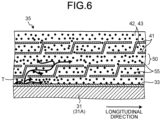
- FIG. 6 is a cross-sectional view schematically illustrating the effect of the nanofiller 55 according to the embodiment.
- FIG. 6 illustrates a state in which the electric tree T is generated in the impregnated portion 50.
- the electric tree T is an electrical deterioration phenomenon caused by a voltage applied to the laminated conductor 31 and the stator 20.
- the electric tree T develops and reaches the surface layer portion of the main insulating portion 35, dielectric breakdown occurs, and the rotary electric machine 1 stops its operation.
- the nanofiller 55 dispersed in the impregnated portion 50 has a development suppressing effect of suppressing the linear development of the electric tree T and reducing the development speed of the electric tree T.
- the insulating performance of the main insulating portion 35 can be improved.
- Such a development suppressing effect changes not only depending on the content of the nanofiller 55 but also strongly depending on dispersiveness.
- the development suppressing effect increases as dispersiveness (uniformity of dispersion) of the nanofiller 55 in the impregnated portion 50 increases. Therefore, in order to improve the development suppressing effect (insulating performance), it is important to use a resin having high dispersiveness of the nanofiller 55.
- FIG. 7 is a flowchart illustrating a procedure in the method of producing the insulating structure of the insulating coil 22 according to the embodiment.
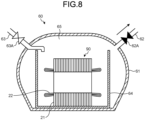
- FIG. 8 is a diagram illustrating a state in the first half stage of an impregnation device 60 used in the method of producing the insulating structure according to the embodiment.
- FIG. 9 is a diagram illustrating a state in the second half stage of the impregnation device 60 used in the method of producing the insulating structure according to the embodiment.
- the main insulating tape 40 is wound around the laminated conductor 31 (see FIG. 2 ), and the insulating coil 22 before resin impregnation is formed (S101). Thereafter, the insulating coil 22 before resin impregnation is inserted into the stator core 21 and assembled to form a stator unit 90 (see FIG. 8 ) (S102). Thereafter, the stator unit 90 is installed in the impregnation device 60 (S103), and the inside of the impregnation device 60 is evacuated (S104).
- the impregnation device 60 includes a container 61, an exhaust pipe 62, an exhaust valve 62A, a supply pipe 63, a supply valve 63A, and a treatment tank 64.
- the stator unit 90 is installed in the treatment tank 64 placed in the container 61.
- vacuum is produced in the container 61.
- the supply valve 63A is closed, and air in the container 61 is sucked by a suction device connected to the exhaust pipe 62.
- the inside of the insulating coil 22 is in a vacuum state even in the space in the turn insulating portion 33 and the main insulating tape 40 wound around the turn insulating portion.
- the stator unit 90 in the treatment tank 64 is immersed in a resin 47 (S105).
- the exhaust valve 62A is closed, and the resin 47 is supplied from the supply pipe 63 into the treatment tank 64.
- the resin 47 is supplied so that the entire stator unit 90 is immersed.
- the pressure in the impregnation device 60 (container 61) is increased (S106). As illustrated in FIG. 9 , the increasing the pressure is performed by opening the supply valve 63A and supplying a pressurized gas 65 from the supply pipe 63 into the container 61.
- the pressurized gas 65 is preferably a substance that does not react with the resin 47, and is preferably an inert gas such as nitrogen gas or dry air.
- Increasing the pressure in the container 61 causes the resin 47 including the nanofiller 55 to be impregnated into the turn insulating portion 33 and the main insulating tape 40 of the insulating coil 22.
- the stator unit 90 is taken out from the impregnation device 60 (S107), and the resin 47 impregnated in the insulating coil 22 including the main insulating tape 40 is solidified (S108).
- the method of solidifying the resin 47 is determined according to the properties of the epoxy resin to be used. For example, when a thermosetting epoxy resin is used, a method of housing the stator unit 90 in a drying furnace having a predetermined temperature for a predetermined time is performed, and the stator 20 is finally obtained (see FIG. 1 ). Thereafter, the stator 20 is attached to the frame 6 constituting the outer frame. Depending on the specifications of the rotary electric machine 1, the insulating coil 22 may be assembled in the stator core 21 previously attached to the frame 6. In this case, the assembly of the frame 6, the stator core 21, and the insulating coil 22 is treated as the stator unit 90.
- the resin 47 according to the present embodiment is a composition produced by mixing an epoxy resin, the nanofiller 55, a reactive diluent, and an acid anhydride-based curing agent (curing agent).
- the epoxy resin includes a compound which includes two or more three-membered rings composed of two carbon atoms and one oxygen atom in one molecule and can be cured.
- the epoxy resin includes, for example, a bisphenol A type epoxy resin, an alicyclic epoxy resin, a bisphenol F type epoxy resin, a biphenyl type epoxy resin, a naphthalene type epoxy resin, a novolac type epoxy resin, a phenol novolac type epoxy resin, or the like as a main component.
- the epoxy resin may include these compounds singly or in combination of two or more kinds thereof.
- the epoxy resin preferably includes an alicyclic epoxy resin from the viewpoint of chemical affinity with the reactive diluent.
- the nanofiller 55 includes a non-conductive metal oxide or the like.
- the nanofiller 55 includes, for example, alumina, silica, titanium oxide, magnesium oxide, bismuth trioxide, cerium dioxide, cobalt monoxide, copper oxide, iron trioxide, holmium oxide, indium oxide, manganese oxide, tin oxide, yttrium oxide, zinc oxide, or the like as a main component.
- the nanofiller 55 may include these compounds singly, or in combination of two or more kinds thereof.
- the surface of the nanofiller 55 may be modified with a coupling agent for the purpose of improving dispersiveness in an epoxy resin, preventing re-aggregation, improving adhesiveness, and the like.
- the reactive diluent reduces the viscosity of the epoxy resin by reacting with the epoxy resin.
- the reactive diluent includes a compound that can be part of the skeleton in the cured product of the thermosetting resin composition by having a reactive group in the molecular skeleton.
- the reactive diluent includes, for example, butyl glycidyl ether, 1,4-butanediol diglycidyl ether, alkylene monoglycidyl ether, alkylphenol monoglycidyl ether, polypropylene glycol diglycidyl ether, alkylene diglycidyl ether, neopentyl glycol diglycidyl ether, 1,6-hexanediol diglycidyl ether, 1,12 dodecanediol diglycidyl ether, o-cresyl glycidyl ether, 1,2-epoxytetradecane, or the like as a main component.
- the reactive diluent may include these compounds singly or in combination of two or more thereof.
- the epoxy resin includes an alicyclic epoxy resin
- the reactive diluent preferably includes butyl glycidyl ether.
- the acid anhydride-based curing agent includes, for example, 4-methylhexahydrophthalic anhydride, hexahydrophthalic anhydride, tetrahydrophthalic anhydride, 4-methyltetrahydrophthalic anhydride, tetrabromophthalic anhydride, nadic anhydride, methyl nadic anhydride, trimellitic anhydride, pyromellitic anhydride, methylhymic anhydride, or the like as a main component.
- the acid anhydride-based curing agent may include these compounds singly or in combination of two or more kinds thereof.
- a curing accelerator may be used to accelerate the reaction in the step of solidifying (curing) the resin 47 in a drying furnace or the like.
- the curing accelerator includes, for example, a compound capable of accelerating the crosslinking reaction between the epoxy compound and the acid anhydride-based curing agent.
- the curing accelerator includes, for example, a metal chelate compound, an ammonium ion compound, an imidazole compound, or the like as a main component.
- the curing accelerator may include these compounds singly or in combination of two or more kinds thereof.
- the resin 47 includes, for example, an epoxy resin, a nanofiller 55, a reactive diluent, and an acid anhydride-based curing agent in the following proportions.
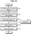
- FIG. 10 is a flowchart illustrating a procedure in the method of producing the resin 47 according to the embodiment.
- the nanofiller 55 at a ratio of 15 wt% or more is mixed with the epoxy resin (filler mixing step: S201).
- the ratio (15 wt% or more) is a ratio of the weight of the nanofiller 55 to the weight of the epoxy resin.
- the filler mixing step is preferably performed so that the mixture produced in this step has a viscosity of 100 P (poise: dPaDs) or more.
- the nanofiller 55 at a ratio of the predetermined value (15 wt%) or more is mixed with the epoxy resin to generate a mixture having a viscosity of the predetermined value (100 P) or more.
- shear mixing step S202
- Shear mixing of the mixture can be performed better when the viscosity is relatively high than when the viscosity is relatively low.
- the shear mixing step is performed using an appropriate apparatus capable of generating a shear stress in the mixture, and is performed using, for example, a three-roll mill mixer, a planetary mixer (planetary stirrer), a LABO PLASTOMILL mixer (registered trademark), a Miracle KCK mixer (registered trademark), or the like.
- the reactive diluent is mixed with the mixture subjected to shear mixing and stirred (diluent mixing step: S203).
- the diluent mixing step is preferably performed so that the viscosity of the mixture (composition) produced in this step is less than 10 P.
- the stirring in the diluent mixing step can be performed using an appropriate apparatus capable of high-speed stirring, and is performed using, for example, a disper mixer, a concentric biaxial mixer, a planetary mixer, a bead mill mixer, or the like.
- the dispersiveness of the nanofiller 55 is evaluated on the mixture with less than 10 P produced by the diluent mixing step (S203) (dispersiveness evaluation step: S210).
- a method of evaluating the dispersiveness of the nanofiller 55 for example, there is a method of irradiating the mixture with a laser pointer. Since the nanofiller 55 in the mixture scatters the light of the laser pointer (Tyndall phenomenon), when the laser pointer is directed toward the mixture, a trajectory of light may appear in the mixture.
- the mixture when the mixture is irradiated with red light having a wavelength of 635 nm to 690 nm, in a case where the particle size of the nanofiller 55 is larger than the wavelength, a trajectory of light clearly appears in the mixture.
- the particle diameter of the nanofiller 55 is smaller than the wavelength, the trajectory of light is hardly visible. Therefore, it can be evaluated that the dispersiveness of the nanofiller 55 in the mixture is higher as the luminosity of the trajectory of light appearing in the mixture is lower.
- the mixture generated through steps S201 to S203 is irradiated with red light, the trajectory of light in the mixture is hardly visible, and the luminous intensity is extremely low.
- the method using a laser pointer is simple and convenient, while various particle size measurement devices that measure the particle size of the nanofiller 55 from Brownian motion or the like in the mixture may be used.
- the acid anhydride curing agent is mixed with the mixture of less than 10 P generated by the diluent mixing step (S203), and the mixture is stirred (curing agent mixing step: S204).
- the acid anhydride curing agent is mixed with the same extent with the epoxy resin used in terms of chemical equivalents.
- a curing accelerator catalyst
- the curing agent mixing step is performed so that the composition has a predetermined viscosity (for example, a viscosity practically suitable as the resin 47 for impregnation).
- the stirring in the curing agent mixing step can be performed using the device similar to that in the diluent mixing step (S203).
- the curing agent mixing step (S204) may be performed when the dispersiveness of the nanofiller 55 is evaluated to satisfy a predetermined criterion in the dispersiveness evaluation step (S210).
- step S104 may be performed in a case where the luminosity of the trajectory of light appearing in the mixture in a method using a laser pointer is equal to or less than a threshold value.
- the mixture generated by the curing agent mixing step (S204) is collected (S205).
- the collected mixture is used as the resin 47 for impregnation as described above.
- the resin 47 in which the nanofiller 55 is dispersed with high dispersiveness can be produced.
- the effect of suppressing the development of the electric tree T by the nanofiller 55 (insulating performance) can be improved.
- the viscosity of the resin 47 can be stabilized over a long period of time, and the pot life of the resin 47 can be improved.
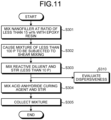
- FIG. 11 is a flowchart illustrating a procedure in a method of producing a resin according to the first comparative example.
- the proportion of the nanofiller to be mixed with the epoxy resin is made smaller than that in the above embodiment.
- the nanofiller at a ratio of less than 15 wt% is mixed with an epoxy resin (S301).
- the viscosity of the mixture produced by this step will be less than 100 P.
- the reactive diluent is mixed with the mixture subjected to shear mixing and stirred (S303).
- the step is performed such that the viscosity of the mixture is less than 10 P.
- the method of mixing and stirring here is similar to that in step S203 in the above embodiment.
- the dispersiveness of the nanofiller is evaluated on the mixture of less than 10 P produced in step S303 (S310).
- the evaluation method here is similar to that in step S210 in the above embodiment.
- the mixture generated through steps S301 to S303 is irradiated with red light, the trajectory of light in the mixture is clearly visible, and the luminous intensity is relatively high. This is because, since the mixing ratio of the nanofiller is set to less than 15 wt% in step S301, as described above, the viscosity of the mixture is less than 100 P, and a high shear stress is not applied to the mixture.
- step S303 the acid anhydride curing agent is mixed with the mixture of less than 10 P generated in step S303, and the mixture is stirred (curing agent mixing step: S304).
- the method of mixing and stirring here is similar to that in step S204 in the above embodiment.
- step S304 Thereafter, the mixture generated in step S304 is collected (S305).
- FIG. 12 is a flowchart illustrating a procedure in a method of producing a resin according to the second comparative example.
- the producing method according to the second comparative example produces a resin including no nanofiller.
- a reactive diluent is mixed with the epoxy resin and stirred (S401).
- the acid anhydride curing agent is mixed with the mixture generated in step S401, and the mixture is stirred (S402).
- step S402 the mixture generated in step S402 is collected (S403).
- the insulation life of the insulating structure impregnated with the resin produced by each of the production methods of the above-described embodiment, the first comparative example, and the second comparative example is evaluated.
- FIG. 13 is a diagram illustrating a test method of the insulation life.
- test piece 101 impregnated with the resin 47 according to the embodiment a test piece 102 impregnated with the resin according to the first comparative example, and a test piece 103 impregnated with the resin according to the second comparative example are prepared.
- Each test piece 101 to 103 is obtained by sandwiching a needle-shaped electrode 111 between several tens of mica tapes stacked, and bringing an end of the mica tape into contact with a ground electrode 113.
- the mica tape of the leftmost test piece 101 is pressure-impregnated with the resin 47 according to the embodiment and thermally cured.
- the mica tape of the center test piece 102 is pressure-impregnated with the resin according to the first comparative example and thermally cured.
- the mica tape of the test piece 103 at the right end is pressure-impregnated with the resin according to the second comparative example and thermally cured.
- a high voltage is applied from the voltage generator 112 to each electrode 111, and the time until each test piece 101 to 103 reached the dielectric breakdown is measured.
- FIG. 14 is a graph illustrating a comparison result of the time until the insulating structure reaches the dielectric breakdown in the embodiment, the first comparative example, and the second comparative example.
- the value on the vertical axis illustrated in FIG. 14 is a relative value when the value of the second comparative example is one. As illustrated in FIG. 14 , the time until the insulating structure including the resin 47 according to the embodiment reaches the dielectric breakdown is 25 times or more longer than that the times according to the first comparative example and the second comparative example.
- the above results are attributed to the fact that the dispersiveness of the nanofiller 55 included in the resin 47 according to the embodiment is higher than that in the first comparative example.
- Such improvement of the dispersiveness of the nanofiller 55 is mainly realized by performing the filler mixing step (S101) and the shear mixing step (S102) described above. That is, first, the nanofiller 55 at a ratio of 15 wt% or more is mixed with the epoxy resin to produce a mixture having a viscosity of 100 P or more, and the dispersiveness of the nanofiller 55 can be finally greatly improved by a technique of causing the mixture having a high viscosity to be subjected to high shear mixing.
- the improvement of the dispersiveness of the nanofiller 55 realizes improvement of the viscosity stability of the resin 47 (suppression of viscosity increase with time).
- the resin 47 having high dispersiveness and high viscosity stability of the nanofiller 55. This makes it possible to efficiently produce a high-performance insulating structure.
Landscapes
- Engineering & Computer Science (AREA)
- Chemical & Material Sciences (AREA)
- Power Engineering (AREA)
- Organic Chemistry (AREA)
- Health & Medical Sciences (AREA)
- Chemical Kinetics & Catalysis (AREA)
- Medicinal Chemistry (AREA)
- Polymers & Plastics (AREA)
- Manufacturing & Machinery (AREA)
- Spectroscopy & Molecular Physics (AREA)
- Physics & Mathematics (AREA)
- Manufacture Of Motors, Generators (AREA)
- Insulation, Fastening Of Motor, Generator Windings (AREA)
- Processes Of Treating Macromolecular Substances (AREA)
- Epoxy Resins (AREA)
- Insulating Of Coils (AREA)
- Organic Insulating Materials (AREA)
- Insulating Bodies (AREA)
Abstract
Description
- The present invention relates to a method of producing a resin and a method of producing an insulating structure.
- A coil used in a rotary electric machine such as an electric motor or a generator is provided with an insulating structure that prevents a current flowing through a conductor in the coil from leaking to the outside.
- As the insulating structure as described above, a structure is known in which an insulating tape including mica or the like is wound around an outer peripheral portion of a conductor, and a space in the insulating tape is impregnated with a resin including a filler made of a metal oxide or the like. The filler functions to suppress the development of an electric tree generated in the insulating tape and improve the insulating performance.
-
- Patent Literature 1:
US 2013/0131218 A - Patent Literature 2:
JP 2006-246599 A - The effect of suppressing the development of the electric tree by the filler as described above largely depends on the dispersiveness of the filler. When the dispersiveness of the filler is low, the filler agglomerates in the insulating structure, and the region where the electric tree easily develops (region of only resin) increases, so that the effect of suppressing the development of the electric tree is reduced.
- The viscosity of the filler-including resin greatly affects the productivity of the insulating structure. For example, when the viscosity of the resin unintentionally increases, an operation of impregnating the insulating tape or the like with the resin is difficult.
- As described above, in order to efficiently produce a high-performance insulating structure, it is important to produce a resin having high dispersiveness and high viscosity stability of the filler.
- Therefore, an object of the present invention is to provide a method of producing a resin and a method of producing an insulating structure capable of efficiently producing a high-performance insulating structure.
- An aspect of the present invention is a method of producing a resin with which an insulating structure formed on an outer peripheral portion of a conductor is impregnated, the method including: a filler mixing step of mixing a nanofiller at a ratio of 15 wt% or more with an epoxy resin to form a mixture; a shear mixing step of causing the mixture to be subjected to shear mixing; a diluent mixing step of mixing a reactive diluent that reduces a viscosity of the epoxy resin, with the mixture after the shear mixing step; and a curing agent mixing step of mixing an acid anhydride curing agent with the mixture after the diluent mixing step.
-
-
FIG. 1 is a cross-sectional view illustrating a configuration of a rotary electric machine according to the embodiment; -
FIG. 2 is a perspective view illustrating a configuration of an insulating coil according to the embodiment; -
FIG. 3 is a cross-sectional view illustrating a configuration of an insulating coil according to the embodiment; -
FIG. 4 is a cross-sectional view schematically illustrating a configuration of a main insulating tape according to the embodiment; -
FIG. 5 is a cross-sectional view schematically illustrating an internal structure of a main insulating portion according to the embodiment; -
FIG. 6 is a cross-sectional view schematically illustrating an effect of a nanofiller according to the embodiment; -
FIG. 7 is a flowchart illustrating a procedure in the method of producing the insulating structure of the insulating coil according to the embodiment; -
FIG. 8 is a diagram illustrating a state in the first half stage of the impregnation device used in the method of producing the insulating structure according to the embodiment; -
FIG. 9 is a diagram illustrating a state in the second half stage of the impregnation device used in the method of producing the insulating structure according to the embodiment; -
FIG. 10 is a flowchart illustrating a procedure in the method of producing a resin according to the embodiment; -
FIG. 11 is a flowchart illustrating a procedure in a method of producing a resin according to the first comparative example; -
FIG. 12 is a flowchart illustrating a procedure in a method of producing a resin according to the second comparative example; -
FIG. 13 is a diagram illustrating a test method of an insulation life; and -
FIG. 14 is a graph illustrating a comparison result of the time until the insulating structure reaches the dielectric breakdown in the embodiment, the first comparative example, and the second comparative example. - Hereinafter, an embodiment of the present invention will be described with reference to the drawings. In the present specification, components according to the embodiment and descriptions of the components may be described in a plurality of expressions. The components and the description thereof are examples, and are not limited by the expression of the present specification. Components may also be identified with names different from those herein. In addition, the component may be described by an expression different from the expression in the present specification.
-
FIG. 1 is a cross-sectional view illustrating a configuration of a rotaryelectric machine 1 according to the embodiment. - The rotary
electric machine 1 includes arotor 10 and astator 20. The rotaryelectric machine 1 is a component such as an electric motor or a generator. - The
rotor 10 includes arotor shaft 11 and arotor core 12. Near both ends of therotor shaft 11 are rotatably and axially supported bybearings 5. Thebearing 5 is fixed to abearing bracket 7 provided integrally with aframe 6 constituting the outer frame of the rotaryelectric machine 1. Therotor core 12 is fixed to the outer peripheral face of therotor shaft 11 and rotates together with therotor shaft 11. - The
stator 20 includes astator core 21 and aninsulating coil 22. Thestator core 21 is disposed radially outward of therotor core 12 with a gap. Theinsulating coil 22 is a member that is incorporated in thestator core 21 and generates a magnetic field necessary for the rotaryelectric machine 1, and an insulating structure described later is provided on an outer peripheral portion thereof. Theinsulating coil 22 is assembled so as to penetrate thestator core 21. -
FIG. 2 is a perspective view illustrating a configuration of theinsulating coil 22 according to the embodiment.FIG. 3 is a cross-sectional view illustrating a configuration of theinsulating coil 22 according to the embodiment. - The
insulating coil 22 includes a laminated conductor 31 (conductor), aturn insulating portion 33, and a main insulatingportion 35. Theturn insulating portion 33 and the main insulatingportion 35 constitute an insulating structure of theinsulating coil 22. - The laminated
conductor 31 is formed by laminating a plurality of conductingwires 31A. The laminatedconductor 31 according to the present embodiment is configured by bundling 14 (the number of lamination: 7, the number of columns: 2) conductingwires 31A. Note that the configuration of the laminatedconductor 31 is not limited thereto, and should be appropriately designed according to the use situation. The laminatedconductor 31 may include, for example, more than 14 conductingwires 31A, or may be configured by laminating only one conductingwire 31A. - The
turn insulating portion 33 is provided on an outer face of each conductingwire 31A. As a result, the outer face of the laminatedconductor 31 is covered with theturn insulating portion 33. The main insulatingportion 35 is provided outside theturn insulating portion 33. The main insulatingportion 35 is configured by winding a main insulating tape 40 (tape-shaped member). - The main
insulating tape 40 according to the present embodiment is spirally wound by a half lap method. When the width of the main insulatingtape 40 is W, the pitch of the spiral is W/2. That is, the main insulatingtape 40 is wound so as to overlap a half of the main insulatingtape 40 wound in the previous turn. After one round of winding of thelaminated conductor 31 in the entire longitudinal direction is completed, the main insulatingtape 40 may be wound so as to be further superimposed thereon. As a result, the main insulatingtape 40 can be formed in a multilayer shape. As the number of layers of the main insulatingtape 40 increases, the insulating performance can be improved. The number of windings of the main insulatingtape 40 may be appropriately selected according to required insulating performance and the like. -
FIG. 4 is a cross-sectional view schematically illustrating a configuration of the main insulatingtape 40 according to the embodiment. -
Main insulating tape 40 includes a main insulatinglayer 41, a fiber reinforcedlayer 42, and apolymer layer 43. - The main insulating
layer 41 is made of a non-conductive material, and is a main portion for realizing an insulating function of the main insulatingtape 40. The fiber reinforcedlayer 42 is a portion that supports the main insulatinglayer 41 and has a function of securing strength of the main insulatingtape 40 as a whole. Thepolymer layer 43 is a portion that includes a bonding polymer, penetrates the fiber reinforcedlayer 42, and has a function of bonding the fiber reinforcedlayer 42 and the main insulatinglayer 41. - The main insulating
layer 41 includes, for example, an inorganic material such as mica, asbestos, or a ceramic powder as a main component. The fiber reinforcedlayer 42 includes, for example, glass fiber, polyester fiber, or the like as a main component, and is usually woven in a mesh shape. In addition, the fiber reinforcedlayer 42 is not limited to fibers, and may be formed as a nonwoven fabric or may be formed of a polymer film such as polyester or polyimide. Thepolymer layer 43 includes, for example, an unsaturated polyester resin, an epoxy resin, a polyimide resin, or the like as a main component. - The thickness of the main insulating
layer 41 is, for example, about 100 um. The thickness of the fiber reinforcedlayer 42 is thinner than that of the main insulatinglayer 41, and is, for example, about 30 um or less in many cases. InFIG. 4 , thepolymer layer 43 is illustrated as a constituent element of the main insulatingtape 40, but since thepolymer layer 43 penetrates the fiber reinforcedlayer 42, thepolymer layer 43 has almost no thickness. Therefore, the main insulatinglayer 41 and the fiber reinforcedlayer 42 are usually almost in contact with each other. Usually, the main insulatingtape 40 is wound with the main insulatinglayer 41 facing thelaminated conductor 31 to be insulated and the fiber reinforcedlayer 42 facing outward, but in some cases, the other way around. -
FIG. 5 is a cross-sectional view schematically illustrating an internal structure of the main insulatingportion 35 according to the embodiment. -
FIG. 5 illustrates a cross section along the longitudinal direction of the laminated conductor 31 (conductingwires 31A).FIG. 5 illustrates a case where main insulatingtape 40 is wound twice, and the main insulatingportion 35 includes a taping layer A formed by a first time winding and a taping layer B formed by a second time winding. - The main insulating
portion 35 includes the main insulatinglayer 41 and an impregnatedportion 50. In each of the taping layer A and the taping layer B, the main insulatinglayers 41 adjacent to each other in the longitudinal direction overlap each other by a half of the width. This is due to the winding method of the half lap method. - The impregnated
portion 50 is a portion formed by permeation of a resin including ananofiller 55 into or around thepolymer layer 43 that joins the main insulatinglayer 41 and the fiber reinforcedlayer 42. InFIG. 5 , in order to emphasize the fiber reinforcedlayer 42 or thepolymer layer 43 formed by penetrating around the fiber reinforced layer, the thickness of the main insulatinglayer 41 is expressed to be thin, and the line indicating the fiber reinforcedlayer 42 is omitted. As illustrated inFIG. 5 , the periphery of the main insulatinglayer 41 is covered with the impregnated portion 50 (polymer layer 43) in which thenanofiller 55 is dispersed. Further, the resin including thenanofiller 55 also penetrates the main insulatinglayer 41, but the expression thereof is omitted inFIG. 5 . - The
nanofiller 55 includes non-conductive nano-order particles, for example, particles including a metal oxide. The particle size of thenanofiller 55 is preferably 50 nm or less. Specific examples of the substance constituting thenanofiller 55 will be described later. -
FIG. 6 is a cross-sectional view schematically illustrating the effect of thenanofiller 55 according to the embodiment. -
FIG. 6 illustrates a state in which the electric tree T is generated in the impregnatedportion 50. The electric tree T is an electrical deterioration phenomenon caused by a voltage applied to thelaminated conductor 31 and thestator 20. When the electric tree T develops and reaches the surface layer portion of the main insulatingportion 35, dielectric breakdown occurs, and the rotaryelectric machine 1 stops its operation. - The
nanofiller 55 dispersed in the impregnatedportion 50 has a development suppressing effect of suppressing the linear development of the electric tree T and reducing the development speed of the electric tree T. Thus, the insulating performance of the main insulatingportion 35 can be improved. Such a development suppressing effect changes not only depending on the content of thenanofiller 55 but also strongly depending on dispersiveness. The development suppressing effect increases as dispersiveness (uniformity of dispersion) of thenanofiller 55 in the impregnatedportion 50 increases. Therefore, in order to improve the development suppressing effect (insulating performance), it is important to use a resin having high dispersiveness of thenanofiller 55. -
FIG. 7 is a flowchart illustrating a procedure in the method of producing the insulating structure of the insulatingcoil 22 according to the embodiment.FIG. 8 is a diagram illustrating a state in the first half stage of animpregnation device 60 used in the method of producing the insulating structure according to the embodiment.FIG. 9 is a diagram illustrating a state in the second half stage of theimpregnation device 60 used in the method of producing the insulating structure according to the embodiment. - First, the main insulating
tape 40 is wound around the laminated conductor 31 (seeFIG. 2 ), and the insulatingcoil 22 before resin impregnation is formed (S101). Thereafter, the insulatingcoil 22 before resin impregnation is inserted into thestator core 21 and assembled to form a stator unit 90 (seeFIG. 8 ) (S102). Thereafter, thestator unit 90 is installed in the impregnation device 60 (S103), and the inside of theimpregnation device 60 is evacuated (S104). - As illustrated in
FIG. 8 , theimpregnation device 60 includes acontainer 61, anexhaust pipe 62, anexhaust valve 62A, asupply pipe 63, asupply valve 63A, and atreatment tank 64. In step S103, thestator unit 90 is installed in thetreatment tank 64 placed in thecontainer 61. Thereafter, in step S104, vacuum is produced in thecontainer 61. When evacuation is performed, thesupply valve 63A is closed, and air in thecontainer 61 is sucked by a suction device connected to theexhaust pipe 62. As a result, the inside of the insulatingcoil 22 is in a vacuum state even in the space in theturn insulating portion 33 and the main insulatingtape 40 wound around the turn insulating portion. - After the producing the vacuum is performed as described above, as illustrated in
FIG. 9 , thestator unit 90 in thetreatment tank 64 is immersed in a resin 47 (S105). At this time, theexhaust valve 62A is closed, and theresin 47 is supplied from thesupply pipe 63 into thetreatment tank 64. Theresin 47 is supplied so that theentire stator unit 90 is immersed. - After the
stator unit 90 is immersed in theresin 47 as described above, the pressure in the impregnation device 60 (container 61) is increased (S106). As illustrated inFIG. 9 , the increasing the pressure is performed by opening thesupply valve 63A and supplying apressurized gas 65 from thesupply pipe 63 into thecontainer 61. Thepressurized gas 65 is preferably a substance that does not react with theresin 47, and is preferably an inert gas such as nitrogen gas or dry air. Increasing the pressure in thecontainer 61 causes theresin 47 including thenanofiller 55 to be impregnated into theturn insulating portion 33 and the main insulatingtape 40 of the insulatingcoil 22. - Thereafter, the
stator unit 90 is taken out from the impregnation device 60 (S107), and theresin 47 impregnated in the insulatingcoil 22 including the main insulatingtape 40 is solidified (S108). The method of solidifying theresin 47 is determined according to the properties of the epoxy resin to be used. For example, when a thermosetting epoxy resin is used, a method of housing thestator unit 90 in a drying furnace having a predetermined temperature for a predetermined time is performed, and thestator 20 is finally obtained (seeFIG. 1 ). Thereafter, thestator 20 is attached to theframe 6 constituting the outer frame. Depending on the specifications of the rotaryelectric machine 1, the insulatingcoil 22 may be assembled in thestator core 21 previously attached to theframe 6. In this case, the assembly of theframe 6, thestator core 21, and the insulatingcoil 22 is treated as thestator unit 90. - Hereinafter, a method of producing the
resin 47 impregnated into the main insulatingtape 40 will be described. As described above, in order to improve the effect of suppressing the development of the electric tree T by the nanofiller 55 (insulating performance of the main insulating portion 35), it is necessary to form the impregnatedportion 50 in which thenanofiller 55 is dispersed with high dispersiveness (uniformity) in the main insulatingtape 40. In order to form such an impregnatedportion 50, it is important to produce and use theresin 47 having high dispersiveness of thenanofiller 55. - The
resin 47 according to the present embodiment is a composition produced by mixing an epoxy resin, thenanofiller 55, a reactive diluent, and an acid anhydride-based curing agent (curing agent). - The epoxy resin includes a compound which includes two or more three-membered rings composed of two carbon atoms and one oxygen atom in one molecule and can be cured. The epoxy resin includes, for example, a bisphenol A type epoxy resin, an alicyclic epoxy resin, a bisphenol F type epoxy resin, a biphenyl type epoxy resin, a naphthalene type epoxy resin, a novolac type epoxy resin, a phenol novolac type epoxy resin, or the like as a main component. The epoxy resin may include these compounds singly or in combination of two or more kinds thereof. Specifically, the epoxy resin preferably includes an alicyclic epoxy resin from the viewpoint of chemical affinity with the reactive diluent.
- The
nanofiller 55 includes a non-conductive metal oxide or the like. Thenanofiller 55 includes, for example, alumina, silica, titanium oxide, magnesium oxide, bismuth trioxide, cerium dioxide, cobalt monoxide, copper oxide, iron trioxide, holmium oxide, indium oxide, manganese oxide, tin oxide, yttrium oxide, zinc oxide, or the like as a main component. Thenanofiller 55 may include these compounds singly, or in combination of two or more kinds thereof. The surface of thenanofiller 55 may be modified with a coupling agent for the purpose of improving dispersiveness in an epoxy resin, preventing re-aggregation, improving adhesiveness, and the like. - The reactive diluent reduces the viscosity of the epoxy resin by reacting with the epoxy resin. The reactive diluent includes a compound that can be part of the skeleton in the cured product of the thermosetting resin composition by having a reactive group in the molecular skeleton. The reactive diluent includes, for example, butyl glycidyl ether, 1,4-butanediol diglycidyl ether, alkylene monoglycidyl ether, alkylphenol monoglycidyl ether, polypropylene glycol diglycidyl ether, alkylene diglycidyl ether, neopentyl glycol diglycidyl ether, 1,6-hexanediol diglycidyl ether, 1,12 dodecanediol diglycidyl ether, o-cresyl glycidyl ether, 1,2-epoxytetradecane, or the like as a main component. The reactive diluent may include these compounds singly or in combination of two or more thereof. Specifically, when the epoxy resin includes an alicyclic epoxy resin, the reactive diluent preferably includes butyl glycidyl ether.
- The acid anhydride-based curing agent includes, for example, 4-methylhexahydrophthalic anhydride, hexahydrophthalic anhydride, tetrahydrophthalic anhydride, 4-methyltetrahydrophthalic anhydride, tetrabromophthalic anhydride, nadic anhydride, methyl nadic anhydride, trimellitic anhydride, pyromellitic anhydride, methylhymic anhydride, or the like as a main component. The acid anhydride-based curing agent may include these compounds singly or in combination of two or more kinds thereof.
- A curing accelerator may be used to accelerate the reaction in the step of solidifying (curing) the
resin 47 in a drying furnace or the like. The curing accelerator includes, for example, a compound capable of accelerating the crosslinking reaction between the epoxy compound and the acid anhydride-based curing agent. The curing accelerator includes, for example, a metal chelate compound, an ammonium ion compound, an imidazole compound, or the like as a main component. The curing accelerator may include these compounds singly or in combination of two or more kinds thereof. - The
resin 47 includes, for example, an epoxy resin, ananofiller 55, a reactive diluent, and an acid anhydride-based curing agent in the following proportions. - Epoxy resin: 30 wt% to 60 wt% (1)
- Acid anhydride-based curing agent: 30 wt% to 60 wt% (2)
- Reactive diluent: 5 wt% to 30 wt% (3)
- Nanofiller 55: 2 wt% to 30 wt% with respect to the entire mixture of (1) to (3)
-
FIG. 10 is a flowchart illustrating a procedure in the method of producing theresin 47 according to the embodiment. - First, the
nanofiller 55 at a ratio of 15 wt% or more is mixed with the epoxy resin (filler mixing step: S201). The ratio (15 wt% or more) is a ratio of the weight of thenanofiller 55 to the weight of the epoxy resin. The filler mixing step is preferably performed so that the mixture produced in this step has a viscosity of 100 P (poise: dPaDs) or more. As described above, in the method of producing theresin 47 according to the present embodiment, first, thenanofiller 55 at a ratio of the predetermined value (15 wt%) or more is mixed with the epoxy resin to generate a mixture having a viscosity of the predetermined value (100 P) or more. - Thereafter, the mixture of 100 P or more is subjected to shear mixing (shear mixing step: S202). Shear mixing of the mixture can be performed better when the viscosity is relatively high than when the viscosity is relatively low. The shear mixing step is performed using an appropriate apparatus capable of generating a shear stress in the mixture, and is performed using, for example, a three-roll mill mixer, a planetary mixer (planetary stirrer), a LABO PLASTOMILL mixer (registered trademark), a Miracle KCK mixer (registered trademark), or the like.
- Thereafter, the reactive diluent is mixed with the mixture subjected to shear mixing and stirred (diluent mixing step: S203). The diluent mixing step is preferably performed so that the viscosity of the mixture (composition) produced in this step is less than 10 P. The stirring in the diluent mixing step can be performed using an appropriate apparatus capable of high-speed stirring, and is performed using, for example, a disper mixer, a concentric biaxial mixer, a planetary mixer, a bead mill mixer, or the like.
- Here, the dispersiveness of the
nanofiller 55 is evaluated on the mixture with less than 10 P produced by the diluent mixing step (S203) (dispersiveness evaluation step: S210). As a method of evaluating the dispersiveness of thenanofiller 55, for example, there is a method of irradiating the mixture with a laser pointer. Since thenanofiller 55 in the mixture scatters the light of the laser pointer (Tyndall phenomenon), when the laser pointer is directed toward the mixture, a trajectory of light may appear in the mixture. For example, when the mixture is irradiated with red light having a wavelength of 635 nm to 690 nm, in a case where the particle size of thenanofiller 55 is larger than the wavelength, a trajectory of light clearly appears in the mixture. On the other hand, in a case where the particle diameter of thenanofiller 55 is smaller than the wavelength, the trajectory of light is hardly visible. Therefore, it can be evaluated that the dispersiveness of thenanofiller 55 in the mixture is higher as the luminosity of the trajectory of light appearing in the mixture is lower. When the mixture generated through steps S201 to S203 is irradiated with red light, the trajectory of light in the mixture is hardly visible, and the luminous intensity is extremely low. The method using a laser pointer is simple and convenient, while various particle size measurement devices that measure the particle size of the nanofiller 55 from Brownian motion or the like in the mixture may be used. - Thereafter, the acid anhydride curing agent is mixed with the mixture of less than 10 P generated by the diluent mixing step (S203), and the mixture is stirred (curing agent mixing step: S204). The acid anhydride curing agent is mixed with the same extent with the epoxy resin used in terms of chemical equivalents. At this time, as described above, a curing accelerator (catalyst) for accelerating the curing reaction between the epoxy resin and the acid anhydride curing agent may be added. The curing agent mixing step is performed so that the composition has a predetermined viscosity (for example, a viscosity practically suitable as the
resin 47 for impregnation). The stirring in the curing agent mixing step can be performed using the device similar to that in the diluent mixing step (S203). - The curing agent mixing step (S204) may be performed when the dispersiveness of the
nanofiller 55 is evaluated to satisfy a predetermined criterion in the dispersiveness evaluation step (S210). For example, step S104 may be performed in a case where the luminosity of the trajectory of light appearing in the mixture in a method using a laser pointer is equal to or less than a threshold value. - Thereafter, the mixture generated by the curing agent mixing step (S204) is collected (S205). The collected mixture is used as the
resin 47 for impregnation as described above. - By the above producing method, the
resin 47 in which thenanofiller 55 is dispersed with high dispersiveness can be produced. As a result, the effect of suppressing the development of the electric tree T by the nanofiller 55 (insulating performance) can be improved. In addition, due to the high dispersiveness of thenanofiller 55, the viscosity of theresin 47 can be stabilized over a long period of time, and the pot life of theresin 47 can be improved. - Hereinafter, a method of producing a resin according to the comparative example will be described.
-
FIG. 11 is a flowchart illustrating a procedure in a method of producing a resin according to the first comparative example. - In the production method according to the first comparative example, the proportion of the nanofiller to be mixed with the epoxy resin is made smaller than that in the above embodiment.
- First, the nanofiller at a ratio of less than 15 wt% is mixed with an epoxy resin (S301). The viscosity of the mixture produced by this step will be less than 100 P.
- Thereafter, the mixture of less than 100 P is subjected to shear mixing (S302). The method of shear mixing here is similar to that in step S202 in the above embodiment.
- Thereafter, the reactive diluent is mixed with the mixture subjected to shear mixing and stirred (S303). The step is performed such that the viscosity of the mixture is less than 10 P. The method of mixing and stirring here is similar to that in step S203 in the above embodiment.
- Here, the dispersiveness of the nanofiller is evaluated on the mixture of less than 10 P produced in step S303 (S310). The evaluation method here is similar to that in step S210 in the above embodiment. When the mixture generated through steps S301 to S303 is irradiated with red light, the trajectory of light in the mixture is clearly visible, and the luminous intensity is relatively high. This is because, since the mixing ratio of the nanofiller is set to less than 15 wt% in step S301, as described above, the viscosity of the mixture is less than 100 P, and a high shear stress is not applied to the mixture.
- Thereafter, the acid anhydride curing agent is mixed with the mixture of less than 10 P generated in step S303, and the mixture is stirred (curing agent mixing step: S304). The method of mixing and stirring here is similar to that in step S204 in the above embodiment.
- Thereafter, the mixture generated in step S304 is collected (S305).
-
FIG. 12 is a flowchart illustrating a procedure in a method of producing a resin according to the second comparative example. - The producing method according to the second comparative example produces a resin including no nanofiller.
- First, a reactive diluent is mixed with the epoxy resin and stirred (S401).
- Thereafter, the acid anhydride curing agent is mixed with the mixture generated in step S401, and the mixture is stirred (S402).
- Thereafter, the mixture generated in step S402 is collected (S403).
- Hereinafter, the insulation life of the insulating structure impregnated with the resin produced by each of the production methods of the above-described embodiment, the first comparative example, and the second comparative example is evaluated.
-
FIG. 13 is a diagram illustrating a test method of the insulation life. - First, a
test piece 101 impregnated with theresin 47 according to the embodiment, atest piece 102 impregnated with the resin according to the first comparative example, and atest piece 103 impregnated with the resin according to the second comparative example are prepared. Eachtest piece 101 to 103 is obtained by sandwiching a needle-shapedelectrode 111 between several tens of mica tapes stacked, and bringing an end of the mica tape into contact with aground electrode 113. The mica tape of theleftmost test piece 101 is pressure-impregnated with theresin 47 according to the embodiment and thermally cured. The mica tape of thecenter test piece 102 is pressure-impregnated with the resin according to the first comparative example and thermally cured. The mica tape of thetest piece 103 at the right end is pressure-impregnated with the resin according to the second comparative example and thermally cured. A high voltage is applied from thevoltage generator 112 to eachelectrode 111, and the time until eachtest piece 101 to 103 reached the dielectric breakdown is measured. -
FIG. 14 is a graph illustrating a comparison result of the time until the insulating structure reaches the dielectric breakdown in the embodiment, the first comparative example, and the second comparative example. - The value on the vertical axis illustrated in
FIG. 14 is a relative value when the value of the second comparative example is one. As illustrated inFIG. 14 , the time until the insulating structure including theresin 47 according to the embodiment reaches the dielectric breakdown is 25 times or more longer than that the times according to the first comparative example and the second comparative example. - The above results are attributed to the fact that the dispersiveness of the
nanofiller 55 included in theresin 47 according to the embodiment is higher than that in the first comparative example. Such improvement of the dispersiveness of thenanofiller 55 is mainly realized by performing the filler mixing step (S101) and the shear mixing step (S102) described above. That is, first, thenanofiller 55 at a ratio of 15 wt% or more is mixed with the epoxy resin to produce a mixture having a viscosity of 100 P or more, and the dispersiveness of thenanofiller 55 can be finally greatly improved by a technique of causing the mixture having a high viscosity to be subjected to high shear mixing. The improvement of the dispersiveness of thenanofiller 55 realizes improvement of the viscosity stability of the resin 47 (suppression of viscosity increase with time). - As described above, according to the present embodiment, it is possible to produce the
resin 47 having high dispersiveness and high viscosity stability of thenanofiller 55. This makes it possible to efficiently produce a high-performance insulating structure. - The above-described embodiment of the present invention does not limit the scope of the invention, and is merely an example included in the scope of the invention. In an embodiment of the present invention, for example, at least part of the specific application, structure, shape, operation, and effect may be changed, omitted, or added to the above-described embodiment without departing from the gist of the invention.
-
- 1 rotary electric machine
- 5 bearing
- 6 frame
- 7 bearing bracket
- 10 rotor
- 11 rotor shaft
- 12 rotor core
- 20 stator
- 21 stator core
- 22 insulating coil
- 31 laminated conductor (conductor)
- 31A conducting wire
- 33 turn insulating portion
- 35 main insulating portion
- 40 main insulating tape (tape-shaped member)
- 41 main insulating layer
- 42 fiber reinforced layer
- 43 polymer layer
- 47 resin
- 50 impregnated portion
- 55 nanofiller
- 60 impregnation device
- 61 container
- 62 exhaust pipe
- 62A exhaust valve
- 63 supply pipe
- 63A supply valve
- 64 treatment tank
- 65 pressurized gas
- 90 stator unit
- 101 to 103 test piece
- 111 electrode
- 112 voltage generator
- 113 ground electrode
- T electric tree
Claims (7)
- A method of producing a resin with which an insulating structure formed on an outer peripheral portion of a conductor is impregnated, the method comprising:a filler mixing step of mixing a nanofiller at a ratio of 15 wt% or more with an epoxy resin to form a mixture;a shear mixing step of causing the mixture to be subjected to shear mixing;a diluent mixing step of mixing a reactive diluent that reduces a viscosity of the epoxy resin, with the mixture after the shear mixing step; anda curing agent mixing step of mixing an acid anhydride curing agent with the mixture after the diluent mixing step.
- The method of producing a resin according to claim 1, wherein
the mixture after the filler mixing step has a viscosity of 100 P or more. - The method of producing a resin according to claim 2, wherein
the mixture after the diluent mixing step has a viscosity of 10 P or less. - The method of producing a resin according to any one of claims 1 to 3, the method further comprisinga dispersiveness evaluation step of evaluating dispersiveness of the nanofiller in the mixture after the diluent mixing step, and whereinthe curing agent mixing step is performed when dispersiveness of the nanofiller is evaluated to satisfy a predetermined criterion in the dispersiveness evaluation step.
- The method of producing a resin according to any one of claims 1 to 4, wherein
the epoxy resin includes an alicyclic epoxy resin. - The method of producing a resin according to claim 5, wherein
the reactive diluent includes butyl glycidyl ether. - A method of producing an insulating structure formed on an outer peripheral portion of a conductor, the method comprising:a resin production step of producing a resin including a nanofiller; anda step of impregnating a non-conductive tape-shaped member wound around the outer peripheral portion of the conductor with the resin, whereinthe resin production step includes:a filler mixing step of mixing the nanofiller at a ratio of 15 wt% or more with an epoxy resin to form a mixture;a shear mixing step of causing the mixture to be subjected to shear mixing;a diluent mixing step of mixing a reactive diluent that reduces a viscosity of the epoxy resin, with the mixture after the shear mixing step, anda curing agent mixing step of mixing an acid anhydride curing agent with the mixture after the diluent mixing step.
Applications Claiming Priority (2)
| Application Number | Priority Date | Filing Date | Title |
|---|---|---|---|
| JP2020146267A JP7308799B2 (en) | 2020-08-31 | 2020-08-31 | Resin manufacturing method and insulating structure manufacturing method |
| PCT/JP2020/048025 WO2022044358A1 (en) | 2020-08-31 | 2020-12-22 | Resin production method and insulating structure production method |
Publications (2)
| Publication Number | Publication Date |
|---|---|
| EP4206261A1 true EP4206261A1 (en) | 2023-07-05 |
| EP4206261A4 EP4206261A4 (en) | 2024-09-11 |
Family
ID=80355026
Family Applications (1)
| Application Number | Title | Priority Date | Filing Date |
|---|---|---|---|
| EP20940481.3A Pending EP4206261A4 (en) | 2020-08-31 | 2020-12-22 | RESIN PRODUCTION METHOD AND INSULATING STRUCTURE PRODUCTION METHOD |
Country Status (6)
| Country | Link |
|---|---|
| US (1) | US12168722B2 (en) |
| EP (1) | EP4206261A4 (en) |
| JP (1) | JP7308799B2 (en) |
| KR (1) | KR102690608B1 (en) |
| CN (1) | CN114502619B (en) |
| WO (1) | WO2022044358A1 (en) |
Families Citing this family (1)
| Publication number | Priority date | Publication date | Assignee | Title |
|---|---|---|---|---|
| JP7702374B2 (en) * | 2022-04-19 | 2025-07-03 | 株式会社Tmeic | Resin manufacturing method and insulating structure manufacturing method |
Family Cites Families (26)
| Publication number | Priority date | Publication date | Assignee | Title |
|---|---|---|---|---|
| TW538482B (en) * | 1999-04-26 | 2003-06-21 | Shinetsu Chemical Co | Semiconductor encapsulating epoxy resin composition and semiconductor device |
| JP2000344864A (en) * | 1999-06-09 | 2000-12-12 | Sumitomo Bakelite Co Ltd | Resin paste for semiconductor and semiconductor device sealed therewith |
| JP2003238771A (en) * | 2002-02-21 | 2003-08-27 | Toshiba Corp | Casting resin composition |
| US6919420B2 (en) * | 2002-12-05 | 2005-07-19 | International Business Machines Corporation | Acid-cleavable acetal and ketal based epoxy oligomers |
| JP4653443B2 (en) * | 2004-08-20 | 2011-03-16 | 株式会社東芝 | Resin composition for high voltage equipment, insulating material and insulating structure |
| JP2006246599A (en) | 2005-03-02 | 2006-09-14 | Toshiba Corp | Semiconductive tape, method for producing semiconductive tape, insulating coil, and rotating electric machine |
| JP2006249276A (en) * | 2005-03-11 | 2006-09-21 | Tokyo Electric Power Co Inc:The | Method for producing polymer-based nanocomposite |
| JP2008075069A (en) * | 2006-08-23 | 2008-04-03 | Toshiba Corp | Casting resin composition and insulating material and insulating structure using the same |
| CN101506301A (en) | 2006-08-23 | 2009-08-12 | 株式会社东芝 | Casting resin composition, and insulating material and insulating structure using same |
| JP2009013227A (en) * | 2007-07-02 | 2009-01-22 | Tokyo Electric Power Co Inc:The | Resin composition for electrical insulating material and method for producing the same |
| KR101072139B1 (en) * | 2009-04-07 | 2011-10-12 | 박재준 | Method for preparing epoxy/silica multicomposite for high voltage insulation and product thereby |
| EP2372725B1 (en) * | 2010-03-26 | 2013-09-11 | ABB Research Ltd. | Production of electrical insulation and insulated products |
| US20130023605A1 (en) * | 2010-03-31 | 2013-01-24 | Dow Global Technologies Llc | Curable compositions |
| DE102010032555A1 (en) | 2010-07-29 | 2012-02-02 | Siemens Aktiengesellschaft | Insulation for rotating electrical machines |
| JP5605724B2 (en) * | 2010-10-01 | 2014-10-15 | 富士電機株式会社 | Resin composition |
| JP6030126B2 (en) * | 2011-05-13 | 2016-11-24 | ダウ グローバル テクノロジーズ エルエルシー | Insulation compound |
| EP2736941B9 (en) * | 2011-07-29 | 2016-08-10 | ABB Research Ltd. | Curable epoxy resin composition |
| EP2763142A1 (en) * | 2013-02-04 | 2014-08-06 | Siemens Aktiengesellschaft | Impregnating resin for an electrical insulation body, electrical insulation body and method for producing the electrical insulation body |
| JP2015083663A (en) | 2013-09-11 | 2015-04-30 | 三菱日立パワーシステムズ株式会社 | Electric insulation resin composition and cured product thereof as well as coil, stator, rotating machine and high-voltage equipment using the same |
| JP2016072301A (en) * | 2014-09-26 | 2016-05-09 | 株式会社東芝 | Insulating material, insulating coil using the insulating material, manufacturing method thereof, and apparatus including the insulating coil |
| DE102014221715A1 (en) * | 2014-10-24 | 2016-04-28 | Siemens Aktiengesellschaft | Impregnating resin, conductor arrangement, electric coil and electric machine |
| JP6275056B2 (en) * | 2015-01-09 | 2018-02-07 | 三菱電機株式会社 | Insulating resin composition, insulating member, rotating electric machine and generator |
| EP3091049A1 (en) * | 2015-05-08 | 2016-11-09 | Siemens Aktiengesellschaft | Impregnating resins which are stable when stored and electro isolation tapes |
| DE102015213537A1 (en) * | 2015-07-17 | 2017-01-19 | Siemens Aktiengesellschaft | Solid, in particular band-shaped, insulating material, formulation for an impregnating agent for producing an insulation system in a Vakuumimprägnierverfahren with it and machines with such insulation system |
| CN108884296B (en) * | 2016-03-31 | 2021-04-09 | 三菱电机株式会社 | Curable composition, cured product thereof, and rotary machine |
| JP6899785B2 (en) * | 2018-01-29 | 2021-07-07 | 三菱電機株式会社 | Insulation varnish, cured insulation varnish, stator coil and rotary electric machine |
-
2020
- 2020-08-31 JP JP2020146267A patent/JP7308799B2/en active Active
- 2020-12-22 CN CN202080046961.XA patent/CN114502619B/en active Active
- 2020-12-22 KR KR1020217041591A patent/KR102690608B1/en active Active
- 2020-12-22 US US17/634,996 patent/US12168722B2/en active Active
- 2020-12-22 EP EP20940481.3A patent/EP4206261A4/en active Pending
- 2020-12-22 WO PCT/JP2020/048025 patent/WO2022044358A1/en not_active Ceased
Also Published As
| Publication number | Publication date |
|---|---|
| WO2022044358A1 (en) | 2022-03-03 |
| CN114502619B (en) | 2024-03-08 |
| CN114502619A (en) | 2022-05-13 |
| KR20220029572A (en) | 2022-03-08 |
| KR102690608B1 (en) | 2024-07-31 |
| US12168722B2 (en) | 2024-12-17 |
| EP4206261A4 (en) | 2024-09-11 |
| JP2022041198A (en) | 2022-03-11 |
| US20220356311A1 (en) | 2022-11-10 |
| JP7308799B2 (en) | 2023-07-14 |
Similar Documents
| Publication | Publication Date | Title |
|---|---|---|
| JP5166495B2 (en) | Dry mica tape and electrically insulated wire ring using the same | |
| CN108028092B (en) | Solid, in particular tape-shaped, insulating material, impregnating agent formulation for the production of an insulating system in a vacuum impregnation process, and machine having such an insulating system | |
| US20190149006A1 (en) | Method for producing corona discharge-preventing structure, corona discharge-preventing structure, and rotating electrical machine | |
| EP3480919B1 (en) | Method for producing electrical insulating structure | |
| US10931159B2 (en) | Electrical insulating structure producing method, electrical insulating structure and rotating electrical machine | |
| JP2016072301A (en) | Insulating material, insulating coil using the insulating material, manufacturing method thereof, and apparatus including the insulating coil | |
| US12168722B2 (en) | Method of producing resin and method of producing insulating structure | |
| US10938260B2 (en) | Electrical insulating structure producing method, electrical insulating structure and rotating electrical machine | |
| US12319811B2 (en) | Method of producing resin and method of producing insulating structure | |
| EP4492643A1 (en) | Rotating electric machine and insulation tape | |
| JP7702374B2 (en) | Resin manufacturing method and insulating structure manufacturing method | |
| US10903710B2 (en) | Producing method for electrical insulating structure, electrical insulating structure and rotating electrical machine | |
| HK40092092A (en) | Method of producing resin and method of producing insulating structure | |
| JP2830647B2 (en) | Electrically insulated wire and manufacturing method thereof | |
| JP2026021997A (en) | rotating electrical machines | |
| JPWO2020144859A1 (en) | Insulation structure manufacturing method, insulation structure manufacturing equipment, and rotary electric machine |
Legal Events
| Date | Code | Title | Description |
|---|---|---|---|
| STAA | Information on the status of an ep patent application or granted ep patent |
Free format text: STATUS: UNKNOWN |
|
| STAA | Information on the status of an ep patent application or granted ep patent |
Free format text: STATUS: THE INTERNATIONAL PUBLICATION HAS BEEN MADE |
|
| PUAI | Public reference made under article 153(3) epc to a published international application that has entered the european phase |
Free format text: ORIGINAL CODE: 0009012 |
|
| STAA | Information on the status of an ep patent application or granted ep patent |
Free format text: STATUS: REQUEST FOR EXAMINATION WAS MADE |
|
| 17P | Request for examination filed |
Effective date: 20211222 |
|
| AK | Designated contracting states |
Kind code of ref document: A1 Designated state(s): AL AT BE BG CH CY CZ DE DK EE ES FI FR GB GR HR HU IE IS IT LI LT LU LV MC MK MT NL NO PL PT RO RS SE SI SK SM TR |
|
| DAV | Request for validation of the european patent (deleted) | ||
| DAX | Request for extension of the european patent (deleted) | ||
| A4 | Supplementary search report drawn up and despatched |
Effective date: 20240809 |
|
| RIC1 | Information provided on ipc code assigned before grant |
Ipc: H02K 15/12 20060101ALI20240805BHEP Ipc: H02K 3/34 20060101ALI20240805BHEP Ipc: H02K 3/30 20060101ALI20240805BHEP Ipc: H01F 41/12 20060101ALI20240805BHEP Ipc: H01F 27/32 20060101ALI20240805BHEP Ipc: H01F 5/06 20060101ALI20240805BHEP Ipc: H01F 5/00 20060101ALI20240805BHEP Ipc: H01B 19/00 20060101ALI20240805BHEP Ipc: H01B 17/56 20060101ALI20240805BHEP Ipc: H01B 3/40 20060101ALI20240805BHEP Ipc: C08G 59/42 20060101ALI20240805BHEP Ipc: C08J 3/20 20060101AFI20240805BHEP |