EP4205956A1 - Induction welding with an electromagnetic field concentrator - Google Patents
Induction welding with an electromagnetic field concentrator Download PDFInfo
- Publication number
- EP4205956A1 EP4205956A1 EP22217220.7A EP22217220A EP4205956A1 EP 4205956 A1 EP4205956 A1 EP 4205956A1 EP 22217220 A EP22217220 A EP 22217220A EP 4205956 A1 EP4205956 A1 EP 4205956A1
- Authority
- EP
- European Patent Office
- Prior art keywords
- concentrator
- thermoplastic body
- coil
- receptacle
- weld seam
- Prior art date
- Legal status (The legal status is an assumption and is not a legal conclusion. Google has not performed a legal analysis and makes no representation as to the accuracy of the status listed.)
- Pending
Links
- 230000006698 induction Effects 0.000 title claims abstract description 104
- 238000003466 welding Methods 0.000 title claims abstract description 90
- 230000005672 electromagnetic field Effects 0.000 title claims abstract description 35
- 229920001169 thermoplastic Polymers 0.000 claims abstract description 87
- 239000004416 thermosoftening plastic Substances 0.000 claims abstract description 87
- 238000004519 manufacturing process Methods 0.000 claims abstract description 30
- 238000001816 cooling Methods 0.000 claims description 20
- 239000002826 coolant Substances 0.000 claims description 11
- 239000007788 liquid Substances 0.000 claims description 8
- 239000000155 melt Substances 0.000 description 21
- 230000007704 transition Effects 0.000 description 7
- 239000000835 fiber Substances 0.000 description 6
- 230000002787 reinforcement Effects 0.000 description 6
- 239000000463 material Substances 0.000 description 5
- 239000011159 matrix material Substances 0.000 description 5
- 239000012530 fluid Substances 0.000 description 4
- 150000001875 compounds Chemical class 0.000 description 3
- 238000000034 method Methods 0.000 description 3
- 229920000049 Carbon (fiber) Polymers 0.000 description 2
- XEEYBQQBJWHFJM-UHFFFAOYSA-N Iron Chemical compound [Fe] XEEYBQQBJWHFJM-UHFFFAOYSA-N 0.000 description 2
- 239000004917 carbon fiber Substances 0.000 description 2
- 239000012141 concentrate Substances 0.000 description 2
- 239000010949 copper Substances 0.000 description 2
- 238000010586 diagram Methods 0.000 description 2
- 239000002184 metal Substances 0.000 description 2
- 229910052751 metal Inorganic materials 0.000 description 2
- RYGMFSIKBFXOCR-UHFFFAOYSA-N Copper Chemical compound [Cu] RYGMFSIKBFXOCR-UHFFFAOYSA-N 0.000 description 1
- 239000004020 conductor Substances 0.000 description 1
- 238000010276 construction Methods 0.000 description 1
- 229910052802 copper Inorganic materials 0.000 description 1
- 230000008878 coupling Effects 0.000 description 1
- 238000010168 coupling process Methods 0.000 description 1
- 238000005859 coupling reaction Methods 0.000 description 1
- 230000003247 decreasing effect Effects 0.000 description 1
- 230000000694 effects Effects 0.000 description 1
- 230000005284 excitation Effects 0.000 description 1
- 239000003733 fiber-reinforced composite Substances 0.000 description 1
- 229910052742 iron Inorganic materials 0.000 description 1
- 238000005304 joining Methods 0.000 description 1
- 238000002844 melting Methods 0.000 description 1
- 230000008018 melting Effects 0.000 description 1
- 239000007769 metal material Substances 0.000 description 1
- 230000000737 periodic effect Effects 0.000 description 1
- 230000002093 peripheral effect Effects 0.000 description 1
Images







Classifications
-
- B—PERFORMING OPERATIONS; TRANSPORTING
- B29—WORKING OF PLASTICS; WORKING OF SUBSTANCES IN A PLASTIC STATE IN GENERAL
- B29C—SHAPING OR JOINING OF PLASTICS; SHAPING OF MATERIAL IN A PLASTIC STATE, NOT OTHERWISE PROVIDED FOR; AFTER-TREATMENT OF THE SHAPED PRODUCTS, e.g. REPAIRING
- B29C65/00—Joining or sealing of preformed parts, e.g. welding of plastics materials; Apparatus therefor
- B29C65/02—Joining or sealing of preformed parts, e.g. welding of plastics materials; Apparatus therefor by heating, with or without pressure
- B29C65/34—Joining or sealing of preformed parts, e.g. welding of plastics materials; Apparatus therefor by heating, with or without pressure using heated elements which remain in the joint, e.g. "verlorenes Schweisselement"
- B29C65/36—Joining or sealing of preformed parts, e.g. welding of plastics materials; Apparatus therefor by heating, with or without pressure using heated elements which remain in the joint, e.g. "verlorenes Schweisselement" heated by induction
-
- B—PERFORMING OPERATIONS; TRANSPORTING
- B29—WORKING OF PLASTICS; WORKING OF SUBSTANCES IN A PLASTIC STATE IN GENERAL
- B29C—SHAPING OR JOINING OF PLASTICS; SHAPING OF MATERIAL IN A PLASTIC STATE, NOT OTHERWISE PROVIDED FOR; AFTER-TREATMENT OF THE SHAPED PRODUCTS, e.g. REPAIRING
- B29C65/00—Joining or sealing of preformed parts, e.g. welding of plastics materials; Apparatus therefor
- B29C65/02—Joining or sealing of preformed parts, e.g. welding of plastics materials; Apparatus therefor by heating, with or without pressure
- B29C65/34—Joining or sealing of preformed parts, e.g. welding of plastics materials; Apparatus therefor by heating, with or without pressure using heated elements which remain in the joint, e.g. "verlorenes Schweisselement"
- B29C65/36—Joining or sealing of preformed parts, e.g. welding of plastics materials; Apparatus therefor by heating, with or without pressure using heated elements which remain in the joint, e.g. "verlorenes Schweisselement" heated by induction
- B29C65/3668—Joining or sealing of preformed parts, e.g. welding of plastics materials; Apparatus therefor by heating, with or without pressure using heated elements which remain in the joint, e.g. "verlorenes Schweisselement" heated by induction characterised by the means for supplying heat to said heated elements which remain in the join, e.g. special induction coils
-
- B—PERFORMING OPERATIONS; TRANSPORTING
- B29—WORKING OF PLASTICS; WORKING OF SUBSTANCES IN A PLASTIC STATE IN GENERAL
- B29C—SHAPING OR JOINING OF PLASTICS; SHAPING OF MATERIAL IN A PLASTIC STATE, NOT OTHERWISE PROVIDED FOR; AFTER-TREATMENT OF THE SHAPED PRODUCTS, e.g. REPAIRING
- B29C66/00—General aspects of processes or apparatus for joining preformed parts
- B29C66/01—General aspects dealing with the joint area or with the area to be joined
- B29C66/05—Particular design of joint configurations
- B29C66/10—Particular design of joint configurations particular design of the joint cross-sections
- B29C66/11—Joint cross-sections comprising a single joint-segment, i.e. one of the parts to be joined comprising a single joint-segment in the joint cross-section
- B29C66/112—Single lapped joints
- B29C66/1122—Single lap to lap joints, i.e. overlap joints
-
- B—PERFORMING OPERATIONS; TRANSPORTING
- B29—WORKING OF PLASTICS; WORKING OF SUBSTANCES IN A PLASTIC STATE IN GENERAL
- B29C—SHAPING OR JOINING OF PLASTICS; SHAPING OF MATERIAL IN A PLASTIC STATE, NOT OTHERWISE PROVIDED FOR; AFTER-TREATMENT OF THE SHAPED PRODUCTS, e.g. REPAIRING
- B29C66/00—General aspects of processes or apparatus for joining preformed parts
- B29C66/01—General aspects dealing with the joint area or with the area to be joined
- B29C66/346—Making joints having variable thicknesses in the joint area, e.g. by using jaws having an adapted configuration
- B29C66/3462—Making joints having variable thicknesses in the joint area, e.g. by using jaws having an adapted configuration by differentially heating the zones of different thickness
-
- B—PERFORMING OPERATIONS; TRANSPORTING
- B29—WORKING OF PLASTICS; WORKING OF SUBSTANCES IN A PLASTIC STATE IN GENERAL
- B29C—SHAPING OR JOINING OF PLASTICS; SHAPING OF MATERIAL IN A PLASTIC STATE, NOT OTHERWISE PROVIDED FOR; AFTER-TREATMENT OF THE SHAPED PRODUCTS, e.g. REPAIRING
- B29C66/00—General aspects of processes or apparatus for joining preformed parts
- B29C66/40—General aspects of joining substantially flat articles, e.g. plates, sheets or web-like materials; Making flat seams in tubular or hollow articles; Joining single elements to substantially flat surfaces
- B29C66/41—Joining substantially flat articles ; Making flat seams in tubular or hollow articles
- B29C66/45—Joining of substantially the whole surface of the articles
-
- B—PERFORMING OPERATIONS; TRANSPORTING
- B29—WORKING OF PLASTICS; WORKING OF SUBSTANCES IN A PLASTIC STATE IN GENERAL
- B29C—SHAPING OR JOINING OF PLASTICS; SHAPING OF MATERIAL IN A PLASTIC STATE, NOT OTHERWISE PROVIDED FOR; AFTER-TREATMENT OF THE SHAPED PRODUCTS, e.g. REPAIRING
- B29C66/00—General aspects of processes or apparatus for joining preformed parts
- B29C66/70—General aspects of processes or apparatus for joining preformed parts characterised by the composition, physical properties or the structure of the material of the parts to be joined; Joining with non-plastics material
- B29C66/72—General aspects of processes or apparatus for joining preformed parts characterised by the composition, physical properties or the structure of the material of the parts to be joined; Joining with non-plastics material characterised by the structure of the material of the parts to be joined
- B29C66/721—Fibre-reinforced materials
-
- B—PERFORMING OPERATIONS; TRANSPORTING
- B29—WORKING OF PLASTICS; WORKING OF SUBSTANCES IN A PLASTIC STATE IN GENERAL
- B29C—SHAPING OR JOINING OF PLASTICS; SHAPING OF MATERIAL IN A PLASTIC STATE, NOT OTHERWISE PROVIDED FOR; AFTER-TREATMENT OF THE SHAPED PRODUCTS, e.g. REPAIRING
- B29C66/00—General aspects of processes or apparatus for joining preformed parts
- B29C66/70—General aspects of processes or apparatus for joining preformed parts characterised by the composition, physical properties or the structure of the material of the parts to be joined; Joining with non-plastics material
- B29C66/73—General aspects of processes or apparatus for joining preformed parts characterised by the composition, physical properties or the structure of the material of the parts to be joined; Joining with non-plastics material characterised by the intensive physical properties of the material of the parts to be joined, by the optical properties of the material of the parts to be joined, by the extensive physical properties of the parts to be joined, by the state of the material of the parts to be joined or by the material of the parts to be joined being a thermoplastic or a thermoset
- B29C66/739—General aspects of processes or apparatus for joining preformed parts characterised by the composition, physical properties or the structure of the material of the parts to be joined; Joining with non-plastics material characterised by the intensive physical properties of the material of the parts to be joined, by the optical properties of the material of the parts to be joined, by the extensive physical properties of the parts to be joined, by the state of the material of the parts to be joined or by the material of the parts to be joined being a thermoplastic or a thermoset characterised by the material of the parts to be joined being a thermoplastic or a thermoset
- B29C66/7392—General aspects of processes or apparatus for joining preformed parts characterised by the composition, physical properties or the structure of the material of the parts to be joined; Joining with non-plastics material characterised by the intensive physical properties of the material of the parts to be joined, by the optical properties of the material of the parts to be joined, by the extensive physical properties of the parts to be joined, by the state of the material of the parts to be joined or by the material of the parts to be joined being a thermoplastic or a thermoset characterised by the material of the parts to be joined being a thermoplastic or a thermoset characterised by the material of at least one of the parts being a thermoplastic
- B29C66/73921—General aspects of processes or apparatus for joining preformed parts characterised by the composition, physical properties or the structure of the material of the parts to be joined; Joining with non-plastics material characterised by the intensive physical properties of the material of the parts to be joined, by the optical properties of the material of the parts to be joined, by the extensive physical properties of the parts to be joined, by the state of the material of the parts to be joined or by the material of the parts to be joined being a thermoplastic or a thermoset characterised by the material of the parts to be joined being a thermoplastic or a thermoset characterised by the material of at least one of the parts being a thermoplastic characterised by the materials of both parts being thermoplastics
-
- B—PERFORMING OPERATIONS; TRANSPORTING
- B29—WORKING OF PLASTICS; WORKING OF SUBSTANCES IN A PLASTIC STATE IN GENERAL
- B29C—SHAPING OR JOINING OF PLASTICS; SHAPING OF MATERIAL IN A PLASTIC STATE, NOT OTHERWISE PROVIDED FOR; AFTER-TREATMENT OF THE SHAPED PRODUCTS, e.g. REPAIRING
- B29C66/00—General aspects of processes or apparatus for joining preformed parts
- B29C66/80—General aspects of machine operations or constructions and parts thereof
- B29C66/81—General aspects of the pressing elements, i.e. the elements applying pressure on the parts to be joined in the area to be joined, e.g. the welding jaws or clamps
- B29C66/818—General aspects of the pressing elements, i.e. the elements applying pressure on the parts to be joined in the area to be joined, e.g. the welding jaws or clamps characterised by the cooling constructional aspects, or by the thermal or electrical insulating or conducting constructional aspects of the welding jaws or of the clamps ; comprising means for compensating for the thermal expansion of the welding jaws or of the clamps
- B29C66/8181—General aspects of the pressing elements, i.e. the elements applying pressure on the parts to be joined in the area to be joined, e.g. the welding jaws or clamps characterised by the cooling constructional aspects, or by the thermal or electrical insulating or conducting constructional aspects of the welding jaws or of the clamps ; comprising means for compensating for the thermal expansion of the welding jaws or of the clamps characterised by the cooling constructional aspects
-
- B—PERFORMING OPERATIONS; TRANSPORTING
- B29—WORKING OF PLASTICS; WORKING OF SUBSTANCES IN A PLASTIC STATE IN GENERAL
- B29C—SHAPING OR JOINING OF PLASTICS; SHAPING OF MATERIAL IN A PLASTIC STATE, NOT OTHERWISE PROVIDED FOR; AFTER-TREATMENT OF THE SHAPED PRODUCTS, e.g. REPAIRING
- B29C65/00—Joining or sealing of preformed parts, e.g. welding of plastics materials; Apparatus therefor
- B29C65/02—Joining or sealing of preformed parts, e.g. welding of plastics materials; Apparatus therefor by heating, with or without pressure
- B29C65/34—Joining or sealing of preformed parts, e.g. welding of plastics materials; Apparatus therefor by heating, with or without pressure using heated elements which remain in the joint, e.g. "verlorenes Schweisselement"
- B29C65/36—Joining or sealing of preformed parts, e.g. welding of plastics materials; Apparatus therefor by heating, with or without pressure using heated elements which remain in the joint, e.g. "verlorenes Schweisselement" heated by induction
- B29C65/3672—Joining or sealing of preformed parts, e.g. welding of plastics materials; Apparatus therefor by heating, with or without pressure using heated elements which remain in the joint, e.g. "verlorenes Schweisselement" heated by induction characterised by the composition of the elements heated by induction which remain in the joint
- B29C65/3684—Joining or sealing of preformed parts, e.g. welding of plastics materials; Apparatus therefor by heating, with or without pressure using heated elements which remain in the joint, e.g. "verlorenes Schweisselement" heated by induction characterised by the composition of the elements heated by induction which remain in the joint being non-metallic
-
- B—PERFORMING OPERATIONS; TRANSPORTING
- B29—WORKING OF PLASTICS; WORKING OF SUBSTANCES IN A PLASTIC STATE IN GENERAL
- B29C—SHAPING OR JOINING OF PLASTICS; SHAPING OF MATERIAL IN A PLASTIC STATE, NOT OTHERWISE PROVIDED FOR; AFTER-TREATMENT OF THE SHAPED PRODUCTS, e.g. REPAIRING
- B29C66/00—General aspects of processes or apparatus for joining preformed parts
- B29C66/01—General aspects dealing with the joint area or with the area to be joined
- B29C66/347—General aspects dealing with the joint area or with the area to be joined using particular temperature distributions or gradients; using particular heat distributions or gradients
- B29C66/3472—General aspects dealing with the joint area or with the area to be joined using particular temperature distributions or gradients; using particular heat distributions or gradients in the plane of the joint, e.g. along the joint line in the plane of the joint or perpendicular to the joint line in the plane of the joint
-
- B—PERFORMING OPERATIONS; TRANSPORTING
- B29—WORKING OF PLASTICS; WORKING OF SUBSTANCES IN A PLASTIC STATE IN GENERAL
- B29C—SHAPING OR JOINING OF PLASTICS; SHAPING OF MATERIAL IN A PLASTIC STATE, NOT OTHERWISE PROVIDED FOR; AFTER-TREATMENT OF THE SHAPED PRODUCTS, e.g. REPAIRING
- B29C66/00—General aspects of processes or apparatus for joining preformed parts
- B29C66/70—General aspects of processes or apparatus for joining preformed parts characterised by the composition, physical properties or the structure of the material of the parts to be joined; Joining with non-plastics material
- B29C66/72—General aspects of processes or apparatus for joining preformed parts characterised by the composition, physical properties or the structure of the material of the parts to be joined; Joining with non-plastics material characterised by the structure of the material of the parts to be joined
- B29C66/721—Fibre-reinforced materials
- B29C66/7212—Fibre-reinforced materials characterised by the composition of the fibres
Definitions
- This disclosure (invention) relates generally to joining bodies together and, more particularly, to induction welding.
- an induction welder that includes a concentrator and a coil extending through a receptacle in the concentrator.
- the receptacle projects into the concentrator from a face surface of the concentrator.
- a first thermoplastic body arranged with a second thermoplastic body are provided.
- the first thermoplastic body is located next to the face surface.
- the first thermoplastic body is induction welded to the second thermoplastic body to provide a weld seam between the first thermoplastic body and the second thermoplastic body.
- the concentrator extends along a portion of the weld seam.
- the induction welding includes: generating an electromagnetic field with the coil; and concentrating a portion of the electromagnetic field with the concentrator onto a region of the first thermoplastic body.
- an induction welder that includes a first concentrator, a second concentrator and a coil extending within a first receptacle in the first concentrator and within a second receptacle in the second concentrator.
- the first receptacle projects into the first concentrator from a first face surface of the first concentrator.
- the second receptacle projects into the second concentrator from a second face surface of the second concentrator.
- a first thermoplastic body arranged with a second thermoplastic body are provided. The first thermoplastic body is located next to the first face surface and the second face surface.
- the first thermoplastic body is induction welded to the second thermoplastic body to provide a weld seam between the first thermoplastic body and the second thermoplastic body.
- the first concentrator is spaced from the second concentrator along the weld seam.
- the induction welding includes: generating an electromagnetic field with the coil; and concentrating the electromagnetic field with the first concentrator and the second concentrator onto respective regions of the first thermoplastic body.
- an induction welder that includes a concentrator and a coil extending through a receptacle in the concentrator.
- the receptacle projects into the concentrator from a face surface of the concentrator.
- a first thermoplastic body arranged with a second thermoplastic body are provided.
- the first thermoplastic body is located next to the face surface.
- the first thermoplastic body is induction welded to the second thermoplastic body to provide a weld seam between the first thermoplastic body and the second thermoplastic body while the induction welder is maintained stationary over the first thermoplastic body.
- the induction welding includes: generating an electromagnetic field with the coil; and concentrating at least a portion the electromagnetic field with the concentrator onto a region of the first thermoplastic body.
- the concentrator may be arranged at a first end of the first thermoplastic body.
- the concentrator may be spaced from a second end of the thermoplastic body that is opposite the first end.
- the induction welder may be maintained stationary during the induction welding.
- the concentrator may have a concentrator length along a centerline.
- the weld seam may have a seam length along the centerline that is greater than the concentrator length.
- the seam length may be at least two times greater than the concentrator length.
- the receptacle may project vertically into the concentrator from the face surface to an end of the receptacle.
- the receptacle may extend laterally within the concentrator between opposing sides of the receptacle.
- the receptacle may extend longitudinally within the concentrator along a centerline.
- the coil may be seated and may extend longitudinally along the centerline within the receptacle.
- An open space may extend vertically between the first thermoplastic body and the coil.
- An open space may extend vertically between the first thermoplastic body and the concentrator.
- the coil may be vertically flush with the face surface.
- the coil may be recessed vertically into the receptacle from the face surface.
- the coil may be thermally coupled to the concentrator through a conductive interface.
- the manufacturing method may also include cooling the coil and/or the concentrator using liquid coolant.
- the cooling may include directing the liquid coolant through a bore of the coil.
- the induction welder may also include a second concentrator.
- the coil may extend through a second receptacle in the second concentrator.
- the second receptacle may project into the second concentrator from a second face surface of the second concentrator.
- the second concentrator may extend along a second portion of the weld seam.
- the induction welding may also include concentrating a second portion of the electromagnetic field with the second concentrator onto a second region of the first thermoplastic body.
- the concentrator may be spaced from the second concentrator along the weld seam.
- a first end portion of the weld seam proximate a first end of the first thermoplastic body may be longitudinally overlapped by the concentrator.
- a second end portion of the weld seam proximate a second end of the first thermoplastic body may be longitudinally overlapped by the second concentrator.
- An intermediate portion of the weld seam longitudinally between the first end portion and the second end portion may be longitudinally misaligned from the concentrator and the second concentrator.
- a workpiece may include the first thermoplastic body and the second thermoplastic body.
- a thickness of the workpiece along the weld seam may be uniform.
- a workpiece may include the first thermoplastic body and the second thermoplastic body.
- a thickness of the workpiece along the weld seam may vary.
- a workpiece may include the first thermoplastic body and the second thermoplastic body.
- the workpiece along a first portion of the weld seam may have a first thickness.
- the first portion of the weld seam may be overlapped by the concentrator.
- the workpiece along a second portion of the weld seam may have a second thickness that is different than the first thickness.
- the second portion of the weld seam may be misaligned from the concentrator.
- the present disclosure may include any one or more of the individual features disclosed above and/or below alone or in any combination thereof.
- the coil may have a circular cross-sectional geometry.
- the coil may have a polygonal cross-sectional geometry.
- FIG. 1 illustrates an induction welder 20 for induction welding a workpiece 22.
- This workpiece 22 may include two or more bodies 24A and 24B (generally referred to as "24"), where the induction welder 20 may induction weld these workpiece bodies 24 together.
- Each of the workpiece bodies 24 is formed from an induction weldable material such as, but not limited to, a fiber-reinforced thermoplastic.
- Each of the workpiece bodies 24, for example, may be constructed from or otherwise include fiber reinforcement 26 (e.g., carbon fibers) embedded within a thermoplastic matrix 28.
- the induction welder 20 of FIG. 1 includes a power source 30, a cooling device 32 and a coil structure 34.
- the induction welder 20 of FIG. 1 also includes one or more electromagnetic (EM) field concentrators 36A and 36B (generally referred to as "36”) selectively arranged with the coil structure 34.
- EM electromagnetic
- the power source 30 is configured to generate a periodic electrical current.
- the power source 30, for example, may be configured as a high-frequency current source.
- the power source 30 may be or otherwise include an alternating current (AC) generator, transformer, amplifier, etc.
- the power source 30 may include a direct current (DC) generator, transformer, amplifier, battery, etc. electrically coupled with an oscillator.
- AC alternating current
- DC direct current
- the present disclosure is not limited to such exemplary power sources.
- the cooling device 32 is configured to flow fluid (e.g., liquid coolant) through the coil structure 34.
- the cooling device 32 may be configured as a liquid pump coupled with a coolant reservoir and a heat exchanger.
- the present disclosure is not limited to such an exemplary cooling device.
- the coil structure 34 may be formed from or otherwise include a single length (or multiple end-to-end interconnected lengths) of electrically conductive tubing 38.
- This tubing 38 is constructed from electrically conductive material such as metal; e.g., copper (Cu).
- the coil structure 34 of FIG. 2 includes an (e.g., tubular) electrical first lead 40, an (e.g., tubular) electrical second lead 41 and an (e.g., tubular) induction welding coil 42.
- the first lead 40 may be a first section of the coil structure 34 and its electrically conductive tubing 38.
- the second lead 41 may be a second section of the coil structure 34 and its electrically conductive tubing 38.
- the first lead 40 may be arranged parallel with the second lead 41.
- the first lead 40 and the second lead 41 are connected to opposing ends of the induction welding coil 42.
- the first lead 40 and the second lead 41 electrically couple the induction welding coil 42 to respective terminals of the power source 30.
- the induction welding coil 42 may be an intermediate section of the coil structure 34 and its electrically conductive tubing 38 longitudinally between the first lead 40 and the second lead 41.
- the induction welding coil 42 may be configured as an elongated loop.
- the induction welding coil 42 of FIG. 2 extends along a non-straight (e.g., generally racetrack shaped) portion of a longitudinal centerline 44 of the coil structure 34 between and to the coil ends.
- the induction welding coil 42 of FIG. 2 includes at least (or only) one welding (e.g., bottom side) segment 46.
- the induction welding coil 42 for example, may be configured as a single hairpin coil.
- the welding segment 46 may be configured to substantially match a contour of an exterior surface 48 of the workpiece 22 of FIG.
- the welding segment 46 may be straight where the workpiece 22 has a flat exterior surface.
- the welding segment 46 may alternatively be non-straight (e.g., curved, compound, etc.) where the workpiece exterior surface 48 is a non-straight; e.g., curved, compound, etc.
- the present disclosure is not limited to the foregoing exemplary induction welding coil configurations.
- the coil structure 34 of FIG. 2 is configured with an internal bore 50.
- This internal bore 50 extends longitudinally along the coil centerline 44 through the coil structure 34 and its components 40-42 between and to opposing distal ends of the coil structure 34 and its leads 40 and 41.
- the internal bore 50 is fluidly coupled with the cooling device 32 through couplings at the structure ends.
- the first lead 40 and the second lead 41 thereby fluidly couple the induction welding coil 42 to the cooling device 32.
- each of the EM field concentrators 36 is configured with an induction welding coil receptacle 52; e.g., a channel.
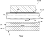
- This coil receptacle 52 extends longitudinally along a longitudinal centerline 54 of the coil receptacle 52 through the respective EM field concentrator 36 between and to a first end 55A of the respective EM field concentrator 36 and a second end 55B of the respective EM field concentrator 36, where the receptacle centerline 54 may be parallel with and/or coaxial with the coil centerline 44 along the welding segment 46; see also FIG. 5 .
- the coil receptacle 52 extends laterally within the respective EM field concentrator 36 between and to opposing sides 56A and 56B (generally referred to as "56") of the coil receptacle 52.
- the coil receptacle 52 projects vertically (e.g., partially) into the respective EM field concentrator 36 from a receptacle opening 58 in a face surface 60 of the respective EM field concentrator 36 to an end 62 of the coil receptacle 52.
- This face surface 60 may be configured to substantially match the exterior surface contour of the workpiece 22 of FIG. 1 to be induction welded.
- the face surface 60 for example, may be flat where the workpiece 22 has the flat exterior surface.
- the face surface 60 may alternatively have a non-flat (e.g., curved, compound, concave, convex, etc.) where the workpiece exterior surface 48 is a non-flat.
- the induction welding coil 42 is received in each coil receptacle 52.
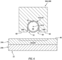
- the welding segment 46 of the induction welding coil 42 of FIGS. 5 and 6 for example, is seated within the coil receptacle 52.
- the induction welding coil 42 of FIG. 5 extends longitudinally along the centerline 44, 54 within (e.g., through) the coil receptacle 52.
- each EM field concentrator 36A, 36B of FIGS. 5 and 6 covers a select portion of the welding segment 46 at the receptacle sides 56 and the receptacle end 62.
- Each EM field concentrator 36 may thereby concentrate a select portion of an electromagnetic field generated by the induction welding coil 42 and its welding segment 46 towards / onto a respective region 64A, 64B (generally referred to as "64") of the workpiece 22 and at least its (e.g., top) vertically closest workpiece body 24A through the receptacle opening 58. More particularly, rather than emit the electromagnetic field 66 of FIG. 7A radially all about the induction welding coil 42 and its welding segment 46, each electromagnetic field 66' of FIG. 7B emitted from the induction welding coil 42 and its welding segment 46 may be focused towards / onto the region. Each EM field concentrator 36 may thereby effectively magnify a power of the electromagnetic field during the induction welding of the workpiece bodies 24 together.
- a temperature of a melt layer 68 formed at an interface between the first body 24A and the second body 24B may vary (e.g., significantly) along a longitudinal length of the melt layer 68.
- the melt layer temperature may be relatively high at an end 70A, 70B (generally referred to as "70") of the workpiece 22 and its workpiece bodies 24, but quickly dip down and then rise back up as the melt layer 68 extends longitudinally along the welding segment 46 / the centerline 44 to a center of the workpiece 22 and its workpiece bodies 24.
- the temperature along the melt layer 68 may be divided into several regions 72-74.
- the opposing end regions 72 of the melt layer 68 are located longitudinally at the workpiece ends 70.
- the intermediate region 73 of the melt layer 68 is located longitudinally centrally along the melt layer 68.
- Each transition region 74 of the melt layer 68 extends longitudinally between a respective one of the end regions 72 and the intermediate region 73, where a longitudinal length of the intermediate region 73 may be greater than a longitudinal length of each transition region 74, and where the longitudinal length of each transition region 74 may be greater than (or equal to) a longitudinal length of the each end region 72.
- Each transition region 74 is located proximate (e.g., close to) a respective one of the workpiece ends 70.
- melt layer temperature within the transition regions 74 may be lower than the melt layer temperature within one or more of the other regions 72 and/or 73. Such a variation in melt layer temperature may reduce or otherwise compromise a strength of a weld seam 76 between the workpiece bodies 24 under certain conditions.
- the EM field concentrators 36 of FIG. 8B are selectively located to raise the melt layer temperature of otherwise relatively cool regions of the melt layer 68; e.g., the transition regions 74. More particularly, by longitudinally aligning the EM field concentrators 36 with predicted low temperature regions of the melt layer 68, each EM field concentrator 36 may concentrate the electromagnetic field to raise the temperature of those low temperature regions of the melt layer 68. For example, each of the EM field concentrators 36 may be longitudinally aligned with and longitudinally overlap a respective one of the transition regions 74 at (or about) a respective one of the workpiece ends 70. With this arrangement, the temperature of the melt layer 68 may remain substantially constant (or within a relatively small range) longitudinally across the workpiece 22.
- Characteristics of the electromagnetic field concentrated by each EM field concentrator 36 may be tuned by adjusting placement of the induction welding coil 42 and its welding segment 46 within the respective EM field concentrator 36 and its coil receptacle 52.
- the induction welding coil 42 and its welding segment 46 may be arranged flush with the face surface 60.
- An exterior side 78 of the induction welding coil 42 and its welding segment 46 of FIG. 9A is vertically aligned with the face surface 60 at the receptacle opening 58.
- a vertical distance 80 through an open volume 82 (e.g., a cavity, an air gap, etc.) from the workpiece 22 and the face surface 60 may be equal to a vertical distance 84 through the open volume 82 from the workpiece 22 to the welding segment 46.
- the concentrated electromagnetic field may thereby have a relatively large focus area.
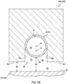
- the induction welding coil 42 and its welding segment 46 may be recessed vertically into the coil receptacle 52 from the face surface 60.
- the vertical distance 80 is less than the vertical distance 84 through the open volume 82, 86 from the workpiece 22 to the welding segment 46.
- the concentrated electromagnetic field may thereby have a relatively narrow focus area.
- the induction welding coil 42 and its welding segment 46 may be attached to each EM field concentrator 36.
- the welding segment 46 for example, may be secured to each EM field concentrator 36 via a mechanical interface; e.g., an interference fit.
- the welding segment 46 may also or alternatively be secured to one or more or each of the EM field concentrators 36 via thermally conductive bonding material; e.g., thermally conductive paste.
- the induction welding coil 42 and its welding segment 46 are thermally coupled to each EM field concentrator 36 through a thermally conductive interface; e.g., direct contact or through bonding material.
- the cooling device 32 FIG. 1 may direct its fluid (e.g., liquid coolant) through the internal bore 50 to cool the induction welding coil 42 as well as the thermally coupled EM field concentrators 36.
- Each of the EM field concentrators 36 may be configured as a monolithic body.
- Each EM field concentrator 36 may be cast, machined, additively manufactured and/or otherwise formed as a single unitary body.
- This body may be constructed from or otherwise include a metal material; e.g., an iron based metal.
- the present disclosure is not limited to such an exemplary concentrator construction or materials.
- FIG. 10 is a flow diagram of a method 1000 for manufacturing the workpiece 22.
- This workpiece 22 may be configured as a fan cowl for a nacelle of an aircraft propulsion system.
- the workpiece 22, however, may alternatively be configured as or may otherwise be included as part of another nacelle component, an aircraft control surface, a wing or an aircraft fuselage.
- the present disclosure is not limited to manufacturing such exemplary components or to aircraft propulsion system applications.
- the manufacturing method 1000 may be performed for manufacturing any type or configuration of component where two or more bodies are joined via induction welding.
- the manufacturing method 1000 is described below with reference to the induction welder 20 of FIGS. 1 , 8B and 11 .
- the manufacturing method 1000 of the present disclosure is not limited to any particular induction welder configurations.
- step 1002 the induction welder 20 is provided.
- the first body 24A and the second body 24B are provided.
- Each of these workpiece bodies 24 may be configured as a thermoplastic body.
- Each of the workpiece bodies 24 of FIG. 11 includes the fiber reinforcement 26 (e.g., carbon fibers) embedded within the thermoplastic matrix 28.
- the first body 24A is arranged with the second body 24B.
- the second body 24B is next to and vertically engages (e.g., contacts) the first body 24A.
- the first body 24A is separated from the induction welding coil 42 and its welding segment 46 as well as each EM field concentrator 36 by the open volume 82.
- Each face surface 60 faces and is vertically next to (e.g., but, slightly vertically spaced from) the first body 24A.
- the first body 24A is induction welded to the second body 24B.
- the power source 30 may provide a high frequency (e.g., alternating) current to the induction welding coil 42.
- the induction welding coil 42 may subsequently generate electromagnetic waves. These electromagnetic waves (some of which are unconcentrated and some of which are concentrated by the EM field concentrators 36) excite one or more reinforcement fibers of the fiber reinforcement 26 via eddy currents within the first body 24A and/or one or more reinforcement fibers of the fiber reinforcement 26 via eddy currents within the second body 24B.
- This excitation may elevate a temperature of the first body 24A and/or the second body 24B to a melting point temperature where the thermoplastic matrix 28 of the first body 24A and/or the thermoplastic matrix 28 of the second body 24B melts.
- the melt layer 68 may form at the interface between the first body 24A and the second body 24B. This melt layer 68 may bond the first body 24A and the second body 24B together upon cooling thereof where the melt layer 68 provides the elongated weld seam 76. Since the welding segment 46 extends across the entire workpiece 22, the induction welder 20 and its components 34 and 36 may remain stationary (e.g., do not move at all and/or do not move relative to the workpiece 22 and its workpiece bodies 24) during the induction welding step 1008.
- the cooling device 32 of FIG. 1 may flow coolant through the coil structure 34.
- the cooling device 32 of FIG. 1 may flow (e.g., circulate) the coolant sequentially through the first lead 40, the induction welding coil 42 and the second lead 41, or vice versa.
- Flowing of the coolant reduces the temperature of the coil structure 34 as well as the EM field concentrators 36 such that, for example, heat radiated from the induction welding coil 42 and/or the EM field concentrators 36 does not melt the thermoplastic matrix 28 of the adjacent workpiece 22 and its first body 24A.
- each EP field concentrator 36 has a longitudinal length 87A between its ends 55A and 55B.
- This concentrator length 87A is less than a longitudinal length 87B of the workpiece 22 and its workpiece bodies 24 between their ends 70A and 70B.
- the workpiece length 87B may be more than two times (2x), three times (3x), four times (4x) or more the concentrator length 87A; e.g., between 2x to 15x.
- the present disclosure is not limited to such an exemplary dimensional relationship.
- the workpiece length 87B may be less than two times (2x) greater than or more than fifteen times (15x) greater than the concentrator length 87A.
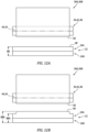
- the workpiece 22 and its workpiece bodies 24 may have a uniform vertical thickness 88.
- the workpiece thickness 88 of FIG. 12A may remain constant at least longitudinally along the welding segment 46.
- the workpiece 22 and at least one (or each) of its workpiece bodies 24 may have a variable vertical thickness.
- a thin portion of the workpiece 22, for example, may have a relatively small workpiece thickness 88A whereas a thick portion of the workpiece 22 may have a relatively large workpiece thickness 88B.
- a respective EM field concentrator 36 may be longitudinally aligned with (e.g., overlap) the thick portion, and may be longitudinally misaligned from (not overlap) the adjacent thin portion(s).
- At least a portion or an entirety of the induction welding coil 42 and its welding segment 46 may have a circular cross-sectional geometry when viewed, for example, in a reference plane perpendicular to the centerline 44, 54.
- the present disclosure is not limited to such an exemplary configuration.
- at least a portion or the entirety of the induction welding coil 42 and its welding segment 46 may alternatively have a polygonal cross-sectional geometry when viewed, for example, in the reference plane.
- the polygonal cross-sectional geometry of FIG. 13 is square.
- the polygonal cross-sectional geometry of FIG. 14 is triangular.
- Such polygonal cross-sectional geometries may facilitate decreasing an average distance from the induction welding coil 42 and its welding segment 46 to the bodies being welded where, for example, a flat surface of the coil 42 is parallel with the bodies.
- one or more or all of the EM field concentrators 36 may also or alternatively be directly cooled by the cooling device 32, or another cooling device.
- the cooling device 32 of FIG. 15 is configured to flow the fluid (e.g., liquid coolant) through one or more internal passages in the EM field concentrator 36.
- the cooling device 32 of FIG. 16 is configured to flow the fluid through one or more peripheral channels adjacent and/or partially formed by the EM field concentrator 36.
Landscapes
- Engineering & Computer Science (AREA)
- Mechanical Engineering (AREA)
- Physics & Mathematics (AREA)
- Thermal Sciences (AREA)
- Lining Or Joining Of Plastics Or The Like (AREA)
Abstract
Description
- This disclosure (invention) relates generally to joining bodies together and, more particularly, to induction welding.
- It is known in the art to join discrete bodies together using induction welding. These joined bodies are typically constructed from like materials; e.g., fiber-reinforced composite. The discrete bodies are induction welded together using an induction welder. Various types and configurations of induction welders are known in the art. While these known induction welders have various benefits, there is still room in the art for improvement. For example, there is a need in the art for an induction welder and method that can provide an enhanced and/or tuned electromagnetic field.
- According to an aspect of the present invention, a manufacturing method is provided. During this manufacturing method, an induction welder is provided that includes a concentrator and a coil extending through a receptacle in the concentrator. The receptacle projects into the concentrator from a face surface of the concentrator. A first thermoplastic body arranged with a second thermoplastic body are provided. The first thermoplastic body is located next to the face surface. The first thermoplastic body is induction welded to the second thermoplastic body to provide a weld seam between the first thermoplastic body and the second thermoplastic body. The concentrator extends along a portion of the weld seam. The induction welding includes: generating an electromagnetic field with the coil; and concentrating a portion of the electromagnetic field with the concentrator onto a region of the first thermoplastic body.
- According to another aspect of the present invention, another manufacturing method is provided. During this manufacturing method, an induction welder is provided that includes a first concentrator, a second concentrator and a coil extending within a first receptacle in the first concentrator and within a second receptacle in the second concentrator. The first receptacle projects into the first concentrator from a first face surface of the first concentrator. The second receptacle projects into the second concentrator from a second face surface of the second concentrator. A first thermoplastic body arranged with a second thermoplastic body are provided. The first thermoplastic body is located next to the first face surface and the second face surface. The first thermoplastic body is induction welded to the second thermoplastic body to provide a weld seam between the first thermoplastic body and the second thermoplastic body. the first concentrator is spaced from the second concentrator along the weld seam. The induction welding includes: generating an electromagnetic field with the coil; and concentrating the electromagnetic field with the first concentrator and the second concentrator onto respective regions of the first thermoplastic body.
- According to still another aspect of the present invention, another manufacturing method is provided. During this manufacturing method, an induction welder is provided that includes a concentrator and a coil extending through a receptacle in the concentrator. The receptacle projects into the concentrator from a face surface of the concentrator. A first thermoplastic body arranged with a second thermoplastic body are provided. The first thermoplastic body is located next to the face surface. The first thermoplastic body is induction welded to the second thermoplastic body to provide a weld seam between the first thermoplastic body and the second thermoplastic body while the induction welder is maintained stationary over the first thermoplastic body. The induction welding includes: generating an electromagnetic field with the coil; and concentrating at least a portion the electromagnetic field with the concentrator onto a region of the first thermoplastic body.
- The following optional features may be applied to any of the above aspects of the invention.
- The concentrator may be arranged at a first end of the first thermoplastic body. The concentrator may be spaced from a second end of the thermoplastic body that is opposite the first end.
- The induction welder may be maintained stationary during the induction welding.
- The concentrator may have a concentrator length along a centerline. The weld seam may have a seam length along the centerline that is greater than the concentrator length.
- The seam length may be at least two times greater than the concentrator length.
- The receptacle may project vertically into the concentrator from the face surface to an end of the receptacle. The receptacle may extend laterally within the concentrator between opposing sides of the receptacle. The receptacle may extend longitudinally within the concentrator along a centerline. The coil may be seated and may extend longitudinally along the centerline within the receptacle.
- An open space may extend vertically between the first thermoplastic body and the coil.
- An open space may extend vertically between the first thermoplastic body and the concentrator.
- The coil may be vertically flush with the face surface.
- The coil may be recessed vertically into the receptacle from the face surface.
- The coil may be thermally coupled to the concentrator through a conductive interface.
- The manufacturing method may also include cooling the coil and/or the concentrator using liquid coolant.
- The cooling may include directing the liquid coolant through a bore of the coil.
- The induction welder may also include a second concentrator. The coil may extend through a second receptacle in the second concentrator. The second receptacle may project into the second concentrator from a second face surface of the second concentrator. The second concentrator may extend along a second portion of the weld seam. The induction welding may also include concentrating a second portion of the electromagnetic field with the second concentrator onto a second region of the first thermoplastic body.
- The concentrator may be spaced from the second concentrator along the weld seam.
- A first end portion of the weld seam proximate a first end of the first thermoplastic body may be longitudinally overlapped by the concentrator. A second end portion of the weld seam proximate a second end of the first thermoplastic body may be longitudinally overlapped by the second concentrator. An intermediate portion of the weld seam longitudinally between the first end portion and the second end portion may be longitudinally misaligned from the concentrator and the second concentrator.
- A workpiece may include the first thermoplastic body and the second thermoplastic body. A thickness of the workpiece along the weld seam may be uniform.
- A workpiece may include the first thermoplastic body and the second thermoplastic body. A thickness of the workpiece along the weld seam may vary.
- A workpiece may include the first thermoplastic body and the second thermoplastic body. The workpiece along a first portion of the weld seam may have a first thickness. The first portion of the weld seam may be overlapped by the concentrator. The workpiece along a second portion of the weld seam may have a second thickness that is different than the first thickness. The second portion of the weld seam may be misaligned from the concentrator.
- The present disclosure may include any one or more of the individual features disclosed above and/or below alone or in any combination thereof.
- The coil may have a circular cross-sectional geometry.
- The coil may have a polygonal cross-sectional geometry.
- The foregoing features and the operation of the invention will become more apparent in light of the following description and the accompanying drawings.
-
-
FIG. 1 is a schematic illustration of an induction welder for induction welding a workpiece. -
FIG. 2 is a schematic illustration of a coil structure configured with a power source and a cooling device. -
FIG. 3 is a side sectional illustration of an electromagnetic field concentrator. -
FIG. 4 is a cross-sectional illustration of the electromagnetic field concentrator. -
FIG. 5 is a side sectional illustration of a portion of the induction welder next to the workpiece. -
FIG. 6 is a cross-sectional illustration of a portion of the induction welder next to the workpiece. -
FIG. 7A is an illustration depicting an unfocused electromagnetic field generated by an induction welding coil. -
FIG. 7B is an illustration depicting an electromagnetic field generated by the induction welding coil and concentrated by the electromagnetic field concentrator. -
FIG. 8A is an illustration depicting melt layer temperature along the induction welder coil without electromagnetic field concentration. -
FIG. 8B is an illustration depicting the melt layer temperature along the induction welder coil with select electromagnetic field concentration. -
FIGS. 9A and9B are cross-sectional illustrations of a portion of the induction welder with various different electromagnetic field concentrator configurations next to the workpiece. -
FIG. 10 is a flow diagram of a method for manufacturing the workpiece. -
FIG. 11 is a cross-sectional illustration of a portion of the induction welder next to the workpiece during induction welding of the workpiece. -
FIGS. 12A and 12B are schematic illustrations of a portion of the induction welder next to various different workpieces. -
FIG. 13 is a cross-sectional illustration of the induction welding coil configured with a square geometry. -
FIG. 14 is a cross-sectional illustration of the induction welding coil configured with a triangular geometry. -
FIGS. 15 and 16 are schematic illustrations of various arrangements for directly cooling the electromagnetic field concentrator. -
FIG. 1 illustrates aninduction welder 20 for induction welding aworkpiece 22. Thisworkpiece 22 may include two ormore bodies induction welder 20 may induction weld these workpiece bodies 24 together. Each of the workpiece bodies 24 is formed from an induction weldable material such as, but not limited to, a fiber-reinforced thermoplastic. Each of the workpiece bodies 24, for example, may be constructed from or otherwise include fiber reinforcement 26 (e.g., carbon fibers) embedded within athermoplastic matrix 28. Theinduction welder 20 ofFIG. 1 includes apower source 30, acooling device 32 and acoil structure 34. Theinduction welder 20 ofFIG. 1 also includes one or more electromagnetic (EM)field concentrators coil structure 34. - The
power source 30 is configured to generate a periodic electrical current. Thepower source 30, for example, may be configured as a high-frequency current source. Thepower source 30 may be or otherwise include an alternating current (AC) generator, transformer, amplifier, etc. Alternatively, thepower source 30 may include a direct current (DC) generator, transformer, amplifier, battery, etc. electrically coupled with an oscillator. The present disclosure, however, is not limited to such exemplary power sources. - The
cooling device 32 is configured to flow fluid (e.g., liquid coolant) through thecoil structure 34. Thecooling device 32, for example, may be configured as a liquid pump coupled with a coolant reservoir and a heat exchanger. The present disclosure, however, is not limited to such an exemplary cooling device. - Referring to
FIG. 2 , thecoil structure 34 may be formed from or otherwise include a single length (or multiple end-to-end interconnected lengths) of electricallyconductive tubing 38. Thistubing 38 is constructed from electrically conductive material such as metal; e.g., copper (Cu). Thecoil structure 34 ofFIG. 2 includes an (e.g., tubular) electricalfirst lead 40, an (e.g., tubular) electricalsecond lead 41 and an (e.g., tubular)induction welding coil 42. - The
first lead 40 may be a first section of thecoil structure 34 and its electricallyconductive tubing 38. Thesecond lead 41 may be a second section of thecoil structure 34 and its electricallyconductive tubing 38. Thefirst lead 40 may be arranged parallel with thesecond lead 41. Thefirst lead 40 and thesecond lead 41 are connected to opposing ends of theinduction welding coil 42. Thefirst lead 40 and thesecond lead 41 electrically couple theinduction welding coil 42 to respective terminals of thepower source 30. - The
induction welding coil 42 may be an intermediate section of thecoil structure 34 and its electricallyconductive tubing 38 longitudinally between thefirst lead 40 and thesecond lead 41. Theinduction welding coil 42 may be configured as an elongated loop. Theinduction welding coil 42 ofFIG. 2 , for example, extends along a non-straight (e.g., generally racetrack shaped) portion of alongitudinal centerline 44 of thecoil structure 34 between and to the coil ends. Theinduction welding coil 42 ofFIG. 2 includes at least (or only) one welding (e.g., bottom side)segment 46. Theinduction welding coil 42, for example, may be configured as a single hairpin coil. Thewelding segment 46 may be configured to substantially match a contour of anexterior surface 48 of theworkpiece 22 ofFIG. 1 to be induction welded. Thewelding segment 46, for example, may be straight where theworkpiece 22 has a flat exterior surface. Thewelding segment 46 may alternatively be non-straight (e.g., curved, compound, etc.) where theworkpiece exterior surface 48 is a non-straight; e.g., curved, compound, etc. The present disclosure, however, is not limited to the foregoing exemplary induction welding coil configurations. - The
coil structure 34 ofFIG. 2 is configured with aninternal bore 50. This internal bore 50 extends longitudinally along thecoil centerline 44 through thecoil structure 34 and its components 40-42 between and to opposing distal ends of thecoil structure 34 and itsleads internal bore 50 is fluidly coupled with thecooling device 32 through couplings at the structure ends. Thefirst lead 40 and thesecond lead 41 thereby fluidly couple theinduction welding coil 42 to thecooling device 32. - Referring to
FIG. 3 , each of theEM field concentrators 36 is configured with an inductionwelding coil receptacle 52; e.g., a channel. Thiscoil receptacle 52 extends longitudinally along alongitudinal centerline 54 of thecoil receptacle 52 through the respectiveEM field concentrator 36 between and to afirst end 55A of the respectiveEM field concentrator 36 and asecond end 55B of the respectiveEM field concentrator 36, where thereceptacle centerline 54 may be parallel with and/or coaxial with thecoil centerline 44 along thewelding segment 46; see alsoFIG. 5 . Referring toFIG. 4 , thecoil receptacle 52 extends laterally within the respectiveEM field concentrator 36 between and to opposingsides coil receptacle 52. Thecoil receptacle 52 projects vertically (e.g., partially) into the respectiveEM field concentrator 36 from areceptacle opening 58 in aface surface 60 of the respectiveEM field concentrator 36 to anend 62 of thecoil receptacle 52. Thisface surface 60 may be configured to substantially match the exterior surface contour of theworkpiece 22 ofFIG. 1 to be induction welded. Theface surface 60, for example, may be flat where theworkpiece 22 has the flat exterior surface. Theface surface 60 may alternatively have a non-flat (e.g., curved, compound, concave, convex, etc.) where theworkpiece exterior surface 48 is a non-flat. - Referring to
FIGS. 5 and6 , theinduction welding coil 42 is received in eachcoil receptacle 52. Thewelding segment 46 of theinduction welding coil 42 ofFIGS. 5 and6 , for example, is seated within thecoil receptacle 52. Theinduction welding coil 42 ofFIG. 5 extends longitudinally along thecenterline coil receptacle 52. With this arrangement, eachEM field concentrator FIGS. 5 and6 covers a select portion of thewelding segment 46 at the receptacle sides 56 and thereceptacle end 62. EachEM field concentrator 36 may thereby concentrate a select portion of an electromagnetic field generated by theinduction welding coil 42 and itswelding segment 46 towards / onto arespective region workpiece 22 and at least its (e.g., top) verticallyclosest workpiece body 24A through thereceptacle opening 58. More particularly, rather than emit theelectromagnetic field 66 ofFIG. 7A radially all about theinduction welding coil 42 and itswelding segment 46, eachelectromagnetic field 66' ofFIG. 7B emitted from theinduction welding coil 42 and itswelding segment 46 may be focused towards / onto the region. EachEM field concentrator 36 may thereby effectively magnify a power of the electromagnetic field during the induction welding of the workpiece bodies 24 together. - Referring to
FIG. 8A , during induction welding of theworkpiece 22 without theEM field concentrators 36, a temperature of a melt layer 68 formed at an interface between thefirst body 24A and thesecond body 24B may vary (e.g., significantly) along a longitudinal length of the melt layer 68. The melt layer temperature, for example, may be relatively high at anend workpiece 22 and its workpiece bodies 24, but quickly dip down and then rise back up as the melt layer 68 extends longitudinally along thewelding segment 46 / thecenterline 44 to a center of theworkpiece 22 and its workpiece bodies 24. The temperature along the melt layer 68, for example, may be divided into several regions 72-74. The opposingend regions 72 of the melt layer 68 are located longitudinally at the workpiece ends 70. Theintermediate region 73 of the melt layer 68 is located longitudinally centrally along the melt layer 68. Eachtransition region 74 of the melt layer 68 extends longitudinally between a respective one of theend regions 72 and theintermediate region 73, where a longitudinal length of theintermediate region 73 may be greater than a longitudinal length of eachtransition region 74, and where the longitudinal length of eachtransition region 74 may be greater than (or equal to) a longitudinal length of the eachend region 72. Eachtransition region 74, however, is located proximate (e.g., close to) a respective one of the workpiece ends 70. Due to thermodynamic end effects, the melt layer temperature within thetransition regions 74 may be lower than the melt layer temperature within one or more of theother regions 72 and/or 73. Such a variation in melt layer temperature may reduce or otherwise compromise a strength of a weld seam 76 between the workpiece bodies 24 under certain conditions. - To account for the longitudinal melt layer temperature gradient along the
welding segment 46, theEM field concentrators 36 ofFIG. 8B are selectively located to raise the melt layer temperature of otherwise relatively cool regions of the melt layer 68; e.g., thetransition regions 74. More particularly, by longitudinally aligning theEM field concentrators 36 with predicted low temperature regions of the melt layer 68, eachEM field concentrator 36 may concentrate the electromagnetic field to raise the temperature of those low temperature regions of the melt layer 68. For example, each of theEM field concentrators 36 may be longitudinally aligned with and longitudinally overlap a respective one of thetransition regions 74 at (or about) a respective one of the workpiece ends 70. With this arrangement, the temperature of the melt layer 68 may remain substantially constant (or within a relatively small range) longitudinally across theworkpiece 22. - Characteristics of the electromagnetic field concentrated by each
EM field concentrator 36 may be tuned by adjusting placement of theinduction welding coil 42 and itswelding segment 46 within the respectiveEM field concentrator 36 and itscoil receptacle 52. For example, referring toFIG. 9A , theinduction welding coil 42 and itswelding segment 46 may be arranged flush with theface surface 60. Anexterior side 78 of theinduction welding coil 42 and itswelding segment 46 ofFIG. 9A , for example, is vertically aligned with theface surface 60 at thereceptacle opening 58. With such an arrangement, avertical distance 80 through an open volume 82 (e.g., a cavity, an air gap, etc.) from theworkpiece 22 and theface surface 60 may be equal to avertical distance 84 through theopen volume 82 from theworkpiece 22 to thewelding segment 46. The concentrated electromagnetic field may thereby have a relatively large focus area. In another example, referring toFIG. 9B , theinduction welding coil 42 and itswelding segment 46 may be recessed vertically into thecoil receptacle 52 from theface surface 60. Thewelding segment 46 ofFIG. 9B , for example, is spaced vertically inward into thecoil receptacle 52 from thereceptacle opening 58 by an open receptacle volume 86 (e.g., a cavity, an air gap, etc.) such that the receptacle sides 56 project vertically beyond thecoil exterior side 78. With such an arrangement, thevertical distance 80 is less than thevertical distance 84 through theopen volume workpiece 22 to thewelding segment 46. The concentrated electromagnetic field may thereby have a relatively narrow focus area. - The
induction welding coil 42 and itswelding segment 46 may be attached to eachEM field concentrator 36. Thewelding segment 46, for example, may be secured to eachEM field concentrator 36 via a mechanical interface; e.g., an interference fit. Thewelding segment 46 may also or alternatively be secured to one or more or each of theEM field concentrators 36 via thermally conductive bonding material; e.g., thermally conductive paste. With such arrangements, theinduction welding coil 42 and itswelding segment 46 are thermally coupled to eachEM field concentrator 36 through a thermally conductive interface; e.g., direct contact or through bonding material. With such an arrangement, thecooling device 32FIG. 1 may direct its fluid (e.g., liquid coolant) through the internal bore 50 to cool theinduction welding coil 42 as well as the thermally coupledEM field concentrators 36. - Each of the
EM field concentrators 36 may be configured as a monolithic body. EachEM field concentrator 36, for example, may be cast, machined, additively manufactured and/or otherwise formed as a single unitary body. This body may be constructed from or otherwise include a metal material; e.g., an iron based metal. The present disclosure, however, is not limited to such an exemplary concentrator construction or materials. -
FIG. 10 is a flow diagram of amethod 1000 for manufacturing theworkpiece 22. Thisworkpiece 22 may be configured as a fan cowl for a nacelle of an aircraft propulsion system. Theworkpiece 22, however, may alternatively be configured as or may otherwise be included as part of another nacelle component, an aircraft control surface, a wing or an aircraft fuselage. The present disclosure, however, is not limited to manufacturing such exemplary components or to aircraft propulsion system applications. For example, themanufacturing method 1000 may be performed for manufacturing any type or configuration of component where two or more bodies are joined via induction welding. For ease of description, themanufacturing method 1000 is described below with reference to theinduction welder 20 ofFIGS. 1 ,8B and11 . Themanufacturing method 1000 of the present disclosure, however, is not limited to any particular induction welder configurations. - In
step 1002, theinduction welder 20 is provided. - In
step 1004, thefirst body 24A and thesecond body 24B are provided. Each of these workpiece bodies 24 may be configured as a thermoplastic body. Each of the workpiece bodies 24 ofFIG. 11 , for example, includes the fiber reinforcement 26 (e.g., carbon fibers) embedded within thethermoplastic matrix 28. - In
step 1006, thefirst body 24A is arranged with thesecond body 24B. In the arrangement ofFIG. 11 , thesecond body 24B is next to and vertically engages (e.g., contacts) thefirst body 24A. Thefirst body 24A is separated from theinduction welding coil 42 and itswelding segment 46 as well as eachEM field concentrator 36 by theopen volume 82. Eachface surface 60 faces and is vertically next to (e.g., but, slightly vertically spaced from) thefirst body 24A. - In
step 1008, thefirst body 24A is induction welded to thesecond body 24B. The power source 30 (seeFIG. 1 ), for example, may provide a high frequency (e.g., alternating) current to theinduction welding coil 42. Theinduction welding coil 42 may subsequently generate electromagnetic waves. These electromagnetic waves (some of which are unconcentrated and some of which are concentrated by the EM field concentrators 36) excite one or more reinforcement fibers of thefiber reinforcement 26 via eddy currents within thefirst body 24A and/or one or more reinforcement fibers of thefiber reinforcement 26 via eddy currents within thesecond body 24B. This excitation may elevate a temperature of thefirst body 24A and/or thesecond body 24B to a melting point temperature where thethermoplastic matrix 28 of thefirst body 24A and/or thethermoplastic matrix 28 of thesecond body 24B melts. The melt layer 68 may form at the interface between thefirst body 24A and thesecond body 24B. This melt layer 68 may bond thefirst body 24A and thesecond body 24B together upon cooling thereof where the melt layer 68 provides the elongated weld seam 76. Since thewelding segment 46 extends across theentire workpiece 22, theinduction welder 20 and itscomponents workpiece 22 and its workpiece bodies 24) during theinduction welding step 1008. - Before, during and/or after the induction welding of the first and the second bodies, the
cooling device 32 ofFIG. 1 may flow coolant through thecoil structure 34. Thecooling device 32 ofFIG. 1 , for example, may flow (e.g., circulate) the coolant sequentially through thefirst lead 40, theinduction welding coil 42 and thesecond lead 41, or vice versa. Flowing of the coolant reduces the temperature of thecoil structure 34 as well as theEM field concentrators 36 such that, for example, heat radiated from theinduction welding coil 42 and/or theEM field concentrators 36 does not melt thethermoplastic matrix 28 of theadjacent workpiece 22 and itsfirst body 24A. - Referring to
FIG. 1 , eachEP field concentrator 36 has alongitudinal length 87A between itsends concentrator length 87A is less than alongitudinal length 87B of theworkpiece 22 and its workpiece bodies 24 between theirends workpiece length 87B, for example, may be more than two times (2x), three times (3x), four times (4x) or more theconcentrator length 87A; e.g., between 2x to 15x. The present disclosure, however, is not limited to such an exemplary dimensional relationship. For example, in other embodiments, theworkpiece length 87B may be less than two times (2x) greater than or more than fifteen times (15x) greater than theconcentrator length 87A. - In some embodiments, referring to
FIG. 12A , theworkpiece 22 and its workpiece bodies 24 may have a uniformvertical thickness 88. Theworkpiece thickness 88 ofFIG. 12A , for example, may remain constant at least longitudinally along thewelding segment 46. In other embodiments, referring toFIG. 12B , theworkpiece 22 and at least one (or each) of its workpiece bodies 24 may have a variable vertical thickness. A thin portion of theworkpiece 22, for example, may have a relativelysmall workpiece thickness 88A whereas a thick portion of theworkpiece 22 may have a relativelylarge workpiece thickness 88B. A respectiveEM field concentrator 36 may be longitudinally aligned with (e.g., overlap) the thick portion, and may be longitudinally misaligned from (not overlap) the adjacent thin portion(s). - In some embodiments, referring to
FIG. 11 , at least a portion or an entirety of theinduction welding coil 42 and itswelding segment 46 may have a circular cross-sectional geometry when viewed, for example, in a reference plane perpendicular to thecenterline FIGS. 13 and 14 , at least a portion or the entirety of theinduction welding coil 42 and itswelding segment 46 may alternatively have a polygonal cross-sectional geometry when viewed, for example, in the reference plane. The polygonal cross-sectional geometry ofFIG. 13 is square. The polygonal cross-sectional geometry ofFIG. 14 is triangular. Such polygonal cross-sectional geometries may facilitate decreasing an average distance from theinduction welding coil 42 and itswelding segment 46 to the bodies being welded where, for example, a flat surface of thecoil 42 is parallel with the bodies. - In some embodiments, referring to
FIGS. 15 and 16 , one or more or all of theEM field concentrators 36 may also or alternatively be directly cooled by the coolingdevice 32, or another cooling device. Thecooling device 32 ofFIG. 15 , for example, is configured to flow the fluid (e.g., liquid coolant) through one or more internal passages in theEM field concentrator 36. Thecooling device 32 ofFIG. 16 is configured to flow the fluid through one or more peripheral channels adjacent and/or partially formed by theEM field concentrator 36. - While various embodiments of the present invention have been disclosed, it will be apparent to those of ordinary skill in the art that many more embodiments and implementations are possible within the scope of the invention. For example, the present invention as described herein includes several aspects and embodiments that include particular features. Although these features may be described individually, it is within the scope of the present invention that some or all of these features may be combined with any one of the aspects and remain within the scope of the invention. Accordingly, the present invention is not to be restricted except in light of the attached claims and their equivalents.
Claims (15)
- A manufacturing method, comprising:providing an induction welder (20) including a concentrator and a coil (42) extending through a receptacle in the concentrator, the receptacle projecting into the concentrator from a face surface (60) of the concentrator;providing a first thermoplastic body arranged with a second thermoplastic body, the first thermoplastic body located next to the face surface (60); andinduction welding the first thermoplastic body to the second thermoplastic body to provide a weld seam (76) between the first thermoplastic body and the second thermoplastic body, the concentrator extending along a portion of the weld seam (76), the induction welding comprisinggenerating an electromagnetic field (66; 66') with the coil (42); andconcentrating a portion of the electromagnetic field (66; 66') with the concentrator onto a region (64A) of the first thermoplastic body.
- The manufacturing method of claim 1, wherein the induction welder (20) is maintained stationary during the induction welding.
- The manufacturing method of claim 1 or 2, wherein:the concentrator has a concentrator length (87A) along a centerline (44); andthe weld seam (76) has a seam length along the centerline (44) that is greater than the concentrator length (87A), wherein the seam length is optionally at least two times greater than the concentrator length (87A).
- The manufacturing method of claim 1, 2 or 3, wherein:the receptacle projects vertically into the concentrator from the face surface (60) to an end (62; 70A) of the receptacle;the receptacle extends laterally within the concentrator between opposing sides (56A) of the receptacle;the receptacle extends longitudinally within the concentrator along a centerline (44); andthe coil (42) is seated and extends longitudinally along the centerline (44) within the receptacle.
- The manufacturing method of any preceding claim, wherein an open space extends vertically between the first thermoplastic body and the coil (42), or the first thermoplastic body and the concentrator.
- The manufacturing method of any preceding claim, wherein the coil (42) is vertically flush with the face surface (60), or the coil (42) is recessed vertically into the receptacle from the face surface (60).
- The manufacturing method of any preceding claim, wherein the coil (42) is thermally coupled to the concentrator through a conductive interface.
- The manufacturing method of any preceding claim, further comprising cooling at least one of the coil (42) or the concentrator using liquid coolant, wherein the cooling optionally comprises directing the liquid coolant through a bore of the coil (42).
- The manufacturing method of any preceding claim, whereinthe induction welder (20) further includes a second concentrator, the coil (42) extends through a second receptacle in the second concentrator, and the second receptacle projects into the second concentrator from a second face surface (60) of the second concentrator;the second concentrator extends along a second portion of the weld seam (76); andthe induction welding further comprises concentrating a second portion of the electromagnetic field (66; 66') with the second concentrator onto a second region (64A) of the first thermoplastic body, wherein the concentrator is optionally spaced from the second concentrator along the weld seam (76).
- The manufacturing method of claim 9, whereina first end (55A) portion of the weld seam (76) proximate a first end (55A) of the first thermoplastic body is longitudinally overlapped by the concentrator;a second end (55B) portion of the weld seam (76) proximate a second end (55B) of the first thermoplastic body is longitudinally overlapped by the second concentrator; andan intermediate portion of the weld seam (76) longitudinally between the first end (55A) portion and the second end (55B) portion is longitudinally misaligned from the concentrator and the second concentrator.
- The manufacturing method of any preceding claim, whereina workpiece (22) includes the first thermoplastic body and the second thermoplastic body;a thickness of the workpiece (22) along the weld seam (76) is uniform.
- The manufacturing method of any of claims 1-10, whereina workpiece (22) includes the first thermoplastic body and the second thermoplastic body;the workpiece (22) along a first portion of the weld seam (76) has a first thickness, and the first portion of the weld seam (76) is overlapped by the concentrator; andthe workpiece (22) along a second portion of the weld seam (76) has a second thickness that is different than the first thickness, and the second portion of the weld seam (76) is misaligned from the concentrator.
- The manufacturing method of any preceding claim, wherein the coil (42) has a polygonal cross-sectional geometry.
- A manufacturing method, comprising:providing an induction welder (20) including a first concentrator, a second concentrator and a coil (42) extending within a first receptacle in the first concentrator and within a second receptacle in the second concentrator, the first receptacle projecting into the first concentrator from a first face surface (60) of the first concentrator, and the second receptacle projecting into the second concentrator from a second face surface (60) of the second concentrator;providing a first thermoplastic body arranged with a second thermoplastic body, the first thermoplastic body located next to the first face surface (60) and the second face surface (60); andinduction welding the first thermoplastic body to the second thermoplastic body to provide a weld seam (76) between the first thermoplastic body and the second thermoplastic body, the first concentrator spaced from the second concentrator along the weld seam (76), the induction welding comprisinggenerating an electromagnetic field (66; 66') with the coil (42); andconcentrating the electromagnetic field (66; 66') with the first concentrator and the second concentrator onto respective regions (72) of the first thermoplastic body.
- A manufacturing method, comprising:providing an induction welder (20) including a concentrator and a coil (42) extending through a receptacle in the concentrator, the receptacle projecting into the concentrator from a face surface (60) of the concentrator;providing a first thermoplastic body arranged with a second thermoplastic body, the first thermoplastic body located next to the face surface (60); andinduction welding the first thermoplastic body to the second thermoplastic body to provide a weld seam (76) between the first thermoplastic body and the second thermoplastic body while the induction welder (20) is maintained stationary over the first thermoplastic body, the induction welding comprisinggenerating an electromagnetic field (66; 66') with the coil (42); andconcentrating at least a portion the electromagnetic field (66; 66') with the concentrator onto a region (64A) of the first thermoplastic body.
Applications Claiming Priority (1)
| Application Number | Priority Date | Filing Date | Title |
|---|---|---|---|
| US17/566,219 US11865791B2 (en) | 2021-12-30 | 2021-12-30 | Induction welding with an electromagnetic field concentrator |
Publications (1)
| Publication Number | Publication Date |
|---|---|
| EP4205956A1 true EP4205956A1 (en) | 2023-07-05 |
Family
ID=84689283
Family Applications (1)
| Application Number | Title | Priority Date | Filing Date |
|---|---|---|---|
| EP22217220.7A Pending EP4205956A1 (en) | 2021-12-30 | 2022-12-29 | Induction welding with an electromagnetic field concentrator |
Country Status (2)
| Country | Link |
|---|---|
| US (1) | US11865791B2 (en) |
| EP (1) | EP4205956A1 (en) |
Families Citing this family (2)
| Publication number | Priority date | Publication date | Assignee | Title |
|---|---|---|---|---|
| EP4491380A1 (en) * | 2023-07-13 | 2025-01-15 | Facc Ag | Method for producing a fiber-plastic composite (fkv) component, induction welding method, and fkv composite part |
| CN119748880B (en) * | 2025-01-08 | 2025-10-17 | 西北工业大学 | A method for induction welding of thermoplastic composite materials based on magnetic concentrator |
Citations (2)
| Publication number | Priority date | Publication date | Assignee | Title |
|---|---|---|---|---|
| US5013878A (en) * | 1988-12-20 | 1991-05-07 | International Paper Company | Induction heat sealing lap-seamed containers to non-metallic closures |
| EP1413520A1 (en) * | 2002-10-24 | 2004-04-28 | Tetra Laval Holdings & Finance S.A. | Sealing jaw |
Family Cites Families (21)
| Publication number | Priority date | Publication date | Assignee | Title |
|---|---|---|---|---|
| US2483973A (en) | 1945-09-07 | 1949-10-04 | Chain Belt Co | Apparatus for welding the seams of tubular articles |
| US2846554A (en) | 1954-11-30 | 1958-08-05 | Metallurg Tech Et Commerciale | Butt welding of metal tubes |
| GB849672A (en) | 1957-02-20 | 1960-09-28 | K Schweisswerk Halle Veb | Apparatus for and method of building up the surface of metallic bodies, such as metal rolls by welding |
| JPH04504386A (en) | 1989-01-10 | 1992-08-06 | コートールズ パブリック リミティド カンパニー | How to join composite materials |
| US5047605A (en) | 1989-05-10 | 1991-09-10 | Abbott Laboratories | Induction welding apparatus and method |
| US4978825A (en) * | 1989-11-08 | 1990-12-18 | Northrop Corporation | Thermoplastic composite induction welder |
| US5444220A (en) | 1991-10-18 | 1995-08-22 | The Boeing Company | Asymmetric induction work coil for thermoplastic welding |
| SE503509C2 (en) * | 1992-02-07 | 1996-07-01 | Heat Tech Induction Ab | Process for welding together plastic sheets |
| US5438181A (en) | 1993-12-14 | 1995-08-01 | Essex Specialty Products, Inc. | Apparatus for heating substrate having electrically-conductive and non-electrically-conductive portions |
| US5635094A (en) | 1995-01-03 | 1997-06-03 | The Boeing Company | Conformal skate for induction welding |
| US7459053B2 (en) | 2005-05-11 | 2008-12-02 | Bone Jr Marvin J | Flux guide induction heating device and method of inductively heating elongated and nonuniform workpieces |
| CN203936495U (en) | 2014-01-27 | 2014-11-12 | 中国兵器科学研究院宁波分院 | A kind of welding induction coil |
| KR20170017900A (en) * | 2014-06-12 | 2017-02-15 | 테트라 라발 홀딩스 앤드 피낭스 소시에떼아노님 | An induction heating device |
| DE102014119700B3 (en) * | 2014-12-30 | 2015-11-19 | Sig Technology Ag | Apparatus and method for inductive heating of packing coats |
| US12161790B2 (en) | 2017-06-14 | 2024-12-10 | The University Of Vermont And State Agricultural College | Peritoneal dialysis (PD) catheter weighted anchor |
| EP4458685A3 (en) | 2018-05-03 | 2025-01-01 | Qarbon Aerospace (Foundation), LLC | Thermoplastic aerostructure with localized ply isolation and method for forming aerostructure |
| EP3661324B1 (en) | 2018-11-27 | 2022-10-05 | The Boeing Company | Heating circuit layout for smart susceptor induction heating apparatus |
| US11235537B2 (en) | 2019-07-01 | 2022-02-01 | The Boeing Company | Hybrid braided composite parts |
| US11286536B2 (en) | 2019-08-06 | 2022-03-29 | General Electric Company | System and method for manufacturing a part |
| US11524467B2 (en) | 2019-08-06 | 2022-12-13 | The Boeing Company | Induction welding using a heat sink and/or cooling |
| US11358344B2 (en) | 2019-08-06 | 2022-06-14 | The Boeiog Company | Induction welding using a heat sink and/or cooling |
-
2021
- 2021-12-30 US US17/566,219 patent/US11865791B2/en active Active
-
2022
- 2022-12-29 EP EP22217220.7A patent/EP4205956A1/en active Pending
Patent Citations (2)
| Publication number | Priority date | Publication date | Assignee | Title |
|---|---|---|---|---|
| US5013878A (en) * | 1988-12-20 | 1991-05-07 | International Paper Company | Induction heat sealing lap-seamed containers to non-metallic closures |
| EP1413520A1 (en) * | 2002-10-24 | 2004-04-28 | Tetra Laval Holdings & Finance S.A. | Sealing jaw |
Also Published As
| Publication number | Publication date |
|---|---|
| US20230211568A1 (en) | 2023-07-06 |
| US11865791B2 (en) | 2024-01-09 |
Similar Documents
| Publication | Publication Date | Title |
|---|---|---|
| US11865791B2 (en) | Induction welding with an electromagnetic field concentrator | |
| CN103038016B (en) | The method comprising the welding system of heating system, heating system and welding or cut workpiece are heated | |
| US8413878B2 (en) | System and method for manufacturing welded structures, and a welding additive material for this purpose | |
| US9289842B2 (en) | Structure and method of bonding copper and aluminum | |
| CN107803593B (en) | high-frequency-laser wire filling composite welding device and method | |
| JPWO1997043073A1 (en) | Horizontal welding method and welding equipment | |
| JP2016055291A (en) | Bonding device for resin member, joint structure and joint method | |
| US20080308550A1 (en) | Magnetic flux guide for continuous high frequency welding of closed profiles | |
| CN107535021A (en) | Systems and methods for interchangeable induction heating systems | |
| EP4205955A1 (en) | Induction welding with an electromagnetic field concentrator | |
| CN107971650A (en) | Welding method and system for steel-aluminum lap joint for vehicle | |
| CN111491756A (en) | System, method and apparatus for welding by preheating the wire and inductively heating the workpiece | |
| CN103682226A (en) | Overlap welding of cell connector on battery cell | |
| CN117506127A (en) | Laser welding method, power battery cover welding method and welding equipment | |
| JP2011161509A (en) | Plasma arc welding method, multi-pass welding method, and equipment therefor | |
| CN115846525B (en) | Magnetic pulse bulging connecting device and method for titanium alloy-stainless steel pipe | |
| CN116060765A (en) | Laser welding method, welding system, control device, program product and battery | |
| CN218694795U (en) | Argon arc welds low temperature welded structure | |
| CN116213901A (en) | Friction-assisted rail flash welding equipment and method | |
| EP4052888A1 (en) | Induction welder and induction welding method | |
| KR101319375B1 (en) | High frequency brazing apparatus for bonding between ferrous and nonferrous metal | |
| US20240217185A1 (en) | Induction welding thermoplastic bodies with multiple fiber orientations | |
| JP7794827B2 (en) | Method and apparatus for electromagnetic spot welding of formed parts | |
| EP4124443B1 (en) | Fixture and method for induction welding | |
| JP5512471B2 (en) | Resistance spot welding electrode |
Legal Events
| Date | Code | Title | Description |
|---|---|---|---|
| PUAI | Public reference made under article 153(3) epc to a published international application that has entered the european phase |
Free format text: ORIGINAL CODE: 0009012 |
|
| STAA | Information on the status of an ep patent application or granted ep patent |
Free format text: STATUS: THE APPLICATION HAS BEEN PUBLISHED |
|
| AK | Designated contracting states |
Kind code of ref document: A1 Designated state(s): AL AT BE BG CH CY CZ DE DK EE ES FI FR GB GR HR HU IE IS IT LI LT LU LV MC ME MK MT NL NO PL PT RO RS SE SI SK SM TR |
|
| STAA | Information on the status of an ep patent application or granted ep patent |
Free format text: STATUS: REQUEST FOR EXAMINATION WAS MADE |
|
| 17P | Request for examination filed |
Effective date: 20240105 |
|
| RBV | Designated contracting states (corrected) |
Designated state(s): AL AT BE BG CH CY CZ DE DK EE ES FI FR GB GR HR HU IE IS IT LI LT LU LV MC ME MK MT NL NO PL PT RO RS SE SI SK SM TR |