EP4205951A1 - A support structure - Google Patents
A support structure Download PDFInfo
- Publication number
- EP4205951A1 EP4205951A1 EP22176383.2A EP22176383A EP4205951A1 EP 4205951 A1 EP4205951 A1 EP 4205951A1 EP 22176383 A EP22176383 A EP 22176383A EP 4205951 A1 EP4205951 A1 EP 4205951A1
- Authority
- EP
- European Patent Office
- Prior art keywords
- support structure
- structure according
- precedent
- crisscross
- buffer apertures
- Prior art date
- Legal status (The legal status is an assumption and is not a legal conclusion. Google has not performed a legal analysis and makes no representation as to the accuracy of the status listed.)
- Granted
Links
Images

Classifications
-
- G—PHYSICS
- G01—MEASURING; TESTING
- G01S—RADIO DIRECTION-FINDING; RADIO NAVIGATION; DETERMINING DISTANCE OR VELOCITY BY USE OF RADIO WAVES; LOCATING OR PRESENCE-DETECTING BY USE OF THE REFLECTION OR RERADIATION OF RADIO WAVES; ANALOGOUS ARRANGEMENTS USING OTHER WAVES
- G01S13/00—Systems using the reflection or reradiation of radio waves, e.g. radar systems; Analogous systems using reflection or reradiation of waves whose nature or wavelength is irrelevant or unspecified
- G01S13/88—Radar or analogous systems specially adapted for specific applications
- G01S13/93—Radar or analogous systems specially adapted for specific applications for anti-collision purposes
- G01S13/931—Radar or analogous systems specially adapted for specific applications for anti-collision purposes of land vehicles
-
- B—PERFORMING OPERATIONS; TRANSPORTING
- B29—WORKING OF PLASTICS; WORKING OF SUBSTANCES IN A PLASTIC STATE IN GENERAL
- B29C—SHAPING OR JOINING OF PLASTICS; SHAPING OF MATERIAL IN A PLASTIC STATE, NOT OTHERWISE PROVIDED FOR; AFTER-TREATMENT OF THE SHAPED PRODUCTS, e.g. REPAIRING
- B29C65/00—Joining or sealing of preformed parts, e.g. welding of plastics materials; Apparatus therefor
- B29C65/02—Joining or sealing of preformed parts, e.g. welding of plastics materials; Apparatus therefor by heating, with or without pressure
-
- B—PERFORMING OPERATIONS; TRANSPORTING
- B29—WORKING OF PLASTICS; WORKING OF SUBSTANCES IN A PLASTIC STATE IN GENERAL
- B29C—SHAPING OR JOINING OF PLASTICS; SHAPING OF MATERIAL IN A PLASTIC STATE, NOT OTHERWISE PROVIDED FOR; AFTER-TREATMENT OF THE SHAPED PRODUCTS, e.g. REPAIRING
- B29C66/00—General aspects of processes or apparatus for joining preformed parts
- B29C66/01—General aspects dealing with the joint area or with the area to be joined
- B29C66/05—Particular design of joint configurations
- B29C66/10—Particular design of joint configurations particular design of the joint cross-sections
- B29C66/11—Joint cross-sections comprising a single joint-segment, i.e. one of the parts to be joined comprising a single joint-segment in the joint cross-section
- B29C66/112—Single lapped joints
-
- B—PERFORMING OPERATIONS; TRANSPORTING
- B29—WORKING OF PLASTICS; WORKING OF SUBSTANCES IN A PLASTIC STATE IN GENERAL
- B29C—SHAPING OR JOINING OF PLASTICS; SHAPING OF MATERIAL IN A PLASTIC STATE, NOT OTHERWISE PROVIDED FOR; AFTER-TREATMENT OF THE SHAPED PRODUCTS, e.g. REPAIRING
- B29C66/00—General aspects of processes or apparatus for joining preformed parts
- B29C66/01—General aspects dealing with the joint area or with the area to be joined
- B29C66/05—Particular design of joint configurations
- B29C66/10—Particular design of joint configurations particular design of the joint cross-sections
- B29C66/13—Single flanged joints; Fin-type joints; Single hem joints; Edge joints; Interpenetrating fingered joints; Other specific particular designs of joint cross-sections not provided for in groups B29C66/11 - B29C66/12
- B29C66/131—Single flanged joints, i.e. one of the parts to be joined being rigid and flanged in the joint area
-
- B—PERFORMING OPERATIONS; TRANSPORTING
- B29—WORKING OF PLASTICS; WORKING OF SUBSTANCES IN A PLASTIC STATE IN GENERAL
- B29C—SHAPING OR JOINING OF PLASTICS; SHAPING OF MATERIAL IN A PLASTIC STATE, NOT OTHERWISE PROVIDED FOR; AFTER-TREATMENT OF THE SHAPED PRODUCTS, e.g. REPAIRING
- B29C66/00—General aspects of processes or apparatus for joining preformed parts
- B29C66/01—General aspects dealing with the joint area or with the area to be joined
- B29C66/05—Particular design of joint configurations
- B29C66/20—Particular design of joint configurations particular design of the joint lines, e.g. of the weld lines
- B29C66/21—Particular design of joint configurations particular design of the joint lines, e.g. of the weld lines said joint lines being formed by a single dot or dash or by several dots or dashes, i.e. spot joining or spot welding
-
- B—PERFORMING OPERATIONS; TRANSPORTING
- B29—WORKING OF PLASTICS; WORKING OF SUBSTANCES IN A PLASTIC STATE IN GENERAL
- B29C—SHAPING OR JOINING OF PLASTICS; SHAPING OF MATERIAL IN A PLASTIC STATE, NOT OTHERWISE PROVIDED FOR; AFTER-TREATMENT OF THE SHAPED PRODUCTS, e.g. REPAIRING
- B29C66/00—General aspects of processes or apparatus for joining preformed parts
- B29C66/01—General aspects dealing with the joint area or with the area to be joined
- B29C66/05—Particular design of joint configurations
- B29C66/302—Particular design of joint configurations the area to be joined comprising melt initiators
- B29C66/3022—Particular design of joint configurations the area to be joined comprising melt initiators said melt initiators being integral with at least one of the parts to be joined
- B29C66/30223—Particular design of joint configurations the area to be joined comprising melt initiators said melt initiators being integral with at least one of the parts to be joined said melt initiators being rib-like
-
- B—PERFORMING OPERATIONS; TRANSPORTING
- B29—WORKING OF PLASTICS; WORKING OF SUBSTANCES IN A PLASTIC STATE IN GENERAL
- B29C—SHAPING OR JOINING OF PLASTICS; SHAPING OF MATERIAL IN A PLASTIC STATE, NOT OTHERWISE PROVIDED FOR; AFTER-TREATMENT OF THE SHAPED PRODUCTS, e.g. REPAIRING
- B29C66/00—General aspects of processes or apparatus for joining preformed parts
- B29C66/50—General aspects of joining tubular articles; General aspects of joining long products, i.e. bars or profiled elements; General aspects of joining single elements to tubular articles, hollow articles or bars; General aspects of joining several hollow-preforms to form hollow or tubular articles
- B29C66/51—Joining tubular articles, profiled elements or bars; Joining single elements to tubular articles, hollow articles or bars; Joining several hollow-preforms to form hollow or tubular articles
- B29C66/53—Joining single elements to tubular articles, hollow articles or bars
- B29C66/532—Joining single elements to the wall of tubular articles, hollow articles or bars
-
- B—PERFORMING OPERATIONS; TRANSPORTING
- B29—WORKING OF PLASTICS; WORKING OF SUBSTANCES IN A PLASTIC STATE IN GENERAL
- B29C—SHAPING OR JOINING OF PLASTICS; SHAPING OF MATERIAL IN A PLASTIC STATE, NOT OTHERWISE PROVIDED FOR; AFTER-TREATMENT OF THE SHAPED PRODUCTS, e.g. REPAIRING
- B29C66/00—General aspects of processes or apparatus for joining preformed parts
- B29C66/50—General aspects of joining tubular articles; General aspects of joining long products, i.e. bars or profiled elements; General aspects of joining single elements to tubular articles, hollow articles or bars; General aspects of joining several hollow-preforms to form hollow or tubular articles
- B29C66/61—Joining from or joining on the inside
-
- G—PHYSICS
- G01—MEASURING; TESTING
- G01S—RADIO DIRECTION-FINDING; RADIO NAVIGATION; DETERMINING DISTANCE OR VELOCITY BY USE OF RADIO WAVES; LOCATING OR PRESENCE-DETECTING BY USE OF THE REFLECTION OR RERADIATION OF RADIO WAVES; ANALOGOUS ARRANGEMENTS USING OTHER WAVES
- G01S7/00—Details of systems according to groups G01S13/00, G01S15/00, G01S17/00
- G01S7/02—Details of systems according to groups G01S13/00, G01S15/00, G01S17/00 of systems according to group G01S13/00
- G01S7/027—Constructional details of housings, e.g. form, type, material or ruggedness
-
- B—PERFORMING OPERATIONS; TRANSPORTING
- B29—WORKING OF PLASTICS; WORKING OF SUBSTANCES IN A PLASTIC STATE IN GENERAL
- B29L—INDEXING SCHEME ASSOCIATED WITH SUBCLASS B29C, RELATING TO PARTICULAR ARTICLES
- B29L2031/00—Other particular articles
- B29L2031/30—Vehicles, e.g. ships or aircraft, or body parts thereof
- B29L2031/3044—Bumpers
-
- B—PERFORMING OPERATIONS; TRANSPORTING
- B60—VEHICLES IN GENERAL
- B60R—VEHICLES, VEHICLE FITTINGS, OR VEHICLE PARTS, NOT OTHERWISE PROVIDED FOR
- B60R19/00—Wheel guards; Radiator guards, e.g. grilles; Obstruction removers; Fittings damping bouncing force in collisions
- B60R19/02—Bumpers, i.e. impact receiving or absorbing members for protecting vehicles or fending off blows from other vehicles or objects
- B60R19/48—Bumpers, i.e. impact receiving or absorbing members for protecting vehicles or fending off blows from other vehicles or objects combined with, or convertible into, other devices or objects, e.g. bumpers combined with road brushes, bumpers convertible into beds
- B60R19/483—Bumpers, i.e. impact receiving or absorbing members for protecting vehicles or fending off blows from other vehicles or objects combined with, or convertible into, other devices or objects, e.g. bumpers combined with road brushes, bumpers convertible into beds with obstacle sensors of electric or electronic type
-
- G—PHYSICS
- G01—MEASURING; TESTING
- G01S—RADIO DIRECTION-FINDING; RADIO NAVIGATION; DETERMINING DISTANCE OR VELOCITY BY USE OF RADIO WAVES; LOCATING OR PRESENCE-DETECTING BY USE OF THE REFLECTION OR RERADIATION OF RADIO WAVES; ANALOGOUS ARRANGEMENTS USING OTHER WAVES
- G01S13/00—Systems using the reflection or reradiation of radio waves, e.g. radar systems; Analogous systems using reflection or reradiation of waves whose nature or wavelength is irrelevant or unspecified
- G01S13/88—Radar or analogous systems specially adapted for specific applications
- G01S13/93—Radar or analogous systems specially adapted for specific applications for anti-collision purposes
- G01S13/931—Radar or analogous systems specially adapted for specific applications for anti-collision purposes of land vehicles
- G01S2013/9327—Sensor installation details
- G01S2013/93275—Sensor installation details in the bumper area
Definitions
- the present invention relates to the field of automobile body part, and more particularly, to a support structure of a body part such as a radar support.
- a radar support is generally mounted to an automobile bumper by welding, and a welding tensile (pull-out) force above 250 N is required.
- a welding tensile (pull-out) force above 250 N is required.
- Fig. 1 in the prior art, in order to increase the welding tensile force, generally intersected grid ribs 101 are provided in the area where a radar support 100 is welded. During welding, solder joints are on the grid ribs 101. As the grid ribs 101 are connected with each other, when heated during welding, the whole grid ribs 101 will expand and deform, thus producing welding marks and affecting the appearance.
- a general way is to reduce the depth of welding, which, however, will decrease the welding tensile force and cannot satisfy the welding tensile force requirements. Therefore, how to achieve welding a radar support without welding marks while satisfying the welding tensile force requirements is a problem that those skilled in the art urgently needs to solve.
- An objective of the present invention is to provide a support structure, which can realize welding without welding marks while satisfying the requirements of welding tensile (pull out) force.
- the present invention provides a support structure, configured to be welded to a vehicle body part, it comprises:
- the solder joint is located at a center of the crisscross rib.
- the buffer apertures are of essentially a same shape and size, and distributed in a mesh structure with a essentially uniform transversal and longitudinal spacing between each other.
- the crisscross ribs are arranged both between two adjacent buffer apertures along a transversal direction and between two adjacent buffer apertures along a longitudinal direction perpendicular to the transversal direction, wherein a longitudinal length and a transversal length of the crisscross ribs are respectively equal to the longitudinal spacing and the transversal spacing between the buffer apertures.
- the welding part is symmetrically arranged at both sides of the support body with symmetric configurations of the buffer apertures and the crisscross ribs.
- the buffer apertures contain veil or thickness reduction material in its full or partial aperture area.
- the buffer apertures are in a shape of a rectangle, a square, or an oval.
- a transversal spacing between two adjacent buffer apertures is 3 to 4 mm, and a longitudinal spacing between two adjacent buffer apertures is 2.5 to 3.5 mm.
- transversal spacing is 3.2 mm and the longitudinal spacing is 2.8 mm.
- the length, width, and height of the buffer apertures are respectively 4.7 to 5 mm, 0.8 to 1 mm, and 1.2 to 1.5 mm.
- the height of the crisscross ribs is 0.3 mm, and the width of the crisscross ribs is 0.3 to 0.5 mm.
- the buffer apertures, the crisscross ribs, the welding part, and the support body are integrally formed by injection molding as one piece.
- the support structure is a radar support, an air curtain or a reinforcing support.
- the present invention also relates to a body part of a vehicle, for example a bumper skin, it comprises the support structure as described above.
- the support structure of the present invention by setting a plurality of crisscross ribs on the welding part of the support structure, enables the weld heads to be welded onto the crisscross ribs during welding, thus increasing the quantity of the molten welding material and increasing the welding tensile force.
- a deformation space is provided for the expansion of the support structure during the welding and heating process, so that the entire support structure hardly undergoes thermal expansion and deformation as a whole, thereby eliminating thermal expansion and contraction stress, and thereby eliminating welding marks.
- an embodiment of the present invention provides a radar support comprising a support body 11 provided with a radar fitting aperture 111 for mounting a radar.
- a welding part 12 is provided at the periphery of the support body 11. As shown in the figures, the welding part 12 can be provided respectively at left and right sides of the support body 11.
- the welding part 12 is provided with a welding region.
- the radar support is fixedly connected to a bumper skin 2 by welding in the welding region.
- the welding part 12 has a plurality of buffer apertures 121 spaced apart from each other.
- a crisscross rib 122 is arranged between two adjacent buffer apertures 121.
- the welding part 12 is symmetrically arranged at both sides of the support body 11 with symmetric configurations of the buffer apertures 121 and the crisscross ribs 122.
- the solder joints are set on the crisscross ribs 122 and can be located at any position of the crisscross ribs 122.
- the weld heads are welded on the crisscross ribs 122 and the amount of molten welding material can be increased, thereby improving the welding tensile (pull-out) force so that it meets requirements.
- the radar support is heated and expands during welding, its size will increase. After it cools down, contraction stress will appear, causing the bumper skin 2 to deform.
- each crisscross rib 122 (thus its associated solder joint) on the radar support is independent and disconnected from each other.
- the buffer apertures 121 provide a space for deformation, so that the entire radar support will hardly undergo thermal expansion and deformation, thus eliminating thermal expansion and contraction stress and thereby eliminating welding marks.
- the expansion during the welding and heating process and the subsequent contraction of the radar support are scattered as local and disconnected, which can be absorbed by the corresponding buffer apertures locally one by one without causing any general or overall deformation to the radar support.
- a solder joint B can preferably be arranged at the center of a crisscross rib 122. Thus, it can expand and deform uniformly towards the buffer apertures on two sides when it is heated and expands, avoiding two adjacent solder joints B being too close to each other and affecting each other, which will lead to thermal expansion and deformation of the radar support as a whole, resulting in welding marks.
- the buffer apertures 121 are of essentially a same shape and size, and distributed in a mesh structure with a essentially uniform transversal and longitudinal spacing between each other.
- the crisscross rib 122 is arranged both between two adjacent buffer apertures 121 along a transversal direction and between two adjacent buffer apertures 121 along a longitudinal direction perpendicular to the transversal direction.
- the buffer apertures 121 can be provided in the shape of a rectangle, square, oval or any other appropriate form, which is not limited by the present invention.
- the buffer apertures 121 are in the shape of a rectangle. It can be provided that their length, width, and height are respectively 4.5 to 5 mm, 0.6 to 1 mm, and 1.0 to 1.5 mm.
- buffer apertures are rectangular.
- the spacing distance between adjacent buffer apertures 121 can be set according to the spacing between welding teeth of a welding head and be kept consistent with the spacing between welding teeth.
- the transversal spacing between adjacent buffer apertures 121 is 3 to 4 mm
- the longitudinal spacing is 2.5 to 3.5 mm
- the transversal spacing is 3.3 mm
- the longitudinal spacing is 2.8 mm. It should be noted that, if the spacing between buffer apertures 121 has already been set, the spacing between welding teeth can also be set according to the spacing between buffer apertures 121 so as to keep the two consistent.
- the longitudinal length l1 and transversal length l2 of the crisscross ribs 122 are respectively equal to the longitudinal spacing and transversal spacing between the buffer apertures 121, while the height h and width d of the crisscross ribs 122 can be adjusted according to the welding tensile force required.
- their height h is 0.3 mm
- their width d is 0.3 to 0.5 mm.
- the width d can be set to 0.5 mm.
- the support body 11, the welding part 12, the buffer apertures 121, and the crisscross ribs 122 are formed integrally by injection molding in one piece, so that they are easier to process and the costs are reduced.
- the position of welding teeth of a welding head needs to be adjusted according to the position of the buffer apertures 121 so that the welding teeth are accurately located on the crisscross ribs 122, preferably at the center of the crisscross ribs 122.
- the spacing distance between two solder joints can be sufficiently large so that the entire radar support does not undergo deformation as a whole, thereby eliminating thermal expansion and contraction stress and thus solder marks.
- the structure of the buffer apertures 121 and the crisscross ribs 122 of the present invention is not limited to a radar support, but can be adapted to all structures with penetration welding, such as an air curtain or a reinforcing support, which is not limited by the present invention.
- the buffer apertures 121 contain veil or thickness reduction material in its full or partial aperture area.
- the radar support of the present invention by setting a plurality of crisscross ribs 122 on the welding part 12 of the radar support, enables the weld heads to be welded onto the crisscross ribs 122 during welding, thus increasing the quantity of the molten welding material and increasing the welding tensile force.
- a deformation space is provided for the expansion of the radar support during the welding and heating process, so that the entire radar support hardly undergoes thermal expansion and deformation as a whole, thereby eliminating thermal expansion and contraction stress, and thereby eliminating welding marks.
Landscapes
- Engineering & Computer Science (AREA)
- Mechanical Engineering (AREA)
- Radar, Positioning & Navigation (AREA)
- Remote Sensing (AREA)
- Physics & Mathematics (AREA)
- Computer Networks & Wireless Communication (AREA)
- General Physics & Mathematics (AREA)
- Electromagnetism (AREA)
- Vibration Dampers (AREA)
- Connection Of Plates (AREA)
Abstract
Description
- The present invention relates to the field of automobile body part, and more particularly, to a support structure of a body part such as a radar support.
- Currently, a radar support is generally mounted to an automobile bumper by welding, and a welding tensile (pull-out) force above 250 N is required. As shown in
Fig. 1 , in the prior art, in order to increase the welding tensile force, generally intersectedgrid ribs 101 are provided in the area where aradar support 100 is welded. During welding, solder joints are on thegrid ribs 101. As thegrid ribs 101 are connected with each other, when heated during welding, thewhole grid ribs 101 will expand and deform, thus producing welding marks and affecting the appearance. In order to improve weld marks, a general way is to reduce the depth of welding, which, however, will decrease the welding tensile force and cannot satisfy the welding tensile force requirements. Therefore, how to achieve welding a radar support without welding marks while satisfying the welding tensile force requirements is a problem that those skilled in the art urgently needs to solve. - An objective of the present invention is to provide a support structure, which can realize welding without welding marks while satisfying the requirements of welding tensile (pull out) force.
- The present invention provides a support structure, configured to be welded to a vehicle body part, it comprises:
- a support body, preferentially provided with a mounting means for attaching a technical element;
- a welding part, arranged at a periphery of the support body, including:
- a plurality of buffer apertures spaced apart from each other,
- a plurality of crisscross ribs, each crisscross rib being disconnected from each other and arranged between two adjacent buffer apertures,
- Preferentially, the solder joint is located at a center of the crisscross rib.
- According to a preferred embodiment, the buffer apertures are of essentially a same shape and size, and distributed in a mesh structure with a essentially uniform transversal and longitudinal spacing between each other.
- Preferentially, the crisscross ribs are arranged both between two adjacent buffer apertures along a transversal direction and between two adjacent buffer apertures along a longitudinal direction perpendicular to the transversal direction, wherein a longitudinal length and a transversal length of the crisscross ribs are respectively equal to the longitudinal spacing and the transversal spacing between the buffer apertures.
- According to a preferred embodiment, the welding part is symmetrically arranged at both sides of the support body with symmetric configurations of the buffer apertures and the crisscross ribs.
- According to a preferred embodiment, the buffer apertures contain veil or thickness reduction material in its full or partial aperture area.
- Further, the buffer apertures are in a shape of a rectangle, a square, or an oval.
- Further, a transversal spacing between two adjacent buffer apertures is 3 to 4 mm, and a longitudinal spacing between two adjacent buffer apertures is 2.5 to 3.5 mm.
- Further, the transversal spacing is 3.2 mm and the longitudinal spacing is 2.8 mm.
- Further, the length, width, and height of the buffer apertures are respectively 4.7 to 5 mm, 0.8 to 1 mm, and 1.2 to 1.5 mm.
- Further, the height of the crisscross ribs is 0.3 mm, and the width of the crisscross ribs is 0.3 to 0.5 mm.
- Further, the buffer apertures, the crisscross ribs, the welding part, and the support body are integrally formed by injection molding as one piece.
- According to the invention, the support structure is a radar support, an air curtain or a reinforcing support.
- The present invention also relates to a body part of a vehicle, for example a bumper skin, it comprises the support structure as described above.
- The support structure of the present invention, by setting a plurality of crisscross ribs on the welding part of the support structure, enables the weld heads to be welded onto the crisscross ribs during welding, thus increasing the quantity of the molten welding material and increasing the welding tensile force. By arranging the buffer apertures between the crisscross ribs, a deformation space is provided for the expansion of the support structure during the welding and heating process, so that the entire support structure hardly undergoes thermal expansion and deformation as a whole, thereby eliminating thermal expansion and contraction stress, and thereby eliminating welding marks.
-
Fig. 1 is a schematic structural view of a radar support in the prior art; -
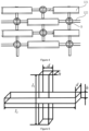
Fig. 2 is a schematic structural view of a radar support provided by an embodiment of the present invention; -
Fig. 3 is a schematic view of the C-C section of the radar support inFig. 2 after being mounted to a bumper skin; -
Fig. 4 is an enlarged view of the A part ofFig. 2 ; -
Fig. 5 is a schematic structural view of a crisscross rib provided by an embodiment of the present invention. - Preferred embodiments of the present invention are provided and described in detail below in reference to the accompanying drawings.
- As shown in
Figs. 2 and 3 , an embodiment of the present invention provides a radar support comprising a support body 11 provided with aradar fitting aperture 111 for mounting a radar. Awelding part 12 is provided at the periphery of the support body 11. As shown in the figures, thewelding part 12 can be provided respectively at left and right sides of the support body 11. Thewelding part 12 is provided with a welding region. The radar support is fixedly connected to abumper skin 2 by welding in the welding region. Thewelding part 12 has a plurality ofbuffer apertures 121 spaced apart from each other. Acrisscross rib 122 is arranged between twoadjacent buffer apertures 121. Thewelding part 12 is symmetrically arranged at both sides of the support body 11 with symmetric configurations of thebuffer apertures 121 and thecrisscross ribs 122. During welding, the solder joints are set on thecrisscross ribs 122 and can be located at any position of thecrisscross ribs 122. Thus, it can be ensured that during welding, the weld heads are welded on thecrisscross ribs 122 and the amount of molten welding material can be increased, thereby improving the welding tensile (pull-out) force so that it meets requirements. As the radar support is heated and expands during welding, its size will increase. After it cools down, contraction stress will appear, causing thebumper skin 2 to deform. By setting thebuffer apertures 121, each crisscross rib 122 (thus its associated solder joint) on the radar support is independent and disconnected from each other. When the radar support expands and deforms by heating during welding, thebuffer apertures 121 provide a space for deformation, so that the entire radar support will hardly undergo thermal expansion and deformation, thus eliminating thermal expansion and contraction stress and thereby eliminating welding marks. In other words, the expansion during the welding and heating process and the subsequent contraction of the radar support are scattered as local and disconnected, which can be absorbed by the corresponding buffer apertures locally one by one without causing any general or overall deformation to the radar support. - As shown in
Fig. 4 , a solder joint B can preferably be arranged at the center of acrisscross rib 122. Thus, it can expand and deform uniformly towards the buffer apertures on two sides when it is heated and expands, avoiding two adjacent solder joints B being too close to each other and affecting each other, which will lead to thermal expansion and deformation of the radar support as a whole, resulting in welding marks. - Also as shown in
Fig. 4 , thebuffer apertures 121 are of essentially a same shape and size, and distributed in a mesh structure with a essentially uniform transversal and longitudinal spacing between each other. Preferentially, thecrisscross rib 122 is arranged both between twoadjacent buffer apertures 121 along a transversal direction and between twoadjacent buffer apertures 121 along a longitudinal direction perpendicular to the transversal direction. - The
buffer apertures 121 can be provided in the shape of a rectangle, square, oval or any other appropriate form, which is not limited by the present invention. In the present embodiment, thebuffer apertures 121 are in the shape of a rectangle. It can be provided that their length, width, and height are respectively 4.5 to 5 mm, 0.6 to 1 mm, and 1.0 to 1.5 mm. As rectangular apertures are easy to process, preferably, buffer apertures are rectangular. - The spacing distance between
adjacent buffer apertures 121 can be set according to the spacing between welding teeth of a welding head and be kept consistent with the spacing between welding teeth. For example, in the present embodiment, the transversal spacing betweenadjacent buffer apertures 121 is 3 to 4 mm, and the longitudinal spacing is 2.5 to 3.5 mm, preferably, the transversal spacing is 3.3 mm, and the longitudinal spacing is 2.8 mm. It should be noted that, if the spacing betweenbuffer apertures 121 has already been set, the spacing between welding teeth can also be set according to the spacing betweenbuffer apertures 121 so as to keep the two consistent. - As shown in
Fig. 5 , the longitudinal length l1 and transversal length l2 of thecrisscross ribs 122 are respectively equal to the longitudinal spacing and transversal spacing between thebuffer apertures 121, while the height h and width d of thecrisscross ribs 122 can be adjusted according to the welding tensile force required. In the present embodiment, their height h is 0.3 mm, and their width d is 0.3 to 0.5 mm. When the welding tensile force required is relatively large, the width d can be set to 0.5 mm. - The support body 11, the
welding part 12, thebuffer apertures 121, and thecrisscross ribs 122 are formed integrally by injection molding in one piece, so that they are easier to process and the costs are reduced. - When calibrating the solder equipment before welding, the position of welding teeth of a welding head needs to be adjusted according to the position of the
buffer apertures 121 so that the welding teeth are accurately located on thecrisscross ribs 122, preferably at the center of thecrisscross ribs 122. Thus, not only more molten material can be created when welding the radar support, increasing the welding tensile force, but also the spacing distance between two solder joints can be sufficiently large so that the entire radar support does not undergo deformation as a whole, thereby eliminating thermal expansion and contraction stress and thus solder marks. - It should be noted that the structure of the
buffer apertures 121 and thecrisscross ribs 122 of the present invention is not limited to a radar support, but can be adapted to all structures with penetration welding, such as an air curtain or a reinforcing support, which is not limited by the present invention. - In a preferred embodiment (not shown), the
buffer apertures 121 contain veil or thickness reduction material in its full or partial aperture area. - The radar support of the present invention, by setting a plurality of
crisscross ribs 122 on thewelding part 12 of the radar support, enables the weld heads to be welded onto thecrisscross ribs 122 during welding, thus increasing the quantity of the molten welding material and increasing the welding tensile force. By arranging thebuffer apertures 121 between the crisscross ribs, a deformation space is provided for the expansion of the radar support during the welding and heating process, so that the entire radar support hardly undergoes thermal expansion and deformation as a whole, thereby eliminating thermal expansion and contraction stress, and thereby eliminating welding marks. - What have been described above are only preferred embodiments of the present invention, and are not intended to limit the scope of the present invention. Various changes can also be made to the above-described embodiments of the present invention. That is, all simple and equivalent changes and modifications made according to the claims and description of the present invention application fall into the protection scope of the claims of the present invention patent. What is not described in detail in this invention is conventional technical content.
Claims (14)
- A support structure, configured to be welded to a vehicle body part (2), characterized in that, it comprises:- a support body (11), preferentially provided with a mounting means (111) for attaching a technical element;- a welding part (12), arranged at a periphery of the support body (11), including:wherein a solder joint between the support structure and the vehicle body part (2) is located on the crisscross rib (122).• a plurality of buffer apertures (121) spaced apart from each other,• a plurality of crisscross ribs (122), each crisscross rib being disconnected from each other and arranged between two adjacent buffer apertures (121),
- The support structure according to claim 1, wherein the solder joint is located at a center of the crisscross rib (122).
- The support structure according to any one of the precedent claims, wherein the buffer apertures (121) are of essentially a same shape and size, and distributed in a mesh structure with a essentially uniform transversal and longitudinal spacing between each other.
- The support structure according to the precedent claim, wherein the crisscross ribs (122) are arranged both between two adjacent buffer apertures (121) along a transversal direction and between two adjacent buffer apertures (121) along a longitudinal direction perpendicular to the transversal direction, wherein a longitudinal length (l1) and a transversal length (12) of the crisscross ribs (122) are respectively equal to the longitudinal spacing and the transversal spacing between the buffer apertures (121).
- The support structure according to any one of the precedent claims, wherein the welding part (12) is symmetrically arranged at both sides of the support body (11) with symmetric configurations of the buffer apertures (121) and the crisscross ribs (122).
- The support structure according to any one of the precedent claims, wherein the buffer apertures (121) contain veil or thickness reduction material in its full or partial aperture area.
- The support structure according to any one of the precedent claims, wherein the buffer apertures (121) are in a shape of a rectangle, a square, or an oval.
- The support structure according to any one of the precedent claims, wherein a transversal spacing between two adjacent buffer apertures (121) is 3 to 4 mm, and a longitudinal spacing between two adjacent buffer apertures (121) is 2.5 to 3.5 mm.
- The support structure according to the precedent claim, wherein the transversal spacing is 3.2 mm and the longitudinal spacing is 2.8 mm.
- The support structure according to claim 7, wherein the length, width, and height of the buffer apertures (121) are respectively 4.7 to 5 mm, 0.8 to 1 mm, and 1.2 to 1.5 mm.
- The support structure according to any one of the precedent claims, wherein the height (h) of the crisscross ribs (122) is 0.3 mm, and the width (d) of the crisscross ribs (122) is 0.3 to 0.5 mm.
- The support structure according to any one of the precedent claims, wherein the buffer apertures (121), the crisscross ribs (122), the welding part (12), and the support body (11) are integrally formed by injection molding.
- The support structure according to any one of the precedent claims, wherein the support structure is a radar support, an air curtain or a reinforcing support.
- Body part of a vehicle (2), for example a bumper skin (2), characterized in that, it comprises the support structure according to any one of the precedent claims.
Applications Claiming Priority (1)
| Application Number | Priority Date | Filing Date | Title |
|---|---|---|---|
| CN202123344114.2U CN216861397U (en) | 2021-12-28 | 2021-12-28 | Radar support |
Publications (2)
| Publication Number | Publication Date |
|---|---|
| EP4205951A1 true EP4205951A1 (en) | 2023-07-05 |
| EP4205951B1 EP4205951B1 (en) | 2024-10-16 |
Family
ID=81854812
Family Applications (1)
| Application Number | Title | Priority Date | Filing Date |
|---|---|---|---|
| EP22176383.2A Active EP4205951B1 (en) | 2021-12-28 | 2022-05-31 | A support structure |
Country Status (4)
| Country | Link |
|---|---|
| EP (1) | EP4205951B1 (en) |
| CN (1) | CN216861397U (en) |
| ES (1) | ES3010535T3 (en) |
| PL (1) | PL4205951T3 (en) |
Cited By (1)
| Publication number | Priority date | Publication date | Assignee | Title |
|---|---|---|---|---|
| CN116968675A (en) * | 2023-07-21 | 2023-10-31 | 东风汽车集团股份有限公司 | Parasitic plastic mounting bracket, front bumper, mold and manufacturing method |
Citations (1)
| Publication number | Priority date | Publication date | Assignee | Title |
|---|---|---|---|---|
| KR20120025831A (en) * | 2010-09-08 | 2012-03-16 | 장봉철 | Welding method of bumper fascia and holder bracket using ultrasonic vibration |
-
2021
- 2021-12-28 CN CN202123344114.2U patent/CN216861397U/en active Active
-
2022
- 2022-05-31 ES ES22176383T patent/ES3010535T3/en active Active
- 2022-05-31 EP EP22176383.2A patent/EP4205951B1/en active Active
- 2022-05-31 PL PL22176383.2T patent/PL4205951T3/en unknown
Patent Citations (1)
| Publication number | Priority date | Publication date | Assignee | Title |
|---|---|---|---|---|
| KR20120025831A (en) * | 2010-09-08 | 2012-03-16 | 장봉철 | Welding method of bumper fascia and holder bracket using ultrasonic vibration |
Cited By (1)
| Publication number | Priority date | Publication date | Assignee | Title |
|---|---|---|---|---|
| CN116968675A (en) * | 2023-07-21 | 2023-10-31 | 东风汽车集团股份有限公司 | Parasitic plastic mounting bracket, front bumper, mold and manufacturing method |
Also Published As
| Publication number | Publication date |
|---|---|
| CN216861397U (en) | 2022-07-01 |
| EP4205951B1 (en) | 2024-10-16 |
| PL4205951T3 (en) | 2025-03-17 |
| ES3010535T3 (en) | 2025-04-03 |
Similar Documents
| Publication | Publication Date | Title |
|---|---|---|
| KR102033645B1 (en) | Vehicle body structure | |
| EP4205951A1 (en) | A support structure | |
| ES2682041T3 (en) | IMPACT ABSORPTION BOX AND METHOD FOR MANUFACTURING THE SAME | |
| JP5603182B2 (en) | Spoiler | |
| JP6530822B2 (en) | Skeletal structure and vehicle seat | |
| US20130193716A1 (en) | Vehicle body structure | |
| US10479429B2 (en) | Process for manufacturing bumper reinforcement | |
| JP6239124B2 (en) | Body structure | |
| JP2009521368A (en) | Vehicle bumper beam made of metal and plastic | |
| ES2970634T3 (en) | Union structure and method of manufacturing it | |
| BR112019024605B1 (en) | VEHICLE PANEL AND MANUFACTURING METHOD | |
| JPS60232185A (en) | Ski edge and its production | |
| KR102325352B1 (en) | Range of at least two types of motor vehicle comprising a sheet metal roof or a glass roof | |
| JP6066303B2 (en) | Roof front inner panel structure | |
| JP2020189505A (en) | Manufacturing method of side door for vehicle, component for door and side door | |
| JP4210834B2 (en) | Resin fender panel position adjustment method and resin fender panel position adjustment structure | |
| JP6141789B2 (en) | Vehicle roof reinforcement | |
| JP2018052428A (en) | Door impact beam | |
| CN216034705U (en) | Automobile upper side beam structure | |
| JP2016002788A (en) | Body side structure | |
| JP6975891B2 (en) | Manufacturing method of resin panel for vehicles and resin panel for vehicles | |
| DE102019114335B4 (en) | Fender structure for a vehicle | |
| KR200153663Y1 (en) | Rocker panel of vehicle | |
| CN220742956U (en) | Large-angle bending structure of straight section bar | |
| CN222372981U (en) | Front upper component connection structure and vehicle |
Legal Events
| Date | Code | Title | Description |
|---|---|---|---|
| PUAI | Public reference made under article 153(3) epc to a published international application that has entered the european phase |
Free format text: ORIGINAL CODE: 0009012 |
|
| STAA | Information on the status of an ep patent application or granted ep patent |
Free format text: STATUS: THE APPLICATION HAS BEEN PUBLISHED |
|
| AK | Designated contracting states |
Kind code of ref document: A1 Designated state(s): AL AT BE BG CH CY CZ DE DK EE ES FI FR GB GR HR HU IE IS IT LI LT LU LV MC MK MT NL NO PL PT RO RS SE SI SK SM TR |
|
| STAA | Information on the status of an ep patent application or granted ep patent |
Free format text: STATUS: REQUEST FOR EXAMINATION WAS MADE |
|
| 17P | Request for examination filed |
Effective date: 20231226 |
|
| RBV | Designated contracting states (corrected) |
Designated state(s): AL AT BE BG CH CY CZ DE DK EE ES FI FR GB GR HR HU IE IS IT LI LT LU LV MC MK MT NL NO PL PT RO RS SE SI SK SM TR |
|
| GRAP | Despatch of communication of intention to grant a patent |
Free format text: ORIGINAL CODE: EPIDOSNIGR1 |
|
| STAA | Information on the status of an ep patent application or granted ep patent |
Free format text: STATUS: GRANT OF PATENT IS INTENDED |
|
| RIC1 | Information provided on ipc code assigned before grant |
Ipc: B60R 19/48 20060101ALN20240425BHEP Ipc: B60R 19/02 20060101ALN20240425BHEP Ipc: B29L 31/30 20060101ALN20240425BHEP Ipc: G01S 7/02 20060101ALI20240425BHEP Ipc: G01S 13/931 20200101ALI20240425BHEP Ipc: B29C 65/02 20060101AFI20240425BHEP |
|
| INTG | Intention to grant announced |
Effective date: 20240529 |
|
| RAP3 | Party data changed (applicant data changed or rights of an application transferred) |
Owner name: OPMOBILITY SE Owner name: YANFENG PLASTIC OMNIUMAUTOMOTIVE EXTERIOR SYSTEMS CO., LTD. |
|
| RAP3 | Party data changed (applicant data changed or rights of an application transferred) |
Owner name: OPMOBILITY SE Owner name: YANFENG PLASTIC OMNIUMAUTOMOTIVE EXTERIOR SYSTEMS CO., LTD. |
|
| GRAS | Grant fee paid |
Free format text: ORIGINAL CODE: EPIDOSNIGR3 |
|
| GRAA | (expected) grant |
Free format text: ORIGINAL CODE: 0009210 |
|
| STAA | Information on the status of an ep patent application or granted ep patent |
Free format text: STATUS: THE PATENT HAS BEEN GRANTED |
|
| AK | Designated contracting states |
Kind code of ref document: B1 Designated state(s): AL AT BE BG CH CY CZ DE DK EE ES FI FR GB GR HR HU IE IS IT LI LT LU LV MC MK MT NL NO PL PT RO RS SE SI SK SM TR |
|
| REG | Reference to a national code |
Ref country code: GB Ref legal event code: FG4D |
|
| REG | Reference to a national code |
Ref country code: CH Ref legal event code: EP Ref country code: DE Ref legal event code: R096 Ref document number: 602022006795 Country of ref document: DE |
|
| REG | Reference to a national code |
Ref country code: IE Ref legal event code: FG4D |
|
| P01 | Opt-out of the competence of the unified patent court (upc) registered |
Free format text: CASE NUMBER: APP_55060/2024 Effective date: 20241007 |
|
| REG | Reference to a national code |
Ref country code: SE Ref legal event code: TRGR |
|
| REG | Reference to a national code |
Ref country code: LT Ref legal event code: MG9D |
|
| REG | Reference to a national code |
Ref country code: NL Ref legal event code: MP Effective date: 20241016 |
|
| REG | Reference to a national code |
Ref country code: SK Ref legal event code: T3 Ref document number: E 45721 Country of ref document: SK |
|
| REG | Reference to a national code |
Ref country code: AT Ref legal event code: MK05 Ref document number: 1732612 Country of ref document: AT Kind code of ref document: T Effective date: 20241016 |
|
| PG25 | Lapsed in a contracting state [announced via postgrant information from national office to epo] |
Ref country code: NL Free format text: LAPSE BECAUSE OF FAILURE TO SUBMIT A TRANSLATION OF THE DESCRIPTION OR TO PAY THE FEE WITHIN THE PRESCRIBED TIME-LIMIT Effective date: 20241016 |
|
| PG25 | Lapsed in a contracting state [announced via postgrant information from national office to epo] |
Ref country code: NL Free format text: LAPSE BECAUSE OF FAILURE TO SUBMIT A TRANSLATION OF THE DESCRIPTION OR TO PAY THE FEE WITHIN THE PRESCRIBED TIME-LIMIT Effective date: 20241016 |
|
| PG25 | Lapsed in a contracting state [announced via postgrant information from national office to epo] |
Ref country code: IS Free format text: LAPSE BECAUSE OF FAILURE TO SUBMIT A TRANSLATION OF THE DESCRIPTION OR TO PAY THE FEE WITHIN THE PRESCRIBED TIME-LIMIT Effective date: 20250216 Ref country code: HR Free format text: LAPSE BECAUSE OF FAILURE TO SUBMIT A TRANSLATION OF THE DESCRIPTION OR TO PAY THE FEE WITHIN THE PRESCRIBED TIME-LIMIT Effective date: 20241016 Ref country code: PT Free format text: LAPSE BECAUSE OF FAILURE TO SUBMIT A TRANSLATION OF THE DESCRIPTION OR TO PAY THE FEE WITHIN THE PRESCRIBED TIME-LIMIT Effective date: 20250217 |
|
| PG25 | Lapsed in a contracting state [announced via postgrant information from national office to epo] |
Ref country code: FI Free format text: LAPSE BECAUSE OF FAILURE TO SUBMIT A TRANSLATION OF THE DESCRIPTION OR TO PAY THE FEE WITHIN THE PRESCRIBED TIME-LIMIT Effective date: 20241016 |
|
| PG25 | Lapsed in a contracting state [announced via postgrant information from national office to epo] |
Ref country code: BG Free format text: LAPSE BECAUSE OF FAILURE TO SUBMIT A TRANSLATION OF THE DESCRIPTION OR TO PAY THE FEE WITHIN THE PRESCRIBED TIME-LIMIT Effective date: 20241016 |
|
| PG25 | Lapsed in a contracting state [announced via postgrant information from national office to epo] |
Ref country code: NO Free format text: LAPSE BECAUSE OF FAILURE TO SUBMIT A TRANSLATION OF THE DESCRIPTION OR TO PAY THE FEE WITHIN THE PRESCRIBED TIME-LIMIT Effective date: 20250116 |
|
| PG25 | Lapsed in a contracting state [announced via postgrant information from national office to epo] |
Ref country code: LV Free format text: LAPSE BECAUSE OF FAILURE TO SUBMIT A TRANSLATION OF THE DESCRIPTION OR TO PAY THE FEE WITHIN THE PRESCRIBED TIME-LIMIT Effective date: 20241016 Ref country code: AT Free format text: LAPSE BECAUSE OF FAILURE TO SUBMIT A TRANSLATION OF THE DESCRIPTION OR TO PAY THE FEE WITHIN THE PRESCRIBED TIME-LIMIT Effective date: 20241016 Ref country code: GR Free format text: LAPSE BECAUSE OF FAILURE TO SUBMIT A TRANSLATION OF THE DESCRIPTION OR TO PAY THE FEE WITHIN THE PRESCRIBED TIME-LIMIT Effective date: 20250117 |
|
| PG25 | Lapsed in a contracting state [announced via postgrant information from national office to epo] |
Ref country code: RS Free format text: LAPSE BECAUSE OF FAILURE TO SUBMIT A TRANSLATION OF THE DESCRIPTION OR TO PAY THE FEE WITHIN THE PRESCRIBED TIME-LIMIT Effective date: 20250116 |
|
| PG25 | Lapsed in a contracting state [announced via postgrant information from national office to epo] |
Ref country code: SM Free format text: LAPSE BECAUSE OF FAILURE TO SUBMIT A TRANSLATION OF THE DESCRIPTION OR TO PAY THE FEE WITHIN THE PRESCRIBED TIME-LIMIT Effective date: 20241016 |
|
| PGFP | Annual fee paid to national office [announced via postgrant information from national office to epo] |
Ref country code: PL Payment date: 20250422 Year of fee payment: 4 Ref country code: DE Payment date: 20250521 Year of fee payment: 4 |
|
| PG25 | Lapsed in a contracting state [announced via postgrant information from national office to epo] |
Ref country code: DK Free format text: LAPSE BECAUSE OF FAILURE TO SUBMIT A TRANSLATION OF THE DESCRIPTION OR TO PAY THE FEE WITHIN THE PRESCRIBED TIME-LIMIT Effective date: 20241016 |
|
| PGFP | Annual fee paid to national office [announced via postgrant information from national office to epo] |
Ref country code: IT Payment date: 20250531 Year of fee payment: 4 |
|
| REG | Reference to a national code |
Ref country code: DE Ref legal event code: R097 Ref document number: 602022006795 Country of ref document: DE |
|
| PG25 | Lapsed in a contracting state [announced via postgrant information from national office to epo] |
Ref country code: EE Free format text: LAPSE BECAUSE OF FAILURE TO SUBMIT A TRANSLATION OF THE DESCRIPTION OR TO PAY THE FEE WITHIN THE PRESCRIBED TIME-LIMIT Effective date: 20241016 |
|
| PGFP | Annual fee paid to national office [announced via postgrant information from national office to epo] |
Ref country code: FR Payment date: 20250530 Year of fee payment: 4 |
|
| PG25 | Lapsed in a contracting state [announced via postgrant information from national office to epo] |
Ref country code: RO Free format text: LAPSE BECAUSE OF FAILURE TO SUBMIT A TRANSLATION OF THE DESCRIPTION OR TO PAY THE FEE WITHIN THE PRESCRIBED TIME-LIMIT Effective date: 20241016 |
|
| PGFP | Annual fee paid to national office [announced via postgrant information from national office to epo] |
Ref country code: SK Payment date: 20250527 Year of fee payment: 4 |
|
| PGFP | Annual fee paid to national office [announced via postgrant information from national office to epo] |
Ref country code: CZ Payment date: 20250523 Year of fee payment: 4 |
|
| PGFP | Annual fee paid to national office [announced via postgrant information from national office to epo] |
Ref country code: SE Payment date: 20250521 Year of fee payment: 4 |
|
| PLBE | No opposition filed within time limit |
Free format text: ORIGINAL CODE: 0009261 |
|
| STAA | Information on the status of an ep patent application or granted ep patent |
Free format text: STATUS: NO OPPOSITION FILED WITHIN TIME LIMIT |
|
| 26N | No opposition filed |
Effective date: 20250717 |
|
| PGFP | Annual fee paid to national office [announced via postgrant information from national office to epo] |
Ref country code: ES Payment date: 20250630 Year of fee payment: 4 |
|
| REG | Reference to a national code |
Ref country code: CH Ref legal event code: H13 Free format text: ST27 STATUS EVENT CODE: U-0-0-H10-H13 (AS PROVIDED BY THE NATIONAL OFFICE) Effective date: 20251223 |
|
| PG25 | Lapsed in a contracting state [announced via postgrant information from national office to epo] |
Ref country code: LU Free format text: LAPSE BECAUSE OF NON-PAYMENT OF DUE FEES Effective date: 20250531 |
|
| PG25 | Lapsed in a contracting state [announced via postgrant information from national office to epo] |
Ref country code: CH Free format text: LAPSE BECAUSE OF NON-PAYMENT OF DUE FEES Effective date: 20250531 |
|
| REG | Reference to a national code |
Ref country code: BE Ref legal event code: MM Effective date: 20250531 |
|
| PG25 | Lapsed in a contracting state [announced via postgrant information from national office to epo] |
Ref country code: MC Free format text: LAPSE BECAUSE OF FAILURE TO SUBMIT A TRANSLATION OF THE DESCRIPTION OR TO PAY THE FEE WITHIN THE PRESCRIBED TIME-LIMIT Effective date: 20241016 |
|
| PG25 | Lapsed in a contracting state [announced via postgrant information from national office to epo] |
Ref country code: IE Free format text: LAPSE BECAUSE OF NON-PAYMENT OF DUE FEES Effective date: 20250531 |
|
| PG25 | Lapsed in a contracting state [announced via postgrant information from national office to epo] |
Ref country code: BE Free format text: LAPSE BECAUSE OF NON-PAYMENT OF DUE FEES Effective date: 20250531 |