EP4205852A1 - System and method for retrieving and analyzing particles - Google Patents
System and method for retrieving and analyzing particles Download PDFInfo
- Publication number
- EP4205852A1 EP4205852A1 EP23156657.1A EP23156657A EP4205852A1 EP 4205852 A1 EP4205852 A1 EP 4205852A1 EP 23156657 A EP23156657 A EP 23156657A EP 4205852 A1 EP4205852 A1 EP 4205852A1
- Authority
- EP
- European Patent Office
- Prior art keywords
- subsystem
- cell
- particle
- substrate
- extractor
- Prior art date
- Legal status (The legal status is an assumption and is not a legal conclusion. Google has not performed a legal analysis and makes no representation as to the accuracy of the status listed.)
- Pending
Links
- 238000000034 method Methods 0.000 title abstract description 40
- 239000002245 particle Substances 0.000 title description 197
- 239000000758 substrate Substances 0.000 claims abstract description 98
- 238000003384 imaging method Methods 0.000 claims description 59
- 230000003287 optical effect Effects 0.000 claims description 45
- 239000011800 void material Substances 0.000 claims description 14
- 238000005286 illumination Methods 0.000 claims description 12
- 238000012545 processing Methods 0.000 claims description 9
- 238000004891 communication Methods 0.000 claims description 7
- 239000000463 material Substances 0.000 claims description 6
- 238000000799 fluorescence microscopy Methods 0.000 claims description 5
- 230000006378 damage Effects 0.000 claims description 2
- 239000012530 fluid Substances 0.000 abstract description 15
- 210000004027 cell Anatomy 0.000 description 217
- 230000033001 locomotion Effects 0.000 description 27
- 230000006870 function Effects 0.000 description 21
- 238000000605 extraction Methods 0.000 description 18
- 238000013519 translation Methods 0.000 description 14
- 238000003780 insertion Methods 0.000 description 12
- 230000037431 insertion Effects 0.000 description 12
- 239000003153 chemical reaction reagent Substances 0.000 description 10
- 238000004458 analytical method Methods 0.000 description 9
- 230000005284 excitation Effects 0.000 description 6
- 238000005086 pumping Methods 0.000 description 6
- 230000007246 mechanism Effects 0.000 description 5
- 230000008901 benefit Effects 0.000 description 4
- 230000000717 retained effect Effects 0.000 description 4
- 230000005540 biological transmission Effects 0.000 description 3
- 230000001413 cellular effect Effects 0.000 description 3
- 238000010586 diagram Methods 0.000 description 3
- 238000005530 etching Methods 0.000 description 3
- 238000000684 flow cytometry Methods 0.000 description 3
- 238000002360 preparation method Methods 0.000 description 3
- 108091033409 CRISPR Proteins 0.000 description 2
- 238000010354 CRISPR gene editing Methods 0.000 description 2
- 230000009471 action Effects 0.000 description 2
- 238000003556 assay Methods 0.000 description 2
- 230000005779 cell damage Effects 0.000 description 2
- 208000037887 cell injury Diseases 0.000 description 2
- 238000004140 cleaning Methods 0.000 description 2
- 230000008878 coupling Effects 0.000 description 2
- 238000010168 coupling process Methods 0.000 description 2
- 238000005859 coupling reaction Methods 0.000 description 2
- 238000012258 culturing Methods 0.000 description 2
- 238000000708 deep reactive-ion etching Methods 0.000 description 2
- 238000006073 displacement reaction Methods 0.000 description 2
- 239000011521 glass Substances 0.000 description 2
- 230000005484 gravity Effects 0.000 description 2
- 238000002955 isolation Methods 0.000 description 2
- 230000000670 limiting effect Effects 0.000 description 2
- 239000007788 liquid Substances 0.000 description 2
- 238000004519 manufacturing process Methods 0.000 description 2
- 239000002184 metal Substances 0.000 description 2
- 229910052751 metal Inorganic materials 0.000 description 2
- 229920000642 polymer Polymers 0.000 description 2
- 238000003825 pressing Methods 0.000 description 2
- 230000037452 priming Effects 0.000 description 2
- 230000004044 response Effects 0.000 description 2
- 238000001228 spectrum Methods 0.000 description 2
- 238000010186 staining Methods 0.000 description 2
- 230000000007 visual effect Effects 0.000 description 2
- RYGMFSIKBFXOCR-UHFFFAOYSA-N Copper Chemical compound [Cu] RYGMFSIKBFXOCR-UHFFFAOYSA-N 0.000 description 1
- 239000004698 Polyethylene Substances 0.000 description 1
- 229910000831 Steel Inorganic materials 0.000 description 1
- 239000004809 Teflon Substances 0.000 description 1
- 229920006362 Teflon® Polymers 0.000 description 1
- 230000004913 activation Effects 0.000 description 1
- 238000013019 agitation Methods 0.000 description 1
- 239000000427 antigen Substances 0.000 description 1
- 102000036639 antigens Human genes 0.000 description 1
- 108091007433 antigens Proteins 0.000 description 1
- 230000015572 biosynthetic process Effects 0.000 description 1
- 238000000339 bright-field microscopy Methods 0.000 description 1
- 230000003833 cell viability Effects 0.000 description 1
- HGAZMNJKRQFZKS-UHFFFAOYSA-N chloroethene;ethenyl acetate Chemical compound ClC=C.CC(=O)OC=C HGAZMNJKRQFZKS-UHFFFAOYSA-N 0.000 description 1
- 239000011248 coating agent Substances 0.000 description 1
- 238000000576 coating method Methods 0.000 description 1
- 230000000295 complement effect Effects 0.000 description 1
- 238000004590 computer program Methods 0.000 description 1
- 229910052802 copper Inorganic materials 0.000 description 1
- 239000010949 copper Substances 0.000 description 1
- 210000000172 cytosol Anatomy 0.000 description 1
- 238000013500 data storage Methods 0.000 description 1
- 238000001514 detection method Methods 0.000 description 1
- 238000003745 diagnosis Methods 0.000 description 1
- 239000003814 drug Substances 0.000 description 1
- 238000003255 drug test Methods 0.000 description 1
- 230000000694 effects Effects 0.000 description 1
- 238000005516 engineering process Methods 0.000 description 1
- 239000000284 extract Substances 0.000 description 1
- 239000000945 filler Substances 0.000 description 1
- 238000010438 heat treatment Methods 0.000 description 1
- 238000010191 image analysis Methods 0.000 description 1
- 238000002347 injection Methods 0.000 description 1
- 239000007924 injection Substances 0.000 description 1
- 230000007762 localization of cell Effects 0.000 description 1
- 238000001000 micrograph Methods 0.000 description 1
- 238000012986 modification Methods 0.000 description 1
- 230000004048 modification Effects 0.000 description 1
- 238000012544 monitoring process Methods 0.000 description 1
- 238000007837 multiplex assay Methods 0.000 description 1
- 230000036961 partial effect Effects 0.000 description 1
- 230000008823 permeabilization Effects 0.000 description 1
- 238000001020 plasma etching Methods 0.000 description 1
- 239000004033 plastic Substances 0.000 description 1
- 229920003023 plastic Polymers 0.000 description 1
- -1 polyethylene Polymers 0.000 description 1
- 229920000573 polyethylene Polymers 0.000 description 1
- 230000008569 process Effects 0.000 description 1
- 230000001681 protective effect Effects 0.000 description 1
- 230000002829 reductive effect Effects 0.000 description 1
- 238000009877 rendering Methods 0.000 description 1
- 230000002441 reversible effect Effects 0.000 description 1
- 238000007789 sealing Methods 0.000 description 1
- 229910052710 silicon Inorganic materials 0.000 description 1
- 239000010703 silicon Substances 0.000 description 1
- 239000010959 steel Substances 0.000 description 1
- 238000012360 testing method Methods 0.000 description 1
- 239000012780 transparent material Substances 0.000 description 1
- 238000005406 washing Methods 0.000 description 1
Images


Classifications
-
- C—CHEMISTRY; METALLURGY
- C12—BIOCHEMISTRY; BEER; SPIRITS; WINE; VINEGAR; MICROBIOLOGY; ENZYMOLOGY; MUTATION OR GENETIC ENGINEERING
- C12M—APPARATUS FOR ENZYMOLOGY OR MICROBIOLOGY; APPARATUS FOR CULTURING MICROORGANISMS FOR PRODUCING BIOMASS, FOR GROWING CELLS OR FOR OBTAINING FERMENTATION OR METABOLIC PRODUCTS, i.e. BIOREACTORS OR FERMENTERS
- C12M23/00—Constructional details, e.g. recesses, hinges
- C12M23/02—Form or structure of the vessel
- C12M23/12—Well or multiwell plates
-
- G—PHYSICS
- G01—MEASURING; TESTING
- G01N—INVESTIGATING OR ANALYSING MATERIALS BY DETERMINING THEIR CHEMICAL OR PHYSICAL PROPERTIES
- G01N21/00—Investigating or analysing materials by the use of optical means, i.e. using sub-millimetre waves, infrared, visible or ultraviolet light
- G01N21/62—Systems in which the material investigated is excited whereby it emits light or causes a change in wavelength of the incident light
- G01N21/63—Systems in which the material investigated is excited whereby it emits light or causes a change in wavelength of the incident light optically excited
- G01N21/64—Fluorescence; Phosphorescence
- G01N21/645—Specially adapted constructive features of fluorimeters
- G01N21/6456—Spatial resolved fluorescence measurements; Imaging
- G01N21/6458—Fluorescence microscopy
-
- B—PERFORMING OPERATIONS; TRANSPORTING
- B01—PHYSICAL OR CHEMICAL PROCESSES OR APPARATUS IN GENERAL
- B01L—CHEMICAL OR PHYSICAL LABORATORY APPARATUS FOR GENERAL USE
- B01L3/00—Containers or dishes for laboratory use, e.g. laboratory glassware; Droppers
- B01L3/50—Containers for the purpose of retaining a material to be analysed, e.g. test tubes
- B01L3/502—Containers for the purpose of retaining a material to be analysed, e.g. test tubes with fluid transport, e.g. in multi-compartment structures
- B01L3/5027—Containers for the purpose of retaining a material to be analysed, e.g. test tubes with fluid transport, e.g. in multi-compartment structures by integrated microfluidic structures, i.e. dimensions of channels and chambers are such that surface tension forces are important, e.g. lab-on-a-chip
- B01L3/502761—Containers for the purpose of retaining a material to be analysed, e.g. test tubes with fluid transport, e.g. in multi-compartment structures by integrated microfluidic structures, i.e. dimensions of channels and chambers are such that surface tension forces are important, e.g. lab-on-a-chip specially adapted for handling suspended solids or molecules independently from the bulk fluid flow, e.g. for trapping or sorting beads, for physically stretching molecules
-
- B—PERFORMING OPERATIONS; TRANSPORTING
- B01—PHYSICAL OR CHEMICAL PROCESSES OR APPARATUS IN GENERAL
- B01L—CHEMICAL OR PHYSICAL LABORATORY APPARATUS FOR GENERAL USE
- B01L3/00—Containers or dishes for laboratory use, e.g. laboratory glassware; Droppers
- B01L3/50—Containers for the purpose of retaining a material to be analysed, e.g. test tubes
- B01L3/508—Containers for the purpose of retaining a material to be analysed, e.g. test tubes rigid containers not provided for above
- B01L3/5085—Containers for the purpose of retaining a material to be analysed, e.g. test tubes rigid containers not provided for above for multiple samples, e.g. microtitration plates
-
- C—CHEMISTRY; METALLURGY
- C12—BIOCHEMISTRY; BEER; SPIRITS; WINE; VINEGAR; MICROBIOLOGY; ENZYMOLOGY; MUTATION OR GENETIC ENGINEERING
- C12M—APPARATUS FOR ENZYMOLOGY OR MICROBIOLOGY; APPARATUS FOR CULTURING MICROORGANISMS FOR PRODUCING BIOMASS, FOR GROWING CELLS OR FOR OBTAINING FERMENTATION OR METABOLIC PRODUCTS, i.e. BIOREACTORS OR FERMENTERS
- C12M33/00—Means for introduction, transport, positioning, extraction, harvesting, peeling or sampling of biological material in or from the apparatus
- C12M33/04—Means for introduction, transport, positioning, extraction, harvesting, peeling or sampling of biological material in or from the apparatus by injection or suction, e.g. using pipettes, syringes, needles
-
- C—CHEMISTRY; METALLURGY
- C12—BIOCHEMISTRY; BEER; SPIRITS; WINE; VINEGAR; MICROBIOLOGY; ENZYMOLOGY; MUTATION OR GENETIC ENGINEERING
- C12M—APPARATUS FOR ENZYMOLOGY OR MICROBIOLOGY; APPARATUS FOR CULTURING MICROORGANISMS FOR PRODUCING BIOMASS, FOR GROWING CELLS OR FOR OBTAINING FERMENTATION OR METABOLIC PRODUCTS, i.e. BIOREACTORS OR FERMENTERS
- C12M41/00—Means for regulation, monitoring, measurement or control, e.g. flow regulation
- C12M41/30—Means for regulation, monitoring, measurement or control, e.g. flow regulation of concentration
- C12M41/36—Means for regulation, monitoring, measurement or control, e.g. flow regulation of concentration of biomass, e.g. colony counters or by turbidity measurements
-
- C—CHEMISTRY; METALLURGY
- C12—BIOCHEMISTRY; BEER; SPIRITS; WINE; VINEGAR; MICROBIOLOGY; ENZYMOLOGY; MUTATION OR GENETIC ENGINEERING
- C12M—APPARATUS FOR ENZYMOLOGY OR MICROBIOLOGY; APPARATUS FOR CULTURING MICROORGANISMS FOR PRODUCING BIOMASS, FOR GROWING CELLS OR FOR OBTAINING FERMENTATION OR METABOLIC PRODUCTS, i.e. BIOREACTORS OR FERMENTERS
- C12M41/00—Means for regulation, monitoring, measurement or control, e.g. flow regulation
- C12M41/48—Automatic or computerized control
-
- C—CHEMISTRY; METALLURGY
- C12—BIOCHEMISTRY; BEER; SPIRITS; WINE; VINEGAR; MICROBIOLOGY; ENZYMOLOGY; MUTATION OR GENETIC ENGINEERING
- C12M—APPARATUS FOR ENZYMOLOGY OR MICROBIOLOGY; APPARATUS FOR CULTURING MICROORGANISMS FOR PRODUCING BIOMASS, FOR GROWING CELLS OR FOR OBTAINING FERMENTATION OR METABOLIC PRODUCTS, i.e. BIOREACTORS OR FERMENTERS
- C12M47/00—Means for after-treatment of the produced biomass or of the fermentation or metabolic products, e.g. storage of biomass
- C12M47/04—Cell isolation or sorting
-
- G—PHYSICS
- G01—MEASURING; TESTING
- G01N—INVESTIGATING OR ANALYSING MATERIALS BY DETERMINING THEIR CHEMICAL OR PHYSICAL PROPERTIES
- G01N1/00—Sampling; Preparing specimens for investigation
- G01N1/28—Preparing specimens for investigation including physical details of (bio-)chemical methods covered elsewhere, e.g. G01N33/50, C12Q
- G01N1/40—Concentrating samples
- G01N1/4077—Concentrating samples by other techniques involving separation of suspended solids
-
- G—PHYSICS
- G01—MEASURING; TESTING
- G01N—INVESTIGATING OR ANALYSING MATERIALS BY DETERMINING THEIR CHEMICAL OR PHYSICAL PROPERTIES
- G01N15/00—Investigating characteristics of particles; Investigating permeability, pore-volume, or surface-area of porous materials
- G01N15/02—Investigating particle size or size distribution
-
- G01N15/1433—
-
- G—PHYSICS
- G01—MEASURING; TESTING
- G01N—INVESTIGATING OR ANALYSING MATERIALS BY DETERMINING THEIR CHEMICAL OR PHYSICAL PROPERTIES
- G01N15/00—Investigating characteristics of particles; Investigating permeability, pore-volume, or surface-area of porous materials
- G01N15/10—Investigating individual particles
- G01N15/14—Electro-optical investigation, e.g. flow cytometers
- G01N15/1468—Electro-optical investigation, e.g. flow cytometers with spatial resolution of the texture or inner structure of the particle
-
- G—PHYSICS
- G01—MEASURING; TESTING
- G01N—INVESTIGATING OR ANALYSING MATERIALS BY DETERMINING THEIR CHEMICAL OR PHYSICAL PROPERTIES
- G01N15/00—Investigating characteristics of particles; Investigating permeability, pore-volume, or surface-area of porous materials
- G01N15/10—Investigating individual particles
- G01N15/14—Electro-optical investigation, e.g. flow cytometers
- G01N15/1484—Electro-optical investigation, e.g. flow cytometers microstructural devices
-
- G—PHYSICS
- G01—MEASURING; TESTING
- G01N—INVESTIGATING OR ANALYSING MATERIALS BY DETERMINING THEIR CHEMICAL OR PHYSICAL PROPERTIES
- G01N21/00—Investigating or analysing materials by the use of optical means, i.e. using sub-millimetre waves, infrared, visible or ultraviolet light
- G01N21/84—Systems specially adapted for particular applications
-
- G—PHYSICS
- G01—MEASURING; TESTING
- G01N—INVESTIGATING OR ANALYSING MATERIALS BY DETERMINING THEIR CHEMICAL OR PHYSICAL PROPERTIES
- G01N35/00—Automatic analysis not limited to methods or materials provided for in any single one of groups G01N1/00 - G01N33/00; Handling materials therefor
- G01N35/00029—Automatic analysis not limited to methods or materials provided for in any single one of groups G01N1/00 - G01N33/00; Handling materials therefor provided with flat sample substrates, e.g. slides
-
- G—PHYSICS
- G01—MEASURING; TESTING
- G01N—INVESTIGATING OR ANALYSING MATERIALS BY DETERMINING THEIR CHEMICAL OR PHYSICAL PROPERTIES
- G01N35/00—Automatic analysis not limited to methods or materials provided for in any single one of groups G01N1/00 - G01N33/00; Handling materials therefor
- G01N35/10—Devices for transferring samples or any liquids to, in, or from, the analysis apparatus, e.g. suction devices, injection devices
- G01N35/1009—Characterised by arrangements for controlling the aspiration or dispense of liquids
- G01N35/1011—Control of the position or alignment of the transfer device
-
- B—PERFORMING OPERATIONS; TRANSPORTING
- B01—PHYSICAL OR CHEMICAL PROCESSES OR APPARATUS IN GENERAL
- B01L—CHEMICAL OR PHYSICAL LABORATORY APPARATUS FOR GENERAL USE
- B01L2200/00—Solutions for specific problems relating to chemical or physical laboratory apparatus
- B01L2200/06—Fluid handling related problems
- B01L2200/0647—Handling flowable solids, e.g. microscopic beads, cells, particles
- B01L2200/0668—Trapping microscopic beads
-
- B—PERFORMING OPERATIONS; TRANSPORTING
- B01—PHYSICAL OR CHEMICAL PROCESSES OR APPARATUS IN GENERAL
- B01L—CHEMICAL OR PHYSICAL LABORATORY APPARATUS FOR GENERAL USE
- B01L2300/00—Additional constructional details
- B01L2300/08—Geometry, shape and general structure
- B01L2300/0809—Geometry, shape and general structure rectangular shaped
- B01L2300/0819—Microarrays; Biochips
-
- B—PERFORMING OPERATIONS; TRANSPORTING
- B01—PHYSICAL OR CHEMICAL PROCESSES OR APPARATUS IN GENERAL
- B01L—CHEMICAL OR PHYSICAL LABORATORY APPARATUS FOR GENERAL USE
- B01L2300/00—Additional constructional details
- B01L2300/08—Geometry, shape and general structure
- B01L2300/0809—Geometry, shape and general structure rectangular shaped
- B01L2300/0829—Multi-well plates; Microtitration plates
-
- G01N15/149—
-
- G—PHYSICS
- G01—MEASURING; TESTING
- G01N—INVESTIGATING OR ANALYSING MATERIALS BY DETERMINING THEIR CHEMICAL OR PHYSICAL PROPERTIES
- G01N15/00—Investigating characteristics of particles; Investigating permeability, pore-volume, or surface-area of porous materials
- G01N15/10—Investigating individual particles
- G01N2015/1006—Investigating individual particles for cytology
-
- G—PHYSICS
- G01—MEASURING; TESTING
- G01N—INVESTIGATING OR ANALYSING MATERIALS BY DETERMINING THEIR CHEMICAL OR PHYSICAL PROPERTIES
- G01N35/00—Automatic analysis not limited to methods or materials provided for in any single one of groups G01N1/00 - G01N33/00; Handling materials therefor
- G01N35/00029—Automatic analysis not limited to methods or materials provided for in any single one of groups G01N1/00 - G01N33/00; Handling materials therefor provided with flat sample substrates, e.g. slides
- G01N2035/00099—Characterised by type of test elements
- G01N2035/00158—Elements containing microarrays, i.e. "biochip"
-
- G—PHYSICS
- G01—MEASURING; TESTING
- G01N—INVESTIGATING OR ANALYSING MATERIALS BY DETERMINING THEIR CHEMICAL OR PHYSICAL PROPERTIES
- G01N35/00—Automatic analysis not limited to methods or materials provided for in any single one of groups G01N1/00 - G01N33/00; Handling materials therefor
- G01N35/10—Devices for transferring samples or any liquids to, in, or from, the analysis apparatus, e.g. suction devices, injection devices
- G01N2035/1027—General features of the devices
- G01N2035/1034—Transferring microquantities of liquid
- G01N2035/1039—Micropipettes, e.g. microcapillary tubes
Definitions
- This invention relates generally to the particle analysis field, and more specifically to a new and useful system and method for retrieving and analyzing particles within the particle analysis field.
- a system 100 for retrieving and analyzing a particle of a set of particles preferably includes: a structural frame 10 supporting: a capture stage 110 that positions a particle capture substrate 200 in a capture mode of the system 100; an imaging subsystem 120 operable to image the particle capture substrate 200 (e.g., wherein the imaging subsystem 120 includes an illumination subsystem 122 operable to transmit light toward the capture stage 110 and cooperating with an optical sensor 126 operable to generate an image dataset of contents of the particle capture substrate 200 in the capture mode); a particle retriever subsystem 130 including a pump 132 fluidly coupled to a particle extractor 134; an actuation subsystem 140 including a first unit 141 coupled the capture stage, a second unit 142 coupled to the imaging subsystem, and a third unit 143 coupled to the particle retriever subsystem; a particle receptacle station 150 hosting a particle receptacle 152; and a control subsystem 160 that, based on a position of the particle at the capture substrate identified from
- an embodiment of the system 100 can include: a structural frame 10 supporting: a capture stage 110 defining a broad face 112 that positions a particle capture substrate 200 having a set of particle capture chambers 210 oriented perpendicular to the broad surface 112 in a capture mode of the system 100, the broad surface 112 including an opening 114 toward a closed surface 220 of the capture substrate 200 in the capture mode; an imaging subsystem 120 including: an illumination subsystem 122 operable to transmit light toward the opening 114, a filter subsystem 124 operable to filter light transmitted between the illumination subsystem 122 and the capture substrate 200 in the capture mode, and an optical sensor 126 cooperating with a focusing and optics subsystem 128 that manipulates light transmitted to the optical sensor 126, the optical sensor 126 operable to generate an image dataset of contents of the set of particle capture chambers 210 in the capture mode; a particle retriever subsystem 130 including a pump 132 fluidly coupled to a particle
- the system 100 can include: a display 170 in communication with the control subsystem 160, the display operable to render at least one of: control parameters of the system associated with the control subsystem 160 and images derived from the image dataset; and a containment subsystem 180 (e.g., sterile hood) operable to create a sterile environment for sample handling, the containment subsystem 180 configured about the structural frame 10.
- a display 170 in communication with the control subsystem 160, the display operable to render at least one of: control parameters of the system associated with the control subsystem 160 and images derived from the image dataset
- a containment subsystem 180 e.g., sterile hood
- the system preferably functions to provide a portable, sterile environment for retrieval of individual cells (e.g., captured in single-cell format) and/or cell clusters.
- the system preferably enables automated cell localization and identification (e.g., based on image data, such as fluorescence microscopy data), cell extractor 134 (e.g., capillary tube) alignment and insertion, cell extraction (e.g., by aspiration), and/or extracted cell delivery (e.g., to a specified location of a cell receptacle such as a multi-well plate).
- image data such as fluorescence microscopy data
- cell extractor 134 e.g., capillary tube
- cell extraction e.g., by aspiration
- extracted cell delivery e.g., to a specified location of a cell receptacle such as a multi-well plate.
- the system can additionally or alternatively perform any other suitable functions.
- the system can achieve a throughput of over 90 particles retrieved in 90 minutes, transferring retrieved single cells in a viable state to downstream containers such as well plates (e.g., 96-well plates, well plates of any other suitable format), tubes (e.g., PCR tubes, conicals, etc.), dishes (e.g., Petri dishes), or any other suitable downstream container.
- downstream containers such as well plates (e.g., 96-well plates, well plates of any other suitable format), tubes (e.g., PCR tubes, conicals, etc.), dishes (e.g., Petri dishes), or any other suitable downstream container.
- cells e.g., MCF7 cells
- retrieved in single-cell format from the system can be retrieved in a viable state and grown in culture for further analysis.
- 5-color fluorescence and brightfield imaging subsystems of the system facilitate positioning of the capillary relative to a target particle/cell of interest for retrieval, in coordination with a computing system for image acquisition, control of illumination, and imaging focus.
- the system can be placed in a sterile hood for sterile operation; however, variations of the system can alternatively have any other suitable dimension(s) in relation to sterile sample processing.
- the structural frame 10 preferably functions to support the other elements of the system 100 (e.g., mechanically coupled to the other elements, such as statically coupled and/or coupled via one or more actuator and/or hinged).
- the structural frame 10 can include a member supporting some or all of the focusing and optics subsystem 128 (e.g., by way of a second unit 142 of the actuation subsystem 140), a member supporting the remainder of the imaging subsystem 120, a member supporting the capture stage 110 (e.g., by way of a first unit 141 of the actuation subsystem 140) and optionally the particle receptacle station 150, and a member supporting the particle retriever subsystem 130 (e.g., by way of a third unit 143 of the actuation subsystem 140).
- the structural frame member supporting the particle retriever subsystem 130 includes an arm extending between the actuation subsystem third unit 143 and the particle retriever subsystem 130 (e.g., cantilevered from the third unit 143), which preferably retains the particle extractor substantially in alignment with the optical axis.
- the are is preferably configured to minimize undesired particle extractor motion (e.g., due to vibration), such as limiting such motion to less than a threshold deviation from the desired position (e.g., less than 10, 5, 2, 1, 0.5, 0.25, or 0.1 microns).
- the arm can have a natural vibrational mode resulting in a vibrational amplitude of less than the threshold deviation, and/or the system can include one or more vibration dampers between the arm and the third unit 143 (e.g., thereby reducing particle extractor vibrational motion).
- undesired particle extractor motion can additionally or alternatively be minimized in any other suitable manner.
- the structural frame 10 includes multiple independent frame modules (e.g., each supporting elements of distinct subsystems) configured to be attached (e.g., reversibly and/or repeatably attached) to each other, such as by mechanical fasteners (e.g., bolts, clips, clamps, etc.).
- independent frame modules e.g., each supporting elements of distinct subsystems
- mechanical fasteners e.g., bolts, clips, clamps, etc.
- the structural frame 10 can include a first module that supports (e.g., houses, encloses, etc.) the imaging subsystem 120 (and second unit 142 of the actuation subsystem 140) and a second module that supports the capture stage, particle retriever subsystem 130, and remaining elements of the actuation subsystem 140 (e.g., wherein the second module has dimensions between 10 and 50 cm on each side, such as 33 ⁇ 41 ⁇ 25 cm).
- a first module that supports (e.g., houses, encloses, etc.) the imaging subsystem 120 (and second unit 142 of the actuation subsystem 140)
- a second module that supports the capture stage, particle retriever subsystem 130, and remaining elements of the actuation subsystem 140 (e.g., wherein the second module has dimensions between 10 and 50 cm on each side, such as 33 ⁇ 41 ⁇ 25 cm).
- the structural frame 10 preferably includes (e.g., is made of) one or more rigid materials, such as metal and/or a rigid polymer.
- the structural frame 10 can optionally enclose (or substantially enclose) all of some of the other elements of the system (e.g., thereby providing mechanical protection for the elements and/or otherwise isolating the elements from their surroundings).
- the structural frame 10 can form an optical enclosure (e.g., opaque enclosure, such as a full or partial light-tight enclosure) around some or all of the imaging subsystem 120 (e.g., reducing background readings from ambient light).
- the structural frame 10 can additionally or alternatively include any other suitable elements in any other suitable configuration.
- the capture stage 110 preferably functions to receive and align one or more particle capture substrates 200 (e.g., cell capture devices) relative to the imaging subsystem 120 (e.g., the illumination module 110, focusing and optics subsystem 128, optical sensor 126, etc.), the particle retriever subsystem 130 (e.g., the cell extractor 134), and/or any other suitable elements of the system 100 (e.g., as shown in FIGURES 5A, 5B , and 6A ).
- particle capture substrates 200 e.g., cell capture devices
- the imaging subsystem 120 e.g., the illumination module 110, focusing and optics subsystem 128, optical sensor 126, etc.
- the particle retriever subsystem 130 e.g., the cell extractor 134
- any other suitable elements of the system 100 e.g., as shown in FIGURES 5A, 5B , and 6A .
- Such alignment can enable light-based analyses and/or opticallyguided retrieval of captured cells (and/or other particles) of
- the capture stage 110 preferably defines a broad face 112 coupled to (e.g., retaining, supporting, etc.) one or more particle capture substrates 200.
- the capture stage 110 can support a plurality of particle capture substrates 200 (e.g., a closed surface 220 of each substrate 200 retained against the broad face 112 by gravity, by one or more fasteners such as spring clips and/or screws pressing upon an open surface 230 of each substrate 200, etc.).
- the capture stage 110 preferably positions the particle capture substrate 200 such that a broad face of the substrate (e.g., the closed surface 220) is against (e.g., substantially coplanar with) the broad face 112 (e.g., in a capture mode).
- the substrate 200 can be positioned such that a set of particle capture chambers 210 (e.g., defined in the open surface 230, such as normal the open surface 230 and/or closed surface 220) are oriented perpendicular to the broad surface 112.
- the capture stage 110 preferably does not impede access to the open surface 230 (e.g., to the chambers 210), but can additionally or alternatively include any suitable elements arranged on and/or near the open surface 230.
- the broad face 112 preferably includes one or more openings 114.
- Each opening 114 can provide optical access (e.g., allow light transmission, enable close proximity of an objective lens, etc.) to the closed surface 220 of a substrate 200.
- Each opening 114 can be a void defined in the broad face 112, a window of transparent material, and/or can be any other suitable opening 114.
- the capture stage 110 can additionally or alternatively support the particle receptacle station 150 (e.g., adjacent the particle capture substrates 200).
- the capture stage 110 rigidly couples the particle capture substrates 200 and the particle receptacle station 150, enabling coordinated movement of the capture stage 110 and all the rigidly coupled elements (e.g., by the first unit 141 of the actuation subsystem 140).
- the capture stage 110 can additionally or alternatively support any other suitable elements of the system in any other suitable manner.
- the capture stage 110 can optionally include elements as described in U.S. Application number 15/430,833, filed 13-FEB-2017 and titled "System for Imaging Captured Cells", which is herein incorporated in its entirety by this reference (e.g., as described regarding the platform). However, the capture stage 110 can additionally or alternatively include any other suitable elements in any suitable arrangement.
- the imaging subsystem 120 preferably includes: an illumination subsystem 122 (e.g., operable to transmit light toward the opening 114), a filter subsystem 124 (e.g., operable to filter light transmitted between the illumination subsystem 122 and the capture substrate 200 in the capture mode), and an optical sensor 126 cooperating with a focusing and optics subsystem 128 that manipulates light transmitted to the optical sensor 126 (e.g., the optical sensor 126 operable to generate an image dataset of contents of the set of particle capture chambers 210 in the capture mode), such as shown in FIGURE 6B .
- the imaging subsystem 120 can include elements such as those described in U.S. Application number 15/430,833, filed 13-FEB-2017 and titled "System for Imaging Captured Cells", which is herein incorporated in its entirety by this reference.
- the imaging subsystem 120 preferably includes a microscope (e.g., inverted microscope) such as a fluorescence microscope.
- the illumination subsystem 122 includes a bright-field illumination source (e.g., white light source such as one or more white LEDs, narrow-spectrum and/or single wavelength light source, etc.) and/or a fluorescence light source (e.g., wide-spectrum light source, preferably including ultraviolet and/or infrared wavelengths of light), preferably with adjustable intensity;
- the filter subsystem 124 includes one or more excitation filters, emission filters, and/or dichroic mirrors (e.g., grouped into one or more filter modules, such as aligned groups including a single excitation filter, dichroic mirror, and emission filter);
- the optical sensor 126 includes a photodiode comprising a photoelectric material configured to convert electromagnetic energy into electrical signals; and the focusing and optics subsystem 128 includes a lens (e.g., objective lens) configured to focus light from the illumination module onto
- the lens is preferably oriented substantially normal the broad face 112 (e.g., defines an optical axis substantially normal the broad face 112).
- the lens (and/or other elements of the focusing and optics subsystem 128) is preferably configured to be moved (e.g., translated substantially along the optical axis) by the second unit 142 of the actuation subsystem 140.
- the imaging subsystem 120 can additionally or alternatively include any other suitable elements in any other suitable arrangement.
- the particle retriever subsystem 130 preferably functions to extract at least one of a single cell and a cell cluster (and/or any other suitable particles) from a well of the array. While an individual cell from a single well is preferably selectively removed, the particle retriever subsystem 130 can facilitate simultaneous multiple cell/cell cluster removal from the set of wells.
- the cell/cell cluster is preferably removed by applying a removal force to the cell.
- the removal force can be applied by capillary force, but can additionally or alternatively be applied by aspirating the contents out of a well (i.e., using a negative pressure).
- the removal force can additionally or alternatively be applied by pumping fluid through the set of wells (e.g., by way of a perimeter channel) to provide a positive pressure that drives the cell/cell cluster from the well.
- the pump pressure provided by a pump mechanism at the particle retriever subsystem 130 is less than 10,000Pa, and in a specific variation, the provided pump pressure is 6,000Pa.
- any other suitable pump or aspiration pressure can be used.
- the particle retriever subsystem 130 can comprise a cell extractor 134.
- the cell extractor 134 functions to selectively remove one or more isolated cells from an addressable location within the system 100.
- the cell extractor 134 is preferably configured to remove a cell/cell cluster from a single well, but can alternatively be configured to simultaneously remove multiple cells/cell clusters from multiple wells.
- the particle retriever subsystem 130 is preferably operable in an extraction mode, wherein in the extraction mode the particle retriever subsystem 130 extracts at least one of a set of single cells from a well of the set of wells, along a direction normal to the base surface of the well.
- the fluid delivery module is preferably removed from the substrate; however, the fluid delivery module can alternatively remain coupled to the substrate when the cell removal module is operated in the extraction mode.
- the cell extractor 134 is configured to access the set of wells from a direction normal to the open surface 220 (e.g., broad surface) of the substrate 200.
- the cell extractor 134 preferably removes the cell/cell cluster in a substantially normal direction from the open surface 220 of the substrate 200, but can alternatively remove the cell/cell cluster in an angled direction relative to the open surface 220.
- the cell extractor 134 preferably defines an interior void, such as a hollow channel (e.g., of a micropipette, capillary tube such as a glass capillary tube, etc.), between a capture end 135 and an outlet (e.g., opposing the capture end 135 across the length of the cell extractor 134) that accesses the set of wells and defines a substantially fluidly isolated volume in fluid communication with one or more wells.
- the void can include one or more sealing elements at the capture end 135 (e.g., a polymeric coating or adequate geometry) that facilitate fluid seal formation with the well(s) 113.
- the particle retriever subsystem 130 can optionally include a protective member (e.g., polymer sheath) surrounding a portion of the cell extractor 134 (e.g., surrounding most of an exposed length of the extractor 134, wherein the extractor tip emerges from the sheath to avoid sheath interference with the substrate 200 during tip insertion).
- the cell extractor 134 preferably tapers from a proximal end to the capture end 135 (e.g., tip), in order to provide an adequate geometry to receive contents of a well into the cell extractor 134; however, the cell extractor 134 can alternatively have any other suitable form.
- the hollow needle is preferably configured to form a substantially fluidly isolated volume within a well of interest, and a low-pressure generator (e.g., a pump) is then used to aspirate the retained cell/cell cluster out of the well, through the hollow channel, and into a cell collection volume of the cell extractor 134.
- the void preferably defines a micron-scale aperture at the capture end 135, such as an aperture having a characteristic dimension (e.g., diameter, width, inscribed and/or circumscribed circle diameter, etc.) between 1 micron and 500 microns (e.g., between 10 and 100 microns, between 20 and 50 microns, 30 microns, 40 microns, etc.).
- the cell extractor 134 is a micropipette having a height of 200 micrometers and a hollow channel diameter of 25 micrometers; in another variation, the cell extractor 134 is a capillary tube having a channel diameter of 30 micrometers; in a third variation, the cell extractor 134 is a capillary tube having a channel diameter of 150 micrometers.
- the wells of the set of wells are grouped such that each group may be circumscribed by a closed curve in the plane parallel to the broad surface of the substrate, and the cell extractor 134 has an inner diameter that is smaller than the largest chord of the closed curve. In another variation, the inner diameter is smaller than a characteristic dimension (e.g., width, diameter, etc.) of a single well.
- a characteristic dimension e.g., width, diameter, etc.
- the cell extractor 134 can enable aspiration and/or dispensal of a samples (e.g., particles such as cells, surrounding liquid, etc.) up to a maximum volume (e.g., equal to or less than the volume of the void or a fillable portion thereof).
- the maximum volume can be a volume between 0.1 and 500 microliters (e.g., between 1 and 50 microliters, such as 5, 10, or 25 microliters).
- the cell extractor 134 can additionally or alternatively accommodate any other suitable sample volume.
- the cell extractor 134 can be manufactured using microfabrication techniques, or can additionally or alternatively be injection molded, laser cut, stamped, or manufactured using any other suitable manufacturing technique.
- a lumen is preferably etched into a substrate, such as silicon, using etching techniques such as deep reactive ion etching (DRIE), plasma etching, or any other suitable etching method.
- DRIE deep reactive ion etching
- This step is preferably utilized with a mask that covers the portions of the substrate 105 to be protected.
- the walls and associated profiles are then preferably manufactured through isotropic etching of the substrate 105 utilizing a corrosive liquid or plasma, but any other suitable isotropic material removal method can be used.
- a mask is preferably used to protect the puncture end.
- tubes e.g., glass tubes, plastic tubes, etc.
- tubes can be pulled (e.g., by applying controlled heating to the tube end and pulling the tube under controlled tension) to narrow the tube opening to the desired diameter.
- Multiple hollow needles are preferably simultaneously manufactured as an array 200, but can alternatively be individually manufactured.
- the particle retriever subsystem 130 preferably includes a pump 132 configured to alter pressure within the cell extractor void (e.g., within the hollow channel of the capillary tube).
- the pump 132 is preferably a positive displacement pump, more preferably a syringe pump, but can additionally or alternatively include any other suitable pump(s).
- the pump 132 can include a piezoelectric actuator, a diaphragm pump, and/or any other suitable pumping mechanisms.
- the pump 132 is preferably controlled by a pump actuator 144, more preferably a motorized actuator (e.g., configured to be controlled by they control subsystem 160), such as described below regarding the actuation subsystem 140.
- the pump 132 can additionally or alternatively be controlled directly (e.g., by manual translation of the syringe pump plunger within the syringe pump barrel, such as by pushing or pulling directly on the plunger by hand).
- the pump 132 (e.g., a fluid port of the pump, such as an inlet or outlet) is preferably fluidly coupled to the cell extractor 134 (e.g., to the void) by a tube 136, more preferably a flexible tube.
- a flexible tube can enable independent movement of the cell extractor 134 with respect to the pump 132 (e.g., during actuation of the actuation subsystem third unit 143; such as during alignment, insertion, and/or removal of the capture end 135).
- the tube 136 preferably includes (e.g., is made of) a polymeric material (e.g., Teflon, Tygon, polyethylene, etc.), but can additionally or alternatively include metal (e.g., steel, copper, etc.) and/or any other suitable materials.
- a polymeric material e.g., Teflon, Tygon, polyethylene, etc.
- metal e.g., steel, copper, etc.
- the dead-volume of the tube 136 is preferably minimized, such as a dead-volume less than a threshold maximum volume (e.g., less than 25, 15, 10, 5, 2, 1, or 0.5 microliters).
- the dead-volume is reduced by placing a a filler element, such as a wire, inside the tube (e.g., 400 micron diameter wire placed within a tube with a 500 micron inner diameter), thereby occupying a portion of the tubing volume.
- a filler element such as a wire
- the tube 136 is preferably a single tube running between the pump 132 and cell extractor 134, but can additionally or alternatively include any suitable fluid manifold and/or other fluidic coupling.
- the particle retriever subsystem 130 preferably enables easy removal and/or attachment (e.g., reattachment) of the cell extractor 134 (e.g., capillary tube). This can enable cell extractor cleaning and/or replacement (e.g., of contaminated and/or damaged cell extractors).
- the cell extractor 134 can be coupled to the tube 136 by a friction fitting (e.g., optionally including hose barbs defined on the cell extractor 134 and/or hose clamps retaining the tube 136 in place on the cell extractor 134).
- the particle retriever subsystem 130 can include a number of disposable (e.g., onetime use) cell extractors 134, and/or can include one or more cell extractors 134 configured for reuse.
- the particle retriever subsystem 130 can include any other suitable set of cell extractors 134 of any suitable type(s), and/or can include only a single cell extractor 134 (e.g., non-removeable cell extractor).
- the particle retriever subsystem 130 can, however, include any other suitable cell removal tool, such as that described in U.S. Application No. 13/557,510, entitled “Cell Capture System and Method of Use” and filed on 25-JUL-2012 , which is herein incorporated in its entirety by this reference.
- Cell removal from the system 100 is preferably automated, but can additionally or alternatively be semi-automated or manual. Furthermore, cell removal can be performed along with cell identification, comprising automatic fixing, permeabilization, staining, imaging, and identification of the cells removed from the set of wells through image analysis (e.g., through visual processing with a processor, by using a light detector, etc.) or in any other suitable manner.
- the particle retriever subsystem 130 can be configured to facilitate advancement of a cell extractor 134 to a well containing a cell/cell cluster of interest, for instance, with an actuation subsystem.
- the particle retriever subsystem 130 can additionally or alternatively be configured to facilitate cell removal method selection and/or cell removal tool selection.
- cell identification at the particle retriever subsystem 130 can be semi-automated, and cell retrieval can be automated.
- cell staining and imaging can be done automatically, wherein identification and selection of the cells of interest can be done manually.
- all steps can be performed manually. However, any combination of automated or manual steps can be used.
- the actuation subsystem 140 preferably includes a first unit 141 coupled to (e.g., controlling motion of) the capture stage 110, a second unit 142 coupled to (e.g., controlling motion of) the imaging subsystem 120, a third unit 143 coupled to (e.g., controlling motion of) the particle retriever subsystem 130, and a pump actuator 143 coupled to (e.g., controlling pumping action of) the pump 132.
- a first unit 141 coupled to (e.g., controlling motion of) the capture stage 110
- a second unit 142 coupled to (e.g., controlling motion of) the imaging subsystem 120
- a third unit 143 coupled to (e.g., controlling motion of) the particle retriever subsystem 130
- a pump actuator 143 coupled to (e.g., controlling pumping action of) the pump 132.
- the first unit 141 preferably enables and/or controls lateral motion (e.g., translation along one or more axes substantially parallel the broad face 112) of the capture stage 110 and/or particle receptacle station 150.
- the first unit 141 can include an X-axis translator (e.g., controlling lateral translation along a long edge of the capture stage 110) and a Y-axis translator (e.g., controlling lateral translation along an axis perpendicular to the X-axis).
- the first unit 141 can additionally or alternatively enable and/or control translation along an out-of-plane axis (e.g., Z-axis substantially perpendicular the X- and Y-axes, axis substantially normal the broad face 112, axis substantially parallel the optical axis, vertical axis, etc.), lateral rotation (e.g., about the out-of-plane axis), tilt (e.g., rotation about one or more axes substantially parallel the broad face 112, such as the X- and/or Y-axis), and/or any other suitable motion.
- an out-of-plane axis e.g., Z-axis substantially perpendicular the X- and Y-axes, axis substantially normal the broad face 112, axis substantially parallel the optical axis, vertical axis, etc.
- lateral rotation e.g., about the out-of-plane axis
- tilt e.g., rotation about one or more axes substantially
- the first unit 141 can optionally include an actuator for moving the capture stage 110 and/or particle receptacle station 150 between a particle extraction configuration (e.g., in which the particle capture substrate 200 is aligned with the particle extractor 134 and/or optical axis) and a particle delivery configuration (e.g., in which the particle receptacle station 150 is aligned with the particle extractor 134 and/or optical axis).
- a particle extraction configuration e.g., in which the particle capture substrate 200 is aligned with the particle extractor 134 and/or optical axis
- a particle delivery configuration e.g., in which the particle receptacle station 150 is aligned with the particle extractor 134 and/or optical axis
- the capture stage 110 and particle receptacle station 150 can translate along a track and/or rotate about a joint axis (e.g., vertical axis, horizontal axis, etc.) of a cantilever arm to switch between the particle extraction and particle delivery configurations.
- the first unit 141 can additionally or alternatively include any other suitable elements in any other suitable configuration.
- the second unit 142 preferably includes a focus actuator enabling and/or controlling imaging subsystem 120 focusing (e.g., by moving the objective lens closer to and/or farther from the imaging target, such as the particle capture substrate 200, its contents, and/or the capture end 135 of the particle extractor).
- the focus actuator can enable and/or control translation of the objective lens (and/or other optical elements) along the optical axis and/or an axis substantially normal the broad face 112.
- the focus actuator preferably enables precise control of objective lens movement along the optical axis, such as enabling control to less than a threshold precision (e.g., 10, 50, 75, 100, 150, 400, or 1000 nm).
- the second unit 142 can optionally include optical element selection actuators, such as rotational and/or translational actuators that move optical elements (e.g., objective lenses, filters, etc.) into and/or out of the optical path.
- optical element selection actuators such as rotational and/or translational actuators that move optical elements (e.g., objective lenses, filters, etc.) into and/or out of the optical path.
- the second unit 142 can additionally or alternatively include lateral translation actuators (e.g., enabling and/or controlling translation of imaging subsystem elements along axes substantially parallel the broad face 112 and/or perpendicular the optical axis), tilt actuators (e.g., enabling and/or controlling rotation of imaging subsystem elements, such as about axes substantially parallel the broad face 112 and/or normal the optical axis), and/or any other suitable actuators.
- lateral translation actuators e.g., enabling and/or controlling translation of imaging subsystem elements along axes substantially parallel the broad face 112 and/or per
- the third unit 143 preferably includes one or more actuators (e.g., insertion actuator) that enable and/or control out-of-plane motion (e.g., translation along one or more out-of-plane axes not substantially parallel the broad face 112) of the particle extractor 134 (e.g., relative to the capture stage 110 and/or particle receptacle station 150).
- the out-of-plane axis is preferably an axis substantially normal the broad face 112 and/or the well apertures.
- the out-of-plane axes can additionally or alternatively include a vertical axis, an axis substantially parallel an axis defined by the particle extractor 134 (e.g., defined by the void, such as a central axis of the capillary tube), an axis substantially parallel the optical axis, and/or any other suitable axes.
- the insertion actuator can control insertion (and/or removal) of the capture end 135 into the substrate 200 (e.g., into the target well; on top of the target well, such as with the capture end 135 in contact with the top surface of the well; etc.), thereby enabling extraction of the well contents (e.g., cell and/or cell cluster, such as a cell captured in single-cell format).
- the insertion actuator preferably enables precise control of particle extractor motion along the out-of-plane axis (e.g., optical axis), such as enabling control to less than a threshold precision (e.g., 10, 50, 75, 100, 150, 400, or 1000 nm).
- a threshold precision e.g. 10, 50, 75, 100, 150, 400, or 1000 nm.
- the insertion actuator can additionally or alternatively be configured to use force sensing and/or stalling of the actuator motor (e.g., to allow precise positioning of the capture end 135 on top of a nanowell).
- the third unit 143 can additionally or alternatively include one or more lateral translation actuators.
- the lateral translation actuators preferably enable and/or control extractor 134 translation along one or more axes substantially parallel the broad face 112 (e.g., the X- and Y-axes) and/or substantially perpendicular the out-of-plane actuator axis.
- the lateral translation actuators can enable lateral alignment of the particle extractor 134, such as alignment with the optical axis, the target well, a particle receptacle 152 and/or portion thereof (e.g., target well of a multi-well plate), and/or any other suitable element of the system.
- the third unit 143 can optionally include one or more tilt actuators, which can enable and/or control rotation of the extractor 134 about one or more axes (e.g., lateral axes such as axes substantially parallel the X- and Y-axes).
- the tilt actuators can enable angular alignment of the particle extractor 134, can enable extraction of particles from wells with different orientations (e.g., including orientations requiring insertion at oblique angles to the broad face 112), and/or can perform any other suitable function.
- the third unit 143 can additionally or alternatively include an actuator (e.g., analogous to the actuator described above regarding the first unit 141) for moving the extractor 134 between the particle extraction configuration (e.g., in which the particle extractor 134 is aligned with the particle capture substrate 200 and/or optical axis) and a particle delivery configuration (e.g., in which the particle extractor 134 is aligned with the particle receptacle station 150).
- an actuator e.g., analogous to the actuator described above regarding the first unit 141
- a particle delivery configuration e.g., in which the particle extractor 134 is aligned with the particle receptacle station 150.
- the extractor 134 (and optionally, other actuators of the third unit 143, the pump 132 and/or pump actuator 144, and/or any other suitable elements of the system) can translate along a track and/or rotate about a joint axis (e.g., vertical axis, horizontal axis, etc.) of a cantilever arm to switch between the particle extraction and particle delivery configurations.
- the third unit 143 can additionally or alternatively include any other suitable elements in any other suitable configuration.
- the actuators of the third unit 143 preferably control motion of the particle extractor 134 but not of the pump 132 (e.g., wherein the extractor 134 is mechanically coupled to the pump 132 by the actuators). However, all or some of the actuators of the third unit 143 can optionally control motion of the pump 132 (e.g., moving the pump 132 and extractor 134 together).
- the pump actuator 144 preferably functions to control pumping action (e.g., pressure differential, pumped volume, etc.) of the pump 132.
- the pump actuator 144 can be used to control aspiration and/or delivery of cell extractor contents (e.g., thereby enabling extraction of particles, such as cells, from the substrate 200 and/or delivery of the extracted particles to the particle receptacle 152).
- the particle retriever subsystem 130 can include a linear actuator coupled to the plunger of the syringe pump and configured to translate the plunger within the barrel of the syringe pump (e.g, substantially along a central axis defined by the barrel).
- the pump actuator 144 (e.g., plunger linear actuator) is preferably controlled by a motor, but can additionally or alternatively be manually actuated (e.g., by a knob) and/or controlled in any other suitable manner.
- the pump actuator 144 includes a piezoelectric actuator (e.g., configured to perform pumping, such as by altering an internal volume of a positive displacement pump) configured to be controlled by electrical control signals (e.g., from the control subsystem 160).
- the actuation subsystem 140 can include any other suitable pump actuators 144 of any other suitable type, which can be controlled (e.g., manually, automatically, such as by the control subsystem 160, etc.) in any suitable manner.
- the actuators preferably enable precise (e.g., sub-micron) control of system element movement.
- the actuators can include micrometer heads and/or precision drives for precise manual and/or motorized motion control.
- the actuators can additionally or alternatively include any other suitable actuators with any suitable precision.
- All or some of the actuators can optionally include position detectors such as encoders (e.g., optical, magnetic, etc.; linear, rotary, etc.; absolute, relative, etc.), limit switches, and/or any other suitable position detectors.
- the position detectors are preferably configured to sample position data and to communicate the position data to other elements of the system (e.g., to the control subsystem 160, to servomotors, etc.).
- All or some of the actuators can include motors (e.g., stepper motors, servomotors, etc.) and/or any other suitable mechanisms to enable automated control of the actuators (e.g., by the control subsystem 160).
- the actuation subsystem 140 (e.g., enabling control of capture stage movement, imaging subsystem movement, particle retriever subsystem movement, and/or movement of any other suitable elements of the system) includes elements (and/or enables control) such as described in U.S. Application number 15/430,833, filed 13-FEB-2017 and titled "System for Imaging Captured Cells", which is herein incorporated in its entirety by this reference (e.g., as described regarding the platform, focusing and optics module, and/or any other suitable elements).
- the first unit 141 can include actuators such as described regarding the platform
- the second unit 142 can include actuators such as described regarding the focusing and optics module
- the third unit 143 and/or pump actuator 144 can include actuators analogous to those described regarding the actuators of the platform and/or focusing and optics module.
- the actuation subsystem 140 can additionally or alternatively include any other suitable actuators.
- all or some actuators of the actuation subsystem 140 can be configured to be controlled (e.g., be automatically controlled) by the control subsystem 160.
- the control subsystem 160 can automatically control the first unit 141 (e.g., in order to facilitate automated functions including autofocusing of objects of interest, self-calibration, captured cell and/or particle receptacle alignment with the particle extractor 134, cell capture device interrogation, cell capture device agitation, etc.), second unit 142 (e.g., in order to facilitate automated functions including autofocusing of objects of interest, self-calibration, magnification selection, filter selection, field of view selection, etc.), third unit 143 (e.g., in order to facilitate automated functions including captured cell and/or particle receptacle alignment with the particle extractor 134, particle extractor insertion and/or withdrawal, etc.), pump actuator 144 (e.g., in order to facilitate automated functions including aspiration and/or delivery of fluid within the particle extractor 134, particle extractor priming and
- actuators can additionally or alternatively be semi-automatically controlled and/or manually controlled, such that a user or other entity can manipulate the capture stage 110 in some manner (e.g., using knobs, dials, and/or micrometer heads mechanically coupled to the capture stage 110).
- the particle receptacle station 150 preferably functions to receive and retain one or more particle receptacles 152, and can optionally align the particle receptacles 152 relative to the the particle retriever subsystem 130 (e.g., the cell extractor 134), capture stage 110, imaging subsystem 120 (e.g., the illumination module 110, focusing and optics subsystem 128, optical sensor 126, etc.), and/or any other suitable elements of the system 100.
- the particle retriever subsystem 130 e.g., the cell extractor 134
- capture stage 110 e.g., the imaging subsystem 120 (e.g., the illumination module 110, focusing and optics subsystem 128, optical sensor 126, etc.), and/or any other suitable elements of the system 100.
- imaging subsystem 120 e.g., the illumination module 110, focusing and optics subsystem 128, optical sensor 126, etc.
- the particle receptacle station 150 can support one or more particle receptacles 152 (e.g., retained against the station 150 by gravity and/or by one or more fasteners such as spring clips and/or screws pressing upon each receptacle 152; retained within the station 150 by an inward force exerted along sidewalls of the receptacle 152, such as a compressive force from a friction fit within a rubberized receptacle and/or any other suitable element of the station 150; etc.).
- one or more particle receptacles 152 e.g., retained against the station 150 by gravity and/or by one or more fasteners such as spring clips and/or screws pressing upon each receptacle 152; retained within the station 150 by an inward force exerted along sidewalls of the receptacle 152, such as a compressive force from a friction fit within a rubberized receptacle and/or any other suitable element of the station 150; etc.
- the particle receptacles 152 can include tubes (e.g., conical tubes, standard PCR tubes, etc.), multi-well plates (e.g., 96 well plates), Petri dishes, and/or any other suitable receptacles (e.g., receptacles configured to receive and/or contain cells and/or other particles).
- the particle receptacle station 150 can additionally or alternatively include any other suitable elements in any other suitable arrangement.
- the particle receptacle station 150 can be rigidly coupled to the capture stage 110 (e.g., as described above), rigidly coupled to the structural frame 10, actuatably coupled (e.g., by one or more actuators of the actuation subsystem 140, such as by the actuators of the first, second, and/or third units, and/or by other actuators enabling independent motion of the particle receptacle station 150) to the structural frame 10 and/or any other suitable element of the system, and/or can be arranged within the system in any other suitable manner.
- actuatably coupled e.g., by one or more actuators of the actuation subsystem 140, such as by the actuators of the first, second, and/or third units, and/or by other actuators enabling independent motion of the particle receptacle station 150
- the control subsystem 160 preferably functions to control system operation, such as enabling implementation (e.g., automated and/or semi-automated execution) of the methods 300 described below.
- the control subsystem 160 can include one or more: processors (e.g., CPU, GPU, microprocessor, etc.), memory and/or data storage modules (e.g., Flash, RAM, hard disk drive, etc.), and/or any other suitable components.
- processors e.g., CPU, GPU, microprocessor, etc.
- memory and/or data storage modules e.g., Flash, RAM, hard disk drive, etc.
- the processing system is preferably mounted to the structural frame 10, but can alternatively be mounted to any other suitable component, and/or can be mechanically separate from the other elements of the system 100 (e.g., can be connected to the system by a data connector, can communicate wirelessly with other components of the system, etc.).
- the control subsystem 160 is preferably configured to communicate with and/or control other system elements, such as the imaging subsystem 120 and/or actuation subsystem 140.
- the control subsystem 160 can be coupled (e.g., electrically coupled; otherwise coupled by a coupling capable of transmitting power, control signals, and/or data; etc.) to the optical sensor 126 (enabling activation of the optical sensor 126 and/or receipt of data, such as image data, from the optical sensor 126) and to one or more actuators of the actuation subsystem 140 (e.g., enabling control of the actuators and/or receipt of data, such as position data, from the actuation subsystem 140 position sensors).
- the control subsystem 160 can additionally or alternatively include any other suitable components, be connected to any other suitable elements of the system, and/or perform any other suitable functions.
- the system 100 can optionally include a display 170.
- the display 170 is preferably configured to communicate with the control subsystem 160 (e.g., coupled to the control subsystem 160 by a data connection, such as a video data cable; configured to wirelessly receive information from the control subsystem 160; etc.).
- the display 170 is preferably configured to display one or more of: control parameters of the system associated with the control subsystem 160 and images derived from the image dataset.
- the display can show images (e.g., near-real time image streams, such as live videos; previously captured images; etc.) captured by the imaging subsystem 120 and/or derivatives thereof, control parameters and/or other information related to system operation (e.g., presented as overlays on the images, presented separate from and/or in place of images, etc.), and/or any other suitable information.
- images e.g., near-real time image streams, such as live videos; previously captured images; etc.
- control parameters and/or other information related to system operation e.g., presented as overlays on the images, presented separate from and/or in place of images, etc.
- the control parameters (e.g., information) presented on the screen can include: positions of system elements (e.g., coordinates, visual indications within and/or outside the image field of view, etc.); current and/or planned motion of system elements; cell identifications such as selected/non-selected cells, cell types (e.g., determined based on fluorescence microscopy data), etc.; target wells for cell retrieval (e.g., from wells of the substrate 200) and/or reception (e.g., at wells of the receptacle 152); retrieval process steps and/or status (e.g., "calibrating", “priming”, “identifying cells”, “retrieving cell 21 of 40", “washing capillary tube”, etc.); and/or any other suitable information.
- the display 170 can additionally or alternatively perform any other suitable function.
- the containment subsystem 180 preferably functions to create a sterile environment for sample handling (e.g., isolating the system contents, such as the contents of the substrate 200 and/or receptacle 152, from an ambient environment surrounding the containment subsystem 180).
- the containment subsystem 180 is a sterile hood (e.g., biological safety cabinet), wherein the other elements of the system 100 (e.g., the structural frame 10 and attached subsystems) fit within the sterile hood.
- the structural frame 10 preferably has dimensions sufficiently small to enable facile placement in (and optionally, removal from) a biological safety cabinet (e.g., less than 10 inches tall ⁇ 24 inches wide ⁇ 30 inches deep), but can alternatively have any other suitable dimensions.
- the containment subsystem 180 envelopes the structural frame 10 and attached components (e.g., is attached directly to the exterior of the structural frame 10.
- the containment subsystem 180 includes a hinged cover operable between a closed configuration, in which some or all elements of the system (e.g., the capture stage 110 and particle retriever subsystem 130) are enclosed by the cover, and an open configuration which enables user access to the otherwise-enclosed components (e.g., to enable placement and/or removal of system elements, such as particle capture substrates 200, particle extractors 134, etc.).
- the containment subsystem 180 can additionally or alternatively include any other suitable components in any suitable arrangement.
- the particle capture substrate 200 preferably defines a closed surface 220 (e.g., bottom surface) and an open surface 230 (e.g., top surface).
- the surfaces are preferably broad faces opposing each other (e.g., substantially parallel each other) across the substrate body.
- the open surface 230 preferably defines a plane, such as a substrate top plane.
- the substrate 200 preferably defines a set of wells within the substrate body, each well of the set defining: an aperture (e.g., at the plane); a base arranged within the substrate body (e.g., between the aperture and the closed surface 220); and a wall extending from the aperture to the base.
- the substrate 200 can define a plurality of channels within the substrate body, wherein some or all of the wells are fluidly coupled to one or more adjacent wells one or more of the channels.
- these channels can facilitate fluid flow (e.g., convective currents) from adjacent wells, through the target well, and into the cell extractor. This fluid flow can enable, facilitate, and/or urge the captured cell into the cell extractor.
- the particle capture substrate 200 defines a hexagonal array (e.g., close-packed array) of hexagonal wells with micron-scale width (e.g., 1-100 microns, such as 1, 5, 10, 15, 20, 25, 30, 35, 40, 50, or 60 microns).
- the wells are subdivided into hexagonal groups of seven wells, wherein the wells of each hexagonal group are fluidly connected by channels, and the inter-group walls separating adjacent hexagonal groups do not allow fluid communication between the hexagonal groups (e.g., do not define channels).
- Embodiments, variations, and examples of the particle capture substrate 200 are described in U.S. Application Number 13/557,510 titled “Cell Capture System and Method of Use” and filed on 25-JUL-2012 , U.S. Application Number 14/289,155 titled “System and Method for Isolating and Analyzing Cells” and filed on 28-MAY-2014 , and U.S. Application Number 15/422,222 titled “System and Method for Isolating and Analyzing Cells” and filed on 24-FEB-2017 , which are each incorporated in their entireties by this reference.
- the particle capture substrate 200 can additionally or alternatively include any other suitable elements in any suitable arrangement.
- the system 100 can optionally function within (and/or complementary to) a platform for capturing particles from a sample in single-particle format, wherein the platform includes a sample preparation portion operable to process a sample containing a set of particles of interest, and to transmit the processed sample through a particle capture substrate 200 (e.g. microfluidic chip, cell capture substrate, etc.) for capturing the set of particles in single-particle format (and/or in particle clusters).
- the particles e.g., cells
- the system 100 and particle capture platform are integrated (e.g., share a common stage for retaining the particle capture substrate 200), wherein the particle capture substrate 200 remains in place in the particle capture platform during both processed sample transmission and subsequent particle retrieval.
- the particle capture substrate 200 can be removed from the particle capture platform and placed in the capture stage 110 for particle retrieval.
- the system 100 and particle capture platform can additionally or alternatively have any other suitable relationship.
- Embodiments, variations, and examples of the sample preparation portion are described in U.S. Application Number 14/208,298 titled “System and Method for Capturing and Analyzing Cells” and filed on 13-MAR-2014 , U.S. Application Number 15/074,054 titled titled “System and Method for Capturing and Analyzing Cells” and filed on 18-MAR-2016 , and U.S. Application Number 14/208,458 titled “System for Imaging Captured Cells” and filed on 13-MAR-2014 , which are each incorporated in their entireties by this reference.
- the system 100 can additionally or alternatively cooperate with any other suitable platform or platform components.
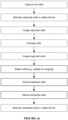
- a method 300 of captured particle retrieval preferably includes imaging captured particles (e.g., captured within a particle capture substrate 200), selecting captured particles, extracting the selected particles, and delivering the extracted particles (e.g., as shown in FIGURE 8 ).
- the particles are preferably cells (e.g., live cells), but can additionally or alternatively include any other suitable particles.
- the method 300 is preferably implemented using the system 100 (and/or particle capture platform) described above, but can additionally or alternatively be implemented using any other suitable mechanisms.
- the captured particles are preferably imaged by the imaging subsystem 120 (e.g., using bright-field microscopy, fluorescence microscopy, etc.). Particles are preferably selected (e.g., by the control subsystem 160, by a user, etc.) based on the imaging (e.g., selecting a particular type of cell, wherein the cell type is determined based on fluorescence microscopy).
- Particle extraction is preferably performed by the particle retriever subsystem 130, more preferably based on image data sampled by the imaging subsystem 120 (e.g., live video showing capture end 135 position relative to the selected cell), which can enable, for example, alignment of the particle extractor 134 over a target well and controlled insertion of the capture end 135 (e.g., into the target well; placement on top of the target well, such as with the capture end 135 in contact with the top surface of the walls defining the target well; etc.).
- image data sampled by the imaging subsystem 120 e.g., live video showing capture end 135 position relative to the selected cell
- the capture end 135 e.g., into the target well; placement on top of the target well, such as with the capture end 135 in contact with the top surface of the walls defining the target well; etc.
- Particle extraction is preferably performed by actuating the pump 132 (e.g., to reduce pressure within the particle extractor, thereby causing aspiration) while the capture end 135 is inserted (e.g., into the target well, on top of the target well, etc.).
- the particle extractor 134 is preferably repositioned at a target region (e.g., target well) of a particle receptacle 152, at which point particle delivery can be achieved by actuating the pump 132 (e.g., to increase pressure within the particle extractor, thereby expelling its contents).
- the control subsystem 160 preferably enables automated (and/or semi-automated) performance of the method 300 (and/or elements thereof).
- the control subsystem 160 can be configured to perform (e.g., based on image data received from the imaging subsystem 120): automated focusing (e.g., by moving the objective lens) on imaging targets such as wells, captured particles, and/or particle extractor capture ends (e.g., capillary tip); automated identification of target cells (e.g., based on fluorescence criteria); automated detection and lateral translation of the capture end (e.g., aligning the capture end with a target well that contains a target cell, aligning the capture end with a destination region of a particle receptacle, etc.); automated placement of the capture end in contact with (e.g., on top of, inserted into, etc.) the target well (e.g., avoiding crashes which can damage the capillary tip, rendering it inoperable to extract cells); automated pump actuation (e.g., to effect as
- Placing the capture end in contact with the target well can include, for example: focusing on a reference element of the capture substrate, preferably an element of the target well (e.g., top surface of the well); focusing on the particle extractor (e.g., on the capture end, such as the capillary tip); determining a relative distance between the reference element and the particle extractor (e.g., based on the objective lens motion required to switch focus between them); and moving the particle extractor based on the relative distance (e.g., moving toward the target well by an amount equal to the distance, moving by an amount less than the distance, etc.).
- a reference element of the capture substrate preferably an element of the target well (e.g., top surface of the well)
- the particle extractor e.g., on the capture end, such as the capillary tip
- determining a relative distance between the reference element and the particle extractor e.g., based on the objective lens motion required to switch focus between them
- focus can be adjusted (e.g., to follow the capture end movement, to switch back and forth between the reference element and the capture end, etc.) during and/or between capture end movement (e.g., repeatedly), and the relative distance determination can be updated accordingly.
- placing the capture end in contact with the target well can additionally or alternatively be performed using any other suitable techniques (e.g., insertion actuator force sensing and/or stalling).
- the system 100 can additionally or alternatively support methods (e.g., cell capture, imaging, and/or analysis methods) such as those described in U.S. Application Number 15/362,565, titled “System and Method for Capturing and Analyzing Cells” and filed 28-NOV-2016 , U.S. Application Number 14/208,298 titled “System and Method for Capturing and Analyzing Cells” and filed on 13-MAR-2014 , U.S. Application Number 15/074,054 titled titled “System and Method for Capturing and Analyzing Cells” and filed on 18-MAR-2016 , and/or U.S.
- methods e.g., cell capture, imaging, and/or analysis methods
- the method 300 can include capturing particles (e.g., capturing live cells in single-cell format) within wells of a particle capture substrate 200, prior to particle imaging, selection, extraction, and delivery (e.g., as shown in FIGURE 9 ).
- the method 300 can additionally or alternatively include any other suitable elements performed in any other suitable manner.
- the method 300 includes: capturing live cells (e.g., in single-cell and/or single-cluster format) in a particle capture substrate 200; maintaining the cells in a viable format (e.g., for multiple days, weeks, etc.); imaging the cells; processing the cells; re-imaging the cells after processing; selecting cells based on the imaging data (e.g., initial imaging and/or re-imaging); extracting the selected cells and delivering the extracted cells to a particle receptacle (e.g., using the system 100 as described above) such as a 96 well plate or a second particle capture substrate; maintaining and/or growing the cells (e.g., culturing the cells) for an extended time period (e.g., days, weeks, etc.); and/or imaging and/or monitoring the extracted cells (e.g., during culturing).
- a particle receptacle e.g., using the system 100 as described above
- a particle receptacle e.g., using the
- processing the cells includes treating all captured cells with a set of reagents (e.g., CRISPR reagents).
- processing the cells includes: selecting cells (e.g., a subset of the cells), such as based on the imaging data; and delivering reagents to the selected cells (e.g., the same set of reagents for each selected cell, different sets of reagents for different cells, etc.).
- the reagents can be delivered using the particle retriever subsystem (e.g., using the cell extractor; using a different reagent delivery element attached to the particle retriever subsystem, such as in place of the cell extractor; etc.) and/or any other suitable targeted delivery mechanism.
- the reagent can be delivered using a thinner capillary tube (e.g, thin enough to fit inside the target well, thin enough to penetrate the captured cell, etc.) attached to the particle retriever subsystem, and can optionally include inserting the capillary tube into the target well and/or the captured cell for reagent delivery (e.g., delivering CRISPR reagents directly into the cytosol of the target cell).
- a thinner capillary tube e.g., thin enough to fit inside the target well, thin enough to penetrate the captured cell, etc.
- the method 300 can additionally or alternatively include any other suitable elements.
- the system 100 and method 300 of the preferred embodiment and variations thereof can be embodied and/or implemented at least in part as a machine configured to receive a computer-readable medium storing computer-readable instructions.
- the instructions are preferably executed by computer-executable components preferably integrated with the system and one or more portions of a processor and/or a controller.
- the computer-readable medium can be stored on any suitable computer-readable media such as RAMs, ROMs, flash memory, EEPROMs, optical devices (CD or DVD), hard drives, floppy drives, or any suitable device.
- the computer-executable component is preferably a general or application specific processor, but any suitable dedicated hardware or hardware/firmware combination device can alternatively or additionally execute the instructions.
- each block in the flowchart or block diagrams may represent a module, segment, or portion of code, which comprises one or more executable instructions for implementing the specified logical function(s).
- the functions noted in the block can occur out of the order noted in the FIGURES. For example, two blocks shown in succession may, in fact, be executed substantially concurrently, or the blocks may sometimes be executed in the reverse order, depending upon the functionality involved.
Abstract
Description
- This application is a continuation-in-part of
U.S. Application number 15/657,553, filed 24-JUL-2017 U.S. Patent Application serial number 15/333,420, filed 25-OCT-2016 U.S. Patent Application serial number 14/607,918, filed 28-JAN-2015 U.S. Patent Application serial number 13/557,510, filed 25-JUL-2012 U.S. Provisional Application serial number 61/513,785 filed on 01-AUG-2011 - This application is also a continuation-in-part of
U.S. Application number 15/720,194, filed 29-SEP-2017 15/431,977, filed 14-FEB-2017 U.S. Application number 14/863,191 (nowU.S. Patent number 9,610,581), filed 23-SEP-2015 U.S. Application number 14/208,298 (nowU.S. Patent number 9,174,216), filed 13-MAR-2014 U.S. Provisional Application serial number 61/894,150, filed on 22-OCT-2013 U.S. Provisional Application serial number 61/829,528, filed on 31-MAY-2013 U.S. Provisional Application serial number 61/779,049, filed on 13-MAR-2013 - This application is also a continuation-in-part of
U.S. Application number 15/430,833, filed 13-FEB-2017 U.S. Patent Application serial number 15/199,245, filed 30-JUN-2016 U.S. Patent Application serial number 14/208,458, filed 13-MAR-2014 U.S. Provisional Application serial number 61/902,431, filed on 11-NOV-2013 U.S. Provisional Application serial number 61/779,090, filed on 13-MAR-2013 - This application claims the benefit of
U.S. Provisional Application serial number 62/423,322, filed 17-NOV-2016 U.S. Provisional Application serial number 62/545,251, filed 14-AUG-2017 - This application is also related to
U.S. Application number 15/442,222, filed 24-FEB-2017 - This invention relates generally to the particle analysis field, and more specifically to a new and useful system and method for retrieving and analyzing particles within the particle analysis field.
- With an increased interest in cell-specific drug testing, diagnosis, and other assays, systems that allow for individual cell isolation, identification, and retrieval are becoming more desirable within the field of cellular analysis. Furthermore, with the onset of personalized medicine, low-cost, high fidelity cellular analysis systems are becoming highly desirable. However, preexisting cell and other particle capture systems suffer from various shortcomings that prevent widespread adoption for cell-specific testing. For example, flow cytometry requires that the cell be simultaneously identified and sorted, and limits cell observation to the point at which the cell is sorted. Flow cytometry fails to allow for multiple analyses of the same cell within a single flow cytometry workflow, and does not permit arbitrary cell subpopulation sorting. Conventional microfluidic devices typically fail to allow for subsequent cell removal without cell damage, and only capture the cells expressing the specific antigen; nonexpressing cells, which could also be desired, are not captured by these systems. Such loss of cell viability can preclude live-cell assays from being performed on sorted or isolated cells. Cellular filters can separate sample components based on size without significant cell damage, but suffer from clogging and do not allow for specific cell identification, isolation of individual cells, and retrieval of identified individual cells. Other technologies in this field are further limited in their ability to allow multiplex assays to be performed on individual cells, while minimizing sample preparation steps and overly expensive instrumentation.
- Thus, there is a need in the particle sorting field to create new and useful systems and methods for retrieving and analyzing cells, and the inventions disclosed herein provide such useful systems and methods.
-
-
FIGURE 1A is a schematic representation of an embodiment of the system. -
FIGURE 1B is a schematic representation of an example of the system. -
FIGURE 2 depicts a first and second micrograph of cells extracted using the system. -
FIGURE 3A depicts specific examples of various aspects of the system. -
FIGURE 3B is a schematic representation of a variation of a method performed using the system. -
FIGURES 4A-4B are perspective views of a first specific example of the system, with and without a particle receptacle, respectively. -
FIGURE 5A is a first detail view of a region ofFIGURE 1B . -
FIGURE 5B is a plan view of a specific example of particle capture substrates and a particle receptacle arranged in the system. -
FIGURES 6A-6B are a second and third detail view, respectively, ofFIGURE 1B . -
FIGURE 7 is a perspective view of a second specific example of the system. -
FIGURE 8 is a flow chart representation of an embodiment of the method. -
FIGURE 9 is a schematic representation of a first example of the method. -
FIGURE 10 is a flow chart representation of a second example of the method. - The following description of the preferred embodiments of the invention is not intended to limit the invention to these preferred embodiments, but rather to enable any person skilled in the art to make and use this invention.
- As shown in
FIGURE 1A , asystem 100 for retrieving and analyzing a particle of a set of particles preferably includes: astructural frame 10 supporting: acapture stage 110 that positions aparticle capture substrate 200 in a capture mode of thesystem 100; animaging subsystem 120 operable to image the particle capture substrate 200 (e.g., wherein theimaging subsystem 120 includes an illumination subsystem 122 operable to transmit light toward thecapture stage 110 and cooperating with an optical sensor 126 operable to generate an image dataset of contents of theparticle capture substrate 200 in the capture mode); aparticle retriever subsystem 130 including apump 132 fluidly coupled to aparticle extractor 134; an actuation subsystem 140 including afirst unit 141 coupled the capture stage, asecond unit 142 coupled to the imaging subsystem, and athird unit 143 coupled to the particle retriever subsystem; aparticle receptacle station 150 hosting aparticle receptacle 152; and acontrol subsystem 160 that, based on a position of the particle at the capture substrate identified from the image dataset, generates commands to retrieve the particle and transmit the particle to theparticle receptacle 152. - In more detail (e.g., as shown in
FIGURES 1B and/or 7), an embodiment of thesystem 100 can include: astructural frame 10 supporting: acapture stage 110 defining a broad face 112 that positions aparticle capture substrate 200 having a set of particle capture chambers 210 oriented perpendicular to the broad surface 112 in a capture mode of thesystem 100, the broad surface 112 including an opening 114 toward a closed surface 220 of thecapture substrate 200 in the capture mode; animaging subsystem 120 including: an illumination subsystem 122 operable to transmit light toward the opening 114, a filter subsystem 124 operable to filter light transmitted between the illumination subsystem 122 and thecapture substrate 200 in the capture mode, and an optical sensor 126 cooperating with a focusing andoptics subsystem 128 that manipulates light transmitted to the optical sensor 126, the optical sensor 126 operable to generate an image dataset of contents of the set of particle capture chambers 210 in the capture mode; aparticle retriever subsystem 130 including apump 132 fluidly coupled to a particle extractor 134 (e.g., capillary tube) having acapture end 135 facing an open surface 230 of the capture substrate in the capture mode; an actuation subsystem 140 including afirst unit 141 coupled to the capture stage, asecond unit 142 coupled to the imaging subsystem, and athird unit 143 coupled to the particle retriever subsystem; aparticle receptacle station 150 hosting aparticle receptacle 152; and acontrol subsystem 160 that, based on a position of the particle at the capture substrate identified from the image dataset, generates commands for aligning theparticle extractor 134 with the position of the particle by the actuation subsystem, controlling pressure provided by the pump of the particle retriever subsystem, and transmitting the particle to the particle receptable, thereby retrieving the particle in single-particle format in the capture mode. - In some variations, the
system 100 can include: adisplay 170 in communication with thecontrol subsystem 160, the display operable to render at least one of: control parameters of the system associated with thecontrol subsystem 160 and images derived from the image dataset; and a containment subsystem 180 (e.g., sterile hood) operable to create a sterile environment for sample handling, thecontainment subsystem 180 configured about thestructural frame 10. - The system preferably functions to provide a portable, sterile environment for retrieval of individual cells (e.g., captured in single-cell format) and/or cell clusters. The system preferably enables automated cell localization and identification (e.g., based on image data, such as fluorescence microscopy data), cell extractor 134 (e.g., capillary tube) alignment and insertion, cell extraction (e.g., by aspiration), and/or extracted cell delivery (e.g., to a specified location of a cell receptacle such as a multi-well plate). However, the system can additionally or alternatively perform any other suitable functions.
- In a specific example, with a capillary having a 30µm inner diameter (or other suitable diameter), the system can achieve a throughput of over 90 particles retrieved in 90 minutes, transferring retrieved single cells in a viable state to downstream containers such as well plates (e.g., 96-well plates, well plates of any other suitable format), tubes (e.g., PCR tubes, conicals, etc.), dishes (e.g., Petri dishes), or any other suitable downstream container. As shown in
FIGURE 2 , cells (e.g., MCF7 cells) retrieved in single-cell format from the system can be retrieved in a viable state and grown in culture for further analysis. In the specific example, 5-color fluorescence and brightfield imaging subsystems of the system facilitate positioning of the capillary relative to a target particle/cell of interest for retrieval, in coordination with a computing system for image acquisition, control of illumination, and imaging focus. In the specific example, the system can be placed in a sterile hood for sterile operation; however, variations of the system can alternatively have any other suitable dimension(s) in relation to sterile sample processing. - The
structural frame 10 preferably functions to support the other elements of the system 100 (e.g., mechanically coupled to the other elements, such as statically coupled and/or coupled via one or more actuator and/or hinged). For example (e.g., as shown inFIGURE 1B ), thestructural frame 10 can include a member supporting some or all of the focusing and optics subsystem 128 (e.g., by way of asecond unit 142 of the actuation subsystem 140), a member supporting the remainder of theimaging subsystem 120, a member supporting the capture stage 110 (e.g., by way of afirst unit 141 of the actuation subsystem 140) and optionally theparticle receptacle station 150, and a member supporting the particle retriever subsystem 130 (e.g., by way of athird unit 143 of the actuation subsystem 140). - In some embodiments, the structural frame member supporting the
particle retriever subsystem 130 includes an arm extending between the actuation subsystemthird unit 143 and the particle retriever subsystem 130 (e.g., cantilevered from the third unit 143), which preferably retains the particle extractor substantially in alignment with the optical axis. The are is preferably configured to minimize undesired particle extractor motion (e.g., due to vibration), such as limiting such motion to less than a threshold deviation from the desired position (e.g., less than 10, 5, 2, 1, 0.5, 0.25, or 0.1 microns). For example, the arm can have a natural vibrational mode resulting in a vibrational amplitude of less than the threshold deviation, and/or the system can include one or more vibration dampers between the arm and the third unit 143 (e.g., thereby reducing particle extractor vibrational motion). However, undesired particle extractor motion can additionally or alternatively be minimized in any other suitable manner. - In some embodiments, the
structural frame 10 includes multiple independent frame modules (e.g., each supporting elements of distinct subsystems) configured to be attached (e.g., reversibly and/or repeatably attached) to each other, such as by mechanical fasteners (e.g., bolts, clips, clamps, etc.). For example (e.g., as shown inFIGURES 4A-4B ), thestructural frame 10 can include a first module that supports (e.g., houses, encloses, etc.) the imaging subsystem 120 (andsecond unit 142 of the actuation subsystem 140) and a second module that supports the capture stage,particle retriever subsystem 130, and remaining elements of the actuation subsystem 140 (e.g., wherein the second module has dimensions between 10 and 50 cm on each side, such as 33 × 41 × 25 cm). - The
structural frame 10 preferably includes (e.g., is made of) one or more rigid materials, such as metal and/or a rigid polymer. Thestructural frame 10 can optionally enclose (or substantially enclose) all of some of the other elements of the system (e.g., thereby providing mechanical protection for the elements and/or otherwise isolating the elements from their surroundings). For example, thestructural frame 10 can form an optical enclosure (e.g., opaque enclosure, such as a full or partial light-tight enclosure) around some or all of the imaging subsystem 120 (e.g., reducing background readings from ambient light). However, thestructural frame 10 can additionally or alternatively include any other suitable elements in any other suitable configuration. - The
capture stage 110 preferably functions to receive and align one or more particle capture substrates 200 (e.g., cell capture devices) relative to the imaging subsystem 120 (e.g., theillumination module 110, focusing andoptics subsystem 128, optical sensor 126, etc.), the particle retriever subsystem 130 (e.g., the cell extractor 134), and/or any other suitable elements of the system 100 (e.g., as shown inFIGURES 5A, 5B , and6A ). Such alignment can enable light-based analyses and/or opticallyguided retrieval of captured cells (and/or other particles) of interest within theparticle capture substrate 200. - The
capture stage 110 preferably defines a broad face 112 coupled to (e.g., retaining, supporting, etc.) one or moreparticle capture substrates 200. For example, thecapture stage 110 can support a plurality of particle capture substrates 200 (e.g., a closed surface 220 of eachsubstrate 200 retained against the broad face 112 by gravity, by one or more fasteners such as spring clips and/or screws pressing upon an open surface 230 of eachsubstrate 200, etc.). Thecapture stage 110 preferably positions theparticle capture substrate 200 such that a broad face of the substrate (e.g., the closed surface 220) is against (e.g., substantially coplanar with) the broad face 112 (e.g., in a capture mode). For example, thesubstrate 200 can be positioned such that a set of particle capture chambers 210 (e.g., defined in the open surface 230, such as normal the open surface 230 and/or closed surface 220) are oriented perpendicular to the broad surface 112. Thecapture stage 110 preferably does not impede access to the open surface 230 (e.g., to the chambers 210), but can additionally or alternatively include any suitable elements arranged on and/or near the open surface 230. - The broad face 112 preferably includes one or more openings 114. Each opening 114 can provide optical access (e.g., allow light transmission, enable close proximity of an objective lens, etc.) to the closed surface 220 of a
substrate 200. Each opening 114 can be a void defined in the broad face 112, a window of transparent material, and/or can be any other suitable opening 114. - The
capture stage 110 can additionally or alternatively support the particle receptacle station 150 (e.g., adjacent the particle capture substrates 200). In one example, thecapture stage 110 rigidly couples theparticle capture substrates 200 and theparticle receptacle station 150, enabling coordinated movement of thecapture stage 110 and all the rigidly coupled elements (e.g., by thefirst unit 141 of the actuation subsystem 140). However, thecapture stage 110 can additionally or alternatively support any other suitable elements of the system in any other suitable manner. - The
capture stage 110 can optionally include elements as described inU.S. Application number 15/430,833, filed 13-FEB-2017 capture stage 110 can additionally or alternatively include any other suitable elements in any suitable arrangement. - The
imaging subsystem 120 preferably includes: an illumination subsystem 122 (e.g., operable to transmit light toward the opening 114), a filter subsystem 124 (e.g., operable to filter light transmitted between the illumination subsystem 122 and thecapture substrate 200 in the capture mode), and an optical sensor 126 cooperating with a focusing and optics subsystem 128 that manipulates light transmitted to the optical sensor 126 (e.g., the optical sensor 126 operable to generate an image dataset of contents of the set of particle capture chambers 210 in the capture mode), such as shown inFIGURE 6B . Theimaging subsystem 120 can include elements such as those described inU.S. Application number 15/430,833, filed 13-FEB-2017 - The
imaging subsystem 120 preferably includes a microscope (e.g., inverted microscope) such as a fluorescence microscope. In one example, the illumination subsystem 122 includes a bright-field illumination source (e.g., white light source such as one or more white LEDs, narrow-spectrum and/or single wavelength light source, etc.) and/or a fluorescence light source (e.g., wide-spectrum light source, preferably including ultraviolet and/or infrared wavelengths of light), preferably with adjustable intensity; the filter subsystem 124 includes one or more excitation filters, emission filters, and/or dichroic mirrors (e.g., grouped into one or more filter modules, such as aligned groups including a single excitation filter, dichroic mirror, and emission filter); the optical sensor 126 includes a photodiode comprising a photoelectric material configured to convert electromagnetic energy into electrical signals; and the focusing and optics subsystem 128 includes a lens (e.g., objective lens) configured to focus light from the illumination module onto a target object (e.g.,particle capture substrate 200, captured cell, capture end 135 of thecell extractor 134, etc.) at the capture stage 110 (and/or a lens configured to focus light from the target object onto the optical sensor). The lens is preferably oriented substantially normal the broad face 112 (e.g., defines an optical axis substantially normal the broad face 112). The lens (and/or other elements of the focusing and optics subsystem 128) is preferably configured to be moved (e.g., translated substantially along the optical axis) by thesecond unit 142 of the actuation subsystem 140. However, theimaging subsystem 120 can additionally or alternatively include any other suitable elements in any other suitable arrangement. - The
particle retriever subsystem 130 preferably functions to extract at least one of a single cell and a cell cluster (and/or any other suitable particles) from a well of the array. While an individual cell from a single well is preferably selectively removed, theparticle retriever subsystem 130 can facilitate simultaneous multiple cell/cell cluster removal from the set of wells. The cell/cell cluster is preferably removed by applying a removal force to the cell. The removal force can be applied by capillary force, but can additionally or alternatively be applied by aspirating the contents out of a well (i.e., using a negative pressure). The removal force can additionally or alternatively be applied by pumping fluid through the set of wells (e.g., by way of a perimeter channel) to provide a positive pressure that drives the cell/cell cluster from the well. In one variation, the pump pressure provided by a pump mechanism at theparticle retriever subsystem 130 is less than 10,000Pa, and in a specific variation, the provided pump pressure is 6,000Pa. However, any other suitable pump or aspiration pressure can be used. - In some variations, the
particle retriever subsystem 130 can comprise acell extractor 134. Thecell extractor 134 functions to selectively remove one or more isolated cells from an addressable location within thesystem 100. Thecell extractor 134 is preferably configured to remove a cell/cell cluster from a single well, but can alternatively be configured to simultaneously remove multiple cells/cell clusters from multiple wells. Theparticle retriever subsystem 130 is preferably operable in an extraction mode, wherein in the extraction mode theparticle retriever subsystem 130 extracts at least one of a set of single cells from a well of the set of wells, along a direction normal to the base surface of the well. In the extraction mode, the fluid delivery module is preferably removed from the substrate; however, the fluid delivery module can alternatively remain coupled to the substrate when the cell removal module is operated in the extraction mode. - In a first variation of the
cell extractor 134, thecell extractor 134 is configured to access the set of wells from a direction normal to the open surface 220 (e.g., broad surface) of thesubstrate 200. Thecell extractor 134 preferably removes the cell/cell cluster in a substantially normal direction from the open surface 220 of thesubstrate 200, but can alternatively remove the cell/cell cluster in an angled direction relative to the open surface 220. Thecell extractor 134 preferably defines an interior void, such as a hollow channel (e.g., of a micropipette, capillary tube such as a glass capillary tube, etc.), between acapture end 135 and an outlet (e.g., opposing thecapture end 135 across the length of the cell extractor 134) that accesses the set of wells and defines a substantially fluidly isolated volume in fluid communication with one or more wells. The void can include one or more sealing elements at the capture end 135 (e.g., a polymeric coating or adequate geometry) that facilitate fluid seal formation with the well(s) 113. Theparticle retriever subsystem 130 can optionally include a protective member (e.g., polymer sheath) surrounding a portion of the cell extractor 134 (e.g., surrounding most of an exposed length of theextractor 134, wherein the extractor tip emerges from the sheath to avoid sheath interference with thesubstrate 200 during tip insertion). Thecell extractor 134 preferably tapers from a proximal end to the capture end 135 (e.g., tip), in order to provide an adequate geometry to receive contents of a well into thecell extractor 134; however, thecell extractor 134 can alternatively have any other suitable form. As such, the hollow needle is preferably configured to form a substantially fluidly isolated volume within a well of interest, and a low-pressure generator (e.g., a pump) is then used to aspirate the retained cell/cell cluster out of the well, through the hollow channel, and into a cell collection volume of thecell extractor 134. The void preferably defines a micron-scale aperture at thecapture end 135, such as an aperture having a characteristic dimension (e.g., diameter, width, inscribed and/or circumscribed circle diameter, etc.) between 1 micron and 500 microns (e.g., between 10 and 100 microns, between 20 and 50 microns, 30 microns, 40 microns, etc.). In one variation, thecell extractor 134 is a micropipette having a height of 200 micrometers and a hollow channel diameter of 25 micrometers; in another variation, thecell extractor 134 is a capillary tube having a channel diameter of 30 micrometers; in a third variation, thecell extractor 134 is a capillary tube having a channel diameter of 150 micrometers. In another variation, the wells of the set of wells are grouped such that each group may be circumscribed by a closed curve in the plane parallel to the broad surface of the substrate, and thecell extractor 134 has an inner diameter that is smaller than the largest chord of the closed curve. In another variation, the inner diameter is smaller than a characteristic dimension (e.g., width, diameter, etc.) of a single well. However, other variations of these specific examples can have any other suitable defining dimensions. - The
cell extractor 134 can enable aspiration and/or dispensal of a samples (e.g., particles such as cells, surrounding liquid, etc.) up to a maximum volume (e.g., equal to or less than the volume of the void or a fillable portion thereof). The maximum volume can be a volume between 0.1 and 500 microliters (e.g., between 1 and 50 microliters, such as 5, 10, or 25 microliters). However, thecell extractor 134 can additionally or alternatively accommodate any other suitable sample volume. - The
cell extractor 134 can be manufactured using microfabrication techniques, or can additionally or alternatively be injection molded, laser cut, stamped, or manufactured using any other suitable manufacturing technique. In one variation of hollow needle manufacture, a lumen is preferably etched into a substrate, such as silicon, using etching techniques such as deep reactive ion etching (DRIE), plasma etching, or any other suitable etching method. This step is preferably utilized with a mask that covers the portions of the substrate 105 to be protected. The walls and associated profiles are then preferably manufactured through isotropic etching of the substrate 105 utilizing a corrosive liquid or plasma, but any other suitable isotropic material removal method can be used. A mask is preferably used to protect the puncture end. In a second variation, tubes (e.g., glass tubes, plastic tubes, etc.) can be pulled (e.g., by applying controlled heating to the tube end and pulling the tube under controlled tension) to narrow the tube opening to the desired diameter. Multiple hollow needles are preferably simultaneously manufactured as anarray 200, but can alternatively be individually manufactured. - The
particle retriever subsystem 130 preferably includes apump 132 configured to alter pressure within the cell extractor void (e.g., within the hollow channel of the capillary tube). Thepump 132 is preferably a positive displacement pump, more preferably a syringe pump, but can additionally or alternatively include any other suitable pump(s). For example, thepump 132 can include a piezoelectric actuator, a diaphragm pump, and/or any other suitable pumping mechanisms. - The
pump 132 is preferably controlled by apump actuator 144, more preferably a motorized actuator (e.g., configured to be controlled by they control subsystem 160), such as described below regarding the actuation subsystem 140. However, thepump 132 can additionally or alternatively be controlled directly (e.g., by manual translation of the syringe pump plunger within the syringe pump barrel, such as by pushing or pulling directly on the plunger by hand). - The pump 132 (e.g., a fluid port of the pump, such as an inlet or outlet) is preferably fluidly coupled to the cell extractor 134 (e.g., to the void) by a
tube 136, more preferably a flexible tube. A flexible tube can enable independent movement of thecell extractor 134 with respect to the pump 132 (e.g., during actuation of the actuation subsystemthird unit 143; such as during alignment, insertion, and/or removal of the capture end 135). Thetube 136 preferably includes (e.g., is made of) a polymeric material (e.g., Teflon, Tygon, polyethylene, etc.), but can additionally or alternatively include metal (e.g., steel, copper, etc.) and/or any other suitable materials. To create effective pumping pressure (e.g., for cell extraction), the dead-volume of thetube 136 is preferably minimized, such as a dead-volume less than a threshold maximum volume (e.g., less than 25, 15, 10, 5, 2, 1, or 0.5 microliters). In one example, the dead-volume is reduced by placing a a filler element, such as a wire, inside the tube (e.g., 400 micron diameter wire placed within a tube with a 500 micron inner diameter), thereby occupying a portion of the tubing volume. Thetube 136 is preferably a single tube running between thepump 132 andcell extractor 134, but can additionally or alternatively include any suitable fluid manifold and/or other fluidic coupling. - The
particle retriever subsystem 130 preferably enables easy removal and/or attachment (e.g., reattachment) of the cell extractor 134 (e.g., capillary tube). This can enable cell extractor cleaning and/or replacement (e.g., of contaminated and/or damaged cell extractors). For example, thecell extractor 134 can be coupled to thetube 136 by a friction fitting (e.g., optionally including hose barbs defined on thecell extractor 134 and/or hose clamps retaining thetube 136 in place on the cell extractor 134). Theparticle retriever subsystem 130 can include a number of disposable (e.g., onetime use)cell extractors 134, and/or can include one ormore cell extractors 134 configured for reuse. However, theparticle retriever subsystem 130 can include any other suitable set ofcell extractors 134 of any suitable type(s), and/or can include only a single cell extractor 134 (e.g., non-removeable cell extractor). - The
particle retriever subsystem 130 can, however, include any other suitable cell removal tool, such as that described inU.S. Application No. 13/557,510, entitled "Cell Capture System and Method of Use" and filed on 25-JUL-2012 - Cell removal from the
system 100 is preferably automated, but can additionally or alternatively be semi-automated or manual. Furthermore, cell removal can be performed along with cell identification, comprising automatic fixing, permeabilization, staining, imaging, and identification of the cells removed from the set of wells through image analysis (e.g., through visual processing with a processor, by using a light detector, etc.) or in any other suitable manner. Theparticle retriever subsystem 130 can be configured to facilitate advancement of acell extractor 134 to a well containing a cell/cell cluster of interest, for instance, with an actuation subsystem. Theparticle retriever subsystem 130 can additionally or alternatively be configured to facilitate cell removal method selection and/or cell removal tool selection. In another variation, cell identification at theparticle retriever subsystem 130 can be semi-automated, and cell retrieval can be automated. For example, cell staining and imaging can be done automatically, wherein identification and selection of the cells of interest can be done manually. In another variation, all steps can be performed manually. However, any combination of automated or manual steps can be used. - The actuation subsystem 140 preferably includes a
first unit 141 coupled to (e.g., controlling motion of) thecapture stage 110, asecond unit 142 coupled to (e.g., controlling motion of) theimaging subsystem 120, athird unit 143 coupled to (e.g., controlling motion of) theparticle retriever subsystem 130, and apump actuator 143 coupled to (e.g., controlling pumping action of) thepump 132. - The
first unit 141 preferably enables and/or controls lateral motion (e.g., translation along one or more axes substantially parallel the broad face 112) of thecapture stage 110 and/orparticle receptacle station 150. For example, thefirst unit 141 can include an X-axis translator (e.g., controlling lateral translation along a long edge of the capture stage 110) and a Y-axis translator (e.g., controlling lateral translation along an axis perpendicular to the X-axis). Thefirst unit 141 can additionally or alternatively enable and/or control translation along an out-of-plane axis (e.g., Z-axis substantially perpendicular the X- and Y-axes, axis substantially normal the broad face 112, axis substantially parallel the optical axis, vertical axis, etc.), lateral rotation (e.g., about the out-of-plane axis), tilt (e.g., rotation about one or more axes substantially parallel the broad face 112, such as the X- and/or Y-axis), and/or any other suitable motion. - The
first unit 141 can optionally include an actuator for moving thecapture stage 110 and/orparticle receptacle station 150 between a particle extraction configuration (e.g., in which theparticle capture substrate 200 is aligned with theparticle extractor 134 and/or optical axis) and a particle delivery configuration (e.g., in which theparticle receptacle station 150 is aligned with theparticle extractor 134 and/or optical axis). For example, thecapture stage 110 and particle receptacle station 150 (and optionally, other actuators of the first unit 141) can translate along a track and/or rotate about a joint axis (e.g., vertical axis, horizontal axis, etc.) of a cantilever arm to switch between the particle extraction and particle delivery configurations. However, thefirst unit 141 can additionally or alternatively include any other suitable elements in any other suitable configuration. - The
second unit 142 preferably includes a focus actuator enabling and/or controllingimaging subsystem 120 focusing (e.g., by moving the objective lens closer to and/or farther from the imaging target, such as theparticle capture substrate 200, its contents, and/or thecapture end 135 of the particle extractor). For example, the focus actuator can enable and/or control translation of the objective lens (and/or other optical elements) along the optical axis and/or an axis substantially normal the broad face 112. The focus actuator preferably enables precise control of objective lens movement along the optical axis, such as enabling control to less than a threshold precision (e.g., 10, 50, 75, 100, 150, 400, or 1000 nm). Thesecond unit 142 can optionally include optical element selection actuators, such as rotational and/or translational actuators that move optical elements (e.g., objective lenses, filters, etc.) into and/or out of the optical path. Thesecond unit 142 can additionally or alternatively include lateral translation actuators (e.g., enabling and/or controlling translation of imaging subsystem elements along axes substantially parallel the broad face 112 and/or perpendicular the optical axis), tilt actuators (e.g., enabling and/or controlling rotation of imaging subsystem elements, such as about axes substantially parallel the broad face 112 and/or normal the optical axis), and/or any other suitable actuators. - The
third unit 143 preferably includes one or more actuators (e.g., insertion actuator) that enable and/or control out-of-plane motion (e.g., translation along one or more out-of-plane axes not substantially parallel the broad face 112) of the particle extractor 134 (e.g., relative to thecapture stage 110 and/or particle receptacle station 150). The out-of-plane axis is preferably an axis substantially normal the broad face 112 and/or the well apertures. However, the out-of-plane axes can additionally or alternatively include a vertical axis, an axis substantially parallel an axis defined by the particle extractor 134 (e.g., defined by the void, such as a central axis of the capillary tube), an axis substantially parallel the optical axis, and/or any other suitable axes. For example, the insertion actuator can control insertion (and/or removal) of thecapture end 135 into the substrate 200 (e.g., into the target well; on top of the target well, such as with thecapture end 135 in contact with the top surface of the well; etc.), thereby enabling extraction of the well contents (e.g., cell and/or cell cluster, such as a cell captured in single-cell format). The insertion actuator preferably enables precise control of particle extractor motion along the out-of-plane axis (e.g., optical axis), such as enabling control to less than a threshold precision (e.g., 10, 50, 75, 100, 150, 400, or 1000 nm). The insertion actuator can additionally or alternatively be configured to use force sensing and/or stalling of the actuator motor (e.g., to allow precise positioning of thecapture end 135 on top of a nanowell). - The
third unit 143 can additionally or alternatively include one or more lateral translation actuators. The lateral translation actuators preferably enable and/orcontrol extractor 134 translation along one or more axes substantially parallel the broad face 112 (e.g., the X- and Y-axes) and/or substantially perpendicular the out-of-plane actuator axis. The lateral translation actuators can enable lateral alignment of theparticle extractor 134, such as alignment with the optical axis, the target well, aparticle receptacle 152 and/or portion thereof (e.g., target well of a multi-well plate), and/or any other suitable element of the system. Thethird unit 143 can optionally include one or more tilt actuators, which can enable and/or control rotation of theextractor 134 about one or more axes (e.g., lateral axes such as axes substantially parallel the X- and Y-axes). The tilt actuators can enable angular alignment of theparticle extractor 134, can enable extraction of particles from wells with different orientations (e.g., including orientations requiring insertion at oblique angles to the broad face 112), and/or can perform any other suitable function. - The
third unit 143 can additionally or alternatively include an actuator (e.g., analogous to the actuator described above regarding the first unit 141) for moving theextractor 134 between the particle extraction configuration (e.g., in which theparticle extractor 134 is aligned with theparticle capture substrate 200 and/or optical axis) and a particle delivery configuration (e.g., in which theparticle extractor 134 is aligned with the particle receptacle station 150). For example, the extractor 134 (and optionally, other actuators of thethird unit 143, thepump 132 and/orpump actuator 144, and/or any other suitable elements of the system) can translate along a track and/or rotate about a joint axis (e.g., vertical axis, horizontal axis, etc.) of a cantilever arm to switch between the particle extraction and particle delivery configurations. However, thethird unit 143 can additionally or alternatively include any other suitable elements in any other suitable configuration. - The actuators of the
third unit 143 preferably control motion of theparticle extractor 134 but not of the pump 132 (e.g., wherein theextractor 134 is mechanically coupled to thepump 132 by the actuators). However, all or some of the actuators of thethird unit 143 can optionally control motion of the pump 132 (e.g., moving thepump 132 andextractor 134 together). - The
pump actuator 144 preferably functions to control pumping action (e.g., pressure differential, pumped volume, etc.) of thepump 132. Thepump actuator 144 can be used to control aspiration and/or delivery of cell extractor contents (e.g., thereby enabling extraction of particles, such as cells, from thesubstrate 200 and/or delivery of the extracted particles to the particle receptacle 152). In one example, theparticle retriever subsystem 130 can include a linear actuator coupled to the plunger of the syringe pump and configured to translate the plunger within the barrel of the syringe pump (e.g, substantially along a central axis defined by the barrel). The pump actuator 144 (e.g., plunger linear actuator) is preferably controlled by a motor, but can additionally or alternatively be manually actuated (e.g., by a knob) and/or controlled in any other suitable manner. In a second example, thepump actuator 144 includes a piezoelectric actuator (e.g., configured to perform pumping, such as by altering an internal volume of a positive displacement pump) configured to be controlled by electrical control signals (e.g., from the control subsystem 160). However, the actuation subsystem 140 can include any othersuitable pump actuators 144 of any other suitable type, which can be controlled (e.g., manually, automatically, such as by thecontrol subsystem 160, etc.) in any suitable manner. - All or some of the actuators preferably enable precise (e.g., sub-micron) control of system element movement. For example, the actuators can include micrometer heads and/or precision drives for precise manual and/or motorized motion control. However, the actuators can additionally or alternatively include any other suitable actuators with any suitable precision. All or some of the actuators can optionally include position detectors such as encoders (e.g., optical, magnetic, etc.; linear, rotary, etc.; absolute, relative, etc.), limit switches, and/or any other suitable position detectors. The position detectors are preferably configured to sample position data and to communicate the position data to other elements of the system (e.g., to the
control subsystem 160, to servomotors, etc.). All or some of the actuators can include motors (e.g., stepper motors, servomotors, etc.) and/or any other suitable mechanisms to enable automated control of the actuators (e.g., by the control subsystem 160). - In some variations, the actuation subsystem 140 (e.g., enabling control of capture stage movement, imaging subsystem movement, particle retriever subsystem movement, and/or movement of any other suitable elements of the system) includes elements (and/or enables control) such as described in
U.S. Application number 15/430,833, filed 13-FEB-2017 first unit 141 can include actuators such as described regarding the platform, thesecond unit 142 can include actuators such as described regarding the focusing and optics module, and thethird unit 143 and/orpump actuator 144 can include actuators analogous to those described regarding the actuators of the platform and/or focusing and optics module. However, the actuation subsystem 140 can additionally or alternatively include any other suitable actuators. - In some variations, all or some actuators of the actuation subsystem 140 can be configured to be controlled (e.g., be automatically controlled) by the
control subsystem 160. For example, thecontrol subsystem 160 can automatically control the first unit 141 (e.g., in order to facilitate automated functions including autofocusing of objects of interest, self-calibration, captured cell and/or particle receptacle alignment with theparticle extractor 134, cell capture device interrogation, cell capture device agitation, etc.), second unit 142 (e.g., in order to facilitate automated functions including autofocusing of objects of interest, self-calibration, magnification selection, filter selection, field of view selection, etc.), third unit 143 (e.g., in order to facilitate automated functions including captured cell and/or particle receptacle alignment with theparticle extractor 134, particle extractor insertion and/or withdrawal, etc.), pump actuator 144 (e.g., in order to facilitate automated functions including aspiration and/or delivery of fluid within theparticle extractor 134, particle extractor priming and/or cleaning, etc.), and/or any other suitable elements of the actuation subsystem 140. However, all or some actuators can additionally or alternatively be semi-automatically controlled and/or manually controlled, such that a user or other entity can manipulate thecapture stage 110 in some manner (e.g., using knobs, dials, and/or micrometer heads mechanically coupled to the capture stage 110). - The
particle receptacle station 150 preferably functions to receive and retain one ormore particle receptacles 152, and can optionally align theparticle receptacles 152 relative to the the particle retriever subsystem 130 (e.g., the cell extractor 134),capture stage 110, imaging subsystem 120 (e.g., theillumination module 110, focusing and optics subsystem 128, optical sensor 126, etc.), and/or any other suitable elements of thesystem 100. For example, theparticle receptacle station 150 can support one or more particle receptacles 152 (e.g., retained against thestation 150 by gravity and/or by one or more fasteners such as spring clips and/or screws pressing upon eachreceptacle 152; retained within thestation 150 by an inward force exerted along sidewalls of thereceptacle 152, such as a compressive force from a friction fit within a rubberized receptacle and/or any other suitable element of thestation 150; etc.). Theparticle receptacles 152 can include tubes (e.g., conical tubes, standard PCR tubes, etc.), multi-well plates (e.g., 96 well plates), Petri dishes, and/or any other suitable receptacles (e.g., receptacles configured to receive and/or contain cells and/or other particles). However, theparticle receptacle station 150 can additionally or alternatively include any other suitable elements in any other suitable arrangement. - The
particle receptacle station 150 can be rigidly coupled to the capture stage 110 (e.g., as described above), rigidly coupled to thestructural frame 10, actuatably coupled (e.g., by one or more actuators of the actuation subsystem 140, such as by the actuators of the first, second, and/or third units, and/or by other actuators enabling independent motion of the particle receptacle station 150) to thestructural frame 10 and/or any other suitable element of the system, and/or can be arranged within the system in any other suitable manner. - The
control subsystem 160 preferably functions to control system operation, such as enabling implementation (e.g., automated and/or semi-automated execution) of themethods 300 described below. - The
control subsystem 160 can include one or more: processors (e.g., CPU, GPU, microprocessor, etc.), memory and/or data storage modules (e.g., Flash, RAM, hard disk drive, etc.), and/or any other suitable components. The processing system is preferably mounted to thestructural frame 10, but can alternatively be mounted to any other suitable component, and/or can be mechanically separate from the other elements of the system 100 (e.g., can be connected to the system by a data connector, can communicate wirelessly with other components of the system, etc.). - The
control subsystem 160 is preferably configured to communicate with and/or control other system elements, such as theimaging subsystem 120 and/or actuation subsystem 140. For example, thecontrol subsystem 160 can be coupled (e.g., electrically coupled; otherwise coupled by a coupling capable of transmitting power, control signals, and/or data; etc.) to the optical sensor 126 (enabling activation of the optical sensor 126 and/or receipt of data, such as image data, from the optical sensor 126) and to one or more actuators of the actuation subsystem 140 (e.g., enabling control of the actuators and/or receipt of data, such as position data, from the actuation subsystem 140 position sensors). However, thecontrol subsystem 160 can additionally or alternatively include any other suitable components, be connected to any other suitable elements of the system, and/or perform any other suitable functions. - The
system 100 can optionally include adisplay 170. Thedisplay 170 is preferably configured to communicate with the control subsystem 160 (e.g., coupled to thecontrol subsystem 160 by a data connection, such as a video data cable; configured to wirelessly receive information from thecontrol subsystem 160; etc.). Thedisplay 170 is preferably configured to display one or more of: control parameters of the system associated with thecontrol subsystem 160 and images derived from the image dataset. For example, the display can show images (e.g., near-real time image streams, such as live videos; previously captured images; etc.) captured by theimaging subsystem 120 and/or derivatives thereof, control parameters and/or other information related to system operation (e.g., presented as overlays on the images, presented separate from and/or in place of images, etc.), and/or any other suitable information. The control parameters (e.g., information) presented on the screen (e.g., presented in overlays) can include: positions of system elements (e.g., coordinates, visual indications within and/or outside the image field of view, etc.); current and/or planned motion of system elements; cell identifications such as selected/non-selected cells, cell types (e.g., determined based on fluorescence microscopy data), etc.; target wells for cell retrieval (e.g., from wells of the substrate 200) and/or reception (e.g., at wells of the receptacle 152); retrieval process steps and/or status (e.g., "calibrating", "priming", "identifying cells", "retrieving cell 21 of 40", "washing capillary tube", etc.); and/or any other suitable information. However, thedisplay 170 can additionally or alternatively perform any other suitable function. - The
containment subsystem 180 preferably functions to create a sterile environment for sample handling (e.g., isolating the system contents, such as the contents of thesubstrate 200 and/orreceptacle 152, from an ambient environment surrounding the containment subsystem 180). In a first embodiment, thecontainment subsystem 180 is a sterile hood (e.g., biological safety cabinet), wherein the other elements of the system 100 (e.g., thestructural frame 10 and attached subsystems) fit within the sterile hood. In this embodiment, thestructural frame 10 preferably has dimensions sufficiently small to enable facile placement in (and optionally, removal from) a biological safety cabinet (e.g., less than 10 inches tall × 24 inches wide × 30 inches deep), but can alternatively have any other suitable dimensions. In a second embodiment, thecontainment subsystem 180 envelopes thestructural frame 10 and attached components (e.g., is attached directly to the exterior of thestructural frame 10. In one example (e.g., as shown in FIGURE XX), thecontainment subsystem 180 includes a hinged cover operable between a closed configuration, in which some or all elements of the system (e.g., thecapture stage 110 and particle retriever subsystem 130) are enclosed by the cover, and an open configuration which enables user access to the otherwise-enclosed components (e.g., to enable placement and/or removal of system elements, such asparticle capture substrates 200,particle extractors 134, etc.). However, thecontainment subsystem 180 can additionally or alternatively include any other suitable components in any suitable arrangement. - The
particle capture substrate 200 preferably defines a closed surface 220 (e.g., bottom surface) and an open surface 230 (e.g., top surface). The surfaces are preferably broad faces opposing each other (e.g., substantially parallel each other) across the substrate body. The open surface 230 preferably defines a plane, such as a substrate top plane. Thesubstrate 200 preferably defines a set of wells within the substrate body, each well of the set defining: an aperture (e.g., at the plane); a base arranged within the substrate body (e.g., between the aperture and the closed surface 220); and a wall extending from the aperture to the base. Further, thesubstrate 200 can define a plurality of channels within the substrate body, wherein some or all of the wells are fluidly coupled to one or more adjacent wells one or more of the channels. During cell extractor aspiration at a target well (e.g., during extraction of a cell captured in the target well), these channels can facilitate fluid flow (e.g., convective currents) from adjacent wells, through the target well, and into the cell extractor. This fluid flow can enable, facilitate, and/or urge the captured cell into the cell extractor. In a specific example, theparticle capture substrate 200 defines a hexagonal array (e.g., close-packed array) of hexagonal wells with micron-scale width (e.g., 1-100 microns, such as 1, 5, 10, 15, 20, 25, 30, 35, 40, 50, or 60 microns). In this specific example, the wells are subdivided into hexagonal groups of seven wells, wherein the wells of each hexagonal group are fluidly connected by channels, and the inter-group walls separating adjacent hexagonal groups do not allow fluid communication between the hexagonal groups (e.g., do not define channels). - Embodiments, variations, and examples of the
particle capture substrate 200 are described inU.S. Application Number 13/557,510 titled "Cell Capture System and Method of Use" and filed on 25-JUL-2012 U.S. Application Number 14/289,155 titled "System and Method for Isolating and Analyzing Cells" and filed on 28-MAY-2014 U.S. Application Number 15/422,222 titled "System and Method for Isolating and Analyzing Cells" and filed on 24-FEB-2017 particle capture substrate 200 can additionally or alternatively include any other suitable elements in any suitable arrangement. - As shown in
FIGURES 3A and 3B , thesystem 100 can optionally function within (and/or complementary to) a platform for capturing particles from a sample in single-particle format, wherein the platform includes a sample preparation portion operable to process a sample containing a set of particles of interest, and to transmit the processed sample through a particle capture substrate 200 (e.g. microfluidic chip, cell capture substrate, etc.) for capturing the set of particles in single-particle format (and/or in particle clusters). The particles (e.g., cells) can then be retrieved in single-cell format in a viable state for further processing and/or analysis (e.g., in relation to diagnostic applications). In a first embodiment, thesystem 100 and particle capture platform are integrated (e.g., share a common stage for retaining the particle capture substrate 200), wherein theparticle capture substrate 200 remains in place in the particle capture platform during both processed sample transmission and subsequent particle retrieval. In a second embodiment, following processed sample transmission, theparticle capture substrate 200 can be removed from the particle capture platform and placed in thecapture stage 110 for particle retrieval. However, thesystem 100 and particle capture platform can additionally or alternatively have any other suitable relationship. - Embodiments, variations, and examples of the sample preparation portion are described in
U.S. Application Number 14/208,298 titled "System and Method for Capturing and Analyzing Cells" and filed on 13-MAR-2014 U.S. Application Number 15/074,054 titled titled "System and Method for Capturing and Analyzing Cells" and filed on 18-MAR-2016 , andU.S. Application Number 14/208,458 titled "System for Imaging Captured Cells" and filed on 13-MAR-2014 system 100 can additionally or alternatively cooperate with any other suitable platform or platform components. - A
method 300 of captured particle retrieval preferably includes imaging captured particles (e.g., captured within a particle capture substrate 200), selecting captured particles, extracting the selected particles, and delivering the extracted particles (e.g., as shown inFIGURE 8 ). The particles are preferably cells (e.g., live cells), but can additionally or alternatively include any other suitable particles. Themethod 300 is preferably implemented using the system 100 (and/or particle capture platform) described above, but can additionally or alternatively be implemented using any other suitable mechanisms. - The captured particles are preferably imaged by the imaging subsystem 120 (e.g., using bright-field microscopy, fluorescence microscopy, etc.). Particles are preferably selected (e.g., by the
control subsystem 160, by a user, etc.) based on the imaging (e.g., selecting a particular type of cell, wherein the cell type is determined based on fluorescence microscopy). Particle extraction is preferably performed by theparticle retriever subsystem 130, more preferably based on image data sampled by the imaging subsystem 120 (e.g., live video showingcapture end 135 position relative to the selected cell), which can enable, for example, alignment of theparticle extractor 134 over a target well and controlled insertion of the capture end 135 (e.g., into the target well; placement on top of the target well, such as with thecapture end 135 in contact with the top surface of the walls defining the target well; etc.). Particle extraction is preferably performed by actuating the pump 132 (e.g., to reduce pressure within the particle extractor, thereby causing aspiration) while thecapture end 135 is inserted (e.g., into the target well, on top of the target well, etc.). After extraction, theparticle extractor 134 is preferably repositioned at a target region (e.g., target well) of aparticle receptacle 152, at which point particle delivery can be achieved by actuating the pump 132 (e.g., to increase pressure within the particle extractor, thereby expelling its contents). - The
control subsystem 160 preferably enables automated (and/or semi-automated) performance of the method 300 (and/or elements thereof). For example, thecontrol subsystem 160 can be configured to perform (e.g., based on image data received from the imaging subsystem 120): automated focusing (e.g., by moving the objective lens) on imaging targets such as wells, captured particles, and/or particle extractor capture ends (e.g., capillary tip); automated identification of target cells (e.g., based on fluorescence criteria); automated detection and lateral translation of the capture end (e.g., aligning the capture end with a target well that contains a target cell, aligning the capture end with a destination region of a particle receptacle, etc.); automated placement of the capture end in contact with (e.g., on top of, inserted into, etc.) the target well (e.g., avoiding crashes which can damage the capillary tip, rendering it inoperable to extract cells); automated pump actuation (e.g., to effect aspiration and/or cell ejection); and/or any other suitable elements of the method. - Placing the capture end in contact with the target well can include, for example: focusing on a reference element of the capture substrate, preferably an element of the target well (e.g., top surface of the well); focusing on the particle extractor (e.g., on the capture end, such as the capillary tip); determining a relative distance between the reference element and the particle extractor (e.g., based on the objective lens motion required to switch focus between them); and moving the particle extractor based on the relative distance (e.g., moving toward the target well by an amount equal to the distance, moving by an amount less than the distance, etc.). In one example, focus can be adjusted (e.g., to follow the capture end movement, to switch back and forth between the reference element and the capture end, etc.) during and/or between capture end movement (e.g., repeatedly), and the relative distance determination can be updated accordingly. However, placing the capture end in contact with the target well can additionally or alternatively be performed using any other suitable techniques (e.g., insertion actuator force sensing and/or stalling).
- The
system 100 can additionally or alternatively support methods (e.g., cell capture, imaging, and/or analysis methods) such as those described inU.S. Application Number 15/362,565, titled "System and Method for Capturing and Analyzing Cells" and filed 28-NOV-2016 U.S. Application Number 14/208,298 titled "System and Method for Capturing and Analyzing Cells" and filed on 13-MAR-2014 U.S. Application Number 15/074,054 titled titled "System and Method for Capturing and Analyzing Cells" and filed on 18-MAR-2016 , and/orU.S. Application Number 14/208,458 titled "System for Imaging Captured Cells" and filed on 13-MAR-2014 method 300 can include capturing particles (e.g., capturing live cells in single-cell format) within wells of aparticle capture substrate 200, prior to particle imaging, selection, extraction, and delivery (e.g., as shown inFIGURE 9 ). However, themethod 300 can additionally or alternatively include any other suitable elements performed in any other suitable manner. - In one embodiment (e.g., as shown in
FIGURE 10 ), themethod 300 includes: capturing live cells (e.g., in single-cell and/or single-cluster format) in aparticle capture substrate 200; maintaining the cells in a viable format (e.g., for multiple days, weeks, etc.); imaging the cells; processing the cells; re-imaging the cells after processing; selecting cells based on the imaging data (e.g., initial imaging and/or re-imaging); extracting the selected cells and delivering the extracted cells to a particle receptacle (e.g., using thesystem 100 as described above) such as a 96 well plate or a second particle capture substrate; maintaining and/or growing the cells (e.g., culturing the cells) for an extended time period (e.g., days, weeks, etc.); and/or imaging and/or monitoring the extracted cells (e.g., during culturing). In a first example, processing the cells includes treating all captured cells with a set of reagents (e.g., CRISPR reagents). In a second example, processing the cells includes: selecting cells (e.g., a subset of the cells), such as based on the imaging data; and delivering reagents to the selected cells (e.g., the same set of reagents for each selected cell, different sets of reagents for different cells, etc.). In this example, the reagents can be delivered using the particle retriever subsystem (e.g., using the cell extractor; using a different reagent delivery element attached to the particle retriever subsystem, such as in place of the cell extractor; etc.) and/or any other suitable targeted delivery mechanism. For example, the reagent can be delivered using a thinner capillary tube (e.g, thin enough to fit inside the target well, thin enough to penetrate the captured cell, etc.) attached to the particle retriever subsystem, and can optionally include inserting the capillary tube into the target well and/or the captured cell for reagent delivery (e.g., delivering CRISPR reagents directly into the cytosol of the target cell). However, themethod 300 can additionally or alternatively include any other suitable elements. - The
system 100 andmethod 300 of the preferred embodiment and variations thereof can be embodied and/or implemented at least in part as a machine configured to receive a computer-readable medium storing computer-readable instructions. The instructions are preferably executed by computer-executable components preferably integrated with the system and one or more portions of a processor and/or a controller. The computer-readable medium can be stored on any suitable computer-readable media such as RAMs, ROMs, flash memory, EEPROMs, optical devices (CD or DVD), hard drives, floppy drives, or any suitable device. The computer-executable component is preferably a general or application specific processor, but any suitable dedicated hardware or hardware/firmware combination device can alternatively or additionally execute the instructions. - The FIGURES illustrate the architecture, functionality and operation of possible implementations of systems, methods and computer program products according to preferred embodiments, example configurations, and variations thereof. In this regard, each block in the flowchart or block diagrams may represent a module, segment, or portion of code, which comprises one or more executable instructions for implementing the specified logical function(s). It should also be noted that, in some alternative implementations, the functions noted in the block can occur out of the order noted in the FIGURES. For example, two blocks shown in succession may, in fact, be executed substantially concurrently, or the blocks may sometimes be executed in the reverse order, depending upon the functionality involved. It will also be noted that each block of the block diagrams and/or flowchart illustration, and combinations of blocks in the block diagrams and/or flowchart illustration, can be implemented by special purpose hardware-based systems that perform the specified functions or acts, or combinations of special purpose hardware and computer instructions.
- As a person skilled in the art will recognize from the previous detailed description and from the figures and claims, modifications and changes can be made to the preferred embodiments of the invention without departing from the scope of this invention defined in the following claims.
- The following is a non-limiting list of embodiments of the present invention:
-
Embodiment 1. A system for cell retrieval, comprising:- a cell capture substrate comprising a first broad face and second broad face opposing the first broad face, the cell capture substrate defining:
- a substrate body bounded by a plane, the plane coplanar with the first broad face;
- a set of wells within the substrate body, each well of the set defining: an aperture at the plane; a base arranged between the aperture and the second broad face; and a wall extending from the aperture to the base; and
- a plurality of channels defined within the substrate body, wherein each well of the set is fluidly coupled to an adjacent well of the set by a respective channel of the plurality;
- an imaging subsystem configured to sample image data of a target well of the set;
- a cell retriever subsystem comprising:
- a cell extractor comprising an extractor tip and an outlet, wherein: the cell extractor defines a void between the extractor tip and the outlet; and the extractor tip is positioned proximal the plane; and
- a pump fluidly coupled to the void via the outlet; and
- an actuator configured to translate the cell extractor with respect to the cell capture substrate along an axis substantially normal the plane, the actuator operable to place the extractor tip in contact with the target well.
- a cell capture substrate comprising a first broad face and second broad face opposing the first broad face, the cell capture substrate defining:
- Embodiment 2. The system of
Embodiment 1, wherein the imaging system comprises:- an optical sensor;
- a filter module comprising: an excitation filter and an emission filter;
- a light source configured to transmit light through the excitation filter to reach the target well;
- a lens defining an optical axis substantially normal the plane, wherein the lens:
- focuses light from the excitation filter onto the cell; and
- transmits light from the cell, through the emission filter, toward the optical sensor; and
- a focus actuator configured to translate the lens substantially along the optical axis.
- Embodiment 3. The system of Embodiment 2, wherein:
- the filter module further comprises a dichroic mirror configured to bisect intersecting planes defined by the excitation filter and the emission filter; and
- the system further comprises a mirror configured to reflect light from the light source into the filter module, such that light from the light source is reflected by 90° twice before reaching the cell capture substrate.
-
Embodiment 4. The system ofEmbodiment 1, wherein the pump is a syringe pump fluidly coupled to the void by a flexible tube defining a dead-volume less than 20 microliters. -
Embodiment 5. The system ofEmbodiment 1, further comprising a control subsystem configured to:- receive the image data from the imaging subsystem;
- based on the image data, control a motor of the actuator to place the extractor tip in contact with the target well; and
- in response to extractor tip contact with the target well, control the cell retriever to extract a cell from the target well.
- Embodiment 6. The system of
Embodiment 1, wherein the cell extractor is a capillary tube. - Embodiment 7. The system of Embodiment 6, wherein the void defines an aperture at the extractor tip, the aperture defining a width between 10 microns and 50 microns.
- Embodiment 8. The system of
Embodiment 1, further comprising a cell receptacle, wherein the extractor tip is operable to move from within the target well to within the cell receptacle. - Embodiment 9. The system of
Embodiment 1, further comprising a containment subsystem configured to prevent communication of an ambient environment with the set of wells. -
Embodiment 10. The system ofEmbodiment 1, wherein:- the set of wells is divided into subsets of wells, wherein each well of each subset is fluidly connected, by channels of the plurality, to each adjacent well of the subset of wells; and
- the walls of each well of each subset prevent fluid communication between each subset and the adjacent subsets of wells.
- Embodiment 11. The system of
Embodiment 10, wherein:- each subset of wells is circumscribed by a closed curve in the plane; and
- an inner diameter of the extractor tip is smaller than a largest chord of the closed curve.
- Embodiment 12. The system of
Embodiment 1, wherein the cell capture substrate further comprises a manifold defining an inlet and an outlet, wherein the inlet and outlet are fluidly coupled to each well in the set of wells via an interior of the manifold. Embodiment 13. A system for cell retrieval, comprising:- a cell capture substrate comprising a broad face, the cell capture substrate defining:
- a substrate body bounded by a plane, the plane coplanar with the broad face;
- a set of wells within the substrate body, each well of the set defining: an aperture at the plane; a base within the substrate body; and a wall extending from the aperture to the base; and
- a manifold defining an inlet and an outlet, wherein the inlet and outlet are fluidly coupled to each well in the set of wells via an interior of the manifold;
- an optical assembly opposing the plane across the cell capture substrate, the optical assembly defining an optical axis substantially normal the plane;
- a cell retriever comprising:
- a capillary tube positioned proximal the plane; and
- a pump fluidly coupled to the capillary tube; and
- an actuator configured to translate one of the capillary tube and the cell capture substrate along an axis substantially normal the plane, the actuator operable to place a tip of the capillary tube in contact with a well of the set.
- a cell capture substrate comprising a broad face, the cell capture substrate defining:
- Embodiment 14. The system of Embodiment 13, wherein the cell capture substrate further comprises a plurality of channels defined within the substrate body, wherein each well of the set is fluidly coupled to an adjacent well of the set by a respective channel of the plurality.
- Embodiment 15. The system of Embodiment 14, wherein:
- the set of wells is divided into subsets of wells, wherein each well of each subset is fluidly connected, by channels of the plurality, to each adjacent well of the subset of wells; and
- the walls of each well of each subset prevent fluid communication between each subset and the adjacent subsets of wells.
- Embodiment 16. The system of Embodiment 13, further comprising a substrate actuator configured to translate the cell capture substrate along an axis substantially parallel the plane.
- Embodiment 17. The system of Embodiment 16, further comprising a cell receptacle mechanically coupled to the cell capture substrate, wherein:
- the cell receptacle moves together with the cell capture substrate during actuation of the substrate actuator;
- the substrate actuator is operable to position the cell receptacle along a central axis of the capillary tube in a receiving configuration; and
- in the receiving configuration, the cell retriever is operable to deposit contents of the capillary tube into the cell receptacle.
- Embodiment 18. The system of Embodiment 13, wherein the capillary tube defines an inner diameter between 10 microns and 50 microns.
- Embodiment 19. The system of Embodiment 13, wherein the optical assembly comprises a fluorescence microscope and an image sensor configured to sample image data from the fluorescence microscope.
- Embodiment 20. The system of Embodiment 19, further comprising a control subsystem configured to:
- receive the image data from the image sensor;
- based on the image data, control a motor of the actuator to place the extractor tip in contact with the target well; and
- in response to extractor tip contact with the target well, control the cell retriever to extract a cell from the target well.
- Embodiment 21. The system of Embodiment 13, wherein the set of wells contain a plurality of cells in single-cell format.
Claims (15)
- A system for material processing at a substrate comprising a set of wells distributed across a broad face of the substrate, the system comprising:a retriever subsystem comprising:an extractor comprising an interior void and a capture end comprising an aperture into the interior void, andan actuator of an actuation subsystem coupled to the extractor andconfigured to position the capture end with respect to one or more wells ofthe set of wells of the substrate;an imaging subsystem comprising:an illumination source and an optical sensor; anda control subsystem comprising a processor in communication with the actuation subsystem and the imaging subsystem;wherein the processor comprises a computer readable medium storing computer-readable instructions stored thereon that, when executed by the processor cause:the imaging subsystem to generate an image dataset of contents of the substrate,the capture end to be aligned with a target well of the substrate by way of the actuator, andcontents of the target well to be aspirated upon application of a removal force through the extractor.
- The system of claim 1, wherein said contents of the target well comprise at least one of a single cell and a cell cluster.
- The system of claim 1, wherein the extractor comprises a capillary tube.
- The system of claim 1, wherein the aperture of the capillary tube has a diameter between 10 microns and 50 microns
- The system of claim 1, wherein the imaging subsystem comprises a fluorescence microscope.
- The system of claim 5, wherein the fluorescence microscope is structured for 5-color fluorescence imaging
- The system of claim 1, wherein the imaging subsystem comprises a brightfield imaging subsystem.
- The system of claim 1, further comprising a display configured to show real time image streams captured by the imaging subsystem.
- The system of claim 1, wherein the control subsystem and the imaging subsystem are configured for autofocusing of objects of interest at the substrate, magnification selection, and field of view selection.
- The system of claim 1, wherein each of the set of wells has a characteristic dimension from 1 to 100 microns.
- The system of claim 10, wherein the set of wells is arranged in a close-packed array.
- The system of claim 1, further comprising a sterile hood, wherein the retriever subsystem is positioned within the sterile hood.
- The system of claim 1, further comprising a stage supporting the substrate and aligning the substrate with the imaging subsystem
- The system of claim 1, wherein the processor further comprises instructions for avoiding crashes of the capture end, thereby preventing damage of the extractor.
- The system of claim 1, wherein the processor further comprises instructions for transferring a retrieved cell from the target well to a well plate in a viable state.
Applications Claiming Priority (8)
| Application Number | Priority Date | Filing Date | Title |
|---|---|---|---|
| US201662423322P | 2016-11-17 | 2016-11-17 | |
| US15/430,833 US10509022B2 (en) | 2013-03-13 | 2017-02-13 | System for imaging captured cells |
| US15/431,977 US9802193B2 (en) | 2013-03-13 | 2017-02-14 | System and method for capturing and analyzing cells |
| US15/657,553 US10345219B2 (en) | 2011-08-01 | 2017-07-24 | Cell capture system and method of use |
| US201762545251P | 2017-08-14 | 2017-08-14 | |
| US15/720,194 US9925538B2 (en) | 2013-03-13 | 2017-09-29 | System and method for capturing and analyzing cells |
| EP17870734.5A EP3541506A4 (en) | 2016-11-17 | 2017-11-16 | System and method for retrieving and analyzing particles |
| PCT/US2017/062099 WO2018094109A1 (en) | 2016-11-17 | 2017-11-16 | System and method for retrieving and analyzing particles |
Related Parent Applications (1)
| Application Number | Title | Priority Date | Filing Date |
|---|---|---|---|
| EP17870734.5A Division EP3541506A4 (en) | 2016-11-17 | 2017-11-16 | System and method for retrieving and analyzing particles |
Publications (1)
| Publication Number | Publication Date |
|---|---|
| EP4205852A1 true EP4205852A1 (en) | 2023-07-05 |
Family
ID=62145754
Family Applications (2)
| Application Number | Title | Priority Date | Filing Date |
|---|---|---|---|
| EP17870734.5A Pending EP3541506A4 (en) | 2016-11-17 | 2017-11-16 | System and method for retrieving and analyzing particles |
| EP23156657.1A Pending EP4205852A1 (en) | 2016-11-17 | 2017-11-16 | System and method for retrieving and analyzing particles |
Family Applications Before (1)
| Application Number | Title | Priority Date | Filing Date |
|---|---|---|---|
| EP17870734.5A Pending EP3541506A4 (en) | 2016-11-17 | 2017-11-16 | System and method for retrieving and analyzing particles |
Country Status (3)
| Country | Link |
|---|---|
| EP (2) | EP3541506A4 (en) |
| CN (2) | CN110191756B (en) |
| WO (1) | WO2018094109A1 (en) |
Families Citing this family (2)
| Publication number | Priority date | Publication date | Assignee | Title |
|---|---|---|---|---|
| CN113373039B (en) * | 2021-05-28 | 2023-03-17 | 哈尔滨工业大学(深圳) | Micro-fluidic chip and method for printing single particle based on step-by-step pressurization |
| DE102022102711A1 (en) * | 2022-02-04 | 2023-08-10 | Lpkf Laser & Electronics Aktiengesellschaft | Device and a method intended to be carried out for examining and/or treating a particularly biological or medical sample |
Citations (5)
| Publication number | Priority date | Publication date | Assignee | Title |
|---|---|---|---|---|
| JP2010085343A (en) * | 2008-10-02 | 2010-04-15 | Furukawa Electric Co Ltd:The | Device and method for screening fine particles |
| US20140357511A1 (en) * | 2013-05-31 | 2014-12-04 | Denovo Sciences | System and method for isolating and analyzing cells |
| WO2015133337A1 (en) * | 2014-03-07 | 2015-09-11 | 古河電気工業株式会社 | Screening apparatus and screening method |
| WO2015150278A1 (en) * | 2014-03-31 | 2015-10-08 | Ventana Medical Systems, Inc. | Automated specimen processing systems and multistep processing of microscope slides |
| US9174216B2 (en) | 2013-03-13 | 2015-11-03 | DeNovo Science, Inc. | System for capturing and analyzing cells |
Family Cites Families (10)
| Publication number | Priority date | Publication date | Assignee | Title |
|---|---|---|---|---|
| AU5407899A (en) * | 1998-09-02 | 2000-03-27 | Langerhans Aps | Apparatus for isolation of particles, preferably cell clusters |
| GB0321158D0 (en) | 2003-09-10 | 2003-10-08 | Central Research Lab Ltd | Apparatus and method for handling cells,embryos or oocytes |
| JP2008136415A (en) * | 2006-12-01 | 2008-06-19 | Nikon Corp | Observation apparatus |
| US8821799B2 (en) * | 2007-01-26 | 2014-09-02 | Palo Alto Research Center Incorporated | Method and system implementing spatially modulated excitation or emission for particle characterization with enhanced sensitivity |
| US9502227B2 (en) * | 2007-11-02 | 2016-11-22 | Humanix Co., Ltd. | Capturing of cell fluid and analysis of its components under observation of cells and instruments for the cell fluid capturing and the analysis |
| CN102471748B (en) * | 2007-11-02 | 2014-03-26 | 株式会社Humanix | Method of capturing cell fluid and analyzing components thereof while observing cell and system for capturing and analyzing cell fluid |
| PL2810052T3 (en) * | 2012-01-31 | 2018-07-31 | Regents Of The University Of Minnesota | Thermal contrast assay and reader |
| US8723104B2 (en) * | 2012-09-13 | 2014-05-13 | City University Of Hong Kong | Methods and means for manipulating particles |
| KR102402446B1 (en) * | 2013-08-28 | 2022-05-30 | 벡톤 디킨슨 앤드 컴퍼니 | Massively parallel single cell analysis |
| US10078778B2 (en) * | 2015-01-15 | 2018-09-18 | Massachusetts Institute Of Technology | Systems, methods, and apparatus for in vitro single-cell identification and recovery |
-
2017
- 2017-11-16 CN CN201780071466.2A patent/CN110191756B/en active Active
- 2017-11-16 EP EP17870734.5A patent/EP3541506A4/en active Pending
- 2017-11-16 CN CN202111105125.7A patent/CN113916850A/en active Pending
- 2017-11-16 WO PCT/US2017/062099 patent/WO2018094109A1/en unknown
- 2017-11-16 EP EP23156657.1A patent/EP4205852A1/en active Pending
Patent Citations (6)
| Publication number | Priority date | Publication date | Assignee | Title |
|---|---|---|---|---|
| JP2010085343A (en) * | 2008-10-02 | 2010-04-15 | Furukawa Electric Co Ltd:The | Device and method for screening fine particles |
| US9174216B2 (en) | 2013-03-13 | 2015-11-03 | DeNovo Science, Inc. | System for capturing and analyzing cells |
| US9610581B2 (en) | 2013-03-13 | 2017-04-04 | Denovo Sciences, Inc. | System and method for capturing and analyzing cells |
| US20140357511A1 (en) * | 2013-05-31 | 2014-12-04 | Denovo Sciences | System and method for isolating and analyzing cells |
| WO2015133337A1 (en) * | 2014-03-07 | 2015-09-11 | 古河電気工業株式会社 | Screening apparatus and screening method |
| WO2015150278A1 (en) * | 2014-03-31 | 2015-10-08 | Ventana Medical Systems, Inc. | Automated specimen processing systems and multistep processing of microscope slides |
Also Published As
| Publication number | Publication date |
|---|---|
| EP3541506A1 (en) | 2019-09-25 |
| CN113916850A (en) | 2022-01-11 |
| EP3541506A4 (en) | 2020-09-23 |
| CN110191756A (en) | 2019-08-30 |
| CN110191756B (en) | 2021-09-21 |
| WO2018094109A1 (en) | 2018-05-24 |
Similar Documents
| Publication | Publication Date | Title |
|---|---|---|
| US11275015B2 (en) | System and method for retrieving and analyzing particles | |
| JP6640238B2 (en) | Sampling system | |
| US6358749B1 (en) | Automated system for chromosome microdissection and method of using same | |
| JP2017122710A (en) | Devices, systems, and methods for extracting material from material sample | |
| US9733160B2 (en) | Method for embedding a biological sample in a transparent matrix for analysis using single plane illumination microscopy | |
| AU2016246542B2 (en) | Automated specimen deposition systems and associated methods | |
| EP4205852A1 (en) | System and method for retrieving and analyzing particles | |
| JP5902319B2 (en) | Object recovery device | |
| US20060023201A1 (en) | Laser microdissection on inverted polymer films | |
| CN113136324A (en) | Coupling device, microscope-optical tweezers single cell sorting system and sorting method thereof | |
| US20210181076A1 (en) | Method and apparatus for collecting biomolecules from specific region of tissue section | |
| US10591501B2 (en) | Automatic structure determination | |
| CN212077049U (en) | Coupling device and microscopic-optical tweezers single cell sorting system | |
| CN113322181A (en) | Cell lysis device and cell purification and/or cell lysis method based on cell lysis device | |
| EP3730598A1 (en) | Apparatus for treating biological material | |
| JP3665681B2 (en) | Micromanipulator and cell plate used for it | |
| CN215843053U (en) | Micro-fluidic device | |
| EP4177330A1 (en) | Cell recovery device | |
| EP4137555A1 (en) | Apparatus for biological microorganism observation | |
| WO2022266121A1 (en) | Sample processing systems, methods, and devices | |
| JPH04179469A (en) | Particle manipulative system | |
| CN117539043A (en) | Portable microscope device for separating biological samples or non-biological particles and application |
Legal Events
| Date | Code | Title | Description |
|---|---|---|---|
| PUAI | Public reference made under article 153(3) epc to a published international application that has entered the european phase |
Free format text: ORIGINAL CODE: 0009012 |
|
| STAA | Information on the status of an ep patent application or granted ep patent |
Free format text: STATUS: THE APPLICATION HAS BEEN PUBLISHED |
|
| AC | Divisional application: reference to earlier application |
Ref document number: 3541506 Country of ref document: EP Kind code of ref document: P |
|
| AK | Designated contracting states |
Kind code of ref document: A1 Designated state(s): AL AT BE BG CH CY CZ DE DK EE ES FI FR GB GR HR HU IE IS IT LI LT LU LV MC MK MT NL NO PL PT RO RS SE SI SK SM TR |
|
| STAA | Information on the status of an ep patent application or granted ep patent |
Free format text: STATUS: REQUEST FOR EXAMINATION WAS MADE |
|
| 17P | Request for examination filed |
Effective date: 20240105 |
|
| RBV | Designated contracting states (corrected) |
Designated state(s): AL AT BE BG CH CY CZ DE DK EE ES FI FR GB GR HR HU IE IS IT LI LT LU LV MC MK MT NL NO PL PT RO RS SE SI SK SM TR |