EP4205606B1 - Shelf system with power supply device - Google Patents
Shelf system with power supply device Download PDFInfo
- Publication number
- EP4205606B1 EP4205606B1 EP22215028.6A EP22215028A EP4205606B1 EP 4205606 B1 EP4205606 B1 EP 4205606B1 EP 22215028 A EP22215028 A EP 22215028A EP 4205606 B1 EP4205606 B1 EP 4205606B1
- Authority
- EP
- European Patent Office
- Prior art keywords
- power supply
- supply unit
- shelf system
- back board
- socket
- Prior art date
- Legal status (The legal status is an assumption and is not a legal conclusion. Google has not performed a legal analysis and makes no representation as to the accuracy of the status listed.)
- Active
Links
Images




Classifications
-
- H—ELECTRICITY
- H01—ELECTRIC ELEMENTS
- H01R—ELECTRICALLY-CONDUCTIVE CONNECTIONS; STRUCTURAL ASSOCIATIONS OF A PLURALITY OF MUTUALLY-INSULATED ELECTRICAL CONNECTING ELEMENTS; COUPLING DEVICES; CURRENT COLLECTORS
- H01R25/00—Coupling parts adapted for simultaneous co-operation with two or more identical counterparts, e.g. for distributing energy to two or more circuits
- H01R25/14—Rails or bus-bars constructed so that the counterparts can be connected thereto at any point along their length
- H01R25/145—Details, e.g. end pieces or joints
-
- A—HUMAN NECESSITIES
- A47—FURNITURE; DOMESTIC ARTICLES OR APPLIANCES; COFFEE MILLS; SPICE MILLS; SUCTION CLEANERS IN GENERAL
- A47F—SPECIAL FURNITURE, FITTINGS, OR ACCESSORIES FOR SHOPS, STOREHOUSES, BARS, RESTAURANTS OR THE LIKE; PAYING COUNTERS
- A47F3/00—Show cases or show cabinets
- A47F3/001—Devices for lighting, humidifying, heating, ventilation
-
- A—HUMAN NECESSITIES
- A47—FURNITURE; DOMESTIC ARTICLES OR APPLIANCES; COFFEE MILLS; SPICE MILLS; SUCTION CLEANERS IN GENERAL
- A47F—SPECIAL FURNITURE, FITTINGS, OR ACCESSORIES FOR SHOPS, STOREHOUSES, BARS, RESTAURANTS OR THE LIKE; PAYING COUNTERS
- A47F11/00—Arrangements in shop windows, shop floors or show cases
- A47F11/06—Means for bringing about special optical effects
- A47F11/10—Arrangements of light sources
-
- A—HUMAN NECESSITIES
- A47—FURNITURE; DOMESTIC ARTICLES OR APPLIANCES; COFFEE MILLS; SPICE MILLS; SUCTION CLEANERS IN GENERAL
- A47F—SPECIAL FURNITURE, FITTINGS, OR ACCESSORIES FOR SHOPS, STOREHOUSES, BARS, RESTAURANTS OR THE LIKE; PAYING COUNTERS
- A47F5/00—Show stands, hangers, or shelves characterised by their constructional features
- A47F5/10—Adjustable or foldable or dismountable display stands
- A47F5/101—Display racks with slotted uprights
- A47F5/103—Display shelving racks with the uprights aligned in only one plane
-
- A—HUMAN NECESSITIES
- A47—FURNITURE; DOMESTIC ARTICLES OR APPLIANCES; COFFEE MILLS; SPICE MILLS; SUCTION CLEANERS IN GENERAL
- A47B—TABLES; DESKS; OFFICE FURNITURE; CABINETS; DRAWERS; GENERAL DETAILS OF FURNITURE
- A47B2220/00—General furniture construction, e.g. fittings
- A47B2220/0075—Lighting
- A47B2220/0077—Lighting for furniture, e.g. cupboards and racks
Definitions
- the invention relates to the technical field of shelf systems comprising a power supply device.
- LED lamps are more and more used in the fields of home and commercial lighting because of their high light emission efficiency and good light-gathering performance.
- shelf lighting is a kind of commercial lighting.
- power supply rails tracks
- the power supply rails are usually all exposed, so that they can easily corrode and be damaged.
- the power supply rails are not waterproof, so it is difficult to apply such shelves or shelf systems in areas under high moisture conditions and humidity, where watertightness is needed.
- US 4 489 995 A discloses a shelf system, which is embodied as a refrigerated display cabinet comprising a vertical back board and a plurality of shelves mounted to the back board in a stacked configuration. At the front end of each shelf lighting fixtures are provided. For electric power supply, a central (fixed) power supply is provided, which is, however, not mounted to the back board but in a bottom air plenum of the display cabinet.
- the electric outlet assemblies are electrically connected in series by means of electric lines, each having identical lengths, resulting in different lengths.
- the electric lines are not provided with at least one magnetic element to be attracted by the back board.
- WO 2005/027278 A1 discloses a shelf system with conducting rails integrated into support columns and carriers.
- a method for supplying electric power to at least one shelf in such a shelf system comprising a back board.
- the first fixing member may be a T-shaped bump or protrusion provided on one side of the fixed power supply unit, configured to be inserted into a corresponding mounting hole of a back board. More specifically, by first tilting the fixed power supply unit relative to the plane of the back board, then inserting one of the two arms of the T-shaped bump or protrusion, then the protrusion itself and then the second of the two arms of the T-shaped bump or protrusion and then tilting backward the fixed power supply unit so as to be disposed in parallel with the plane of the back board, the T-shaped bump or protrusion may be fixed in a positive-fit manner in the mounting hole of the back board, so as to be disposed fixed at the location of the mounting hole on the back board.
- the two arms of the T-shaped bump or protrusion may be resiliently biased against a shaft of the T-shaped bump or protrusion, and may be pushed inward towards the shaft so that the shaft may be inserted into a mounting hole of the back board, and after releasing the two arms again, they may return back to their biased home position, to thereby fix the fixed power supply unit in a positive-fit manner in the mounting hole of the back board.
- the fixed power supply unit may be provided with a second socket, which may be disposed in particular on a side opposite to that side of the fixed power supply unit where the first socket is provided.
- power may also be supplied at the rear side of e.g. a back board of the shelf system.
- the fixed power supply unit may further comprise: a second base, one side of which is provided with the second socket; and a second top cover connected to the second base with a space or gap formed therebetween, and having a second insertion hole aligned with the second socket.
- the second base and the second top cover may be connected to each other through second connecting pieces arranged on both sides of the second socket.
- the sliding power supply unit may comprise: a first base, one side of which is provided with the first socket; a first top cover connected to the first base with a space or gap formed therebetween, and having a first insertion hole 1 aligned with the first socket.
- the first base and the first top cover may be connected through first connecting pieces arranged on both sides of the first socket.
- a damping unit may be provided between the first base and the first top cover.
- the mounting hole may be a square hole.
- the power supply module may be provided with at least two fixed power supply units for each power supply module, and the fixed power supply units of each power supply module are electrically connected in sequence.
- the shelf system of the present invention have a simple structure, provide a convenient installation, are easy to disassemble and be modified, provide a good waterproof effect, are convenient in use, and provide excellent reliability and low manufacturing cost.
- the power supply device of the claimed shelf system is generally suitable for supplying electric power to shelves.
- the power supply device includes two power supply modules 1000, which are preferably electrically connected to each other by a common power supply wire or strip, as shown in Fig. 3 .
- the total number of such power supply modules 1000 may be set e.g. according to the total number of layers (shelves) of the shelf system.
- one power supply module 1000 may be provided for each layer of the shelf system.
- multiple layers or power supply modules 1000 may also be set for a single layer.
- Each power supply module 1000 includes: a fixed power supply unit 100 intended to be fixedly positioned, stationary, at a predetermined location of a back board as outlined hereinafter, a sliding power supply unit 200 that can be moved on a back board by sliding to a desired position, if required, and a flexible conductive strip 300, which electrically connects the fixed power supply unit 100 and the associated sliding power supply unit 200.
- the fixed power supply unit 100 comprises a first fixing member 101 and is connected to a power supply (not shown in the drawings).
- the sliding power supply unit 200 comprises a first socket or plug-in interface 201 (see Fig. 5 ), and the two ends of the flexible conductive strip 300 are electrically connected to the fixed power supply unit 100 and the sliding power supply unit 200, respectively.
- the fixed power supply unit 100 is connected to an external power supply for power supply, whereas the sliding power supply unit 200 can be moved relative to the fixed power supply unit 100 by sliding, e.g. along grooves or slots provided in the back board, so as to provide a power supply function at a specific position as actually required by the geometry of the shelf system to be supplied with electric power, while the flexible conductive strip 300 is bent accordingly by bending to supply electric power to the sliding power supply unit 200.
- the length of the flexible conductive strip 300 may basically correspond to the length of a longitudinal guiding slot 3002, 2002 provided in the back board 2000 plus the distance between the mounting position of the fixed power supply unit 100 at the back board to the associated guiding slot 3002, 2002, as shown in Fig. 3 .
- each power supply module 1000 The fixed power supply units 100 of each power supply module 1000 are electrically connected sequentially, and in this embodiment, the power supply modules 1000 are electrically connected through the flexible conductive strip 300, which is convenient for folding and transportation.
- a flexible waterproof layer may be wrapped on the outside of all the components of a power supply module 1000.
- the flexible conductive strip 300 is a wire with an insulating layer applied directly upon it, and the waterproof effect can be realized as long as the insulating layer is waterproof.
- Other parts or components of the power supply module 1000 are generally waterproofed by encapsulation.
- the flexible conductive strip 300 is provided with at least one magnetic element 400.
- the magnetic element 400 can be attracted by the back board of the shelf system including e.g. a ferro-magnetic layer, so that the flexible conductive strip 300 can always maintain a general shape and does not project too far from the rear surface of the associated back board 2000, and is not easily entangled.
- the first fixing member 101 should be easy to assemble and disassemble.
- the first fixing member 101 is embodied as a T-shaped bump arranged on one side of the fixed power supply unit 100.
- the T-shaped bump may be fixedly mounted into a mounting hole of the back board, as outlined above.
- the sliding power supply unit 200 includes at least the following: a first base 202 provided with the first socket 201 on one side; a first top cover 203 connected to the first base 202 with a gap for accommodating a back board 2000 or similar holding plate, having a first insertion hole 2031 aligned with the first socket 201.
- first base 202 and the first top cover 203 are connected through first connecting pieces 204 arranged on both sides of the first socket 201.
- a damping unit is provided between the first base 202 and the first top cover 203 so as to maintain a positional relationship and gap between the first base 202 and the first top cover 203, e.g. including resilient members such as springs to resiliently bias the first base 202 and the first top cover 203 against each other.
- the damping unit may be also embodied as a plurality of protrusions, in particular elastic or resilient protrusions, but it may also be realized in a tight fit manner, and there are many ways, so that it is not necessary to go into the details.
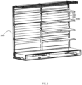
- the shelf system of this embodiment includes a back board 2000 and multiple shelves 3000 arranged e.g. one above the other as shown in Fig. 2 .
- the corresponding back board 2000 above each shelf 3000 is provided with a mounting hole 2001 to be connected to the first fixing member 101 of an associated fixed power supply unit 100.
- the back board 2000 comprises at least one strip-shaped through-hole or guiding slot 2002 extending in a longitudinal direction (which may be a vertical direction of the shelf system to be supplied with electric power), so that each sliding power supply unit 200 can be moved by sliding along the corresponding slot 2002 to a desired position, e.g. a desired vertical position of a shelf system, for power supply, and hence is movably installed on the strip-shaped hole or guiding slot 2002.
- the mounting hole 2001 may be embodied as a square hole, of a shape corresponding to the shaft of a T-shaped bump or protrusion of an associated first power supply unit to be fixed on the back board.
- the fixed power supply unit 100 is provided with a second socket 102 to enable a power supply in a shelf system, e.g. on the rear side or also front side of a back board of the shelf system..
- the fixed power supply unit 100 further comprises a second base 103 and a second top cover 104 connected to each other.
- One side of the second base 103 is provided with the second socket 102, and the second top cover 104 is connected to the second base 103 with a gap between them, with the first socket aligned with the second socket 102 and including two jacks 1041.
- the second base 103 and the second top cover 104 are connected through second connecting pieces 205 disposed on both sides of the second socket 102.
- the second connecting piece 205 serves also as the first fixing member 101, and the second connecting piece 205 can be fixed through the square hole on the back board 2000.
- the connectors in this embodiment may be in the form of buckles, etc., which are prior art and will not be described in detail.
Landscapes
- Mounting Of Printed Circuit Boards And The Like (AREA)
- Arrangement Of Elements, Cooling, Sealing, Or The Like Of Lighting Devices (AREA)
- Battery Mounting, Suspending (AREA)
Description
- The invention relates to the technical field of shelf systems comprising a power supply device.
- In the context of energy saving and environmental protection, LED lamps are more and more used in the fields of home and commercial lighting because of their high light emission efficiency and good light-gathering performance. Among them, shelf lighting is a kind of commercial lighting. In the installation of existing shelf lighting, there are problems of messy and scattered power wiring methods, complicated installation process, and time-consuming problems, and it takes up more shelf space after installation, resulting in unnecessary waste of space and the problem of low utilization rate. In order to solve these problems, it has been proposed to set up power supply rails (tracks) in shelves or shelf systems, which can be used with the power supply head to avoid messy and scattered power supply wiring. However, the power supply rails are usually all exposed, so that they can easily corrode and be damaged. Moreover, the power supply rails are not waterproof, so it is difficult to apply such shelves or shelf systems in areas under high moisture conditions and humidity, where watertightness is needed.
- Therefore, it is important to develop a waterproof and easy to install and dismantle power supply method and setup with important application value for power supply shelves and shelf systems with at least one power supply.
-
US 4 489 995 A discloses a shelf system, which is embodied as a refrigerated display cabinet comprising a vertical back board and a plurality of shelves mounted to the back board in a stacked configuration. At the front end of each shelf lighting fixtures are provided. For electric power supply, a central (fixed) power supply is provided, which is, however, not mounted to the back board but in a bottom air plenum of the display cabinet. - Vertical mounting slots are provided in the back board, in which electric outlet assemblies are slidably mounted, which consist of two parts and are mounted to each other and resiliently biased against each other.
- The electric outlet assemblies are electrically connected in series by means of electric lines, each having identical lengths, resulting in different lengths. The electric lines are not provided with at least one magnetic element to be attracted by the back board.
-
WO 2005/027278 A1 discloses a shelf system with conducting rails integrated into support columns and carriers. - It is an object of the present invention to provide a shelf system comprising a back board with stacked configuration of the shelves including a power supply shelf, configured to reliably provide electric power to at least one shelf of the shelf system with a low-cost set-up that can be assembled, disassembled and modified in a versatile manner. According to a further aspect of the present invention there is to be provided a method for supplying electric power to at least one shelf in such a shelf system comprising a back board.
- This problem is solved by a shelf system as claimed by claim 1, and by a method for supplying electric power to at least one shelf in such a shelf system as claimed by claim 11. Further advantageous embodiments are the subject-matter of the dependent claims.
- According to a further embodiment, the first fixing member may be a T-shaped bump or protrusion provided on one side of the fixed power supply unit, configured to be inserted into a corresponding mounting hole of a back board. More specifically, by first tilting the fixed power supply unit relative to the plane of the back board, then inserting one of the two arms of the T-shaped bump or protrusion, then the protrusion itself and then the second of the two arms of the T-shaped bump or protrusion and then tilting backward the fixed power supply unit so as to be disposed in parallel with the plane of the back board, the T-shaped bump or protrusion may be fixed in a positive-fit manner in the mounting hole of the back board, so as to be disposed fixed at the location of the mounting hole on the back board. As an alternative, the two arms of the T-shaped bump or protrusion may be resiliently biased against a shaft of the T-shaped bump or protrusion, and may be pushed inward towards the shaft so that the shaft may be inserted into a mounting hole of the back board, and after releasing the two arms again, they may return back to their biased home position, to thereby fix the fixed power supply unit in a positive-fit manner in the mounting hole of the back board.
- According to a further embodiment, the fixed power supply unit may be provided with a second socket, which may be disposed in particular on a side opposite to that side of the fixed power supply unit where the first socket is provided. Thus, power may also be supplied at the rear side of e.g. a back board of the shelf system.
- According to a further embodiment, the fixed power supply unit may further comprise: a second base, one side of which is provided with the second socket; and a second top cover connected to the second base with a space or gap formed therebetween, and having a second insertion hole aligned with the second socket.
- According to a further embodiment, the second base and the second top cover may be connected to each other through second connecting pieces arranged on both sides of the second socket.
- According to a further embodiment, the sliding power supply unit may comprise: a first base, one side of which is provided with the first socket; a first top cover connected to the first base with a space or gap formed therebetween, and having a first insertion hole 1 aligned with the first socket.
- According to a further embodiment, the first base and the first top cover may be connected through first connecting pieces arranged on both sides of the first socket.
- According to a further embodiment, a damping unit may be provided between the first base and the first top cover.
- According to a further embodiment, the mounting hole may be a square hole.
- According to a further embodiment, the power supply module may be provided with at least two fixed power supply units for each power supply module, and the fixed power supply units of each power supply module are electrically connected in sequence.
- The shelf system of the present invention have a simple structure, provide a convenient installation, are easy to disassemble and be modified, provide a good waterproof effect, are convenient in use, and provide excellent reliability and low manufacturing cost.
- Hereinafter, the invention will be described with reference to the accompanying drawings, wherein:
-
FIG. 1 is a schematic structural diagram of a power supply device for the shelf system according to the present invention; -
Fig. 2 is a schematic perspective front view of a shelf system of the present invention including a power supply module; -
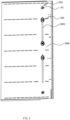
FIG. 3 is a partial structural schematic diagram of the back of the shelf system in the embodiment ofFig. 2 ; -
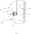
Fig. 4 is a partial structural schematic diagram of the front of the shelf system in the embodiment ofFig. 2 ; -
Fig. 5 is a partial exploded structure of the front of the shelf system in the embodiment ofFig. 2 ; -
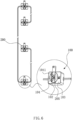
Fig. 6 is a schematic structural diagram of a power supply module of a shelf system according to a second embodiment of the present invention; -
Fig. 7 is a schematic diagram of a partial structure of a power supply module (front) of a shelf system according to another embodiment of the present invention; and -
Fig. 8 is a schematic diagram of a partial structure of a power supply module (back side) of a shelf system according to another embodiment of the present invention. - Throughout the drawings, the like reference numerals designate the same or technically equivalent members or groups of members.
- Specific embodiments of the present invention will be described in further detail below based on the accompanying drawings. It should be understood that the following description of the embodiments of the present invention shall not be construed to delimit the scope of protection of the present invention.
- As shown in
Figs. 1 to 5 , the power supply device of the claimed shelf system is generally suitable for supplying electric power to shelves. The power supply device includes twopower supply modules 1000, which are preferably electrically connected to each other by a common power supply wire or strip, as shown inFig. 3 . The total number of suchpower supply modules 1000 may be set e.g. according to the total number of layers (shelves) of the shelf system. Generally, onepower supply module 1000 may be provided for each layer of the shelf system. Of course, multiple layers orpower supply modules 1000 may also be set for a single layer. - Each
power supply module 1000 includes: a fixedpower supply unit 100 intended to be fixedly positioned, stationary, at a predetermined location of a back board as outlined hereinafter, a slidingpower supply unit 200 that can be moved on a back board by sliding to a desired position, if required, and a flexibleconductive strip 300, which electrically connects the fixedpower supply unit 100 and the associated slidingpower supply unit 200. The fixedpower supply unit 100 comprises afirst fixing member 101 and is connected to a power supply (not shown in the drawings). The slidingpower supply unit 200 comprises a first socket or plug-in interface 201 (seeFig. 5 ), and the two ends of the flexibleconductive strip 300 are electrically connected to the fixedpower supply unit 100 and the slidingpower supply unit 200, respectively. - After the
power supply module 1000 of this embodiment has been installed, e.g. fixedly mounted on a back board as outlined hereinafter in more detail, the fixedpower supply unit 100 is connected to an external power supply for power supply, whereas the slidingpower supply unit 200 can be moved relative to the fixedpower supply unit 100 by sliding, e.g. along grooves or slots provided in the back board, so as to provide a power supply function at a specific position as actually required by the geometry of the shelf system to be supplied with electric power, while the flexibleconductive strip 300 is bent accordingly by bending to supply electric power to the slidingpower supply unit 200. For this purpose, the length of the flexibleconductive strip 300 may basically correspond to the length of a longitudinal guidingslot back board 2000 plus the distance between the mounting position of the fixedpower supply unit 100 at the back board to the associated guidingslot Fig. 3 . - The fixed
power supply units 100 of eachpower supply module 1000 are electrically connected sequentially, and in this embodiment, thepower supply modules 1000 are electrically connected through the flexibleconductive strip 300, which is convenient for folding and transportation. - All the above-mentioned components can be conveniently completed to provide a waterproof setting, that is, a flexible waterproof layer may be wrapped on the outside of all the components of a
power supply module 1000. In this embodiment, the flexibleconductive strip 300 is a wire with an insulating layer applied directly upon it, and the waterproof effect can be realized as long as the insulating layer is waterproof. Other parts or components of thepower supply module 1000 are generally waterproofed by encapsulation. - According to the invention, the flexible
conductive strip 300 is provided with at least onemagnetic element 400. Themagnetic element 400 can be attracted by the back board of the shelf system including e.g. a ferro-magnetic layer, so that the flexibleconductive strip 300 can always maintain a general shape and does not project too far from the rear surface of the associatedback board 2000, and is not easily entangled. - The
first fixing member 101 should be easy to assemble and disassemble. In this embodiment, the first fixingmember 101 is embodied as a T-shaped bump arranged on one side of the fixedpower supply unit 100. The T-shaped bump may be fixedly mounted into a mounting hole of the back board, as outlined above. - In this embodiment, the sliding
power supply unit 200 includes at least the following: afirst base 202 provided with thefirst socket 201 on one side; a firsttop cover 203 connected to thefirst base 202 with a gap for accommodating aback board 2000 or similar holding plate, having afirst insertion hole 2031 aligned with thefirst socket 201. - In this embodiment, the
first base 202 and the firsttop cover 203 are connected through first connectingpieces 204 arranged on both sides of thefirst socket 201. In this embodiment, a damping unit is provided between thefirst base 202 and the firsttop cover 203 so as to maintain a positional relationship and gap between thefirst base 202 and the firsttop cover 203, e.g. including resilient members such as springs to resiliently bias thefirst base 202 and the firsttop cover 203 against each other. The damping unit may be also embodied as a plurality of protrusions, in particular elastic or resilient protrusions, but it may also be realized in a tight fit manner, and there are many ways, so that it is not necessary to go into the details. - The shelf system of this embodiment includes a
back board 2000 andmultiple shelves 3000 arranged e.g. one above the other as shown inFig. 2 . Thecorresponding back board 2000 above eachshelf 3000 is provided with a mountinghole 2001 to be connected to the first fixingmember 101 of an associated fixedpower supply unit 100. Moreover, theback board 2000 comprises at least one strip-shaped through-hole or guidingslot 2002 extending in a longitudinal direction (which may be a vertical direction of the shelf system to be supplied with electric power), so that each slidingpower supply unit 200 can be moved by sliding along thecorresponding slot 2002 to a desired position, e.g. a desired vertical position of a shelf system, for power supply, and hence is movably installed on the strip-shaped hole or guidingslot 2002. - In this embodiment, the mounting
hole 2001 may be embodied as a square hole, of a shape corresponding to the shaft of a T-shaped bump or protrusion of an associated first power supply unit to be fixed on the back board. - As shown in
Fig. 6 to 8 , in another embodiment, the fixedpower supply unit 100 is provided with asecond socket 102 to enable a power supply in a shelf system, e.g. on the rear side or also front side of a back board of the shelf system.. - The fixed
power supply unit 100 further comprises asecond base 103 and a secondtop cover 104 connected to each other. One side of thesecond base 103 is provided with thesecond socket 102, and the secondtop cover 104 is connected to thesecond base 103 with a gap between them, with the first socket aligned with thesecond socket 102 and including twojacks 1041. - The
second base 103 and the secondtop cover 104 are connected through second connectingpieces 205 disposed on both sides of thesecond socket 102. Here, the second connectingpiece 205 serves also as the first fixingmember 101, and the second connectingpiece 205 can be fixed through the square hole on theback board 2000. - The connectors in this embodiment may be in the form of buckles, etc., which are prior art and will not be described in detail.
- As will become apparent to the skilled person, the above describes only preferred exemplary embodiments of the present invention, and shall not be construed to delimit the scope of protection of the present invention.
Claims (11)
- A shelf system, comprising a back board (2000), a plurality of shelves (3000) mounted to the back board (2000) one above the other and supplied with electric power, and a power supply device for supplying electric power to the plurality of shelves (3000), wherein the power supply device comprises at least one power supply module (1000), whereinthe back board (2000) comprises a strip-shaped through-hole or guiding slot (2002) extending in a longitudinal direction, andeach power supply module (1000) comprises:a fixed power supply unit (100) having a first fixing member (101) and configured to be electrically connected to a power supply,at least one sliding power supply unit (200) having a first socket (201), each sliding power supply unit (200) being slidably mounted on an associated strip-shaped through-hole or guiding slot (2002), andat least one flexible conductive strip (300) the two ends of which are electrically connected to the fixed power supply unit (100) and the at least one sliding power supply unit (200), respectively; whereina mounting hole (2001) is associated to said strip-shaped through-hole or guiding slot (2002),the first fixing member (101) of each fixed power supply unit (100) is mounted to the associated mounting hole provided at the back board so as to fixedly mount the fixed power supply unit (100) at a fixed location at the back board (2000), andwherein each flexible conductive strip (300) is provided with at least one magnetic element (400) configured to be attracted by the back board (2000).
- The shelf system according to any of the preceding claims, wherein the first fixing member (101) is a T-shaped bump provided on one side of the fixed power supply unit (100).
- The shelf system according to any of the preceding claims, wherein the fixed power supply unit (100) of each power supply module (1000) is provided with a second socket (102).
- The shelf system according to claim 3, wherein the fixed power supply unit (100) of each power supply module (1000) further comprises:a second base (103), one side of which is provided with the second socket (102); anda second top cover (104) connected to the second base (103) with a space or gap formed therebetween, and having a second insertion hole (1041) aligned with the second socket (102).
- The shelf system according to claim 4, wherein the second base (103) and the second top cover (104) are connected to each other through second connecting pieces (205) arranged on both sides of the second socket (102).
- The shelf system according to any of the preceding claims, wherein each sliding power supply unit (200) comprises:a first base (202), one side of which is provided with the first socket (201);a first top cover (203) connected to the first base (202) with a space or gap formed therebetween, and having a first insertion hole (2031) aligned with the first socket (201).
- The shelf system according to claim 6, wherein the first base (202) and the first top cover (203) are connected through first connecting pieces (204) arranged on both sides of the first socket (201).
- The shelf system according to claim 7, wherein a damping unit is provided between the first base (202) and the first top cover (203).
- The shelf system according to claim 7, wherein the mounting hole (2001) is a square hole.
- The shelf system according to any of preceding claims 1 to 5, wherein the power supply module (1000) is provided with at least two fixed power supply units (100) for each power supply module (1000), and the fixed power supply units (100) of each power supply module (1000) are electrically connected in sequence.
- A method for supplying electric power to at least one shelf (3000) in a shelf system as claimed in any of claims 1 to 10, comprising the steps of:mounting the first fixing member (101) of each fixed power supply unit (100) to the associated mounting hole (2001) provided at the back board (2000) so as to fixedly mount the fixed power supply unit (100) at a fixed location at the back board (2000),slidably mounting each sliding power supply unit (200) of the at least one sliding power supply unit (200) of each power supply device to an associated strip-shaped through-hole or guiding slot (2002) and moving each sliding power supply unit (200) of the at least one sliding power supply unit (200) along said strip-shaped through-hole or guiding slot (2002) to a position corresponding to the position of an associated shelf (3000) of the shelf system, for suppling electric power to said associated shelf (3000).
Applications Claiming Priority (1)
| Application Number | Priority Date | Filing Date | Title |
|---|---|---|---|
| CN202111679853.9A CN114498221B (en) | 2021-12-31 | 2021-12-31 | Power supply device and power supply goods shelves |
Publications (2)
| Publication Number | Publication Date |
|---|---|
| EP4205606A1 EP4205606A1 (en) | 2023-07-05 |
| EP4205606B1 true EP4205606B1 (en) | 2024-11-13 |
Family
ID=81509287
Family Applications (1)
| Application Number | Title | Priority Date | Filing Date |
|---|---|---|---|
| EP22215028.6A Active EP4205606B1 (en) | 2021-12-31 | 2022-12-20 | Shelf system with power supply device |
Country Status (3)
| Country | Link |
|---|---|
| EP (1) | EP4205606B1 (en) |
| CN (1) | CN114498221B (en) |
| ES (1) | ES2995110T3 (en) |
Family Cites Families (10)
| Publication number | Priority date | Publication date | Assignee | Title |
|---|---|---|---|---|
| US4489995A (en) * | 1981-08-14 | 1984-12-25 | Tyler Refrigeration Corporation | Adjustable electrical outlet assembly |
| DE20314260U1 (en) * | 2003-09-15 | 2003-11-13 | Visplay International Ag, Muttenz | Profile rail and presentation device created with it |
| DE102014115986A1 (en) * | 2014-11-03 | 2016-05-04 | Hera Gmbh & Co. Kg | Device for power supply to be arranged on a shelf power consumers |
| CN116154696A (en) * | 2017-11-01 | 2023-05-23 | 无锡蜜蜂照明科技有限公司 | A rack built-in power-taking system |
| CN110492285B (en) * | 2019-07-12 | 2024-10-01 | 赛尔富电子有限公司 | Goods shelf power supply system |
| CN110707446A (en) * | 2019-10-08 | 2020-01-17 | 赛尔富电子有限公司 | A waterproof track type power taking system and power supply rack |
| CN110854633A (en) * | 2019-10-22 | 2020-02-28 | 赛尔富电子有限公司 | Power supply device for display and exhibition |
| CN111156479B (en) * | 2020-01-17 | 2025-03-11 | 苏州市华仓塑料有限公司 | A power supply and power supply system for lamp display board track |
| CN211743500U (en) * | 2020-05-07 | 2020-10-23 | 秦灿 | Novel goods shelf electricity taking system |
| CN112263114A (en) * | 2020-10-20 | 2021-01-26 | 刘林 | Light goods shelves |
-
2021
- 2021-12-31 CN CN202111679853.9A patent/CN114498221B/en active Active
-
2022
- 2022-12-20 ES ES22215028T patent/ES2995110T3/en active Active
- 2022-12-20 EP EP22215028.6A patent/EP4205606B1/en active Active
Also Published As
| Publication number | Publication date |
|---|---|
| EP4205606A1 (en) | 2023-07-05 |
| CN114498221B (en) | 2024-05-10 |
| ES2995110T3 (en) | 2025-02-06 |
| CN114498221A (en) | 2022-05-13 |
Similar Documents
| Publication | Publication Date | Title |
|---|---|---|
| EP3392976A1 (en) | Electrical supply and shelf system having the same | |
| US20130107441A1 (en) | Mounting apparatus for expansion cards | |
| US8894437B2 (en) | Systems and methods for connector enabling vertical removal | |
| CN107524965B (en) | Power taking system of goods shelf using LED lamp | |
| CN107528184B (en) | Independent electricity taking device and goods shelf using same | |
| CN113154291B (en) | A magnetic conductive track and lighting equipment | |
| EP3009739B1 (en) | Wall structure and lighting system using the same | |
| CN110459925B (en) | Telescopic power supply rail | |
| US10458629B2 (en) | Lighting module and lighting system | |
| US12016121B2 (en) | Interconnectable circuit boards adapted for three-dimensional constructions as lighting sources | |
| CN205811207U (en) | A kind of stand alone type electricity getting device and use the shelf of this electricity getting device | |
| CN111536450A (en) | Rail lamp system | |
| EP3782512B1 (en) | An electrical supply support arm and rack electrical supply system | |
| EP3391782B1 (en) | A shelf electrical supply and shelf electrical supply system having same | |
| CN104515046B (en) | A kind of combined lamp | |
| CN105143766B (en) | lighting system | |
| EP4205606A1 (en) | A power supply device for shelves and a power supply shelf | |
| CN211220772U (en) | Quick detach tray and robot | |
| CN102811585A (en) | electronic device | |
| CN110214474B (en) | Support element arrangement for electronic modules | |
| KR100831048B1 (en) | LED circuit board support and LED module assembly including the same | |
| WO2008059194A2 (en) | Methods and means of assembling electric/ electronic kits | |
| CN220235216U (en) | PCB trigger box | |
| CN219936950U (en) | Electric splicing type structural module | |
| CN221466865U (en) | Functional connector |
Legal Events
| Date | Code | Title | Description |
|---|---|---|---|
| PUAI | Public reference made under article 153(3) epc to a published international application that has entered the european phase |
Free format text: ORIGINAL CODE: 0009012 |
|
| STAA | Information on the status of an ep patent application or granted ep patent |
Free format text: STATUS: THE APPLICATION HAS BEEN PUBLISHED |
|
| AK | Designated contracting states |
Kind code of ref document: A1 Designated state(s): AL AT BE BG CH CY CZ DE DK EE ES FI FR GB GR HR HU IE IS IT LI LT LU LV MC ME MK MT NL NO PL PT RO RS SE SI SK SM TR |
|
| STAA | Information on the status of an ep patent application or granted ep patent |
Free format text: STATUS: REQUEST FOR EXAMINATION WAS MADE |
|
| 17P | Request for examination filed |
Effective date: 20230925 |
|
| RBV | Designated contracting states (corrected) |
Designated state(s): AL AT BE BG CH CY CZ DE DK EE ES FI FR GB GR HR HU IE IS IT LI LT LU LV MC ME MK MT NL NO PL PT RO RS SE SI SK SM TR |
|
| STAA | Information on the status of an ep patent application or granted ep patent |
Free format text: STATUS: EXAMINATION IS IN PROGRESS |
|
| 17Q | First examination report despatched |
Effective date: 20240508 |
|
| GRAP | Despatch of communication of intention to grant a patent |
Free format text: ORIGINAL CODE: EPIDOSNIGR1 |
|
| STAA | Information on the status of an ep patent application or granted ep patent |
Free format text: STATUS: GRANT OF PATENT IS INTENDED |
|
| GRAS | Grant fee paid |
Free format text: ORIGINAL CODE: EPIDOSNIGR3 |
|
| INTG | Intention to grant announced |
Effective date: 20240904 |
|
| GRAA | (expected) grant |
Free format text: ORIGINAL CODE: 0009210 |
|
| STAA | Information on the status of an ep patent application or granted ep patent |
Free format text: STATUS: THE PATENT HAS BEEN GRANTED |
|
| AK | Designated contracting states |
Kind code of ref document: B1 Designated state(s): AL AT BE BG CH CY CZ DE DK EE ES FI FR GB GR HR HU IE IS IT LI LT LU LV MC ME MK MT NL NO PL PT RO RS SE SI SK SM TR |
|
| REG | Reference to a national code |
Ref country code: GB Ref legal event code: FG4D |
|
| REG | Reference to a national code |
Ref country code: CH Ref legal event code: EP |
|
| REG | Reference to a national code |
Ref country code: IE Ref legal event code: FG4D |
|
| REG | Reference to a national code |
Ref country code: DE Ref legal event code: R096 Ref document number: 602022007693 Country of ref document: DE |
|
| REG | Reference to a national code |
Ref country code: ES Ref legal event code: FG2A Ref document number: 2995110 Country of ref document: ES Kind code of ref document: T3 Effective date: 20250206 |
|
| REG | Reference to a national code |
Ref country code: LT Ref legal event code: MG9D |
|
| REG | Reference to a national code |
Ref country code: NL Ref legal event code: MP Effective date: 20241113 |
|
| PG25 | Lapsed in a contracting state [announced via postgrant information from national office to epo] |
Ref country code: PT Free format text: LAPSE BECAUSE OF FAILURE TO SUBMIT A TRANSLATION OF THE DESCRIPTION OR TO PAY THE FEE WITHIN THE PRESCRIBED TIME-LIMIT Effective date: 20250313 Ref country code: HR Free format text: LAPSE BECAUSE OF FAILURE TO SUBMIT A TRANSLATION OF THE DESCRIPTION OR TO PAY THE FEE WITHIN THE PRESCRIBED TIME-LIMIT Effective date: 20241113 Ref country code: IS Free format text: LAPSE BECAUSE OF FAILURE TO SUBMIT A TRANSLATION OF THE DESCRIPTION OR TO PAY THE FEE WITHIN THE PRESCRIBED TIME-LIMIT Effective date: 20250313 |
|
| PG25 | Lapsed in a contracting state [announced via postgrant information from national office to epo] |
Ref country code: NL Free format text: LAPSE BECAUSE OF FAILURE TO SUBMIT A TRANSLATION OF THE DESCRIPTION OR TO PAY THE FEE WITHIN THE PRESCRIBED TIME-LIMIT Effective date: 20241113 Ref country code: FI Free format text: LAPSE BECAUSE OF FAILURE TO SUBMIT A TRANSLATION OF THE DESCRIPTION OR TO PAY THE FEE WITHIN THE PRESCRIBED TIME-LIMIT Effective date: 20241113 |
|
| REG | Reference to a national code |
Ref country code: AT Ref legal event code: MK05 Ref document number: 1740951 Country of ref document: AT Kind code of ref document: T Effective date: 20241113 |
|
| PG25 | Lapsed in a contracting state [announced via postgrant information from national office to epo] |
Ref country code: BG Free format text: LAPSE BECAUSE OF FAILURE TO SUBMIT A TRANSLATION OF THE DESCRIPTION OR TO PAY THE FEE WITHIN THE PRESCRIBED TIME-LIMIT Effective date: 20241113 |
|
| PG25 | Lapsed in a contracting state [announced via postgrant information from national office to epo] |
Ref country code: NO Free format text: LAPSE BECAUSE OF FAILURE TO SUBMIT A TRANSLATION OF THE DESCRIPTION OR TO PAY THE FEE WITHIN THE PRESCRIBED TIME-LIMIT Effective date: 20250213 |
|
| PG25 | Lapsed in a contracting state [announced via postgrant information from national office to epo] |
Ref country code: LV Free format text: LAPSE BECAUSE OF FAILURE TO SUBMIT A TRANSLATION OF THE DESCRIPTION OR TO PAY THE FEE WITHIN THE PRESCRIBED TIME-LIMIT Effective date: 20241113 Ref country code: AT Free format text: LAPSE BECAUSE OF FAILURE TO SUBMIT A TRANSLATION OF THE DESCRIPTION OR TO PAY THE FEE WITHIN THE PRESCRIBED TIME-LIMIT Effective date: 20241113 Ref country code: GR Free format text: LAPSE BECAUSE OF FAILURE TO SUBMIT A TRANSLATION OF THE DESCRIPTION OR TO PAY THE FEE WITHIN THE PRESCRIBED TIME-LIMIT Effective date: 20250214 |
|
| PG25 | Lapsed in a contracting state [announced via postgrant information from national office to epo] |
Ref country code: PL Free format text: LAPSE BECAUSE OF FAILURE TO SUBMIT A TRANSLATION OF THE DESCRIPTION OR TO PAY THE FEE WITHIN THE PRESCRIBED TIME-LIMIT Effective date: 20241113 |
|
| PG25 | Lapsed in a contracting state [announced via postgrant information from national office to epo] |
Ref country code: RS Free format text: LAPSE BECAUSE OF FAILURE TO SUBMIT A TRANSLATION OF THE DESCRIPTION OR TO PAY THE FEE WITHIN THE PRESCRIBED TIME-LIMIT Effective date: 20250213 |
|
| REG | Reference to a national code |
Ref country code: DE Ref legal event code: R119 Ref document number: 602022007693 Country of ref document: DE |
|
| PG25 | Lapsed in a contracting state [announced via postgrant information from national office to epo] |
Ref country code: SM Free format text: LAPSE BECAUSE OF FAILURE TO SUBMIT A TRANSLATION OF THE DESCRIPTION OR TO PAY THE FEE WITHIN THE PRESCRIBED TIME-LIMIT Effective date: 20241113 |
|
| PG25 | Lapsed in a contracting state [announced via postgrant information from national office to epo] |
Ref country code: DK Free format text: LAPSE BECAUSE OF FAILURE TO SUBMIT A TRANSLATION OF THE DESCRIPTION OR TO PAY THE FEE WITHIN THE PRESCRIBED TIME-LIMIT Effective date: 20241113 |
|
| PG25 | Lapsed in a contracting state [announced via postgrant information from national office to epo] |
Ref country code: EE Free format text: LAPSE BECAUSE OF FAILURE TO SUBMIT A TRANSLATION OF THE DESCRIPTION OR TO PAY THE FEE WITHIN THE PRESCRIBED TIME-LIMIT Effective date: 20241113 |
|
| PG25 | Lapsed in a contracting state [announced via postgrant information from national office to epo] |
Ref country code: RO Free format text: LAPSE BECAUSE OF FAILURE TO SUBMIT A TRANSLATION OF THE DESCRIPTION OR TO PAY THE FEE WITHIN THE PRESCRIBED TIME-LIMIT Effective date: 20241113 |
|
| PG25 | Lapsed in a contracting state [announced via postgrant information from national office to epo] |
Ref country code: SK Free format text: LAPSE BECAUSE OF FAILURE TO SUBMIT A TRANSLATION OF THE DESCRIPTION OR TO PAY THE FEE WITHIN THE PRESCRIBED TIME-LIMIT Effective date: 20241113 |
|
| PG25 | Lapsed in a contracting state [announced via postgrant information from national office to epo] |
Ref country code: CZ Free format text: LAPSE BECAUSE OF FAILURE TO SUBMIT A TRANSLATION OF THE DESCRIPTION OR TO PAY THE FEE WITHIN THE PRESCRIBED TIME-LIMIT Effective date: 20241113 |
|
| PG25 | Lapsed in a contracting state [announced via postgrant information from national office to epo] |
Ref country code: LU Free format text: LAPSE BECAUSE OF NON-PAYMENT OF DUE FEES Effective date: 20241220 |
|
| PG25 | Lapsed in a contracting state [announced via postgrant information from national office to epo] |
Ref country code: SE Free format text: LAPSE BECAUSE OF FAILURE TO SUBMIT A TRANSLATION OF THE DESCRIPTION OR TO PAY THE FEE WITHIN THE PRESCRIBED TIME-LIMIT Effective date: 20241113 |
|
| PG25 | Lapsed in a contracting state [announced via postgrant information from national office to epo] |
Ref country code: MC Free format text: LAPSE BECAUSE OF FAILURE TO SUBMIT A TRANSLATION OF THE DESCRIPTION OR TO PAY THE FEE WITHIN THE PRESCRIBED TIME-LIMIT Effective date: 20241113 |
|
| PLBE | No opposition filed within time limit |
Free format text: ORIGINAL CODE: 0009261 |
|
| STAA | Information on the status of an ep patent application or granted ep patent |
Free format text: STATUS: NO OPPOSITION FILED WITHIN TIME LIMIT |
|
| REG | Reference to a national code |
Ref country code: BE Ref legal event code: MM Effective date: 20241231 |
|
| PG25 | Lapsed in a contracting state [announced via postgrant information from national office to epo] |
Ref country code: DE Free format text: LAPSE BECAUSE OF NON-PAYMENT OF DUE FEES Effective date: 20250701 |
|
| PG25 | Lapsed in a contracting state [announced via postgrant information from national office to epo] |
Ref country code: BE Free format text: LAPSE BECAUSE OF NON-PAYMENT OF DUE FEES Effective date: 20241231 |
|
| PG25 | Lapsed in a contracting state [announced via postgrant information from national office to epo] |
Ref country code: FR Free format text: LAPSE BECAUSE OF NON-PAYMENT OF DUE FEES Effective date: 20250113 |
|
| 26N | No opposition filed |
Effective date: 20250814 |
|
| PG25 | Lapsed in a contracting state [announced via postgrant information from national office to epo] |
Ref country code: IE Free format text: LAPSE BECAUSE OF NON-PAYMENT OF DUE FEES Effective date: 20241220 |
|
| PGFP | Annual fee paid to national office [announced via postgrant information from national office to epo] |
Ref country code: ES Payment date: 20260119 Year of fee payment: 4 |
|
| PGFP | Annual fee paid to national office [announced via postgrant information from national office to epo] |
Ref country code: IT Payment date: 20251231 Year of fee payment: 4 |
|
| PG25 | Lapsed in a contracting state [announced via postgrant information from national office to epo] |
Ref country code: CY Free format text: LAPSE BECAUSE OF FAILURE TO SUBMIT A TRANSLATION OF THE DESCRIPTION OR TO PAY THE FEE WITHIN THE PRESCRIBED TIME-LIMIT Effective date: 20241113 |