EP4205600A1 - Brush for cleaning surfaces - Google Patents
Brush for cleaning surfaces Download PDFInfo
- Publication number
- EP4205600A1 EP4205600A1 EP22217324.7A EP22217324A EP4205600A1 EP 4205600 A1 EP4205600 A1 EP 4205600A1 EP 22217324 A EP22217324 A EP 22217324A EP 4205600 A1 EP4205600 A1 EP 4205600A1
- Authority
- EP
- European Patent Office
- Prior art keywords
- tufts
- bristles
- brush
- central support
- inclination
- Prior art date
- Legal status (The legal status is an assumption and is not a legal conclusion. Google has not performed a legal analysis and makes no representation as to the accuracy of the status listed.)
- Granted
Links
Images




Classifications
-
- A—HUMAN NECESSITIES
- A46—BRUSHWARE
- A46B—BRUSHES
- A46B9/00—Arrangements of the bristles in the brush body
- A46B9/02—Position or arrangement of bristles in relation to surface of the brush body, e.g. inclined, in rows, in groups
- A46B9/025—Position or arrangement of bristles in relation to surface of the brush body, e.g. inclined, in rows, in groups the bristles or the tufts being arranged in an angled position relative to each other
-
- A—HUMAN NECESSITIES
- A46—BRUSHWARE
- A46B—BRUSHES
- A46B9/00—Arrangements of the bristles in the brush body
- A46B9/02—Position or arrangement of bristles in relation to surface of the brush body, e.g. inclined, in rows, in groups
- A46B9/026—Position or arrangement of bristles in relation to surface of the brush body, e.g. inclined, in rows, in groups where the surface of the brush body or carrier is not in one plane, e.g. not flat
-
- A—HUMAN NECESSITIES
- A46—BRUSHWARE
- A46B—BRUSHES
- A46B9/00—Arrangements of the bristles in the brush body
- A46B9/02—Position or arrangement of bristles in relation to surface of the brush body, e.g. inclined, in rows, in groups
- A46B9/028—Bristle profile, the end of the bristle defining a surface other than a single plane or deviating from a simple geometric form, e.g. cylinder, sphere or cone
-
- A—HUMAN NECESSITIES
- A46—BRUSHWARE
- A46B—BRUSHES
- A46B2200/00—Brushes characterized by their functions, uses or applications
- A46B2200/30—Brushes for cleaning or polishing
- A46B2200/3066—Brush specifically designed for use with street cleaning machinery
Definitions
- the present invention concerns a brush for cleaning surfaces, in particular an industrial brush that can be used for cleaning surfaces in any productive and industrial sector, for street cleaning in the field of urban hygiene, therefore associated, for example, with appropriate cleaning machines, or other.
- brushes exist for cleaning surfaces, in particular cylindrical brushes which develop over a central support made of plastic, wood or metal material. Inside the support there may be a steel core to couple it to the automatic machine which transmits movement to the cylindrical brush.
- these brushes have a radial distribution of tufts of bristles, the bases of which are attached in suitable cavities which are made on the surface of the central support, following a pre-established distribution.
- patent application EP-A-1428456 describes a roller consisting of a central support which has a plurality of holes distributed on the external surface, with a constant pitch, for the insertion and attachment of respective tufts of bristles.
- the support consists of at least one cylindrical ring and the holes lie on planes orthogonal to the axis of the roller and are successively and alternatively inclined to one part and the other with respect to radial planes, or planes parallel to radial planes, passing through the axis of the cylinder and through the respective hole, in order to sweep two strips, lateral to the row of tufts, with the ends of the bristles.
- the brush based on this type of roller described in the above patent application although it has a certain cleaning efficiency, provides groups in which the tufts of bristles have substantially the same inclination when placed in sequence and therefore with respect to the same longitudinal section plane. In other words, the tufts of a given group are directed parallel to the tufts of any other group, with respect to the same longitudinal section plane.
- the cleaning or brushing performed using this type of brush provided with said roller can be perfected in terms of the homogeneity of the cleaning operation and in terms of the wear on the tufts of bristles, which could wear out in a non-uniform manner over time.
- known brushes show uneven wear of the tufts of bristles over time, that is, there are generally zones of the brush in which the tufts of bristles are considerably more worn than other tufts of bristles present in other zones of the brush. This naturally entails a progressive worsening of the cleaning efficiency of the brush.
- One purpose of the present invention is to provide a brush for cleaning surfaces which is efficient, simple to use, and which can guarantee homogeneous and effective cleaning or brushing even with a reduced number of passes.
- Another purpose of the present invention is to provide a brush for cleaning surfaces which, in addition to providing a homogeneous cleaning, can work substantially with the same efficiency over its whole active surface, consisting of the ends of the tufts of bristles which clean the surface, so that, moreover, it is subject to a homogeneous wear of the tufts of bristles over time.
- the Applicant has devised, tested and embodied the present invention to overcome the shortcomings of the state of the art and to obtain these and other purposes and advantages.
- a brush for cleaning surfaces comprises at least a central support and a plurality of tufts of bristles attached to the central support.
- the tufts of bristles are grouped into groups, wound according to a generatrix line or a closed winding path, or even an open and discontinuous winding path, around the central support, and configured to project outward from the central support.
- all the tufts of bristles which form a same group have the same inclination with respect to the central support, more precisely with respect to the external surface of the central support.
- the tufts of bristles are disposed according to an orderly disposition on the central support, that is, along longitudinal distribution directrices, preferably parallel to each other, which develop in a longitudinal direction of the brush, preferably homogeneously, between the opposite ends of the central support.
- the distribution directrices of the tufts of bristles between the opposite ends of the central support can follow the development of a straight line, or a broken line, or a curved line, having in particular a sinusoidal trend or a trend that contemplates the presence of a cusp about halfway between the opposite ends, or a mixed line formed by rectilinear and curvilinear segments.
- any one longitudinal distribution directrix of the tufts is defined between the opposite ends of the central support, along which the tufts of bristles are distributed.
- Each directrix comprises tufts of bristles belonging to at least two different groups, more preferably at least three different groups, having different inclinations from each other.
- this line can coincide with a longitudinal section plane of the brush, preferably a section plane oriented radially with respect to the central support, that is, incorporating a diametral segment thereof, and passing through its longitudinal axis.
- the present brush for cleaning surfaces is efficient, simple to use and guarantees a homogeneous cleaning or brushing even with a reduced number of cleaning passes and any inclination it is used with.
- the present brush for cleaning surfaces in addition to providing a homogeneous cleaning, can work with substantially the same efficiency along its entire active surface, formed by the ends of the plurality of tufts of bristles that clean the surface, so that it presents a peripheral cleaning surface equipped with substantially constant elasticity and uniform wear of the tufts of bristles over time, therefore without there being, on the circumference of the peripheral surface, more elastic zones alternating with less elastic zones and tufts of bristles markedly more worn than others.
- the tufts of bristles disposed aligned one after the other on the same distribution directrix are equidistant from each other. These tufts are inclined according to a respective inclination which is different from the inclination of the other tufts disposed on the same longitudinal directrix, each of these tufts belonging to different groups of bristles.
- the inclination of the tufts of bristles disposed aligned one after the other on the same longitudinal section plane has a trend, along the distribution directrix as above, such that, in a reference segment, the tufts of bristles start with a first inclination, progressively straighten, then progressively incline toward a second inclination, opposite the first inclination, straighten again, and then progressively incline with the first inclination.
- the tufts of bristles of one group vary their inclination by a preestablished angle, preferably comprised between 0.5° and 5°, in particular of about 1°, with respect to the inclination of the tufts of bristles of another group, in which the tufts are disposed adjacent, that is, consecutive one after the other along this distribution directrix.
- the inclinations of corresponding tufts of bristles disposed on different distribution directrices are different from each other, the corresponding tufts of bristles belonging to different groups.
- corresponding tufts of bristles we mean the tufts of bristles that have the same disposition on the distribution directrices, for example all the first tufts of bristles, all the second tufts of bristles, and so on.
- the winding path of the groups of tufts of bristles can be defined by cylindrical helixes and as stated, it can be closed or open and/or discontinuous.
- the pitch of each of the groups defined by cylindrical helixes can be constant.
- the pitch can be the same for all the groups of tufts of bristles.
- the central support can be substantially cylindrical in shape and have a circular or elliptical cross section, or suchlike.
- the central support can also comprise a plurality of seatings intended to fixedly receive and retain corresponding bases of the tufts of bristles; these seatings are made along respective generatrix lines that develop around the central support according to said path, for example a path having a helical or mixtilinear development.
- the winding path (or generatrix line) is evidently coherent with the development path of the groups of tufts of bristles around the central support.
- the central support can be either monolithic or formed by a series of annular segments, preferably, but not necessarily, modular and equal to each other, joined in coaxial succession along the longitudinal axis of the brush and joined to each other by means of joining means.
- a brush 20 for cleaning surfaces comprises at least a central support 13 which has a longitudinal axis L1, and on which tufts 14 of bristles are attached grouped into groups, each wound according to a helical winding path (or generatrix line), see for example fig. 7 , or a skew winding path, fig. 9 , around the central support 13.
- a helical winding path or generatrix line
- the tufts 14 are stably engaged in respective seatings 17 and project outward from the central support 13 which comprises two opposite ends, indicated by reference numbers 13a and 13b in the drawings.
- the central support 13 can be hollow and keyed to the shaft 16 ( fig. 1 ) of a drive system for the rotation of the brush 20, and preferably develops in an axial-symmetrical manner along the longitudinal axis L1 of the brush 20 and can have, for example, a cylindrical shape and a cross section with a circular profile, as shown by way of example, or have an elliptical profile or also a polygonal profile.
- the drive system provided with the shaft 16 can be, for example, an electric motor, or equivalent, of a cleaning machine with which the present brush 20 can be associated.
- the brush 20 can also be supported rotating idle on the cleaning machine.
- the tufts 14 of bristles are disposed according to an orderly disposition on the central support 13, being able to be either on planes passing through the longitudinal axis L1, or on planes skew with respect to the latter, as visible in fig. 9 .
- the tufts 14 of bristles are disposed along a plurality of longitudinal distribution directrices, indicated in the drawings with references P, P1, P2, P3, P4.
- the longitudinal distribution directrices P, P1, P2, P3, P4 develop parallel to each other and extend, preferably homogeneously, between the opposite ends 13a and 13b of the central support 13.
- the distribution directrices P, P1, P2, P3, P4 follow straight lines coinciding with as many longitudinal section planes of the brush 20. These planes are preferably oriented radially with respect to the central support 13 and, in the case of directrices parallel to the longitudinal axis L1, they incorporate a diametral segment thereof, while in the case of skew directrices they intersect it obliquely.
- the distribution directrices P, P1, P2, P3, P4 can be disposed on planes which are eccentric with respect to a plane passing through the longitudinal axis L1, as visible in fig. 4 .
- some directrices are disposed on planes which incorporate the longitudinal axis L1
- other directrices are disposed on planes which are eccentric with respect to such planes, that is, disposed parallel and offset with respect thereto.
- the distribution directrices have a disposition that is inclined with respect to the surface of the central support 13.
- a homogeneous inclination such as that shown in fig. 5 , advantageously allows to have a brush in which the tufts of bristles push against the surface to be cleaned if the brush is rotated in a first direction of rotation and, conversely, extend over this surface if it is rotated in a second direction of rotation, opposite to the first direction.
- Figs. from 11 to 14 show examples of other possible distribution directrices P1, P2 of the tufts 14 of bristles, all falling within the scope of protection of the present invention.
- fig. 9 shows distribution directrices P1, P2 which follow straight lines defining the same amount of longitudinal section planes of the brush 20.
- the section planes are inclined, that is, skew, with respect to the longitudinal axis L1, which, as mentioned, intersects these planes without being contained therein.
- Fig. 11 shows distribution directrices P1, P2 having a trend that follows a broken line; fig. 12 a trend that follows a sinusoidal curvilinear line; fig. 13 a trend that follows a curvilinear line with a cusp; fig. 14 a trend that follows a mixed line formed by rectilinear segments and curvilinear segments.
- the lines 1 which intersect the directrices P1, P2 contain tufts of bristles which have the same inclinations.
- the present brush 20 comprises at least two groups 15a, 15n of tufts 14a-14n in which the tufts 14a-14n of bristles have different inclinations A1-An with respect to any longitudinal section plane whatsoever of the brush 20.
- the tufts 14a of bristles of the group 15a are inclined according to a first inclination A1, different from a second inclination An, according to which the tufts 14n of bristles of the group 15n are instead inclined.
- the brush 20 By sectioning the brush 20 with any one of said longitudinal section planes, for example the plane P1, it is possible to visualize the plurality of tufts of bristles which are disposed aligned in a row, along the same longitudinal distribution directrix, that is, along the same section plane, and which are inclined differently from each other ( fig. 6 ).
- the tufts 14 of bristles located on opposite parts with respect to the axis L1 of the central support 13 have an opposite inclination.
- the inclination of each tuft of bristles of the row of bristles disposed above the longitudinal axis L1 is opposite to the inclination of the corresponding tuft of bristles of the row of bristles disposed below the longitudinal axis L1: in other words, if in the row of bristles disposed above these are inclined by +20°, those disposed below are inclined by -20° with respect to the vertical.
- the tufts 14a of bristles of a same group 15a can be inclined differently from the tufts 14b of an adjacent group 15b, with respect to a same section plane, for example the plane P1 or the plane P2, as can be seen in fig. 6 (with reference to the plane P1).
- the tufts of bristles 14a therefore have an inclination A1 different from the inclination A2 of the tufts 14b, and so on for all the other groups of tufts of bristles.
- the inclination of the tufts 14 of bristles is such as to keep the tufts within the longitudinal section plane.
- the tufts 14 are inclined exclusively along planes that are perpendicular with respect to the distribution directrices identified by the planes P1, P2 in the drawing.
- Fig. 8B shows another embodiment provided as a non-limiting example, in which the tufts 14 are inclined according to two different directions, being a combination of the embodiments shown in figs. 6 and 8A , that is, a mixed inclination in which there is both a longitudinal component (parallel to the longitudinal axis L1), and also a transverse component (perpendicular to the longitudinal axis L1).
- the tufts of adjacent bristles can have the same inclination, in groups of two by two, or three by three, etc.
- the inclination of the tufts 14 of bristles located aligned one after the other on the same longitudinal section plane P, P1, P2, P3, P4 has a trend, along the longitudinal axis L1, such that starting from one of the ends 13a, the tufts 14 of bristles are inclined according to a first inclination A1, they progressively straighten, then progressively incline according to a second inclination, for example the inclination An, opposite to the first inclination A1, they straighten again and then progressively incline according to the first inclination A1 in proximity to the other end 13b.
- the above distribution of the tufts 14 of bristles in the various groups 15 allows to obtain an extremely effective brush 20, able to clean a surface in an extremely uniform and homogeneous manner, also ensuring a uniform wear of the tufts 14 of bristles.
- the distribution of the tufts 14 of bristles of the various groups 15 ordered according to the possible embodiments of the invention allows to obtain a brush 20 the overall external cleaning surface of which, that is, the surface intended to be placed in contact with the surface to be cleaned, has a substantially homogeneous elasticity, as can be seen directly from the graph in fig. 10 , in which the modulus of elasticity of the bristles of one of the distribution directrix lines is indicated on the ordinate axis, while the length of the support 13 is indicated on the abscissa axis.
- the tufts 14a of bristles of a determinate group 15a can vary their inclination by about 1° with respect to the tufts 14b of an adjacent group 15b, according to a same longitudinal section plane P1 of the brush 20. This can obviously occur for any adjacent pair of tufts 14, wherein the tufts incline, straighten, counter-incline, straighten, and once again incline progressively, whereby each inclination, counter-inclination or straightening pitch can be of about 1°.
- the planes P1 and P2 are the traces of any two contiguous distribution directrices, and the pin-like symbols that rise from these represent the ideal longitudinal axes of the tufts 14.
- the inclination of the first tuft of bristles disposed on a section plane, with respect to the corresponding first tuft 14 of bristles disposed on an adjacent section plane varies by a determinate angle, for example of a few degrees.
- this angle is comprised between 0.5° and 5°, in particular equal to about 1°.
- the same is valid for all the second tufts of bristles disposed on consecutive section planes, for all the third tufts of bristles, and so on, coherently with the helical development configuration, described in more detail below with particular reference to fig. 7 .
- the groups 15 of tufts 14 characterized by the same inclination can follow a development path with a helical trend along the central support 13 which, as visible in fig. 7 , is circumferentially closed.
- these groups 15 can be defined by cylindrical helices wound around the central support 13. These cylindrical helices could also be obtained by approximation by means of sequences of segments, for example rectilinear, of tufts 14 of bristles.
- Fig. 7 is an example of a cylindrical support 13 which illustrates two groups 15 defined by cylindrical helices, identified by the letters "a" and "n".
- the pitch X of these groups 15 is constant. Furthermore, this pitch X is preferably the same for all the groups 15.
- the central support 13 can have a substantially cylindrical shape and a cylindrical, elliptical, conical, regular or irregular cross section, or even a combination thereof.
- This central support 13 can comprise a plurality of seatings 17, for example created transversely on the external surface of the central support 13 and intended to fixedly receive and retain corresponding bases 18 of the tufts 14 of bristles.
- the seatings 17 can be created along respective generatrix lines that develop around the central support 13 according to a helical winding path, however never annular, that is, never perpendicular to the longitudinal axis L1. See for example part of the generatrix line 19 highlighted in fig. 7 , in this case by way of example with a helical shape. These generatrix lines therefore substantially define the development path of the groups 15 of tufts 14 of bristles on the central support 13.
- the winding path can comprise rectilinear, curvilinear or mixtilinear segments, one or more of these segments extending according to an orientation that can also be skew with respect to the longitudinal axis L1.
- the central support 13 could also be formed by a series of annular segments 21 ( fig. 7 ) located in succession along the longitudinal axis L1 and joined to each other by means of suitable joining means, not shown.
- the annular segments 21 could be modular, that is, all the same as each other, or have different lengths.
Landscapes
- Physics & Mathematics (AREA)
- Geometry (AREA)
- Brushes (AREA)
- Motor Or Generator Current Collectors (AREA)
- Polishing Bodies And Polishing Tools (AREA)
Abstract
Description
- The present invention concerns a brush for cleaning surfaces, in particular an industrial brush that can be used for cleaning surfaces in any productive and industrial sector, for street cleaning in the field of urban hygiene, therefore associated, for example, with appropriate cleaning machines, or other.
- It is known that brushes exist for cleaning surfaces, in particular cylindrical brushes which develop over a central support made of plastic, wood or metal material. Inside the support there may be a steel core to couple it to the automatic machine which transmits movement to the cylindrical brush.
- In the field of brushes for industrial, road or other use, large cylindrical brushes are known, with tufts of bristles, or filaments, even 30 centimeters long and even having widths in the order of more than four meters, which are mounted and driven rotatable around a horizontal axis for cleaning and treating any surface, for example, courtyards, streets, squares, industrial warehouses or suchlike.
- Typically, these brushes have a radial distribution of tufts of bristles, the bases of which are attached in suitable cavities which are made on the surface of the central support, following a pre-established distribution.
- For example, patent application
EP-A-1428456 describes a roller consisting of a central support which has a plurality of holes distributed on the external surface, with a constant pitch, for the insertion and attachment of respective tufts of bristles. The support consists of at least one cylindrical ring and the holes lie on planes orthogonal to the axis of the roller and are successively and alternatively inclined to one part and the other with respect to radial planes, or planes parallel to radial planes, passing through the axis of the cylinder and through the respective hole, in order to sweep two strips, lateral to the row of tufts, with the ends of the bristles. - The brush based on this type of roller described in the above patent application, although it has a certain cleaning efficiency, provides groups in which the tufts of bristles have substantially the same inclination when placed in sequence and therefore with respect to the same longitudinal section plane. In other words, the tufts of a given group are directed parallel to the tufts of any other group, with respect to the same longitudinal section plane.
- The cleaning or brushing performed using this type of brush provided with said roller can be perfected in terms of the homogeneity of the cleaning operation and in terms of the wear on the tufts of bristles, which could wear out in a non-uniform manner over time.
- In general, therefore, current brushes for cleaning surfaces scarcely guarantee a homogeneous cleaning such that the brush can work substantially with homogeneous characteristics for its whole active surface, consisting of the ends of the tufts of bristles which clean the surface to be cleaned.
- Furthermore, known brushes show uneven wear of the tufts of bristles over time, that is, there are generally zones of the brush in which the tufts of bristles are considerably more worn than other tufts of bristles present in other zones of the brush. This naturally entails a progressive worsening of the cleaning efficiency of the brush.
- Moreover, with normal brushes, in order to have a homogeneous and satisfactory brushing action, it is necessary to carry out repeated passes of the brushes over the same zone of the surfaces to be brushed.
- This requirement causes a lengthening of the operating times which negatively affects the diligence of the operators and the general performance of the brushing machines.
- There is therefore a need to perfect an industrial brush which can overcome at least one of the disadvantages of the state of the art.
- One purpose of the present invention is to provide a brush for cleaning surfaces which is efficient, simple to use, and which can guarantee homogeneous and effective cleaning or brushing even with a reduced number of passes.
- Another purpose of the present invention is to provide a brush for cleaning surfaces which, in addition to providing a homogeneous cleaning, can work substantially with the same efficiency over its whole active surface, consisting of the ends of the tufts of bristles which clean the surface, so that, moreover, it is subject to a homogeneous wear of the tufts of bristles over time.
- The Applicant has devised, tested and embodied the present invention to overcome the shortcomings of the state of the art and to obtain these and other purposes and advantages.
- The present invention is set forth and characterized in the independent claims. The dependent claims describe other characteristics of the present invention or variants to the main inventive idea.
- For a better and quicker understanding of the following description, we first outline the definitions of the expressions that have been used:
- a tuft is a set of bristles inserted in a single hollow seating obtained in a central support;
- a group of tufts is a set of tufts of bristles that have the same inclination with respect to the central support;
- a longitudinal distribution directrix is an ideal line which extends longitudinally along the central support, between two opposite ends thereof, and which comprises tufts of bristles which have different inclinations to each other;
- a generatrix line is an ideal line along which tufts of bristles are disposed which have the same inclination, that is, along which a group of tufts is disposed;
- a winding path is a path of each group of tufts, that is, a path along which tufts of bristles are disposed which have the same inclination with respect to the central support; in other words, each winding path coincides with a respective generatrix line and in the following description these two expressions are used interchangeably.
- In accordance with the above purposes, a brush for cleaning surfaces according to the present invention comprises at least a central support and a plurality of tufts of bristles attached to the central support. The tufts of bristles are grouped into groups, wound according to a generatrix line or a closed winding path, or even an open and discontinuous winding path, around the central support, and configured to project outward from the central support. As stated, all the tufts of bristles which form a same group have the same inclination with respect to the central support, more precisely with respect to the external surface of the central support.
- The tufts of bristles are disposed according to an orderly disposition on the central support, that is, along longitudinal distribution directrices, preferably parallel to each other, which develop in a longitudinal direction of the brush, preferably homogeneously, between the opposite ends of the central support.
- By way of a non-limiting example, the distribution directrices of the tufts of bristles between the opposite ends of the central support can follow the development of a straight line, or a broken line, or a curved line, having in particular a sinusoidal trend or a trend that contemplates the presence of a cusp about halfway between the opposite ends, or a mixed line formed by rectilinear and curvilinear segments. According to one aspect of the invention, any one longitudinal distribution directrix of the tufts is defined between the opposite ends of the central support, along which the tufts of bristles are distributed. Each directrix comprises tufts of bristles belonging to at least two different groups, more preferably at least three different groups, having different inclinations from each other.
- By way of a non-limiting example, if the distribution directrix of the tufts follows a straight line, this line can coincide with a longitudinal section plane of the brush, preferably a section plane oriented radially with respect to the central support, that is, incorporating a diametral segment thereof, and passing through its longitudinal axis.
- Advantageously, the present brush for cleaning surfaces is efficient, simple to use and guarantees a homogeneous cleaning or brushing even with a reduced number of cleaning passes and any inclination it is used with.
- The present brush for cleaning surfaces, in addition to providing a homogeneous cleaning, can work with substantially the same efficiency along its entire active surface, formed by the ends of the plurality of tufts of bristles that clean the surface, so that it presents a peripheral cleaning surface equipped with substantially constant elasticity and uniform wear of the tufts of bristles over time, therefore without there being, on the circumference of the peripheral surface, more elastic zones alternating with less elastic zones and tufts of bristles markedly more worn than others.
- According to another aspect of the invention, the tufts of bristles disposed aligned one after the other on the same distribution directrix are equidistant from each other. These tufts are inclined according to a respective inclination which is different from the inclination of the other tufts disposed on the same longitudinal directrix, each of these tufts belonging to different groups of bristles.
- In some embodiments of the present brush, the inclination of the tufts of bristles disposed aligned one after the other on the same longitudinal section plane has a trend, along the distribution directrix as above, such that, in a reference segment, the tufts of bristles start with a first inclination, progressively straighten, then progressively incline toward a second inclination, opposite the first inclination, straighten again, and then progressively incline with the first inclination.
- In some embodiments of the present brush, on the same distribution directrix, the tufts of bristles of one group vary their inclination by a preestablished angle, preferably comprised between 0.5° and 5°, in particular of about 1°, with respect to the inclination of the tufts of bristles of another group, in which the tufts are disposed adjacent, that is, consecutive one after the other along this distribution directrix.
- According to another aspect, the inclinations of corresponding tufts of bristles disposed on different distribution directrices are different from each other, the corresponding tufts of bristles belonging to different groups.
- By the expression "corresponding tufts of bristles" we mean the tufts of bristles that have the same disposition on the distribution directrices, for example all the first tufts of bristles, all the second tufts of bristles, and so on.
- The winding path of the groups of tufts of bristles can be defined by cylindrical helixes and as stated, it can be closed or open and/or discontinuous.
- The pitch of each of the groups defined by cylindrical helixes can be constant.
- Moreover, the pitch can be the same for all the groups of tufts of bristles.
- In some embodiments, the central support can be substantially cylindrical in shape and have a circular or elliptical cross section, or suchlike.
- The central support can also comprise a plurality of seatings intended to fixedly receive and retain corresponding bases of the tufts of bristles; these seatings are made along respective generatrix lines that develop around the central support according to said path, for example a path having a helical or mixtilinear development. The winding path (or generatrix line) is evidently coherent with the development path of the groups of tufts of bristles around the central support.
- The central support can be either monolithic or formed by a series of annular segments, preferably, but not necessarily, modular and equal to each other, joined in coaxial succession along the longitudinal axis of the brush and joined to each other by means of joining means.
- These and other aspects, characteristics and advantages of the present invention will become apparent from the following description of some embodiments, given as a non-restrictive example with reference to the attached drawings wherein:
-
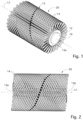
fig. 1 is a three-dimensional view of a brush for cleaning surfaces according to the present invention in which at least one winding path, or generatrix line, is highlighted, along which there are disposed tufts having the same inclination; -
fig. 2 is a lateral view of the brush offig. 1 ; -
fig. 3 is a front view of the brush offig. 2 ; -
fig. 4 is a front view of the brush according to the invention and according to a possible alternative disposition of the tufts of bristles; -
fig. 5 is a front view of the brush according to the invention and according to another possible alternative disposition of the tufts of bristles; -
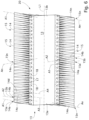
fig. 6 is a longitudinal section view of the brush, considered according to any longitudinal section plane whatsoever, for example according to the plane with outline VI-VI offig. 3 ; -
fig. 7 is a schematic view of a first version of a pattern of disposition of tufts of bristles on two winding paths of a central support of the brush according to the present invention, stripped of all the other tufts; -
fig. 8A is a schematic and interrupted view of a possible version which shows an example disposition of the tufts on a portion of a central support of the brush according to the invention; -
fig. 8B is a schematic and interrupted view of another possible version which shows another example disposition of the tufts on a portion of a central support of the brush according to the invention; -
fig. 9 is a schematic view of a portion of a central support rendered in a horizontal plane and in which the tufts of bristles are disposed along distribution directrices that are skew with respect to the longitudinal axis of the brush; -
fig. 10 is a graph which qualitatively shows the trend of the modulus of elasticity of the tufts of bristles as a function of the length of a central support, both for the prior art and also for the invention; - figs. from 11 to 14 show other disposition patterns of tufts of bristles on a central support of the brush according to the invention;
-
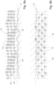
figs. 15 and 16 show, very schematically, the central axes of tufts of bristles disposed along two contiguous distribution directrices. - To facilitate comprehension, the same reference numbers have been used, where possible, to identify identical common elements in the drawings. It is understood that elements and characteristics of one embodiment can be conveniently combined or incorporated into other embodiments without further clarifications.
- We will now refer in detail to the possible embodiments of the invention, of which one or more examples are shown in the attached drawings, by way of a non-limiting illustration. The phraseology and terminology used here is also for the purposes of providing non-limiting examples.
- With reference to the attached drawings, see for example
figs. 1-3 , abrush 20 for cleaning surfaces according to the present invention comprises at least acentral support 13 which has a longitudinal axis L1, and on whichtufts 14 of bristles are attached grouped into groups, each wound according to a helical winding path (or generatrix line), see for examplefig. 7 , or a skew winding path,fig. 9 , around thecentral support 13. - The
tufts 14 are stably engaged inrespective seatings 17 and project outward from thecentral support 13 which comprises two opposite ends, indicated byreference numbers - The
central support 13 can be hollow and keyed to the shaft 16 (fig. 1 ) of a drive system for the rotation of thebrush 20, and preferably develops in an axial-symmetrical manner along the longitudinal axis L1 of thebrush 20 and can have, for example, a cylindrical shape and a cross section with a circular profile, as shown by way of example, or have an elliptical profile or also a polygonal profile. - The drive system provided with the
shaft 16 can be, for example, an electric motor, or equivalent, of a cleaning machine with which thepresent brush 20 can be associated. - In an alternative embodiment, the
brush 20 can also be supported rotating idle on the cleaning machine. - The
tufts 14 of bristles are disposed according to an orderly disposition on thecentral support 13, being able to be either on planes passing through the longitudinal axis L1, or on planes skew with respect to the latter, as visible infig. 9 . - Specifically, the
tufts 14 of bristles are disposed along a plurality of longitudinal distribution directrices, indicated in the drawings with references P, P1, P2, P3, P4. - Preferably, the longitudinal distribution directrices P, P1, P2, P3, P4 develop parallel to each other and extend, preferably homogeneously, between the opposite ends 13a and 13b of the
central support 13. - With reference to the embodiment shown in the drawings, the distribution directrices P, P1, P2, P3, P4 follow straight lines coinciding with as many longitudinal section planes of the
brush 20. These planes are preferably oriented radially with respect to thecentral support 13 and, in the case of directrices parallel to the longitudinal axis L1, they incorporate a diametral segment thereof, while in the case of skew directrices they intersect it obliquely. - However, according to a possible alternative embodiment, the distribution directrices P, P1, P2, P3, P4 can be disposed on planes which are eccentric with respect to a plane passing through the longitudinal axis L1, as visible in
fig. 4 . In this version, some directrices are disposed on planes which incorporate the longitudinal axis L1, while other directrices are disposed on planes which are eccentric with respect to such planes, that is, disposed parallel and offset with respect thereto. - With reference to the embodiment shown in
fig. 5 , in this case the distribution directrices have a disposition that is inclined with respect to the surface of thecentral support 13. A homogeneous inclination, such as that shown infig. 5 , advantageously allows to have a brush in which the tufts of bristles push against the surface to be cleaned if the brush is rotated in a first direction of rotation and, conversely, extend over this surface if it is rotated in a second direction of rotation, opposite to the first direction. - Figs. from 11 to 14 show examples of other possible distribution directrices P1, P2 of the
tufts 14 of bristles, all falling within the scope of protection of the present invention. - Specifically,
fig. 9 shows distribution directrices P1, P2 which follow straight lines defining the same amount of longitudinal section planes of thebrush 20. However, unlike the embodiment described with reference tofigs. 1-3 ,6 and7 , in this example the section planes are inclined, that is, skew, with respect to the longitudinal axis L1, which, as mentioned, intersects these planes without being contained therein. -
Fig. 11 shows distribution directrices P1, P2 having a trend that follows a broken line;fig. 12 a trend that follows a sinusoidal curvilinear line;fig. 13 a trend that follows a curvilinear line with a cusp;fig. 14 a trend that follows a mixed line formed by rectilinear segments and curvilinear segments. - Consequently, the
lines 1 which intersect the directrices P1, P2 contain tufts of bristles which have the same inclinations. - The person of skill in the art will understand that in these particular solutions, the distribution directrices and the generatrix lines can be exchanged with each other.
- In the continuation of the detailed description, for simplicity we will refer to the example shown in
figs. 1-3 ,6 ,7 and therefore we will refer to longitudinal distribution directrices of thetufts 14 of bristles configured as longitudinal section planes of thebrush 20, whereby the references P, P1, P2, P3, P4 will indifferently indicate both the longitudinal distribution directrices as well as the longitudinal section planes which define such directrices in the example described here in detail. - The
present brush 20, see for examplefigs. 6 and7 , comprises at least twogroups tufts 14a-14n in which thetufts 14a-14n of bristles have different inclinations A1-An with respect to any longitudinal section plane whatsoever of thebrush 20. - For example, as can be seen in
fig. 6 , in the half-section of thecentral support 13, respectively upper and lower with respect to the axis L1, thetufts 14a of bristles of thegroup 15a are inclined according to a first inclination A1, different from a second inclination An, according to which thetufts 14n of bristles of thegroup 15n are instead inclined. - By sectioning the
brush 20 with any one of said longitudinal section planes, for example the plane P1, it is possible to visualize the plurality of tufts of bristles which are disposed aligned in a row, along the same longitudinal distribution directrix, that is, along the same section plane, and which are inclined differently from each other (fig. 6 ). - As can be observed, with respect to a same longitudinal section plane of the
brush 20, thetufts 14 of bristles located on opposite parts with respect to the axis L1 of thecentral support 13 have an opposite inclination. With reference to the section offig. 6 , it can be seen that the inclination of each tuft of bristles of the row of bristles disposed above the longitudinal axis L1 is opposite to the inclination of the corresponding tuft of bristles of the row of bristles disposed below the longitudinal axis L1: in other words, if in the row of bristles disposed above these are inclined by +20°, those disposed below are inclined by -20° with respect to the vertical. - In the
present brush 20, thetufts 14a of bristles of asame group 15a can be inclined differently from thetufts 14b of anadjacent group 15b, with respect to a same section plane, for example the plane P1 or the plane P2, as can be seen infig. 6 (with reference to the plane P1). The tufts ofbristles 14a therefore have an inclination A1 different from the inclination A2 of thetufts 14b, and so on for all the other groups of tufts of bristles. In this example, the inclination of thetufts 14 of bristles is such as to keep the tufts within the longitudinal section plane. - In another example embodiment, shown in
fig. 8A , thetufts 14 are inclined exclusively along planes that are perpendicular with respect to the distribution directrices identified by the planes P1, P2 in the drawing. -
Fig. 8B shows another embodiment provided as a non-limiting example, in which thetufts 14 are inclined according to two different directions, being a combination of the embodiments shown infigs. 6 and8A , that is, a mixed inclination in which there is both a longitudinal component (parallel to the longitudinal axis L1), and also a transverse component (perpendicular to the longitudinal axis L1). - In other embodiments, not shown but entirely equivalent, it can be provided that on the same section plane P the tufts of adjacent bristles can have the same inclination, in groups of two by two, or three by three, etc.
- In the
present brush 20 and along thecentral support 13, the inclination of thetufts 14 of bristles located aligned one after the other on the same longitudinal section plane P, P1, P2, P3, P4 has a trend, along the longitudinal axis L1, such that starting from one of theends 13a, thetufts 14 of bristles are inclined according to a first inclination A1, they progressively straighten, then progressively incline according to a second inclination, for example the inclination An, opposite to the first inclination A1, they straighten again and then progressively incline according to the first inclination A1 in proximity to theother end 13b. - The above distribution of the
tufts 14 of bristles in thevarious groups 15 allows to obtain an extremelyeffective brush 20, able to clean a surface in an extremely uniform and homogeneous manner, also ensuring a uniform wear of thetufts 14 of bristles. - Furthermore, the distribution of the
tufts 14 of bristles of thevarious groups 15 ordered according to the possible embodiments of the invention allows to obtain abrush 20 the overall external cleaning surface of which, that is, the surface intended to be placed in contact with the surface to be cleaned, has a substantially homogeneous elasticity, as can be seen directly from the graph infig. 10 , in which the modulus of elasticity of the bristles of one of the distribution directrix lines is indicated on the ordinate axis, while the length of thesupport 13 is indicated on the abscissa axis. - For precision, we must underline that the straight line of the graph drawn with alternating segments and points qualitatively represents the (constant) modulus of elasticity of a distribution directrix of a known type, while the curved lines each indicate, again qualitatively, the trend of the (non-constant) moduli of elasticity of a distribution directrix according to the invention.
- In some embodiments, the
tufts 14a of bristles of adeterminate group 15a can vary their inclination by about 1° with respect to thetufts 14b of anadjacent group 15b, according to a same longitudinal section plane P1 of thebrush 20. This can obviously occur for any adjacent pair oftufts 14, wherein the tufts incline, straighten, counter-incline, straighten, and once again incline progressively, whereby each inclination, counter-inclination or straightening pitch can be of about 1°. - Moreover, it is provided that the inclination of tufts of corresponding bristles disposed on adjacent section planes is offset. This effect is visible in the enlarged and schematic detail of
figs. 15 and 16 , in which this effect has been significantly exaggerated for the benefit of a clearer disclosure. - In detail, in these
figs. 15 and 16 the planes P1 and P2 are the traces of any two contiguous distribution directrices, and the pin-like symbols that rise from these represent the ideal longitudinal axes of thetufts 14. - Purely by way of example, a progressive number has been indicated for each pin-like symbol, preceded by a "-" or "+" sign so that it is possible to immediately visualize the inclinations and counter-inclinations of two rows of
tufts 14 disposed on a respective distribution directrix. - Please note, in particular, that the distribution of the
tufts 14 of each distribution directrix, for example P1, and that of the adjacent distribution directrix P2 are reciprocally longitudinally offset by a value "Q". - The inclination of the first tuft of bristles disposed on a section plane, with respect to the corresponding
first tuft 14 of bristles disposed on an adjacent section plane, varies by a determinate angle, for example of a few degrees. Preferably, this angle is comprised between 0.5° and 5°, in particular equal to about 1°. The same is valid for all the second tufts of bristles disposed on consecutive section planes, for all the third tufts of bristles, and so on, coherently with the helical development configuration, described in more detail below with particular reference tofig. 7 . - As mentioned, the
groups 15 oftufts 14 characterized by the same inclination can follow a development path with a helical trend along thecentral support 13 which, as visible infig. 7 , is circumferentially closed. In some embodiments, thesegroups 15 can be defined by cylindrical helices wound around thecentral support 13. These cylindrical helices could also be obtained by approximation by means of sequences of segments, for example rectilinear, oftufts 14 of bristles. -
Fig. 7 is an example of acylindrical support 13 which illustrates twogroups 15 defined by cylindrical helices, identified by the letters "a" and "n". The pitch X of thesegroups 15 is constant. Furthermore, this pitch X is preferably the same for all thegroups 15. - The
central support 13 can have a substantially cylindrical shape and a cylindrical, elliptical, conical, regular or irregular cross section, or even a combination thereof. - This
central support 13 can comprise a plurality ofseatings 17, for example created transversely on the external surface of thecentral support 13 and intended to fixedly receive and retain correspondingbases 18 of thetufts 14 of bristles. - The
seatings 17 can be created along respective generatrix lines that develop around thecentral support 13 according to a helical winding path, however never annular, that is, never perpendicular to the longitudinal axis L1. See for example part of thegeneratrix line 19 highlighted infig. 7 , in this case by way of example with a helical shape. These generatrix lines therefore substantially define the development path of thegroups 15 oftufts 14 of bristles on thecentral support 13. In an alternative version, not shown, the winding path can comprise rectilinear, curvilinear or mixtilinear segments, one or more of these segments extending according to an orientation that can also be skew with respect to the longitudinal axis L1. - The
central support 13 could also be formed by a series of annular segments 21 (fig. 7 ) located in succession along the longitudinal axis L1 and joined to each other by means of suitable joining means, not shown. - The
annular segments 21 could be modular, that is, all the same as each other, or have different lengths. - This allows for example to produce modular brushes with different longitudinal extensions as a function of the various cleaning requirements and/or the cleaning machines on which they will be installed. By means of these
annular segments 21 it is also possible to install on thebrush 20tufts 14 of different sizes, different characteristics of the bristle or other. - It is clear that modifications and/or additions of parts may be made to the
brush 10 for cleaning surfaces as described heretofore, without departing from the field and scope of the present invention, as defined by the claims. - In the following claims, the sole purpose of the references in brackets is to facilitate reading and they must not be considered as restrictive factors with regard to the field of protection claimed in the specific claims.
Claims (11)
- Brush (20) for cleaning surfaces, comprising at least a central support (13) which extends along a longitudinal axis (L1) between two opposite ends (13a, 13b), and a plurality of tufts (14) of bristles projecting outward from said central support (13) and disposed according to an ordered disposition on said central support (13), wherein said tufts (14) of bristles are disposed along distribution directrices (P, P1, P2, P3, P4) extending longitudinally on said brush (20) between said opposite ends (13a, 13b) of said central support (13), wherein said tufts (14) of bristles are grouped into groups (15), distributed around said central support (13), and all the tufts (14) of bristles of the same group (15) have the same inclination with respect to said central support (13), said brush (20) being characterized in that any distribution directrix (P, P1, P2, P3, P4) of the tufts (14) of bristles between said opposite ends (13a, 13b) of said central support (13), along which said tufts (14) of bristles are distributed, comprises tufts (14a, 14b, 14c, 14d, 14n) of bristles belonging to at least two different groups (15a, 15b, 15c, 15d, 15n), having inclinations (A1, A2, A3, A4, An) that differ with respect to each other and in that corresponding tufts (14a, 14b, 14c, 14d) of bristles disposed on at least two different distribution directrices (P, P1, P2, P3, P4) have an inclination (A1, A2, A3, A4) that differs one from the others, said tufts (14a, 14b, 14c, 14d) of bristles belonging to different groups (15a, 15b, 15c, 15d).
- Brush (20) according to claim 1, characterized in that each distribution directrix (P, P1, P2, P3, P4) of the tufts (14) of bristles between said opposite ends (13a, 13b) of said central support (13), along which said tufts (14) of bristles are distributed, comprises tufts (14a, 14b, 14c, 14d, 14n) of bristles belonging to at least three different groups (15a, 15b, 15c, 15d, 15n), having inclinations (A1, A2, A3, A4, An) that differ one from the others.
- Brush (20) according to claim 1 or 2, characterized in that said groups (15) of tufts (14) of bristles are distributed around said central support (13) according to generatrix lines (19) selected amongst generatrix lines defined by cylindrical helixes or generatrix lines that are skew with respect to said longitudinal axis (L1).
- Brush (20) according to any preceding claims, characterized in that said distribution directrices (P, P1, P2, P3, P4) are contained in planes of said central support (13) that are disposed parallel or inclined with respect to a plane passing trough said longitudinal axis (L1).
- Brush (20) according to any preceding claims, characterized in that the tufts (14a, 14b, 14c, 14d, 14n) of bristles disposed aligned one after the other on the same distribution directrix (P, P1, P2, P3, P4) are equally distanced from one another and each tuft (14a, 14b, 14c, 14d, 14n) is inclined according to a respective inclination (A1, A2, A3, A4, An) that is different from the inclination of the other tufts disposed on said same distribution directrix (P, P1, P2, P3, P4), each of said tufts (14a, 14b, 14c, 14d, 14n) belonging to different groups (15) of bristles.
- Brush (20) according to any preceding claims, characterized in that the inclination (A1, A2, A3, A4, An) of the tufts (14a, 14b, 14c, 14d, 14n) of bristles disposed aligned one after the other on the same distribution directrix (P, P1, P2, P3, P4) have a trend, along said longitudinal axis (L1), such that starting from one of said ends (13a) the tufts (14) of bristles, which are inclined according to a first inclination (A1), progressively straighten, then incline progressively toward a second inclination (An), opposite to said first inclination (A1), straighten again, and then incline progressively in said first inclination (A1) in proximity to the other of said ends (13b).
- Brush (20) according to any preceding claims, characterized in that on the same distribution directrix (P, P1, P2, P3, P4), the tufts (14a) of bristles of one group (15a) vary their inclination (A1) by a determinate angle, preferably comprised between 0.5° and 5°, in particular approximatively of 1°, with respect to the inclination (A2) of the tufts (14b) of bristles of another group (15b), wherein said tufts (14a, 14b) are disposed adjacent, that is, consecutive one after the other along said longitudinal axis (L1).
- Brush (20) according to any preceding claims, characterized in that the pitch (X) of each of said groups (15) is constant and it is the same for all the groups (15) of tufts (14) of bristles.
- Brush (20) according to any preceding claims, characterized in that said central support (13) has a substantially cylindrical shape and has a cross section selected amongst circular, elliptical, conical with a regular or irregular profile.
- Brush (20) according to any one of claims from 3 to 9, when dependent on claim 3, characterized in that said central support (13) comprises a plurality of seatings (17) configured to fixedly receive and retain respective bases (18) of said tufts (14) of bristles, said seatings (17) being made along respective generatrix lines (19) that develop around said central support (13) according to a winding path that is closed or open and/or discontinuous.
- Brush (20) according to any preceding claims, characterized in that said distribution directrices (P, P1, P2, P3, P4) are parallel to each other and are selected from a straight line, or a broken line, or a curved line, or a mixed line formed by rectilinear and curvilinear segments, wherein said tufts (14) of bristles are homogeneously distributed along said distribution directrices (P, P1, P2, P3, P4).
Applications Claiming Priority (1)
| Application Number | Priority Date | Filing Date | Title |
|---|---|---|---|
| IT102021000033167A IT202100033167A1 (en) | 2021-12-31 | 2021-12-31 | BRUSH FOR CLEANING SURFACES |
Publications (2)
| Publication Number | Publication Date |
|---|---|
| EP4205600A1 true EP4205600A1 (en) | 2023-07-05 |
| EP4205600B1 EP4205600B1 (en) | 2024-10-02 |
Family
ID=80685283
Family Applications (1)
| Application Number | Title | Priority Date | Filing Date |
|---|---|---|---|
| EP22217324.7A Active EP4205600B1 (en) | 2021-12-31 | 2022-12-30 | Brush for cleaning surfaces |
Country Status (3)
| Country | Link |
|---|---|
| EP (1) | EP4205600B1 (en) |
| ES (1) | ES2999362T3 (en) |
| IT (1) | IT202100033167A1 (en) |
Citations (5)
| Publication number | Priority date | Publication date | Assignee | Title |
|---|---|---|---|---|
| GB726940A (en) * | 1952-07-10 | 1955-03-23 | Frederick William Charles Arch | Improvements in or relating to the construction of brushes |
| US3828387A (en) * | 1970-07-28 | 1974-08-13 | Leifheit International | Rotatable brush for cleaning apparatus |
| EP1428456A1 (en) | 2002-12-13 | 2004-06-16 | Andrea Dondi | Roller for rotating cylindrical brushes applicable in any industrial, road-related or other sector |
| US20050081316A1 (en) * | 2002-12-13 | 2005-04-21 | Andrea Dondi | Roller for rotating cylindrical brushes applicable in any industrial, road-related or other sector |
| US20060272122A1 (en) * | 2005-06-07 | 2006-12-07 | Dennis Butler | Vacuum brushroll edge cleaner |
-
2021
- 2021-12-31 IT IT102021000033167A patent/IT202100033167A1/en unknown
-
2022
- 2022-12-30 EP EP22217324.7A patent/EP4205600B1/en active Active
- 2022-12-30 ES ES22217324T patent/ES2999362T3/en active Active
Patent Citations (5)
| Publication number | Priority date | Publication date | Assignee | Title |
|---|---|---|---|---|
| GB726940A (en) * | 1952-07-10 | 1955-03-23 | Frederick William Charles Arch | Improvements in or relating to the construction of brushes |
| US3828387A (en) * | 1970-07-28 | 1974-08-13 | Leifheit International | Rotatable brush for cleaning apparatus |
| EP1428456A1 (en) | 2002-12-13 | 2004-06-16 | Andrea Dondi | Roller for rotating cylindrical brushes applicable in any industrial, road-related or other sector |
| US20050081316A1 (en) * | 2002-12-13 | 2005-04-21 | Andrea Dondi | Roller for rotating cylindrical brushes applicable in any industrial, road-related or other sector |
| US20060272122A1 (en) * | 2005-06-07 | 2006-12-07 | Dennis Butler | Vacuum brushroll edge cleaner |
Also Published As
| Publication number | Publication date |
|---|---|
| ES2999362T3 (en) | 2025-02-25 |
| IT202100033167A1 (en) | 2023-07-01 |
| EP4205600B1 (en) | 2024-10-02 |
Similar Documents
| Publication | Publication Date | Title |
|---|---|---|
| US5016311A (en) | Apparatus and brush segment arrangement for finishing wheel brushes; and method | |
| US8789228B2 (en) | Toothbrush and bristle and brush head for a toothbrush | |
| US20030178885A1 (en) | Method for producing bristle products | |
| JP2013532572A (en) | Cleaning section for electric oral hygiene device | |
| EP0943400B1 (en) | Grinding brush | |
| CN116687119A (en) | Brush assembly | |
| US20110009037A1 (en) | Polishing apparatus | |
| US5083840A (en) | Method of preparing an industrial cylinder brush arrangement for operation | |
| RU2381729C2 (en) | Surface cleaning tool | |
| EP0347429B1 (en) | Rotary brush tool | |
| EP4205600B1 (en) | Brush for cleaning surfaces | |
| WO2015068114A1 (en) | Process and apparatus for creating tufts for tufted article | |
| US7743454B2 (en) | Washing brush for automatic motor vehicle washing systems | |
| DE19919024C2 (en) | Matt blow brush, in particular for processing metal jewelry | |
| EP1213984A1 (en) | Washing device for a car wash unit | |
| EP0639419A1 (en) | A rasp hub assembly | |
| EP2409598B1 (en) | Method for producing a toothbrush head | |
| EP0339933B1 (en) | Apparatus and brush segment arrangement for finishing wheel brushes, and method | |
| KR102212076B1 (en) | Brush head and electric toothbrush | |
| JP7778298B2 (en) | Brushes and vacuum cleaners | |
| US2773275A (en) | Brush assembly | |
| JPH09173146A (en) | Rotary brush | |
| US6464301B1 (en) | Device and method for processing bristle filaments of brushes | |
| ES2905598T3 (en) | Vehicle wheel cleaning device | |
| JP3201065U (en) | Rotating blade |
Legal Events
| Date | Code | Title | Description |
|---|---|---|---|
| PUAI | Public reference made under article 153(3) epc to a published international application that has entered the european phase |
Free format text: ORIGINAL CODE: 0009012 |
|
| STAA | Information on the status of an ep patent application or granted ep patent |
Free format text: STATUS: THE APPLICATION HAS BEEN PUBLISHED |
|
| AK | Designated contracting states |
Kind code of ref document: A1 Designated state(s): AL AT BE BG CH CY CZ DE DK EE ES FI FR GB GR HR HU IE IS IT LI LT LU LV MC ME MK MT NL NO PL PT RO RS SE SI SK SM TR |
|
| P01 | Opt-out of the competence of the unified patent court (upc) registered |
Effective date: 20230706 |
|
| STAA | Information on the status of an ep patent application or granted ep patent |
Free format text: STATUS: REQUEST FOR EXAMINATION WAS MADE |
|
| 17P | Request for examination filed |
Effective date: 20231229 |
|
| RBV | Designated contracting states (corrected) |
Designated state(s): AL AT BE BG CH CY CZ DE DK EE ES FI FR GB GR HR HU IE IS IT LI LT LU LV MC ME MK MT NL NO PL PT RO RS SE SI SK SM TR |
|
| GRAP | Despatch of communication of intention to grant a patent |
Free format text: ORIGINAL CODE: EPIDOSNIGR1 |
|
| STAA | Information on the status of an ep patent application or granted ep patent |
Free format text: STATUS: GRANT OF PATENT IS INTENDED |
|
| INTG | Intention to grant announced |
Effective date: 20240422 |
|
| GRAS | Grant fee paid |
Free format text: ORIGINAL CODE: EPIDOSNIGR3 |
|
| GRAA | (expected) grant |
Free format text: ORIGINAL CODE: 0009210 |
|
| STAA | Information on the status of an ep patent application or granted ep patent |
Free format text: STATUS: THE PATENT HAS BEEN GRANTED |
|
| AK | Designated contracting states |
Kind code of ref document: B1 Designated state(s): AL AT BE BG CH CY CZ DE DK EE ES FI FR GB GR HR HU IE IS IT LI LT LU LV MC ME MK MT NL NO PL PT RO RS SE SI SK SM TR |
|
| REG | Reference to a national code |
Ref country code: GB Ref legal event code: FG4D |
|
| REG | Reference to a national code |
Ref country code: CH Ref legal event code: EP |
|
| REG | Reference to a national code |
Ref country code: IE Ref legal event code: FG4D |
|
| REG | Reference to a national code |
Ref country code: DE Ref legal event code: R096 Ref document number: 602022006510 Country of ref document: DE |
|
| REG | Reference to a national code |
Ref country code: LT Ref legal event code: MG9D |
|
| REG | Reference to a national code |
Ref country code: NL Ref legal event code: MP Effective date: 20241002 |
|
| REG | Reference to a national code |
Ref country code: ES Ref legal event code: FG2A Ref document number: 2999362 Country of ref document: ES Kind code of ref document: T3 Effective date: 20250225 |
|
| REG | Reference to a national code |
Ref country code: AT Ref legal event code: MK05 Ref document number: 1727842 Country of ref document: AT Kind code of ref document: T Effective date: 20241002 |
|
| PG25 | Lapsed in a contracting state [announced via postgrant information from national office to epo] |
Ref country code: NL Free format text: LAPSE BECAUSE OF FAILURE TO SUBMIT A TRANSLATION OF THE DESCRIPTION OR TO PAY THE FEE WITHIN THE PRESCRIBED TIME-LIMIT Effective date: 20241002 |
|
| PG25 | Lapsed in a contracting state [announced via postgrant information from national office to epo] |
Ref country code: NL Free format text: LAPSE BECAUSE OF FAILURE TO SUBMIT A TRANSLATION OF THE DESCRIPTION OR TO PAY THE FEE WITHIN THE PRESCRIBED TIME-LIMIT Effective date: 20241002 |
|
| PG25 | Lapsed in a contracting state [announced via postgrant information from national office to epo] |
Ref country code: PT Free format text: LAPSE BECAUSE OF FAILURE TO SUBMIT A TRANSLATION OF THE DESCRIPTION OR TO PAY THE FEE WITHIN THE PRESCRIBED TIME-LIMIT Effective date: 20250203 Ref country code: IS Free format text: LAPSE BECAUSE OF FAILURE TO SUBMIT A TRANSLATION OF THE DESCRIPTION OR TO PAY THE FEE WITHIN THE PRESCRIBED TIME-LIMIT Effective date: 20250202 Ref country code: HR Free format text: LAPSE BECAUSE OF FAILURE TO SUBMIT A TRANSLATION OF THE DESCRIPTION OR TO PAY THE FEE WITHIN THE PRESCRIBED TIME-LIMIT Effective date: 20241002 |
|
| PG25 | Lapsed in a contracting state [announced via postgrant information from national office to epo] |
Ref country code: FI Free format text: LAPSE BECAUSE OF FAILURE TO SUBMIT A TRANSLATION OF THE DESCRIPTION OR TO PAY THE FEE WITHIN THE PRESCRIBED TIME-LIMIT Effective date: 20241002 |
|
| PG25 | Lapsed in a contracting state [announced via postgrant information from national office to epo] |
Ref country code: BG Free format text: LAPSE BECAUSE OF FAILURE TO SUBMIT A TRANSLATION OF THE DESCRIPTION OR TO PAY THE FEE WITHIN THE PRESCRIBED TIME-LIMIT Effective date: 20241002 |
|
| PG25 | Lapsed in a contracting state [announced via postgrant information from national office to epo] |
Ref country code: NO Free format text: LAPSE BECAUSE OF FAILURE TO SUBMIT A TRANSLATION OF THE DESCRIPTION OR TO PAY THE FEE WITHIN THE PRESCRIBED TIME-LIMIT Effective date: 20250102 |
|
| PG25 | Lapsed in a contracting state [announced via postgrant information from national office to epo] |
Ref country code: AT Free format text: LAPSE BECAUSE OF FAILURE TO SUBMIT A TRANSLATION OF THE DESCRIPTION OR TO PAY THE FEE WITHIN THE PRESCRIBED TIME-LIMIT Effective date: 20241002 Ref country code: LV Free format text: LAPSE BECAUSE OF FAILURE TO SUBMIT A TRANSLATION OF THE DESCRIPTION OR TO PAY THE FEE WITHIN THE PRESCRIBED TIME-LIMIT Effective date: 20241002 Ref country code: GR Free format text: LAPSE BECAUSE OF FAILURE TO SUBMIT A TRANSLATION OF THE DESCRIPTION OR TO PAY THE FEE WITHIN THE PRESCRIBED TIME-LIMIT Effective date: 20250103 |
|
| PG25 | Lapsed in a contracting state [announced via postgrant information from national office to epo] |
Ref country code: PL Free format text: LAPSE BECAUSE OF FAILURE TO SUBMIT A TRANSLATION OF THE DESCRIPTION OR TO PAY THE FEE WITHIN THE PRESCRIBED TIME-LIMIT Effective date: 20241002 Ref country code: CZ Free format text: LAPSE BECAUSE OF FAILURE TO SUBMIT A TRANSLATION OF THE DESCRIPTION OR TO PAY THE FEE WITHIN THE PRESCRIBED TIME-LIMIT Effective date: 20241002 |
|
| PG25 | Lapsed in a contracting state [announced via postgrant information from national office to epo] |
Ref country code: IT Free format text: LAPSE BECAUSE OF NON-PAYMENT OF DUE FEES Effective date: 20241230 |
|
| PG25 | Lapsed in a contracting state [announced via postgrant information from national office to epo] |
Ref country code: RS Free format text: LAPSE BECAUSE OF FAILURE TO SUBMIT A TRANSLATION OF THE DESCRIPTION OR TO PAY THE FEE WITHIN THE PRESCRIBED TIME-LIMIT Effective date: 20250102 |
|
| PG25 | Lapsed in a contracting state [announced via postgrant information from national office to epo] |
Ref country code: SM Free format text: LAPSE BECAUSE OF FAILURE TO SUBMIT A TRANSLATION OF THE DESCRIPTION OR TO PAY THE FEE WITHIN THE PRESCRIBED TIME-LIMIT Effective date: 20241002 |
|
| REG | Reference to a national code |
Ref country code: DE Ref legal event code: R097 Ref document number: 602022006510 Country of ref document: DE |
|
| PG25 | Lapsed in a contracting state [announced via postgrant information from national office to epo] |
Ref country code: MC Free format text: LAPSE BECAUSE OF FAILURE TO SUBMIT A TRANSLATION OF THE DESCRIPTION OR TO PAY THE FEE WITHIN THE PRESCRIBED TIME-LIMIT Effective date: 20241002 |
|
| PG25 | Lapsed in a contracting state [announced via postgrant information from national office to epo] |
Ref country code: DK Free format text: LAPSE BECAUSE OF FAILURE TO SUBMIT A TRANSLATION OF THE DESCRIPTION OR TO PAY THE FEE WITHIN THE PRESCRIBED TIME-LIMIT Effective date: 20241002 |
|
| PG25 | Lapsed in a contracting state [announced via postgrant information from national office to epo] |
Ref country code: EE Free format text: LAPSE BECAUSE OF FAILURE TO SUBMIT A TRANSLATION OF THE DESCRIPTION OR TO PAY THE FEE WITHIN THE PRESCRIBED TIME-LIMIT Effective date: 20241002 |
|
| PG25 | Lapsed in a contracting state [announced via postgrant information from national office to epo] |
Ref country code: RO Free format text: LAPSE BECAUSE OF FAILURE TO SUBMIT A TRANSLATION OF THE DESCRIPTION OR TO PAY THE FEE WITHIN THE PRESCRIBED TIME-LIMIT Effective date: 20241002 |
|
| PG25 | Lapsed in a contracting state [announced via postgrant information from national office to epo] |
Ref country code: SK Free format text: LAPSE BECAUSE OF FAILURE TO SUBMIT A TRANSLATION OF THE DESCRIPTION OR TO PAY THE FEE WITHIN THE PRESCRIBED TIME-LIMIT Effective date: 20241002 |
|
| PLBE | No opposition filed within time limit |
Free format text: ORIGINAL CODE: 0009261 |
|
| STAA | Information on the status of an ep patent application or granted ep patent |
Free format text: STATUS: NO OPPOSITION FILED WITHIN TIME LIMIT |
|
| PG25 | Lapsed in a contracting state [announced via postgrant information from national office to epo] |
Ref country code: LU Free format text: LAPSE BECAUSE OF NON-PAYMENT OF DUE FEES Effective date: 20241230 |
|
| PG25 | Lapsed in a contracting state [announced via postgrant information from national office to epo] |
Ref country code: SE Free format text: LAPSE BECAUSE OF FAILURE TO SUBMIT A TRANSLATION OF THE DESCRIPTION OR TO PAY THE FEE WITHIN THE PRESCRIBED TIME-LIMIT Effective date: 20241002 |
|
| 26N | No opposition filed |
Effective date: 20250703 |
|
| REG | Reference to a national code |
Ref country code: BE Ref legal event code: MM Effective date: 20241231 |
|
| PG25 | Lapsed in a contracting state [announced via postgrant information from national office to epo] |
Ref country code: BE Free format text: LAPSE BECAUSE OF NON-PAYMENT OF DUE FEES Effective date: 20241231 |
|
| PG25 | Lapsed in a contracting state [announced via postgrant information from national office to epo] |
Ref country code: IE Free format text: LAPSE BECAUSE OF NON-PAYMENT OF DUE FEES Effective date: 20241230 |
|
| PG25 | Lapsed in a contracting state [announced via postgrant information from national office to epo] |
Ref country code: IT Free format text: LAPSE BECAUSE OF NON-PAYMENT OF DUE FEES Effective date: 20241230 |
|
| PGRI | Patent reinstated in contracting state [announced from national office to epo] |
Ref country code: IT Effective date: 20241231 |
|
| PGFP | Annual fee paid to national office [announced via postgrant information from national office to epo] |
Ref country code: FR Payment date: 20251223 Year of fee payment: 4 |
|
| PGFP | Annual fee paid to national office [announced via postgrant information from national office to epo] |
Ref country code: ES Payment date: 20260122 Year of fee payment: 4 |
|
| PGFP | Annual fee paid to national office [announced via postgrant information from national office to epo] |
Ref country code: DE Payment date: 20251229 Year of fee payment: 4 |
|
| PGFP | Annual fee paid to national office [announced via postgrant information from national office to epo] |
Ref country code: IT Payment date: 20251231 Year of fee payment: 4 |