EP4205580A1 - Electronic atomization device - Google Patents
Electronic atomization device Download PDFInfo
- Publication number
- EP4205580A1 EP4205580A1 EP20950734.2A EP20950734A EP4205580A1 EP 4205580 A1 EP4205580 A1 EP 4205580A1 EP 20950734 A EP20950734 A EP 20950734A EP 4205580 A1 EP4205580 A1 EP 4205580A1
- Authority
- EP
- European Patent Office
- Prior art keywords
- fins
- airway
- liquid
- capillary
- atomization device
- Prior art date
- Legal status (The legal status is an assumption and is not a legal conclusion. Google has not performed a legal analysis and makes no representation as to the accuracy of the status listed.)
- Pending
Links
Images



Classifications
-
- A—HUMAN NECESSITIES
- A24—TOBACCO; CIGARS; CIGARETTES; SIMULATED SMOKING DEVICES; SMOKERS' REQUISITES
- A24F—SMOKERS' REQUISITES; MATCH BOXES; SIMULATED SMOKING DEVICES
- A24F40/00—Electrically operated smoking devices; Component parts thereof; Manufacture thereof; Maintenance or testing thereof; Charging means specially adapted therefor
- A24F40/40—Constructional details, e.g. connection of cartridges and battery parts
- A24F40/48—Fluid transfer means, e.g. pumps
-
- A—HUMAN NECESSITIES
- A24—TOBACCO; CIGARS; CIGARETTES; SIMULATED SMOKING DEVICES; SMOKERS' REQUISITES
- A24F—SMOKERS' REQUISITES; MATCH BOXES; SIMULATED SMOKING DEVICES
- A24F40/00—Electrically operated smoking devices; Component parts thereof; Manufacture thereof; Maintenance or testing thereof; Charging means specially adapted therefor
- A24F40/10—Devices using liquid inhalable precursors
-
- A—HUMAN NECESSITIES
- A24—TOBACCO; CIGARS; CIGARETTES; SIMULATED SMOKING DEVICES; SMOKERS' REQUISITES
- A24F—SMOKERS' REQUISITES; MATCH BOXES; SIMULATED SMOKING DEVICES
- A24F40/00—Electrically operated smoking devices; Component parts thereof; Manufacture thereof; Maintenance or testing thereof; Charging means specially adapted therefor
- A24F40/40—Constructional details, e.g. connection of cartridges and battery parts
- A24F40/42—Cartridges or containers for inhalable precursors
-
- A—HUMAN NECESSITIES
- A24—TOBACCO; CIGARS; CIGARETTES; SIMULATED SMOKING DEVICES; SMOKERS' REQUISITES
- A24F—SMOKERS' REQUISITES; MATCH BOXES; SIMULATED SMOKING DEVICES
- A24F40/00—Electrically operated smoking devices; Component parts thereof; Manufacture thereof; Maintenance or testing thereof; Charging means specially adapted therefor
- A24F40/40—Constructional details, e.g. connection of cartridges and battery parts
- A24F40/48—Fluid transfer means, e.g. pumps
- A24F40/485—Valves; Apertures
-
- A—HUMAN NECESSITIES
- A24—TOBACCO; CIGARS; CIGARETTES; SIMULATED SMOKING DEVICES; SMOKERS' REQUISITES
- A24F—SMOKERS' REQUISITES; MATCH BOXES; SIMULATED SMOKING DEVICES
- A24F40/00—Electrically operated smoking devices; Component parts thereof; Manufacture thereof; Maintenance or testing thereof; Charging means specially adapted therefor
- A24F40/50—Control or monitoring
- A24F40/51—Arrangement of sensors
Definitions
- the present disclosure relates to the field of atomizers, and in particular, to an electronic atomization device.
- An electronic atomization device includes an atomization assembly and a power supply assembly, and annular silica gel is arranged between the atomization assembly and the power supply assembly for sealing.
- condensate is generated; and liquid leakage may occur due to improper operations or other reasons.
- Paths of the liquid leakage include an activation channel and a position sealed by the annular silica gel.
- sealing of the annular silica gel fails, liquid may leak from an atomizer to the inside of a battery, causing failures of a microphone and a circuit board.
- the electronic atomization device is started with the microphone, and the failure of the microphone affects use of the electronic atomization device.
- the present disclosure provides an electronic atomization device, to resolve the problems that leaked liquid causes failure of an airflow sensor and the leaked liquid is trapped in an activation channel in the related art.
- an electronic atomization device including a mouthpiece, an airflow sensor, and an activation channel, communicating the mouthpiece and the airflow sensor, a liquid absorbing portion is arranged on the section of the activation channel close to the airflow sensor, and the liquid absorbing portion is configured to absorb liquid flowing through the activation channel through capillary force.
- the liquid absorbing portion includes a capillary liquid guiding structure including at least one capillary groove, and the capillary groove is configured to absorb the liquid flowing through the activation channel.
- the at least one capillary groove includes a plurality of capillary grooves are provided, and the plurality of capillary grooves are arranged side by side.
- the capillary force of the capillary groove away from the airflow sensor is greater than the capillary force of the capillary groove close to the airflow sensor.
- the liquid absorbing portion includes a capillary liquid guiding structure and a porous liquid storage element, and the capillary liquid guiding structure communicates the activation channel and the porous liquid storage element to guide the liquid flowing through the activation channel to the porous liquid storage element.
- the capillary liquid guiding structure is a structure including a plurality of capillary grooves arranged side by side.
- the porous liquid storage element includes a liquid storage cotton or porous ceramic.
- the capillary force of the capillary groove away from the airflow sensor is greater than the capillary force of the capillary groove close to the airflow sensor.
- the capillary liquid guiding structure includes a plurality of first fins, and the plurality of first fins are arranged in parallel at intervals to form at least one first capillary groove.
- the activation channel includes a first airway and a second airway; one end of the first airway is in communication with the airflow sensor, the other end of the first airway is in communication with one end of the second airway, and the other end of the second airway is in communication with the mouthpiece; and the distances from the ends of the plurality of first fins close to the first airway to the central axis of the first airway are equal and fall in the range from 0.9 mm to 1.5 mm.
- the region corresponding to the first airway is defined as a first region, and the region corresponding to the second airway is defined as a second region; and the distance between one end of the first fin arranged in the first region close to the first airway and a central axis of the first airway is defined as a first distance, the distance between the one end of the first fin arranged in the second region close to the first airway and the central axis of the first airway is defined as a second distance, and the first distance is greater than the second distance.
- a plurality of second distances of the plurality of first fins arranged in the second region are equal and fall in the range from 0.3 mm to 0.5 mm; and a plurality of first distances of the plurality of first fins arranged in the first region are equal and fall in the range from 0.9 mm to 1.5 mm.
- a plurality of second distances of the plurality of first fins arranged in the second region decrease gradually in equal difference in the direction from the position away from the first region to the position close to the first region, and the equal difference falls in the range from 0.3 mm to 0.5 mm; and a plurality of first distances of the plurality of first fins arranged in the first region are equal and fall in the range from 0.9 mm to 1.5 mm.
- the capillary liquid guiding structure further includes a plurality of second fins, and the plurality of second fins are arranged on one side of the plurality of first fins away from the first airway; the plurality of second fins are arranged in parallel at intervals to form at least one second capillary groove in communication with the first capillary groove; and a third capillary groove is formed between the plurality of first fins and the plurality of second fins.
- an included angle between the extending directions of the plurality of first fins and the plurality of second fins and the extending direction of the first airway falls in the range from 60 degrees to 90 degrees; and the at least one first capillary groove and the at least one second capillary groove are arranged in a one-to-one correspondence or in a staggered manner.
- the width of the first fin falls in the from 0.6 mm to 1.0 mm, and the width of the first capillary groove falls in the range from 0.3 mm to 0.5 mm; the width of the second fin falls in the range from 0.6 mm to 1.0 mm, and the width of the second capillary groove falls in the range from 0.3 mm to 0.5 mm; and the width of the third capillary groove falls in the range from 0.3 mm to 0.5 mm.
- both the first fin and the second fin include metal or porous ceramic.
- the electronic atomization device further includes an air inlet and an atomization channel, where The atomization channel is in communication with the air inlet and the mouthpiece, the atomization channel is arranged with an atomization core, and the atomization channel is in fluid communication with the activation channel.
- the electronic atomization device includes a liquid storage tank, the atomization channel includes an atomization cavity with the atomization core being arranged therein, the atomization core is configured to atomize liquid from the liquid storage tank, and the liquid absorbing portion is arranged between the atomization core and the airflow sensor.
- the liquid absorbing portion is arranged in the activation channel, and the liquid absorbing portion absorbs the liquid flowing through the activation channel through the capillary force, thereby preventing the leaked liquid from soaking the airflow sensor, preventing failure of the airflow sensor, and ensuring smoothness of the activation channel.
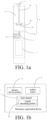
- FIG. 1a is a schematic structural diagram of an electronic atomization device according to the present disclosure
- FIG. 1b is a schematic block diagram of an electronic atomization device according to the present disclosure.
- the electronic atomization device includes an activation channel 1, an airflow sensor 2, and a mouthpiece 3.
- One end of the activation channel 1 is in communication with the mouthpiece 3 and the other end of the activation channel 1 is in communication with the airflow sensor 2, a liquid absorbing portion 21 is arranged on the section of the activation channel 1 close to the airflow sensor 2, and the liquid absorbing portion 21 is configured to absorb liquid flowing through the activation channel 1 through capillary force.
- the activation channel 1 is in communication with the mouthpiece 3 and the airflow sensor 2 and generates negative pressure during inhalation, and the airflow sensor 2 senses a change of air pressure and starts a heating function. In this way, the electronic atomization device starts to work.
- the electronic atomization device further includes a liquid storage tank 4, an atomization channel 5, an air inlet 6, and a power supply 7.
- the atomization channel 5 communicates the air inlet 6 with the mouthpiece 3, and the atomization channel 5 is in communication with the activation channel 1.
- the atomization channel 5 includes an atomization cavity 51, an atomization core 52 is arranged in the atomization cavity 51, the atomization core 52 is configured to atomize liquid from the liquid storage tank 4, and the liquid absorbing portion 21 is arranged between the atomization core 52 and the airflow sensor 2.
- the power supply 7 is configured to supply power to the atomization core 52, and the atomization core 52 works to atomize the liquid.
- the atomization channel 5 includes an air outlet channel 53, where the air outlet channel 53 penetrates the liquid storage tank 4, one end of the air outlet channel 53 is in communication with the mouthpiece 3, and the other end of the air outlet channel 53 is in communication with the atomization cavity 51.
- the air inlet 6 is in communication with the atomization cavity 51. Negative pressure is generated during inhalation, when external air enters the atomization cavity 51 from the air inlet 6, the airflow sensor 2 senses the change of the air pressure and starts the heating function, and then the external air carries the liquid atomized by the atomization core 52 through the air outlet channel 53 and reaches the mouthpiece 3 to be inhaled by a user.
- a part of the activation channel 1 is shared by the atomization cavity 51 and the air outlet channel 53.
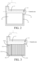
- FIG. 2 is a schematic structural diagram of a first embodiment of an activation channel 1 of an electronic atomization device according to the present disclosure.
- the activation channel 1 includes a first airway 11, a second airway 12, and an accommodating cavity 13 configured to receive a liquid absorbing element.
- One end of the first airway 11 is in communication with the airflow sensor 2, the other end of the first airway 11 is in communication with one end of the second airway 12, and the other end of the second airway 12 is in communication with the mouthpiece 3.
- the extending direction of the first airway 11 is perpendicular to the extending direction of the second airway 12.
- the accommodating cavity 13 is in communication with the first airway 11.
- the end of the first airway 11 in communication with the airflow sensor 2 is also in communication with the outside.
- the activation channel 1 Since the activation channel 1 is in fluid communication with the atomization channel 5, condensate generated by condensed atomized gas in the atomization channel 5 enters the activation channel 1. When liquid leaks from the electronic atomization device, the leaked liquid also enters the activation channel 1. The leaked liquid and the condensate entering the activation channel 1 contaminates the airflow sensor 2, and affects smoothness of the activation channel 1.
- a through hole 111 is provided on the side wall of the end for being in communication with the outside of the first airway 11, and is used as an interface to be in communication with the airflow sensor 2.
- the shape and size of the through hole 111 are not limited, and may be designed according to the size of the airflow sensor 2.
- a microphone is generally selected as the airflow sensor 2.
- Other elements may also be selected as the airflow sensor 2, as long as the elements can realize a function of starting the electronic atomization device, which is not limited herein.
- the liquid absorbing portion 21 is arranged in the accommodating cavity 13, and the liquid absorbing portion 21 includes a porous liquid storage element 211.
- the porous liquid storage element 211 is arranged in an entire space of the accommodating cavity 13.
- the porous liquid storage element 211 includes a liquid storage cotton or porous ceramic. The liquid diffuses in the porous liquid storage element 211 in the direction from the position close to the second airway 12 to the position away from the second airway 12.
- the porous liquid storage element 211 may be replaced after the porous liquid storage element 211 is full of the liquid or a liquid absorbing speed becomes slow, which can prevent liquid from being trapped in the activation channel 1 as much as possible, and prevent the liquid from soaking the airflow sensor 2, thereby improving the performance of the electronic atomization device.
- the porous liquid storage element 211 may fill part of or the entire accommodating cavity 13. Even after the porous liquid storage element 211 fills the entire accommodating cavity 13, the porous liquid storage element 211 is also arranged in the part of the first airway 11, and the porous liquid storage element 211 has a maximum liquid absorption capability.
- the liquid absorbing portion 21 includes a material that expands upon liquid absorption, the material fills only a part of the accommodating cavity 13.
- the extending direction of the first airway 11 may also be not perpendicular to the extending direction of the second airway 12, as long as a certain included angle between the extending direction of the first airway 11 and the extending direction of the second airway 12 is formed to meet a requirement.
- the second airway 12 is a closed tubular structure.
- the first airway 11 is also a tubular structure, but an opening is defined on the side wall where the first airway 11 is connected with the accommodating cavity 13. In this way, the accommodating cavity 13 is in communication with the first airway 11.
- FIG. 3 is a schematic structural diagram of a second embodiment of an activation channel 1 of an electronic atomization device according to the present disclosure.
- the liquid absorbing portion 21 includes a capillary liquid guiding structure 212.
- the capillary liquid guiding structure 212 includes a plurality of first fins 2121, and the plurality of first fins 2121 are arranged in parallel at intervals to form at least one first capillary groove 2122. That is, the at least one first capillary groove 2122 includes a plurality of first capillary grooves 2122 arranged side by side. It may be understood that, the capillary liquid guiding structure 212 includes at least two first fins 2121, that is, at least one first capillary groove 2122 is formed.
- the first capillary groove 2122 is configured to absorb and store the liquid flowing through the activation channel 1, so as to keep the smoothness of the activation channel 1 and prevent the liquid from soaking the airflow sensor 2.
- the widths of the plurality of first fins 2121 fall in the range from 0.6 mm to 1.0 mm, and the width of the first capillary groove 2122 falls in the range from 0.3 mm to 0.5 mm.
- An included angle between the extending direction of the plurality of first fins 2121 and the extending direction of the first airway 11 is greater than 30 degrees, and preferably, falls in the range from 60 degrees to 90 degrees, and the liquid may be absorbed by the first capillary groove 2122 smoothly. In this embodiment, the included angle between the extending direction of the plurality of first fins 2121 and the extending direction of the first airway 11 is 90 degrees.
- the distances from the ends of the plurality of first fins 2121 close to the first airway 11 to the central axis of the first airway 11 are equal and fall in the range from 0.9 mm to 1.5 mm.
- the distances from the ends of the plurality of first fins 2121 away from the first airway 11 to the central axis of the first airway 11 may be equal or may be not equal.
- the accommodating cavity 13 includes a first region 221 corresponding to the first airway 11 and a second region 222 corresponding to the second airway 12.
- the distance between one end of the first fin 2121 arranged in the first region 221 close to the first airway 11 and the central axis of the first airway 11 is defined as a first distance L1
- the distance between the one end of the first fin 2121 arranged in the second region 222 close to the first airway 11 and the central axis of the first airway 11 is defined as a second distance L2
- the first distance L1 is greater than second distance L2.
- a plurality of second distances L2 of the plurality of first fins 2121 arranged in the second region 222 may be equal and fall in the range from 0.3 mm to 0.5 mm; and a plurality of first distances L1 of the plurality of first fins 2121 arranged in the first region 221 are equal and fall in the range from 0.9 mm to 1.5 mm.
- the plurality of second distances L2 of the plurality of first fins 2121 arranged in the second region 222 may be not equal and decrease gradually in equal difference in the direction from the position away from the first region 221 to the position close to the first region 221, and the equal difference falls in the range from 0.3 mm to 0.5 mm; and the plurality of first distances L1 of the plurality of first fins 2121 arranged in the first region 221 are equal and fall in the range from 0.9 mm to 1.5 mm.
- FIG. 4 is a schematic structural diagram of a third embodiment of an activation channel 1 of an electronic atomization device according to the present disclosure.
- the structure of a start assembly of the third embodiment in the present disclosure is basically the same as that of the electronic atomization device of the second embodiment in the present disclosure, where a difference lies in that the liquid absorbing portion 21 includes a porous liquid storage element 211 and a capillary liquid guiding structure 212.
- the capillary liquid guiding structure 212 includes a plurality of first fins 2121.
- the accommodating cavity 13 includes a first space 22 close to the first airway 11 and a second space 23 away from the first airway 12.
- the plurality of first fins 2121 are arranged in the first space 22.
- the porous liquid storage element 211 is arranged in the second space 23, that is, the plurality of first fins 2121 are arranged between the porous liquid storage element 211 and the first airway 11.
- the plurality of first fins 2121 are arranged in parallel at intervals to form a first capillary groove 2122.
- the widths of the plurality of first fins 2121 fall in the range from 0.6 mm to 1.0 mm, and the width of the first capillary groove 2122 falls in the range from 0.3 mm to 0.5 mm.
- An included angle between the extending direction of the plurality of first fins 2121 and the extending direction of the first airway 11 is greater than 30 degrees, and preferably, falls in the range from 60 degrees to 90 degrees, and the liquid may flow through the first capillary groove 2122 into the second space 23 smoothly.
- the included angle between the extending direction of the plurality of first fins 2121 and the extending direction of the first airway 11 is 90 degrees.
- the distances from the ends of the plurality of first fins 2121 close to the first airway 11 to the central axis of the first airway 11 are equal and fall in the range from 0.9 mm to 1.5 mm.
- the distances from the ends of the plurality of first fins 2121 away from the first airway 11 to the central axis of the first airway 11 may be equal or may be not equal, as long as the ends of the plurality of first fins 2121 away from the first airway 11 are in contact with the porous liquid storage element 211.
- the first capillary groove 2122 is in communication with the first airway 11 and the second space 23, and liquid entering the activation channel 1 may flow into the second space 23 through the first capillary groove 2122, and be absorbed by the porous liquid storage element 211 in the second space 23, thereby keeping the smoothness of the activation channel 1, and preventing the liquid from soaking the airflow sensor 2.
- the liquid diffuses in the porous liquid storage element 211 in the direction from the position close to the second airway 12 to the position away from the second airway 12.
- the plurality of first fins 2121 are arranged in the accommodating cavity 13 to guide the liquid flowing into the activation channel 1, and the liquid is absorbed by the porous liquid storage element 211.
- the liquid flowing into the activation channel 1 is guided by the first capillary groove 2122 between the plurality of first fins 2121 to be absorbed by the porous liquid storage element 211, which does not affect the smoothness of the activation channel 1.
- the amount of the leaked liquid is large, the liquid flowing into the activation channel 1 is first guided to the porous liquid storage element 211 by the plurality of first fins 2121, and when the porous liquid storage element 211 does not have the ability to absorb the liquid, a liquid level in the second airway 12 is further raised.
- the through hole 111 in communication with the airflow sensor 2 is the last region that the liquid contacts, so as to protect the airflow sensor 2 to the greatest extent.
- the porous liquid storage element 211 may be replaced after the porous liquid storage element 211 is full of the liquid or a liquid absorbing speed becomes slow, which can prevent liquid from being trapped in the activation channel 1 as much as possible, and prevent the liquid from soaking the airflow sensor 2, thereby improving the performance of the electronic atomization device.
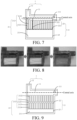
- FIG. 5 is an experimental phenomenon diagram of the third embodiment of an activation channel 1 of an electronic atomization device according to the present disclosure.
- the liquid can be guided, and the leaked liquid entering the activation channel 1 is absorbed by the porous liquid storage element 211, which protects the airflow sensor 2 to the greatest extent, and prevents the liquid from being trapped in the activation channel 1.
- the first capillary groove 2122 rising of liquid in the lower part and sinking of liquid in the upper part may form an air column.
- a sidewall surface of an opening of a test piece is attached to an acrylic plate, which is convenient for observing flowing of the liquid.
- FIG. 6 is a schematic structural diagram of a fourth embodiment of an activation channel 1 of an electronic atomization device according to the present disclosure.
- the structure of a start assembly of the fourth embodiment in the present disclosure is basically the same as that of the electronic atomization device of the third embodiment in the present disclosure, where a difference lies in a structure of the plurality of first fins 2121.
- the liquid absorbing portion 21 includes a porous liquid storage element 211 and a plurality of first fins 2121.
- the accommodating cavity 13 includes a first space 22 close to the first airway 11 and a second space 23 away from the first airway 12.
- the plurality of first fins 2121 are arranged in the first space 22.
- the porous liquid storage element 211 is arranged in the second space 23.
- the plurality of first fins 2121 are arranged in parallel at intervals to form a first capillary groove 2122.
- the widths of the plurality of first fins 2121 fall in the range from 0.6 mm to 1.0 mm, and the width of the first capillary groove 2122 falls in the range from 0.3 mm to 0.5 mm.
- the first capillary groove 2122 is in communication with the first airway 11 and the second space 23, and liquid entering the activation channel 1 may flow into the second space 23 through the first capillary groove 2122 and be absorbed by the porous liquid storage element 211 in the second space 23, thereby keeping the smoothness of the activation channel 1, and preventing the liquid from soaking the airflow sensor 2.
- the accommodating cavity 13 includes a first region 221 corresponding to the first airway 11 and a second region 222 corresponding to the second airway 12.
- the distance between one end of the first fin 2121 arranged in the first region 221 close to the first airway 11 and the central axis of the first airway 11 is defined as a first distance L1
- the distance between the one end of the first fin 2121 arranged in the second region 222 close to the first airway 11 and the central axis of first airway 11 is defined as a second distance L2.
- the first distance L1 is greater than the second distance L2. That is, the height of the first fin 2121 arranged in the second region 222 is greater than the height of the first fin 2121 arranged in the first region 221.
- a plurality of second distances L2 of the plurality of first fins 2121 arranged in the second region 222 are equal and fall in the range from 0.3 mm to 0.5 mm.
- a plurality of first distances L1 of the plurality of first fins 2121 arranged in the first region 221 are equal and fall in the range from 0.9 mm to 1.5 mm.
- the distances from the ends of the plurality of first fins 2121 away from the first airway 11 to the central axis of the first airway 11 may be equal or may be not equal, as long as the ends of the plurality of first fins 2121 away from the first airway 11 are in contact with the porous liquid storage element 211.
- FIG. 7 is a schematic structural diagram of another implementation of the fourth embodiment of an activation channel 1 of an electronic atomization device according to the present disclosure.
- the plurality of second distances L2 of the plurality of first fins 2121 arranged in the second region 222 decrease gradually in equal difference in the direction from the position away from the first region 221 to the position close to the first region 221, and the equal difference falls in the range from 0.3 mm to 0.5 mm; and the plurality of first distances L1 of the plurality of first fins 2121 arranged in the first region 221 are equal and fall in the range from 0.9 mm to 1.5 mm.
- the distances from the ends of the plurality of first fins 2121 away from the first airway 11 to the central axis of the first airway 11 may be equal or may be not equal, as long as the ends of the plurality of first fins 2121 away from the first airway 11 are in contact with the porous liquid storage element 211.
- FIG. 8 is an experimental phenomenon diagram of the another implementation of the fourth embodiment of an activation channel 1 of an electronic atomization device according to the present disclosure.
- the plurality of second distances L2 of the plurality of first fins 2121 in the second region 222 decrease gradually in equal difference in the direction from the position away from the first region 221 to the position close to the first region 221, and the porous liquid storage element 211 accounts for 1/2 of the volume of the accommodating cavity 13, which can both promote the liquid flowing and increase a liquid storage capacity, thereby protecting the airflow sensor 2 to the greatest extent and keeping the smoothness of the activation channel 1.
- a sidewall surface of an opening of a test piece is attached to an acrylic plate, which is convenient for observing flowing of the liquid.
- An included angle between the extending direction of the plurality of first fins 2121 and the extending direction of the first airway 11 falls in the range 60 degrees to 90 degrees, and the liquid may flow through the first capillary groove 2122 into the second space 23 smoothly. In some embodiments, the included angle between the extending direction of the plurality of first fins 2121 and the extending direction of the first airway 11 is 90 degrees.
- the plurality of first fins 2121 are arranged in the accommodating cavity 13 to guide the liquid flowing into the activation channel 1, and the liquid is absorbed by the porous liquid storage element 211.
- the accommodating cavity 13 is divided into a first region 221 corresponding to the first airway 11 and a second region 222 corresponding to the second airway 12, and the first distance L1 is set to be greater than the second distance L2. In this way, liquid entering the activation channel 1 through an interface of the second airway 12 in communication with the atomization channel 5 can enter the first capillary groove 2122 more smoothly.
- the plurality of second distances L2 of the plurality of first fins 2121 arranged in the second region 222 may decrease gradually in equal difference in the direction from the position away from the first region 221 to the position close to the first region 221.
- the liquid diffuses in the porous liquid storage element 211 in the direction from the position away from the first region 221 to the position close to the first region 221.
- the liquid flowing into the activation channel 1 is guided by the plurality of first fins 2121 to be absorbed by the porous liquid storage element 211, which does not affect the smoothness of the activation channel 1.
- the liquid flowing into the activation channel 1 is first guided to the porous liquid storage element 211 by the plurality of first fins 2121, and when the porous liquid storage element 211 does not have the ability to absorb the liquid, a liquid level in the second airway 12 is further raised.
- the through hole 111 in communication with the airflow sensor 2 is the last region that the liquid contacts, so as to protect the airflow sensor 2 to the greatest extent.
- the porous liquid storage element 211 may be replaced after the porous liquid storage element 211 is full of the liquid or a liquid absorbing speed becomes slow, which can prevent liquid from being trapped in the activation channel 1 as much as possible, and prevent the liquid from soaking the airflow sensor 2, thereby improving the performance of the electronic atomization device.
- the second space 23 accounts for at least 1/2 of the volume of the accommodating cavity 13. In other implementations, the second space 23 accounts for 1/3 of the volume of the accommodating cavity 13. A larger number of accommodating cavities 13 arranged in the porous liquid storage element 211 indicates greater liquid absorbing and storage capabilities. By setting the second space 23 to account for at least 1/2 of the volume of the accommodating cavity 13, both the liquid flowing may be prompted and a liquid storage capacity may be increased, thereby protecting the airflow sensor 2 to the greatest extent and keeping the smoothness of the activation channel 1.
- FIG. 9 is a schematic structural diagram of a fifth embodiment of an activation channel 1 of an electronic atomization device according to the present disclosure.
- the structure of a start assembly of the fifth embodiment in the present disclosure is basically the same as that of the electronic atomization device of the third embodiment in the present disclosure, where a difference lies in that the liquid absorbing portion 21 includes a porous liquid storage element 211, a plurality of first fins 2121, and a plurality of second fins 2123.
- the plurality of first fins 2121 and the plurality of second fins 2123 are arranged in the first space 22.
- the porous liquid storage element 211 is arranged in the second space 23.
- the second space 23 accounts for 1/3 of the volume of the accommodating cavity 13.
- the plurality of second fins 2123 are arranged between the plurality of first fins 2121 and the second space 23; the plurality of first fins 2121 are arranged in parallel at intervals to form a first capillary groove 2122; the plurality of second fin 2123 are arranged in parallel at intervals to form a second capillary groove 2124; the first capillary groove 2122 is in communication with the second capillary groove 2124; and a third capillary groove 2125 is formed between the plurality of first fins 2121 and the plurality of second fins 2124.
- the extending direction of the first capillary groove 2122 is the same as the extending direction of the second capillary groove 2124, and the extending direction of the third capillary groove 2125 is perpendicular to the extending direction of the second capillary groove 2124.
- the plurality of first fins 2121 and the plurality of second fins 2123 may also be arranged in a one-to-one correspondence or in a staggered manner (referring to FIG.
- FIG. 10 which is a schematic partial view of another implementation of a plurality of first fins 2121 and a plurality of second fins 2124 in the fifth embodiment of an activation channel 1 of an electronic atomization device according to the present disclosure), as long as the first capillary groove 2122 is in communication with the second capillary groove 2124.
- the width of the first fin 2121 falls in the range 0.6 mm to 1.0 mm, and the width of the first capillary groove 2122 falls in the range 0.3 mm to 0.5 mm; the width of the second fin 2123 falls in the range 0.6 mm to 1.0 mm, and the width of the second capillary groove 2124 falls in the range 0.3 mm to 0.5 mm; and the width of the third capillary groove 2125 falls in the range 0.3 mm to 0.5 mm.
- the first capillary groove 2122 and the second capillary groove 2124 are in communication with the first airway 11 and the second space 23, and the liquid entering the activation channel 1 may flow into the second space 23 through the first capillary groove 2122 and the second capillary groove 2124, and be absorbed by the porous liquid storage element 211 in the second space 23, thereby keeping the smoothness of the activation channel 1, and preventing the liquid from soaking the airflow sensor 2.
- the distances from the ends of the plurality of first fins 2121 close to the first airway 11 to the central axis of the first airway 11 are equal and fall in the range from 0.9 mm to 1.5 mm.
- the distances from the ends of the plurality of first fins 2121 away from the first airway 11 to the central axis of the first airway 11 are equal.
- the distances from the ends of the plurality of second fins 2123 close to the first airway 11 to the central axis of the first airway 11 are equal.
- the distances from the ends of the plurality of second fins 2123 away from the first airway 11 to the central axis of the first airway 11 may be equal or may be not equal, as long as the ends of the plurality of second fins 2123 away from the first airway 11 are in contact with the porous liquid storage element 211.
- FIG. 11 is an experimental phenomenon diagram of the activation channel 1 of the electronic atomization device provided in FIG. 9 .
- the plurality of first fins 2121 and the plurality of second fins 2123 are arranged in a one-to-one correspondence, and the third capillary groove 2125 is formed between the plurality of first fins 2121 and the plurality of second fins 2123, which can prevent an air column from being formed in the first capillary groove 2122 or the second capillary groove 2124.
- the airflow sensor 2 is protected and the smoothness the activation channel 1 is kept.
- a sidewall surface of an opening of a test piece is attached to an acrylic plate, which is convenient for observing flowing of the liquid.
- the accommodating cavity 13 includes a first region 221 corresponding to the first airway 11 and a second region 222 corresponding to the second airway 12.
- the distance between one end of the first fin 2121 arranged in the first region 221 close to the first airway 11 and the central axis of the first airway 11 is defined as a first distance L1
- the distance between the one end of the first fin 2121 arranged in the second region 222 close to the first airway 11 and the central axis of the first airway 11 is defined as a second distance L2
- the first distance L1 is greater than second distance L2.
- FIG. 12 is a schematic structural diagram of an implementation of the fifth embodiment of an activation channel 1 of an electronic atomization device according to the present disclosure.
- the plurality of second distances L2 of the plurality of first fins 2121 arranged in the second region 222 may be equal and fall in the range from 0.3 mm to 0.5 mm; and the plurality of first distances L1 of the plurality of first fins 2121 arranged in the first region 221 are equal and fall in the range from 0.9 mm to 1.5 mm.
- FIG. 13 is an experimental phenomenon diagram of the activation channel 1 of the electronic atomization device provided in FIG. 12 .
- the plurality of second distances L2 of the plurality of first fins 2121 arranged in the second region 222 are equal, and the plurality of first distances L1 of the plurality of first fins 2121 arranged in the first region 221 are equal.
- the plurality of first fins between the first region 221 and the second region 222 form a gradient, and the liquid may enter the first capillary groove 2122 and the second capillary groove 2124 in the first region 221 more smoothly.
- the airflow sensor 2 is protected and the smoothness the activation channel 1 is kept.
- a sidewall surface of an opening of a test piece is attached to an acrylic plate, which is convenient for observing flowing of the liquid.
- FIG. 14 is a schematic structural diagram of an implementation of the fifth embodiment of an activation channel 1 of an electronic atomization device according to the present disclosure.
- the plurality of second distances L2 of the plurality of first fins 2121 arranged in the second region 222 may be not equal and decrease gradually in equal difference in the direction from the position away from the first region 221 to the position close to the first region 221, and the equal difference falls in the range from 0.3 mm to 0.5 mm; and the plurality of first distances L1 of the plurality of first fins 2121 arranged in the first region 221 are equal and fall in the range from 0.9 mm to 1.5 mm.
- FIG. 15 is an experimental phenomenon diagram of the activation channel 1 of the electronic atomization device provided in FIG. 14 .
- the plurality of second distances L2 of the plurality of first fins 2121 arranged in the second region 222 decrease gradually in equal difference in the direction from the position away from the first region 221 to the position close to the first region 221, which can prevent formation of capillary action between the plurality of first fins 2121 in the second region 222 from affecting the liquid entering the first capillary groove 2122 formed by the plurality of first fins 2121 in the first region 221.
- a sidewall surface of an opening of a test piece is attached to an acrylic plate, which is convenient for observing flowing of the liquid.
- the plurality of first fins 2121 and the plurality of second fins 2123 are arranged in a one-to-one correspondence.
- An included angle between the extending directions of the plurality of first fins 2121 and the plurality of second fins 2123 and the extending direction of the first airway 11 falls in the range from 60 degrees to 90 degrees, and the liquid may flow through the first capillary groove 2122 and the second capillary groove 2124 into the second space 23 smoothly.
- the included angle between the extending directions of the plurality of first fins 2121 and the plurality of second fins 2123 and the extending direction of the first airway 11 is 90 degrees.
- the plurality of first fins 2121 and the plurality of second fins 2123 are arranged in the accommodating cavity 13 to guide the liquid flowing into the activation channel 1, and the liquid is absorbed by the porous liquid storage element 211.
- the accommodating cavity 13 is divided into a first region 221 corresponding to the first airway 11 and a second region 222 corresponding to the second airway 12, and the first distance L1 is set to be greater than the second distance L2. in this way, liquid entering the activation channel 1 through an interface of the second airway 12 in communication with the atomization channel 5 can enter the first capillary groove 2122 and the second capillary groove 2124 more smoothly.
- the plurality of second distances L2 of the plurality of first fins 2121 arranged in the second region 222 may decrease gradually in equal difference in the direction from a position away from the first region 221 to a position close to the first region 221.
- the third capillary groove 2125 is formed between the plurality of first fins 2121 and the plurality of second fins 2123, thereby preventing the liquid from forming an air column in the first capillary groove 2122 or the second capillary groove 2124 to affect the liquid absorbed by the porous liquid storage element 211.
- the liquid diffuses in the porous liquid storage element 211 in the direction from the position away from the first region 221 to the position close to the first region 221.
- the liquid flowing into the activation channel 1 is guided by the plurality of first fins 2121 and the plurality of second fins 2123 to be absorbed by the porous liquid storage element 211, which does not affect the smoothness of the activation channel 1.
- the liquid flowing into the activation channel 1 is first guided to the porous liquid storage element 211 by the plurality of first fins 2121 and the plurality of second fins 2123, and when the porous liquid storage element 211 does not have the ability to absorb the liquid, a liquid level in the second airway 12 is further raised.
- the through hole 111 in communication with the airflow sensor 2 is the last region that the liquid contacts, so as to protect the airflow sensor 2 to the greatest extent.
- the porous liquid storage element 211 may be replaced after the porous liquid storage element 211 is full of the liquid or a liquid absorbing speed becomes slow, which can prevent liquid from being trapped in the activation channel 1 as much as possible, and prevent the liquid from soaking the airflow sensor 2, thereby improving the performance of the electronic atomization device.
- the capillary force of the capillary groove away from the airflow sensor 2 is greater than the capillary force of the capillary groove close to the airflow sensor 2. In this way, more leaked liquid may be stored in places away from the airflow sensor 2.
- the capillary liquid guiding structure 212 may include the plurality of first fins 2121 and/or the plurality of second fins 2123, and both the plurality of first fins 2121 and the plurality of second fins 2123 include metal or ceramic.
- the capillary liquid guiding structure 212 includes porous ceramic, and the porous liquid storage element 211 is made of the porous ceramic, the capillary force of the capillary liquid guiding structure 212 is different from the capillary force of the porous liquid storage element 211.
- the liquid absorbing portion 21 is arranged in the activation channel 1, and the liquid absorbing portion 21 absorbs the liquid flowing through the activation channel 1 through the capillary force, thereby preventing the leaked liquid from soaking the airflow sensor 2, preventing failure of the airflow sensor, and ensuring the smoothness of the activation channel 1.
Landscapes
- Fire-Detection Mechanisms (AREA)
- Investigating Or Analyzing Materials By The Use Of Electric Means (AREA)
Abstract
Description
- The present disclosure relates to the field of atomizers, and in particular, to an electronic atomization device.
- An electronic atomization device includes an atomization assembly and a power supply assembly, and annular silica gel is arranged between the atomization assembly and the power supply assembly for sealing. During use of the electronic atomization device, condensate is generated; and liquid leakage may occur due to improper operations or other reasons. Paths of the liquid leakage include an activation channel and a position sealed by the annular silica gel. When sealing of the annular silica gel fails, liquid may leak from an atomizer to the inside of a battery, causing failures of a microphone and a circuit board. Generally, the electronic atomization device is started with the microphone, and the failure of the microphone affects use of the electronic atomization device.
- In view of this, the present disclosure provides an electronic atomization device, to resolve the problems that leaked liquid causes failure of an airflow sensor and the leaked liquid is trapped in an activation channel in the related art.
- To resolve the foregoing technical problems, a first technical solution provided in the present disclosure is as follows: an electronic atomization device is provided, including a mouthpiece, an airflow sensor, and an activation channel, communicating the mouthpiece and the airflow sensor, a liquid absorbing portion is arranged on the section of the activation channel close to the airflow sensor, and the liquid absorbing portion is configured to absorb liquid flowing through the activation channel through capillary force.
- In some embodiments, the liquid absorbing portion includes a capillary liquid guiding structure including at least one capillary groove, and the capillary groove is configured to absorb the liquid flowing through the activation channel.
- In some embodiments, the at least one capillary groove includes a plurality of capillary grooves are provided, and the plurality of capillary grooves are arranged side by side.
- In some embodiments, the capillary force of the capillary groove away from the airflow sensor is greater than the capillary force of the capillary groove close to the airflow sensor.
- In some embodiments, the liquid absorbing portion includes a capillary liquid guiding structure and a porous liquid storage element, and the capillary liquid guiding structure communicates the activation channel and the porous liquid storage element to guide the liquid flowing through the activation channel to the porous liquid storage element.
- In some embodiments, the capillary liquid guiding structure is a structure including a plurality of capillary grooves arranged side by side.
- In some embodiments, the porous liquid storage element includes a liquid storage cotton or porous ceramic.
- In some embodiments, the capillary force of the capillary groove away from the airflow sensor is greater than the capillary force of the capillary groove close to the airflow sensor.
- In some embodiments, the capillary liquid guiding structure includes a plurality of first fins, and the plurality of first fins are arranged in parallel at intervals to form at least one first capillary groove.
- In some embodiments, the activation channel includes a first airway and a second airway; one end of the first airway is in communication with the airflow sensor, the other end of the first airway is in communication with one end of the second airway, and the other end of the second airway is in communication with the mouthpiece; and the distances from the ends of the plurality of first fins close to the first airway to the central axis of the first airway are equal and fall in the range from 0.9 mm to 1.5 mm.
- In some embodiments, the region corresponding to the first airway is defined as a first region, and the region corresponding to the second airway is defined as a second region; and the distance between one end of the first fin arranged in the first region close to the first airway and a central axis of the first airway is defined as a first distance, the distance between the one end of the first fin arranged in the second region close to the first airway and the central axis of the first airway is defined as a second distance, and the first distance is greater than the second distance.
- In some embodiments, a plurality of second distances of the plurality of first fins arranged in the second region are equal and fall in the range from 0.3 mm to 0.5 mm; and a plurality of first distances of the plurality of first fins arranged in the first region are equal and fall in the range from 0.9 mm to 1.5 mm.
- In some embodiments, a plurality of second distances of the plurality of first fins arranged in the second region decrease gradually in equal difference in the direction from the position away from the first region to the position close to the first region, and the equal difference falls in the range from 0.3 mm to 0.5 mm; and a plurality of first distances of the plurality of first fins arranged in the first region are equal and fall in the range from 0.9 mm to 1.5 mm.
- In some embodiments, the capillary liquid guiding structure further includes a plurality of second fins, and the plurality of second fins are arranged on one side of the plurality of first fins away from the first airway; the plurality of second fins are arranged in parallel at intervals to form at least one second capillary groove in communication with the first capillary groove; and a third capillary groove is formed between the plurality of first fins and the plurality of second fins.
- In some embodiments, an included angle between the extending directions of the plurality of first fins and the plurality of second fins and the extending direction of the first airway falls in the range from 60 degrees to 90 degrees; and the at least one first capillary groove and the at least one second capillary groove are arranged in a one-to-one correspondence or in a staggered manner.
- In some embodiments, the width of the first fin falls in the from 0.6 mm to 1.0 mm, and the width of the first capillary groove falls in the range from 0.3 mm to 0.5 mm; the width of the second fin falls in the range from 0.6 mm to 1.0 mm, and the width of the second capillary groove falls in the range from 0.3 mm to 0.5 mm; and the width of the third capillary groove falls in the range from 0.3 mm to 0.5 mm.
- In some embodiments, both the first fin and the second fin include metal or porous ceramic.
- In some embodiments, the electronic atomization device further includes an air inlet and an atomization channel, where The atomization channel is in communication with the air inlet and the mouthpiece, the atomization channel is arranged with an atomization core, and the atomization channel is in fluid communication with the activation channel.
- In some embodiments, the electronic atomization device includes a liquid storage tank, the atomization channel includes an atomization cavity with the atomization core being arranged therein, the atomization core is configured to atomize liquid from the liquid storage tank, and the liquid absorbing portion is arranged between the atomization core and the airflow sensor.
- Beneficial effects of the present disclosure are as follows: Compared with the related art, in the present disclosure, the liquid absorbing portion is arranged in the activation channel, and the liquid absorbing portion absorbs the liquid flowing through the activation channel through the capillary force, thereby preventing the leaked liquid from soaking the airflow sensor, preventing failure of the airflow sensor, and ensuring smoothness of the activation channel.
-
-
FIG. 1a is a schematic structural diagram of an electronic atomization device according to the present disclosure. -
FIG. 1b is a schematic block diagram of an electronic atomization device according to the present disclosure. -
FIG. 2 is a schematic structural diagram of a first embodiment of an activation channel of an electronic atomization device according to the present disclosure. -
FIG. 3 is a schematic structural diagram of a second embodiment of an activation channel of an electronic atomization device according to the present disclosure. -
FIG. 4 is a schematic structural diagram of a third embodiment of an activation channel of an electronic atomization device according to the present disclosure. -
FIG. 5 is an experimental phenomenon diagram of the third embodiment of an activation channel of an electronic atomization device according to the present disclosure. -
FIG. 6 is a schematic structural diagram of a fourth embodiment of an activation channel of an electronic atomization device according to the present disclosure. -
FIG. 7 is a schematic structural diagram of another implementation of the fourth embodiment of an activation channel of an electronic atomization device according to the present disclosure. -
FIG. 8 is an experimental phenomenon diagram of the another implementation of the fourth embodiment of an activation channel of an electronic atomization device according to the present disclosure. -
FIG. 9 is a schematic structural diagram of a fifth embodiment of an activation channel of an electronic atomization device according to the present disclosure. -
FIG. 10 is a schematic partial view of another implementation of a plurality of first fins and a plurality of second fins in the fifth embodiment of an activation channel of an electronic atomization device according to the present disclosure. -
FIG. 11 is an experimental phenomenon diagram of the activation channel of the electronic atomization device provided inFIG. 9 . -
FIG. 12 is a schematic structural diagram of an implementation of the fifth embodiment of an activation channel of an electronic atomization device according to the present disclosure. -
FIG. 13 is an experimental phenomenon diagram of the activation channel of the electronic atomization device provided inFIG. 12 . -
FIG. 14 is a schematic structural diagram of another implementation of the fifth embodiment of an activation channel of an electronic atomization device according to the present disclosure. -
FIG. 15 is an experimental phenomenon diagram of the activation channel of the electronic atomization device provided inFIG. 14 . - the present disclosure is further described in detail below with reference to the accompanying drawings and embodiments.
- Referring to
FIG. 1a and FIG. 1b, FIG. 1a is a schematic structural diagram of an electronic atomization device according to the present disclosure; andFIG. 1b is a schematic block diagram of an electronic atomization device according to the present disclosure. - The electronic atomization device includes an
activation channel 1, anairflow sensor 2, and amouthpiece 3. One end of theactivation channel 1 is in communication with themouthpiece 3 and the other end of theactivation channel 1 is in communication with theairflow sensor 2, a liquid absorbingportion 21 is arranged on the section of theactivation channel 1 close to theairflow sensor 2, and theliquid absorbing portion 21 is configured to absorb liquid flowing through theactivation channel 1 through capillary force. Theactivation channel 1 is in communication with themouthpiece 3 and theairflow sensor 2 and generates negative pressure during inhalation, and theairflow sensor 2 senses a change of air pressure and starts a heating function. In this way, the electronic atomization device starts to work. - The electronic atomization device further includes a
liquid storage tank 4, anatomization channel 5, an air inlet 6, and apower supply 7. Theatomization channel 5 communicates the air inlet 6 with themouthpiece 3, and theatomization channel 5 is in communication with theactivation channel 1. Theatomization channel 5 includes anatomization cavity 51, anatomization core 52 is arranged in theatomization cavity 51, theatomization core 52 is configured to atomize liquid from theliquid storage tank 4, and the liquid absorbingportion 21 is arranged between theatomization core 52 and theairflow sensor 2. Thepower supply 7 is configured to supply power to theatomization core 52, and theatomization core 52 works to atomize the liquid. - The
atomization channel 5 includes anair outlet channel 53, where theair outlet channel 53 penetrates theliquid storage tank 4, one end of theair outlet channel 53 is in communication with themouthpiece 3, and the other end of theair outlet channel 53 is in communication with theatomization cavity 51. The air inlet 6 is in communication with theatomization cavity 51. Negative pressure is generated during inhalation, when external air enters theatomization cavity 51 from the air inlet 6, theairflow sensor 2 senses the change of the air pressure and starts the heating function, and then the external air carries the liquid atomized by theatomization core 52 through theair outlet channel 53 and reaches themouthpiece 3 to be inhaled by a user. - A part of the
activation channel 1 is shared by theatomization cavity 51 and theair outlet channel 53. - As shown in
FIG. 2, FIG. 2 is a schematic structural diagram of a first embodiment of anactivation channel 1 of an electronic atomization device according to the present disclosure. - The
activation channel 1 includes afirst airway 11, asecond airway 12, and anaccommodating cavity 13 configured to receive a liquid absorbing element. One end of thefirst airway 11 is in communication with theairflow sensor 2, the other end of thefirst airway 11 is in communication with one end of thesecond airway 12, and the other end of thesecond airway 12 is in communication with themouthpiece 3. The extending direction of thefirst airway 11 is perpendicular to the extending direction of thesecond airway 12. Theaccommodating cavity 13 is in communication with thefirst airway 11. In addition, the end of thefirst airway 11 in communication with theairflow sensor 2 is also in communication with the outside. - Since the
activation channel 1 is in fluid communication with theatomization channel 5, condensate generated by condensed atomized gas in theatomization channel 5 enters theactivation channel 1. When liquid leaks from the electronic atomization device, the leaked liquid also enters theactivation channel 1. The leaked liquid and the condensate entering theactivation channel 1 contaminates theairflow sensor 2, and affects smoothness of theactivation channel 1. - A through
hole 111 is provided on the side wall of the end for being in communication with the outside of thefirst airway 11, and is used as an interface to be in communication with theairflow sensor 2. The shape and size of the throughhole 111 are not limited, and may be designed according to the size of theairflow sensor 2. A microphone is generally selected as theairflow sensor 2. Other elements may also be selected as theairflow sensor 2, as long as the elements can realize a function of starting the electronic atomization device, which is not limited herein. - In the first embodiment, the
liquid absorbing portion 21 is arranged in theaccommodating cavity 13, and theliquid absorbing portion 21 includes a porousliquid storage element 211. The porousliquid storage element 211 is arranged in an entire space of theaccommodating cavity 13. The porousliquid storage element 211 includes a liquid storage cotton or porous ceramic. The liquid diffuses in the porousliquid storage element 211 in the direction from the position close to thesecond airway 12 to the position away from thesecond airway 12. During use, the porousliquid storage element 211 may be replaced after the porousliquid storage element 211 is full of the liquid or a liquid absorbing speed becomes slow, which can prevent liquid from being trapped in theactivation channel 1 as much as possible, and prevent the liquid from soaking theairflow sensor 2, thereby improving the performance of the electronic atomization device. - It may be understood that, the porous
liquid storage element 211 may fill part of or the entire accommodatingcavity 13. Even after the porousliquid storage element 211 fills the entire accommodatingcavity 13, the porousliquid storage element 211 is also arranged in the part of thefirst airway 11, and the porousliquid storage element 211 has a maximum liquid absorption capability. When theliquid absorbing portion 21 includes a material that expands upon liquid absorption, the material fills only a part of theaccommodating cavity 13. - It may be understood that, the extending direction of the
first airway 11 may also be not perpendicular to the extending direction of thesecond airway 12, as long as a certain included angle between the extending direction of thefirst airway 11 and the extending direction of thesecond airway 12 is formed to meet a requirement. Thesecond airway 12 is a closed tubular structure. Thefirst airway 11 is also a tubular structure, but an opening is defined on the side wall where thefirst airway 11 is connected with theaccommodating cavity 13. In this way, theaccommodating cavity 13 is in communication with thefirst airway 11. - As shown in
FIG. 3, FIG. 3 is a schematic structural diagram of a second embodiment of anactivation channel 1 of an electronic atomization device according to the present disclosure. - In the second embodiment, the
liquid absorbing portion 21 includes a capillaryliquid guiding structure 212. The capillaryliquid guiding structure 212 includes a plurality offirst fins 2121, and the plurality offirst fins 2121 are arranged in parallel at intervals to form at least onefirst capillary groove 2122. That is, the at least onefirst capillary groove 2122 includes a plurality of firstcapillary grooves 2122 arranged side by side. It may be understood that, the capillaryliquid guiding structure 212 includes at least twofirst fins 2121, that is, at least onefirst capillary groove 2122 is formed. Thefirst capillary groove 2122 is configured to absorb and store the liquid flowing through theactivation channel 1, so as to keep the smoothness of theactivation channel 1 and prevent the liquid from soaking theairflow sensor 2. - The widths of the plurality of
first fins 2121 fall in the range from 0.6 mm to 1.0 mm, and the width of thefirst capillary groove 2122 falls in the range from 0.3 mm to 0.5 mm. An included angle between the extending direction of the plurality offirst fins 2121 and the extending direction of thefirst airway 11 is greater than 30 degrees, and preferably, falls in the range from 60 degrees to 90 degrees, and the liquid may be absorbed by thefirst capillary groove 2122 smoothly. In this embodiment, the included angle between the extending direction of the plurality offirst fins 2121 and the extending direction of thefirst airway 11 is 90 degrees. - In this embodiment, the distances from the ends of the plurality of
first fins 2121 close to thefirst airway 11 to the central axis of thefirst airway 11 are equal and fall in the range from 0.9 mm to 1.5 mm. The distances from the ends of the plurality offirst fins 2121 away from thefirst airway 11 to the central axis of thefirst airway 11 may be equal or may be not equal. - In other implementations, the
accommodating cavity 13 includes afirst region 221 corresponding to thefirst airway 11 and asecond region 222 corresponding to thesecond airway 12. The distance between one end of thefirst fin 2121 arranged in thefirst region 221 close to thefirst airway 11 and the central axis of thefirst airway 11 is defined as a first distance L1, the distance between the one end of thefirst fin 2121 arranged in thesecond region 222 close to thefirst airway 11 and the central axis of thefirst airway 11 is defined as a second distance L2, and the first distance L1 is greater than second distance L2. - In some embodiments, a plurality of second distances L2 of the plurality of
first fins 2121 arranged in thesecond region 222 may be equal and fall in the range from 0.3 mm to 0.5 mm; and a plurality of first distances L1 of the plurality offirst fins 2121 arranged in thefirst region 221 are equal and fall in the range from 0.9 mm to 1.5 mm. - In another implementation, the plurality of second distances L2 of the plurality of
first fins 2121 arranged in thesecond region 222 may be not equal and decrease gradually in equal difference in the direction from the position away from thefirst region 221 to the position close to thefirst region 221, and the equal difference falls in the range from 0.3 mm to 0.5 mm; and the plurality of first distances L1 of the plurality offirst fins 2121 arranged in thefirst region 221 are equal and fall in the range from 0.9 mm to 1.5 mm. - As shown in
FIG. 4, FIG. 4 is a schematic structural diagram of a third embodiment of anactivation channel 1 of an electronic atomization device according to the present disclosure. - The structure of a start assembly of the third embodiment in the present disclosure is basically the same as that of the electronic atomization device of the second embodiment in the present disclosure, where a difference lies in that the
liquid absorbing portion 21 includes a porousliquid storage element 211 and a capillaryliquid guiding structure 212. The capillaryliquid guiding structure 212 includes a plurality offirst fins 2121. In some embodiments, theaccommodating cavity 13 includes afirst space 22 close to thefirst airway 11 and asecond space 23 away from thefirst airway 12. The plurality offirst fins 2121 are arranged in thefirst space 22. The porousliquid storage element 211 is arranged in thesecond space 23, that is, the plurality offirst fins 2121 are arranged between the porousliquid storage element 211 and thefirst airway 11. The plurality offirst fins 2121 are arranged in parallel at intervals to form afirst capillary groove 2122. The widths of the plurality offirst fins 2121 fall in the range from 0.6 mm to 1.0 mm, and the width of thefirst capillary groove 2122 falls in the range from 0.3 mm to 0.5 mm. An included angle between the extending direction of the plurality offirst fins 2121 and the extending direction of thefirst airway 11 is greater than 30 degrees, and preferably, falls in the range from 60 degrees to 90 degrees, and the liquid may flow through thefirst capillary groove 2122 into thesecond space 23 smoothly. In this embodiment, the included angle between the extending direction of the plurality offirst fins 2121 and the extending direction of thefirst airway 11 is 90 degrees. - In this embodiment, the distances from the ends of the plurality of
first fins 2121 close to thefirst airway 11 to the central axis of thefirst airway 11 are equal and fall in the range from 0.9 mm to 1.5 mm. The distances from the ends of the plurality offirst fins 2121 away from thefirst airway 11 to the central axis of thefirst airway 11 may be equal or may be not equal, as long as the ends of the plurality offirst fins 2121 away from thefirst airway 11 are in contact with the porousliquid storage element 211. - The
first capillary groove 2122 is in communication with thefirst airway 11 and thesecond space 23, and liquid entering theactivation channel 1 may flow into thesecond space 23 through thefirst capillary groove 2122, and be absorbed by the porousliquid storage element 211 in thesecond space 23, thereby keeping the smoothness of theactivation channel 1, and preventing the liquid from soaking theairflow sensor 2. The liquid diffuses in the porousliquid storage element 211 in the direction from the position close to thesecond airway 12 to the position away from thesecond airway 12. - The plurality of
first fins 2121 are arranged in theaccommodating cavity 13 to guide the liquid flowing into theactivation channel 1, and the liquid is absorbed by the porousliquid storage element 211. When an amount of the leaked liquid is small, the liquid flowing into theactivation channel 1 is guided by thefirst capillary groove 2122 between the plurality offirst fins 2121 to be absorbed by the porousliquid storage element 211, which does not affect the smoothness of theactivation channel 1. When the amount of the leaked liquid is large, the liquid flowing into theactivation channel 1 is first guided to the porousliquid storage element 211 by the plurality offirst fins 2121, and when the porousliquid storage element 211 does not have the ability to absorb the liquid, a liquid level in thesecond airway 12 is further raised. In this way, the throughhole 111 in communication with theairflow sensor 2 is the last region that the liquid contacts, so as to protect theairflow sensor 2 to the greatest extent. During use, the porousliquid storage element 211 may be replaced after the porousliquid storage element 211 is full of the liquid or a liquid absorbing speed becomes slow, which can prevent liquid from being trapped in theactivation channel 1 as much as possible, and prevent the liquid from soaking theairflow sensor 2, thereby improving the performance of the electronic atomization device. - As shown in
FIG. 5, FIG. 5 is an experimental phenomenon diagram of the third embodiment of anactivation channel 1 of an electronic atomization device according to the present disclosure. - As shown in
FIG. 5 , it may be seen that by arranging the plurality offirst fins 2121 and the porousliquid storage element 211, the liquid can be guided, and the leaked liquid entering theactivation channel 1 is absorbed by the porousliquid storage element 211, which protects theairflow sensor 2 to the greatest extent, and prevents the liquid from being trapped in theactivation channel 1. However, in thefirst capillary groove 2122, rising of liquid in the lower part and sinking of liquid in the upper part may form an air column. In an experiment, a sidewall surface of an opening of a test piece is attached to an acrylic plate, which is convenient for observing flowing of the liquid. - As shown in
FIG. 6, FIG. 6 is a schematic structural diagram of a fourth embodiment of anactivation channel 1 of an electronic atomization device according to the present disclosure. - The structure of a start assembly of the fourth embodiment in the present disclosure is basically the same as that of the electronic atomization device of the third embodiment in the present disclosure, where a difference lies in a structure of the plurality of
first fins 2121. In the fourth embodiment, theliquid absorbing portion 21 includes a porousliquid storage element 211 and a plurality offirst fins 2121. theaccommodating cavity 13 includes afirst space 22 close to thefirst airway 11 and asecond space 23 away from thefirst airway 12. The plurality offirst fins 2121 are arranged in thefirst space 22. The porousliquid storage element 211 is arranged in thesecond space 23. The plurality offirst fins 2121 are arranged in parallel at intervals to form afirst capillary groove 2122. The widths of the plurality offirst fins 2121 fall in the range from 0.6 mm to 1.0 mm, and the width of thefirst capillary groove 2122 falls in the range from 0.3 mm to 0.5 mm. - The
first capillary groove 2122 is in communication with thefirst airway 11 and thesecond space 23, and liquid entering theactivation channel 1 may flow into thesecond space 23 through thefirst capillary groove 2122 and be absorbed by the porousliquid storage element 211 in thesecond space 23, thereby keeping the smoothness of theactivation channel 1, and preventing the liquid from soaking theairflow sensor 2. - In this embodiment, the
accommodating cavity 13 includes afirst region 221 corresponding to thefirst airway 11 and asecond region 222 corresponding to thesecond airway 12. The distance between one end of thefirst fin 2121 arranged in thefirst region 221 close to thefirst airway 11 and the central axis of thefirst airway 11 is defined as a first distance L1, and the distance between the one end of thefirst fin 2121 arranged in thesecond region 222 close to thefirst airway 11 and the central axis offirst airway 11 is defined as a second distance L2. The first distance L1 is greater than the second distance L2. That is, the height of thefirst fin 2121 arranged in thesecond region 222 is greater than the height of thefirst fin 2121 arranged in thefirst region 221. - In a specific implementation, a plurality of second distances L2 of the plurality of
first fins 2121 arranged in thesecond region 222 are equal and fall in the range from 0.3 mm to 0.5 mm. A plurality of first distances L1 of the plurality offirst fins 2121 arranged in thefirst region 221 are equal and fall in the range from 0.9 mm to 1.5 mm. The distances from the ends of the plurality offirst fins 2121 away from thefirst airway 11 to the central axis of thefirst airway 11 may be equal or may be not equal, as long as the ends of the plurality offirst fins 2121 away from thefirst airway 11 are in contact with the porousliquid storage element 211. - As shown in
FIG. 7, FIG. 7 is a schematic structural diagram of another implementation of the fourth embodiment of anactivation channel 1 of an electronic atomization device according to the present disclosure. - In another implementation, the plurality of second distances L2 of the plurality of
first fins 2121 arranged in thesecond region 222 decrease gradually in equal difference in the direction from the position away from thefirst region 221 to the position close to thefirst region 221, and the equal difference falls in the range from 0.3 mm to 0.5 mm; and the plurality of first distances L1 of the plurality offirst fins 2121 arranged in thefirst region 221 are equal and fall in the range from 0.9 mm to 1.5 mm. The distances from the ends of the plurality offirst fins 2121 away from thefirst airway 11 to the central axis of thefirst airway 11 may be equal or may be not equal, as long as the ends of the plurality offirst fins 2121 away from thefirst airway 11 are in contact with the porousliquid storage element 211. - As shown in
FIG. 8, FIG. 8 is an experimental phenomenon diagram of the another implementation of the fourth embodiment of anactivation channel 1 of an electronic atomization device according to the present disclosure. - As shown in
FIG. 8 , it may be seen that, the plurality of second distances L2 of the plurality offirst fins 2121 in thesecond region 222 decrease gradually in equal difference in the direction from the position away from thefirst region 221 to the position close to thefirst region 221, and the porousliquid storage element 211 accounts for 1/2 of the volume of theaccommodating cavity 13, which can both promote the liquid flowing and increase a liquid storage capacity, thereby protecting theairflow sensor 2 to the greatest extent and keeping the smoothness of theactivation channel 1. In an experiment, a sidewall surface of an opening of a test piece is attached to an acrylic plate, which is convenient for observing flowing of the liquid. - An included angle between the extending direction of the plurality of
first fins 2121 and the extending direction of thefirst airway 11 falls in the range 60 degrees to 90 degrees, and the liquid may flow through thefirst capillary groove 2122 into thesecond space 23 smoothly. In some embodiments, the included angle between the extending direction of the plurality offirst fins 2121 and the extending direction of thefirst airway 11 is 90 degrees. - The plurality of
first fins 2121 are arranged in theaccommodating cavity 13 to guide the liquid flowing into theactivation channel 1, and the liquid is absorbed by the porousliquid storage element 211. Theaccommodating cavity 13 is divided into afirst region 221 corresponding to thefirst airway 11 and asecond region 222 corresponding to thesecond airway 12, and the first distance L1 is set to be greater than the second distance L2. In this way, liquid entering theactivation channel 1 through an interface of thesecond airway 12 in communication with theatomization channel 5 can enter thefirst capillary groove 2122 more smoothly. In order to prevent formation of capillary action between the plurality offirst fins 2121 in thesecond region 222 from affecting the liquid entering thefirst capillary groove 2122 formed by the plurality offirst fins 2121 in thefirst region 221, the plurality of second distances L2 of the plurality offirst fins 2121 arranged in thesecond region 222 may decrease gradually in equal difference in the direction from the position away from thefirst region 221 to the position close to thefirst region 221. The liquid diffuses in the porousliquid storage element 211 in the direction from the position away from thefirst region 221 to the position close to thefirst region 221. - When an amount of the leaked liquid is small, the liquid flowing into the
activation channel 1 is guided by the plurality offirst fins 2121 to be absorbed by the porousliquid storage element 211, which does not affect the smoothness of theactivation channel 1. When the amount of the leaked liquid is large, the liquid flowing into theactivation channel 1 is first guided to the porousliquid storage element 211 by the plurality offirst fins 2121, and when the porousliquid storage element 211 does not have the ability to absorb the liquid, a liquid level in thesecond airway 12 is further raised. In this way, the throughhole 111 in communication with theairflow sensor 2 is the last region that the liquid contacts, so as to protect theairflow sensor 2 to the greatest extent. During use, the porousliquid storage element 211 may be replaced after the porousliquid storage element 211 is full of the liquid or a liquid absorbing speed becomes slow, which can prevent liquid from being trapped in theactivation channel 1 as much as possible, and prevent the liquid from soaking theairflow sensor 2, thereby improving the performance of the electronic atomization device. - In the third embodiment and the fourth embodiment, the
second space 23 accounts for at least 1/2 of the volume of theaccommodating cavity 13. In other implementations, thesecond space 23 accounts for 1/3 of the volume of theaccommodating cavity 13. A larger number ofaccommodating cavities 13 arranged in the porousliquid storage element 211 indicates greater liquid absorbing and storage capabilities. By setting thesecond space 23 to account for at least 1/2 of the volume of theaccommodating cavity 13, both the liquid flowing may be prompted and a liquid storage capacity may be increased, thereby protecting theairflow sensor 2 to the greatest extent and keeping the smoothness of theactivation channel 1. - As shown in
FIG. 9, FIG. 9 is a schematic structural diagram of a fifth embodiment of anactivation channel 1 of an electronic atomization device according to the present disclosure. - The structure of a start assembly of the fifth embodiment in the present disclosure is basically the same as that of the electronic atomization device of the third embodiment in the present disclosure, where a difference lies in that the
liquid absorbing portion 21 includes a porousliquid storage element 211, a plurality offirst fins 2121, and a plurality ofsecond fins 2123. In some embodiments, the plurality offirst fins 2121 and the plurality ofsecond fins 2123 are arranged in thefirst space 22. The porousliquid storage element 211 is arranged in thesecond space 23. Thesecond space 23 accounts for 1/3 of the volume of theaccommodating cavity 13. The plurality ofsecond fins 2123 are arranged between the plurality offirst fins 2121 and thesecond space 23; the plurality offirst fins 2121 are arranged in parallel at intervals to form afirst capillary groove 2122; the plurality ofsecond fin 2123 are arranged in parallel at intervals to form asecond capillary groove 2124; thefirst capillary groove 2122 is in communication with thesecond capillary groove 2124; and athird capillary groove 2125 is formed between the plurality offirst fins 2121 and the plurality ofsecond fins 2124. The extending direction of thefirst capillary groove 2122 is the same as the extending direction of thesecond capillary groove 2124, and the extending direction of thethird capillary groove 2125 is perpendicular to the extending direction of thesecond capillary groove 2124. The plurality offirst fins 2121 and the plurality ofsecond fins 2123 may also be arranged in a one-to-one correspondence or in a staggered manner (referring toFIG. 10 , which is a schematic partial view of another implementation of a plurality offirst fins 2121 and a plurality ofsecond fins 2124 in the fifth embodiment of anactivation channel 1 of an electronic atomization device according to the present disclosure), as long as thefirst capillary groove 2122 is in communication with thesecond capillary groove 2124. - The width of the
first fin 2121 falls in the range 0.6 mm to 1.0 mm, and the width of thefirst capillary groove 2122 falls in the range 0.3 mm to 0.5 mm; the width of thesecond fin 2123 falls in the range 0.6 mm to 1.0 mm, and the width of thesecond capillary groove 2124 falls in the range 0.3 mm to 0.5 mm; and the width of thethird capillary groove 2125 falls in the range 0.3 mm to 0.5 mm. - The
first capillary groove 2122 and thesecond capillary groove 2124 are in communication with thefirst airway 11 and thesecond space 23, and the liquid entering theactivation channel 1 may flow into thesecond space 23 through thefirst capillary groove 2122 and thesecond capillary groove 2124, and be absorbed by the porousliquid storage element 211 in thesecond space 23, thereby keeping the smoothness of theactivation channel 1, and preventing the liquid from soaking theairflow sensor 2. - In this embodiment, the distances from the ends of the plurality of
first fins 2121 close to thefirst airway 11 to the central axis of thefirst airway 11 are equal and fall in the range from 0.9 mm to 1.5 mm. The distances from the ends of the plurality offirst fins 2121 away from thefirst airway 11 to the central axis of thefirst airway 11 are equal. The distances from the ends of the plurality ofsecond fins 2123 close to thefirst airway 11 to the central axis of thefirst airway 11 are equal. The distances from the ends of the plurality ofsecond fins 2123 away from thefirst airway 11 to the central axis of thefirst airway 11 may be equal or may be not equal, as long as the ends of the plurality ofsecond fins 2123 away from thefirst airway 11 are in contact with the porousliquid storage element 211. - As shown in
FIG. 11, FIG. 11 is an experimental phenomenon diagram of theactivation channel 1 of the electronic atomization device provided inFIG. 9 . - In this experiment, the plurality of
first fins 2121 and the plurality ofsecond fins 2123 are arranged in a one-to-one correspondence, and thethird capillary groove 2125 is formed between the plurality offirst fins 2121 and the plurality ofsecond fins 2123, which can prevent an air column from being formed in thefirst capillary groove 2122 or thesecond capillary groove 2124. By arranging the plurality offirst fins 2121, the plurality ofsecond fins 2123, and the porousliquid storage element 211, theairflow sensor 2 is protected and the smoothness theactivation channel 1 is kept. In an experiment, a sidewall surface of an opening of a test piece is attached to an acrylic plate, which is convenient for observing flowing of the liquid. - In other implementations, the
accommodating cavity 13 includes afirst region 221 corresponding to thefirst airway 11 and asecond region 222 corresponding to thesecond airway 12. The distance between one end of thefirst fin 2121 arranged in thefirst region 221 close to thefirst airway 11 and the central axis of thefirst airway 11 is defined as a first distance L1, the distance between the one end of thefirst fin 2121 arranged in thesecond region 222 close to thefirst airway 11 and the central axis of thefirst airway 11 is defined as a second distance L2, and the first distance L1 is greater than second distance L2. - As shown in
FIG. 12, FIG. 12 is a schematic structural diagram of an implementation of the fifth embodiment of anactivation channel 1 of an electronic atomization device according to the present disclosure. As shown in.FIG. 12 , the plurality of second distances L2 of the plurality offirst fins 2121 arranged in thesecond region 222 may be equal and fall in the range from 0.3 mm to 0.5 mm; and the plurality of first distances L1 of the plurality offirst fins 2121 arranged in thefirst region 221 are equal and fall in the range from 0.9 mm to 1.5 mm. - As shown in
FIG. 13, FIG. 13 is an experimental phenomenon diagram of theactivation channel 1 of the electronic atomization device provided inFIG. 12 . - In this experiment, the plurality of second distances L2 of the plurality of
first fins 2121 arranged in thesecond region 222 are equal, and the plurality of first distances L1 of the plurality offirst fins 2121 arranged in thefirst region 221 are equal. In this way, the plurality of first fins between thefirst region 221 and thesecond region 222 form a gradient, and the liquid may enter thefirst capillary groove 2122 and thesecond capillary groove 2124 in thefirst region 221 more smoothly. By arranging the plurality offirst fins 2121, the plurality ofsecond fins 2123, and the porousliquid storage element 211, theairflow sensor 2 is protected and the smoothness theactivation channel 1 is kept. In an experiment, a sidewall surface of an opening of a test piece is attached to an acrylic plate, which is convenient for observing flowing of the liquid. - As shown in
FIG. 14, FIG. 14 is a schematic structural diagram of an implementation of the fifth embodiment of anactivation channel 1 of an electronic atomization device according to the present disclosure. As shown inFIG. 14 , the plurality of second distances L2 of the plurality offirst fins 2121 arranged in thesecond region 222 may be not equal and decrease gradually in equal difference in the direction from the position away from thefirst region 221 to the position close to thefirst region 221, and the equal difference falls in the range from 0.3 mm to 0.5 mm; and the plurality of first distances L1 of the plurality offirst fins 2121 arranged in thefirst region 221 are equal and fall in the range from 0.9 mm to 1.5 mm. - As shown in
FIG. 15, FIG. 15 is an experimental phenomenon diagram of theactivation channel 1 of the electronic atomization device provided inFIG. 14 . - In this experiment, the plurality of second distances L2 of the plurality of
first fins 2121 arranged in thesecond region 222 decrease gradually in equal difference in the direction from the position away from thefirst region 221 to the position close to thefirst region 221, which can prevent formation of capillary action between the plurality offirst fins 2121 in thesecond region 222 from affecting the liquid entering thefirst capillary groove 2122 formed by the plurality offirst fins 2121 in thefirst region 221. In an experiment, a sidewall surface of an opening of a test piece is attached to an acrylic plate, which is convenient for observing flowing of the liquid. - In the fifth embodiment, the plurality of
first fins 2121 and the plurality ofsecond fins 2123 are arranged in a one-to-one correspondence. An included angle between the extending directions of the plurality offirst fins 2121 and the plurality ofsecond fins 2123 and the extending direction of thefirst airway 11 falls in the range from 60 degrees to 90 degrees, and the liquid may flow through thefirst capillary groove 2122 and thesecond capillary groove 2124 into thesecond space 23 smoothly. In some embodiments, the included angle between the extending directions of the plurality offirst fins 2121 and the plurality ofsecond fins 2123 and the extending direction of thefirst airway 11 is 90 degrees. - The plurality of
first fins 2121 and the plurality ofsecond fins 2123 are arranged in theaccommodating cavity 13 to guide the liquid flowing into theactivation channel 1, and the liquid is absorbed by the porousliquid storage element 211. Theaccommodating cavity 13 is divided into afirst region 221 corresponding to thefirst airway 11 and asecond region 222 corresponding to thesecond airway 12, and the first distance L1 is set to be greater than the second distance L2. in this way, liquid entering theactivation channel 1 through an interface of thesecond airway 12 in communication with theatomization channel 5 can enter thefirst capillary groove 2122 and thesecond capillary groove 2124 more smoothly. In order to prevent formation of capillary action between the plurality offirst fins 2121 in thesecond region 222 from affecting the liquid entering thefirst capillary groove 2122 and thesecond capillary groove 2124 formed by the plurality offirst fins 2121 in thefirst region 221, the plurality of second distances L2 of the plurality offirst fins 2121 arranged in thesecond region 222 may decrease gradually in equal difference in the direction from a position away from thefirst region 221 to a position close to thefirst region 221. Thethird capillary groove 2125 is formed between the plurality offirst fins 2121 and the plurality ofsecond fins 2123, thereby preventing the liquid from forming an air column in thefirst capillary groove 2122 or thesecond capillary groove 2124 to affect the liquid absorbed by the porousliquid storage element 211. The liquid diffuses in the porousliquid storage element 211 in the direction from the position away from thefirst region 221 to the position close to thefirst region 221. - When an amount of the leaked liquid is small, the liquid flowing into the
activation channel 1 is guided by the plurality offirst fins 2121 and the plurality ofsecond fins 2123 to be absorbed by the porousliquid storage element 211, which does not affect the smoothness of theactivation channel 1. When the amount of the leaked liquid is large, the liquid flowing into theactivation channel 1 is first guided to the porousliquid storage element 211 by the plurality offirst fins 2121 and the plurality ofsecond fins 2123, and when the porousliquid storage element 211 does not have the ability to absorb the liquid, a liquid level in thesecond airway 12 is further raised. In this way, the throughhole 111 in communication with theairflow sensor 2 is the last region that the liquid contacts, so as to protect theairflow sensor 2 to the greatest extent. During use, the porousliquid storage element 211 may be replaced after the porousliquid storage element 211 is full of the liquid or a liquid absorbing speed becomes slow, which can prevent liquid from being trapped in theactivation channel 1 as much as possible, and prevent the liquid from soaking theairflow sensor 2, thereby improving the performance of the electronic atomization device. - In the second embodiment, the third embodiment, the fourth embodiment, and the fifth embodiment, the capillary force of the capillary groove away from the
airflow sensor 2 is greater than the capillary force of the capillary groove close to theairflow sensor 2. In this way, more leaked liquid may be stored in places away from theairflow sensor 2. The capillaryliquid guiding structure 212 may include the plurality offirst fins 2121 and/or the plurality ofsecond fins 2123, and both the plurality offirst fins 2121 and the plurality ofsecond fins 2123 include metal or ceramic. When the capillaryliquid guiding structure 212 includes porous ceramic, and the porousliquid storage element 211 is made of the porous ceramic, the capillary force of the capillaryliquid guiding structure 212 is different from the capillary force of the porousliquid storage element 211. - In the present disclosure, the
liquid absorbing portion 21 is arranged in theactivation channel 1, and theliquid absorbing portion 21 absorbs the liquid flowing through theactivation channel 1 through the capillary force, thereby preventing the leaked liquid from soaking theairflow sensor 2, preventing failure of the airflow sensor, and ensuring the smoothness of theactivation channel 1. - The foregoing descriptions are merely some embodiments of the present disclosure, and the protection scope of the present disclosure is not limited thereto. All equivalent apparatus or process changes made according to the content of this specification and accompanying drawings in the present disclosure or by directly or indirectly applying the present disclosure in other related technical fields shall fall within the protection scope of the present disclosure.
Claims (19)
- An electronic atomization device, comprising:a mouthpiece;an airflow sensor; andan activation channel, communicating the mouthpiece and the airflow sensor, wherein a liquid absorbing portion is arranged on the section of the activation channel close to the airflow sensor, and the liquid absorbing portion is configured to absorb liquid flowing through the activation channel through capillary force.
- The electronic atomization device according to claim 1, wherein the liquid absorbing portion comprises a capillary liquid guiding structure comprising at least one capillary groove, and the capillary groove is configured to absorb the liquid flowing through the activation channel.
- The electronic atomization device according to claim 2, wherein the at least one capillary groove comprises a plurality of capillary grooves arranged side by side.
- The electronic atomization device according to claim 3, wherein a capillary force of the capillary groove away from the airflow sensor is greater than a capillary force of the capillary groove close to the airflow sensor.
- The electronic atomization device according to claim 1, wherein the liquid absorbing portion comprises a capillary liquid guiding structure and a porous liquid storage element, and the capillary liquid guiding structure communicates the activation channel (1) and the porous liquid storage element (211) to guide the liquid flowing through the activation channel to the porous liquid storage element.
- The electronic atomization device according to claim 4, wherein the capillary liquid guiding structure is a structure comprising a plurality of capillary grooves arranged side by side.
- The electronic atomization device according to claim 5, wherein the porous liquid storage element comprises a liquid storage cotton or a porous ceramic.
- The electronic atomization device according to claim 6, wherein the capillary force of the capillary groove away from the airflow sensor is greater than the capillary force of the capillary groove close to the airflow sensor.
- The electronic atomization device according to claim 5, wherein the capillary liquid guiding structure comprises a plurality of first fins, and the plurality of first fins are arranged in parallel at intervals to form at least one first capillary groove.
- The electronic atomization device according to claim 9, wherein the activation channel comprises a first airway and a second airway; one end of the first airway is in communication with the airflow sensor, the other end of the first airway is in communication with one end of the second airway, and the other end of the second airway is in communication with the mouthpiece; and the distances from the ends of the plurality of first fins close to the first airway to the central axis of the first airway are equal and fall in the range from 0.9 mm to 1.5 mm.
- The electronic atomization device according to claim 9, wherein the region corresponding to the first airway is defined as a first region, and the region corresponding to the second airway is defined as a second region; and the distance between one of the ends of the first fin arranged in the first region close to the first airway and the central axis of the first airway is defined as a first distance, the distance between one of the ends of the first fin arranged in the second region close to the first airway and the central axis of the first airway is defined as a second distance, and the first distance is greater than the second distance.
- The electronic atomization device according to claim 11, wherein a plurality of second distances of the plurality of first fins arranged in the second region are equal and fall in the range from 0.3 mm to 0.5 mm; and a plurality of first distances of the plurality of first fins arranged in the first region are equal and fall in the range from 0.9 mm to 1.5 mm.
- The electronic atomization device according to claim 11, wherein a plurality of second distances of the plurality of first fins arranged in the second region decrease gradually in equal difference in the direction from the position away from the first region to the position close to the first region, and the equal difference falls in the range from 0.3 mm to 0.5 mm; and a plurality of first distances of the plurality of first fins arranged in the first region are equal and fall in the range from 0.9 mm to 1.5 mm.
- The electronic atomization device according to claim 9, wherein the capillary liquid guiding structure further comprises a plurality of second fins, and the plurality of second fins are arranged on one side of the plurality of first fins away from the first airway; the plurality of second fins are arranged in parallel at intervals to form at least one second capillary groove in communication with the first capillary groove; and a third capillary groove is formed between the plurality of first fins and the plurality of second fins.
- The electronic atomization device according to claim 14, wherein an included angle between the extending directions of the plurality of first fins and the plurality of second fins and the extending direction of the first airway falls in the range from 60 degrees to 90 degrees; and the at least one first capillary groove and the at least one second capillary groove are arranged in a one-to-one correspondence or in a staggered manner.
- The electronic atomization device according to claim 14, wherein the width of the first fin falls in the range from 0.6 mm to 1.0 mm, and the width of the first capillary groove falls in the range from 0.3 mm to 0.5 mm; the width of the second fin falls in the range from 0.6 mm to 1.0 mm, and the width of the second capillary groove falls in the range from 0.3 mm to 0.5 mm; and the width of the third capillary groove falls in the range from 0.3 mm to 0.5 mm.
- The electronic atomization device according to claim 14, wherein both the plurality of first fins and the plurality of second fins comprise metal or porous ceramic.
- The electronic atomization device according to claim 1, further comprising: an air inlet and an atomization channel arranged with an atomization core, wherein the atomization channel is in communication with the air inlet and the mouthpiece, and the atomization channel is in fluid communication with the activation channel.
- The electronic atomization device according to claim 18, wherein the electronic atomization device comprises a liquid storage tank, the atomization channel comprises an atomization cavity with the atomization core being arranged therein, the atomization core is configured to atomize liquid from the liquid storage tank, and the liquid absorbing portion is arranged between the atomization core and the airflow sensor.
Applications Claiming Priority (1)
| Application Number | Priority Date | Filing Date | Title |
|---|---|---|---|
| PCT/CN2020/111829 WO2022041063A1 (en) | 2020-08-27 | 2020-08-27 | Electronic atomization device |
Publications (2)
| Publication Number | Publication Date |
|---|---|
| EP4205580A1 true EP4205580A1 (en) | 2023-07-05 |
| EP4205580A4 EP4205580A4 (en) | 2023-10-11 |
Family
ID=80352344
Family Applications (1)
| Application Number | Title | Priority Date | Filing Date |
|---|---|---|---|
| EP20950734.2A Pending EP4205580A4 (en) | 2020-08-27 | 2020-08-27 | ELECTRONIC ATOMIZATION DEVICE |
Country Status (3)
| Country | Link |
|---|---|
| US (1) | US20230189892A1 (en) |
| EP (1) | EP4205580A4 (en) |
| WO (1) | WO2022041063A1 (en) |
Family Cites Families (10)
| Publication number | Priority date | Publication date | Assignee | Title |
|---|---|---|---|---|
| IL283740B2 (en) * | 2014-02-10 | 2026-05-01 | Philip Morris Products S A | Cartridge for an aerosol-generating system |
| CN108289510B (en) * | 2015-12-22 | 2021-02-19 | 菲利普莫里斯生产公司 | Electrically operated aerosol-generating system with liquid pump |
| DE102017123869B4 (en) * | 2017-10-13 | 2019-05-23 | Hauni Maschinenbau Gmbh | Liquid storage for an inhaler, in particular for an electronic cigarette product |
| CN108451034B (en) * | 2018-03-08 | 2020-10-16 | 常州市派腾电子技术服务有限公司 | Electronic cigarette, and control method and device of electronic cigarette |
| GB2576298B (en) * | 2018-06-29 | 2022-06-22 | Nicoventures Trading Ltd | Vapour Provision Device |
| DE102019202046A1 (en) * | 2019-02-15 | 2020-08-20 | Hauni Maschinenbau Gmbh | Vaporizer-tank unit for an inhaler, preferably an electronic cigarette product, electronic cigarette product and wick structure |
| CN210492612U (en) * | 2019-05-14 | 2020-05-12 | 深圳麦克韦尔科技有限公司 | Atomizer and electronic atomization device |
| CN211211454U (en) * | 2019-09-26 | 2020-08-11 | 深圳市合元科技有限公司 | e-cigarette |
| CN111109664B (en) * | 2020-01-15 | 2023-12-26 | 深圳麦克韦尔科技有限公司 | An electronic atomization device and its atomizer |
| CN111329115B (en) * | 2020-03-04 | 2025-03-14 | 深圳麦克韦尔科技有限公司 | Atomizer and electronic atomizer device |
-
2020
- 2020-08-27 WO PCT/CN2020/111829 patent/WO2022041063A1/en not_active Ceased
- 2020-08-27 EP EP20950734.2A patent/EP4205580A4/en active Pending
-
2023
- 2023-02-24 US US18/174,024 patent/US20230189892A1/en active Pending
Also Published As
| Publication number | Publication date |
|---|---|
| US20230189892A1 (en) | 2023-06-22 |
| WO2022041063A1 (en) | 2022-03-03 |
| EP4205580A4 (en) | 2023-10-11 |
Similar Documents
| Publication | Publication Date | Title |
|---|---|---|
| US20230063069A1 (en) | Atomizer, and electronic atomization device thereof | |
| US20230270161A1 (en) | Atomizer and electronic atomization device thereof | |
| US20230200443A1 (en) | Atomizer, electronic atomization device, and liquid guide mechanism | |
| EP4233589B1 (en) | Electronic vaporization device and vaporizer thereof | |
| US20230225417A1 (en) | Electronic vaporization device and vaporizer thereof | |
| WO2023016202A1 (en) | Electronic atomization apparatus, atomizer thereof, and atomization assembly | |
| WO2022151965A1 (en) | Electronic atomization device, atomizer thereof and atomization assembly thereof | |
| CN113287789B (en) | Atomizer seat, atomizer and electronic atomizer device | |
| CN217906282U (en) | Heating element, atomizing core and aerosol generating device | |
| CN115721046A (en) | Atomizer and aerosol-generating device | |
| EP4029389A1 (en) | Atomizer and electronic atomizing device having the same | |
| US20230189892A1 (en) | Electronic vaporization device | |
| CN217937227U (en) | Atomizer and aerosol generating device | |
| CN219069446U (en) | Atomizer and aerosol generating device | |
| CN212911674U (en) | Electronic atomization device | |
| CN221532876U (en) | Atomizer and aerosol generating device | |
| CN220859448U (en) | Atomization components and atomization devices | |
| CN117064111A (en) | Atomization components and atomization devices | |
| CN114098162B (en) | Electronic atomization device | |
| CN223844991U (en) | Atomizing components and electronic atomizing devices | |
| CN217658162U (en) | Atomization assembly and electronic atomization device | |
| CN224155121U (en) | Atomizing device | |
| CN224155143U (en) | Atomizing device | |
| CN221489092U (en) | Electronic cigarettes | |
| CN222466073U (en) | Electronic atomizer, electronic atomizing device and electrode column |
Legal Events
| Date | Code | Title | Description |
|---|---|---|---|
| STAA | Information on the status of an ep patent application or granted ep patent |
Free format text: STATUS: THE INTERNATIONAL PUBLICATION HAS BEEN MADE |
|
| PUAI | Public reference made under article 153(3) epc to a published international application that has entered the european phase |
Free format text: ORIGINAL CODE: 0009012 |
|
| STAA | Information on the status of an ep patent application or granted ep patent |
Free format text: STATUS: REQUEST FOR EXAMINATION WAS MADE |
|
| 17P | Request for examination filed |
Effective date: 20230324 |
|
| AK | Designated contracting states |
Kind code of ref document: A1 Designated state(s): AL AT BE BG CH CY CZ DE DK EE ES FI FR GB GR HR HU IE IS IT LI LT LU LV MC MK MT NL NO PL PT RO RS SE SI SK SM TR |
|
| REG | Reference to a national code |
Ref country code: DE Ref legal event code: R079 Free format text: PREVIOUS MAIN CLASS: A24F0040420000 Ipc: A24F0040485000 |
|
| A4 | Supplementary search report drawn up and despatched |
Effective date: 20230913 |
|
| RIC1 | Information provided on ipc code assigned before grant |
Ipc: A24F 40/10 20200101ALN20230907BHEP Ipc: A24F 40/51 20200101ALI20230907BHEP Ipc: A24F 40/485 20200101AFI20230907BHEP |
|
| RAP3 | Party data changed (applicant data changed or rights of an application transferred) |
Owner name: SHENZHEN SMOORE TECHNOLOGY LIMITED |
|
| RAP3 | Party data changed (applicant data changed or rights of an application transferred) |
Owner name: SHENZHEN SMOORE TECHNOLOGY LIMITED |
|
| STAA | Information on the status of an ep patent application or granted ep patent |
Free format text: STATUS: EXAMINATION IS IN PROGRESS |
|
| 17Q | First examination report despatched |
Effective date: 20260331 |