EP4205536A1 - Method for measuring dimensions of plant - Google Patents
Method for measuring dimensions of plant Download PDFInfo
- Publication number
- EP4205536A1 EP4205536A1 EP21861110.1A EP21861110A EP4205536A1 EP 4205536 A1 EP4205536 A1 EP 4205536A1 EP 21861110 A EP21861110 A EP 21861110A EP 4205536 A1 EP4205536 A1 EP 4205536A1
- Authority
- EP
- European Patent Office
- Prior art keywords
- plant
- image
- imager
- background plate
- imaging
- Prior art date
- Legal status (The legal status is an assumption and is not a legal conclusion. Google has not performed a legal analysis and makes no representation as to the accuracy of the status listed.)
- Granted
Links
Images


Classifications
-
- G—PHYSICS
- G06—COMPUTING OR CALCULATING; COUNTING
- G06V—IMAGE OR VIDEO RECOGNITION OR UNDERSTANDING
- G06V10/00—Arrangements for image or video recognition or understanding
- G06V10/10—Image acquisition
- G06V10/12—Details of acquisition arrangements; Constructional details thereof
-
- G—PHYSICS
- G06—COMPUTING OR CALCULATING; COUNTING
- G06T—IMAGE DATA PROCESSING OR GENERATION, IN GENERAL
- G06T7/00—Image analysis
- G06T7/60—Analysis of geometric attributes
-
- G—PHYSICS
- G01—MEASURING; TESTING
- G01B—MEASURING LENGTH, THICKNESS OR SIMILAR LINEAR DIMENSIONS; MEASURING ANGLES; MEASURING AREAS; MEASURING IRREGULARITIES OF SURFACES OR CONTOURS
- G01B11/00—Measuring arrangements characterised by the use of optical techniques
- G01B11/02—Measuring arrangements characterised by the use of optical techniques for measuring length, width or thickness
- G01B11/022—Measuring arrangements characterised by the use of optical techniques for measuring length, width or thickness by means of tv-camera scanning
-
- G—PHYSICS
- G01—MEASURING; TESTING
- G01B—MEASURING LENGTH, THICKNESS OR SIMILAR LINEAR DIMENSIONS; MEASURING ANGLES; MEASURING AREAS; MEASURING IRREGULARITIES OF SURFACES OR CONTOURS
- G01B11/00—Measuring arrangements characterised by the use of optical techniques
- G01B11/08—Measuring arrangements characterised by the use of optical techniques for measuring diameters
-
- G—PHYSICS
- G01—MEASURING; TESTING
- G01B—MEASURING LENGTH, THICKNESS OR SIMILAR LINEAR DIMENSIONS; MEASURING ANGLES; MEASURING AREAS; MEASURING IRREGULARITIES OF SURFACES OR CONTOURS
- G01B5/00—Measuring arrangements characterised by the use of mechanical techniques
- G01B5/0035—Measuring of dimensions of trees
-
- G—PHYSICS
- G06—COMPUTING OR CALCULATING; COUNTING
- G06T—IMAGE DATA PROCESSING OR GENERATION, IN GENERAL
- G06T7/00—Image analysis
- G06T7/60—Analysis of geometric attributes
- G06T7/62—Analysis of geometric attributes of area, perimeter, diameter or volume
-
- G—PHYSICS
- G06—COMPUTING OR CALCULATING; COUNTING
- G06V—IMAGE OR VIDEO RECOGNITION OR UNDERSTANDING
- G06V10/00—Arrangements for image or video recognition or understanding
- G06V10/10—Image acquisition
- G06V10/16—Image acquisition using multiple overlapping images; Image stitching
-
- G—PHYSICS
- G06—COMPUTING OR CALCULATING; COUNTING
- G06V—IMAGE OR VIDEO RECOGNITION OR UNDERSTANDING
- G06V20/00—Scenes; Scene-specific elements
- G06V20/60—Type of objects
-
- G—PHYSICS
- G06—COMPUTING OR CALCULATING; COUNTING
- G06T—IMAGE DATA PROCESSING OR GENERATION, IN GENERAL
- G06T2207/00—Indexing scheme for image analysis or image enhancement
- G06T2207/10—Image acquisition modality
- G06T2207/10028—Range image; Depth image; 3D point clouds
-
- G—PHYSICS
- G06—COMPUTING OR CALCULATING; COUNTING
- G06T—IMAGE DATA PROCESSING OR GENERATION, IN GENERAL
- G06T2207/00—Indexing scheme for image analysis or image enhancement
- G06T2207/30—Subject of image; Context of image processing
- G06T2207/30204—Marker
Definitions
- the present invention relates to a method for measuring a dimension of a plant.
- An example known method for measuring a dimension of a plant uses a measurement tool such as a tape measure or a caliper placed in contact with a plant stem to measure the diameter of the plant stem.
- a measurement tool such as a tape measure or a caliper placed in contact with a plant stem to measure the diameter of the plant stem.
- contact with the plant during measurement may negatively affect the vegetative growth of the plant.
- the branching portion can obstruct placement of the measurement tool into contact with the plant.
- Another example measurement method for plants may be a system that captures an image of a target plant from above with an imager and measures the characteristics of the plant stem through image analysis (refer to, for example, Patent Literature 1).
- image analysis allows simple and highly accurate measurement of a plant with little contact with the plant.
- a method for measuring a dimension of a plant using image analysis may use a white background plate including black markers placed behind the plant when an image of the plant is captured.
- placing the plant stem in close contact with the white background plate is actually difficult when the plant is three-dimensional and has branches and leaves, thus causing a measurement error resulting from the distance between the plant stem and the white background plate.
- Patent Literature 1 Japanese Unexamined Patent Application Publication No. 2017-104037
- the white background plate may be placed behind the plant to evaluate the degree of vegetative growth of the plant, and a digital camera or another imager may be used to capture an image of the plant stem.
- the diameter of the plant stem may then be measured using a predetermined image analysis program.
- this method yields a value for the plant stem that is hypothetically in close contact with the white background plate.
- the measurement value of the plant stem diameter using the image analysis program can thus often exceed the true value. Further, measuring the distance between the plant stem and the white background plate using the image analysis program is difficult.
- one or more aspects of the present invention are directed to an improved method for capturing an image of a plant stem and measuring a dimension of the plant to reduce an error in the measurement value of the diameter of the plant stem.
- the vegetative growth of the plant is to be managed based on the measurement value of the diameter of the plant stem measured with high reliability.
- the method for measuring a dimension of a plant according to the above aspects of the present invention may use a parameter to be measured other than the diameter of the plant stem.
- a method is a method for measuring a dimension of a plant with an image of the plant captured with an imager.
- the method includes placing, behind the plant, a background plate including a dimensional reference in capturing the image of the plant with the imager, capturing an image of a dimensional measurement point of the plant a plurality of times with a distance between the dimensional measurement point and the background plate being unchanged and with an imaging distance being changed by moving the imager, and measuring the dimension of the plant based on a dimension at the dimensional measurement point in a plurality of images resulting from capturing the image the plurality of times using the dimensional reference included in the background plate and on a range of imaging with the imager in each of the plurality of images.
- an actual dimension of a target plant can be geometrically calculated using each parameter obtained in a plurality of imaging operations.
- the distance between the dimensional measurement point and the background plate is not changed, and the imaging distance is changed simply by moving the imager. This allows highly accurate measurement of the dimension of the plant by calculation, independently of the distance between the dimensional measurement point and the background plate.
- the dimensional measurement point of the plant may include a diameter of a stem of the plant at a predetermined length below a growth point of the plant.
- the measurement point can be set in an optimal portion as an indicator to determine whether the level of the vegetative growth is appropriate for the plant. This allows the state of the vegetative growth of the plant to be obtained more accurately.
- the predetermined length may be, for example, 20 cm.
- the dimensional reference may include a plurality of markers located on the background plate being white.
- the plurality of markers may be at a predetermined distance from one another. This allows the dimensional measurement point and parameters of the imaging range with the imager to be calculated based on the distance between the plurality of markers in analysis using an image analysis program.
- the distance between the plurality of markers may be, for example, 30 cm.
- the capturing the image of the dimensional measurement point may include displaying an imaging mask being a frame on an imaging screen of the imager, and placing the dimensional measurement point and the dimensional reference inside the frame in the imaging mask.
- the frame may be brighter inside than outside the frame during capturing of the image. This facilitates positioning of the dimensional measurement point in capturing an image of the dimensional measurement point and prevents a measurement error due to use of a point being too close to an edge.
- the dimension of the plant can be efficiently measured with high accuracy to more efficiently manage plant cultivation based on the obtained dimensional value.
- the obtained value can be used to more accurately determine whether the plant has an appropriate level of the vegetative growth for more accurate adjustment of the amounts of water and fertilizer.
- a method for measuring the diameter of a plant stem will be described as an example of a method for measuring a dimension of a plant.
- the method for measuring the diameter of a plant stem includes placing, behind the plant stem, a white background plate including markers located at a predetermined distance from one another to provide more accurate information on the position coordinates of a measurement point as a target. With the background plate placed behind the plant stem as the measurement target, an image of the plant stem and the background plate is captured, and the diameter of the plant stem in the image can be calculated based on the distance between the markers on the white background plate in analyzing the captured image.
- measuring the diameter of the plant stem can involve a measurement error resulting from the distance between the plant stem and the white background plate, causing the measurement value of the diameter of the plant stem to be greater than the true value.
- an image of the plant stem is captured twice with the distance between the plant stem and the white background plate being unchanged and with the imaging distance being changed simply by moving the imager.
- an upper end of the stem of the captured plant is used as a growth point of the target plant, and the stem diameter is measured at, for example, 20 cm below the growth point.
- the stem diameter is calculated by geometry-based calculation using the stem diameter obtained in each of the two imaging operations as a parameter. The above parameters are all obtained based on the markers on the background plate.
- FIG. 1 is a schematic diagram of an imaging operation of a plant stem 2 with an imager 1.
- the imager 1 may typically be a digital camera.
- FIG. 2 is a schematic diagram of a background plate 3 in FIG. 1 showing its surface features. The background plate 3 is typically white.
- An image of the plant stem 2 is captured with the imager 1 with the background plate 3 placed behind the plant stem 2.
- a measurement point is identified in image analysis, for which the diameter is then measured.
- the plant stem 2 may be ideally in close contact with the background plate 3 behind the plant stem 2.
- the plant stem 2 and the background plate 3 are at a distance H 2 between them when the plant growth point is three-dimensional and has branches and leaves.
- the growth point of the plant herein refers to an actively dividing cellular portion at the tip of the plant stem.
- the diameter of the plant stem 2 is measured as D 2 for the plant stem 2 that is hypothetically in close contact with the background plate 3. With the value D 2 greater than the value D 1 , the measurement value of the diameter of the plant stem 2 exceeds the true value.
- the diameter D 1 can be calculated when the distance H 1 between the imager 1 and the plant stem 2 is known, but the distances H 2 and H 3 between the imager 1 and the background plate 3 are difficult to measure. Determining the distance H 1 , or the difference between H 3 and H 2 , is thus difficult.
- a method for eliminating such a measurement error is awaited.
- the dimensional measurement of, for example, the diameter of the plant stem 2 is performed using the background plate 3 shown in FIG. 2 and the captured image.
- the background plate 3 includes two marker areas 4 in the upper right and upper left in the direction shown in FIG. 2 , and multiple markers 5 in each of the marker areas 4.
- the vertical direction of the background plate 3 in an imaging operation may be reversed upside down.
- the markers 5 herein each correspond to a dimensional reference in an aspect of the present invention.
- the captured image of the plant stem 2 with the background plate 3 placed behind the plant stem 2 includes the multiple markers 5 with predetermined reference position coordinates.
- the diameter of the plant stem 2 can be measured based on the number of pixels between the multiple markers 5 on the image and the number of pixels in the width of the target plant stem 2.
- Each marker 5 is typically a solid circle.
- At least one marker 5 may be included in each of the two marker areas 4. In an imaging operation with the imager 1, the marker areas 4 are defined to be fully within the imaging range. In an imaging operation, the marker areas 4 are to avoid being shadowed.
- the background plate 3 also includes measurement lines 6 that can be used to measure, for example, the width of plant leaves.
- the solid lines that intersect vertically and horizontally on the background plate 3 shown in FIG. 2 are all the measurement lines. Although the solid lines actually include scales to assist the dimensional measurement, the scales are not shown in FIG. 2 .
- the plant stem 2 is positioned to enter a measurement area 7 indicated by the dotted lines. An approximate distance from the upper end of the plant to a portion for which the plant diameter is to be measured can be determined from the measurement lines 6 and the plant stem 2 that are substantially parallel to each other in the imaging operation.
- the background plate 3 shown in FIG. 2 is placed behind the plant stem 2, and the imaging operation is performed twice with the distance between the plant stem 2 and the background plate 3 being unchanged and with the imaging distance being changed simply by moving the imager 1.
- the method for measuring the diameter of the plant stem 2 will be described below using the image obtained in this manner.
- FIG. 3A and FIG.3B are schematic diagrams of the imaging operation of the plant stem 2 performed twice with the distance between the plant stem 2 and the background plate 3 being unchanged and with the imaging distance being changed simply by moving the imager 1.
- FIG. 3A is a schematic diagram of the positional relationship between the imager 1, the plant stem 2, and the background plate 3 in the two imaging operations, viewed from above. Of the two imaging operations, position 1 is the position of the imager 1 capturing an image farther from the plant stem 2, and position 2 is the position of the imager 1 capturing an image closer to the plant stem 2.
- the imaging range obtained based on the distance between the markers 5 at position 1 is x 1 , and the diameter of the plant stem 2 obtained in the same manner is d 1 .
- the imaging range obtained based on the distance between the markers 5 at position 2 is x 2 , and the diameter of the plant stem 2 obtained in the same manner is d 2 .
- the imaging range herein refers to the width of the image in the analysis using an image analysis program.
- the true value d 0 of the diameter of the plant stem 2 can be calculated by geometry-based calculation using x 1 , x 2 , d 1 , and d 2 .
- FIG. 3B is a simplified view of images of the plant and the background plate 3 captured with the imager 1 at position 1 and position 2.
- the diameter of the plant stem 2 in each image is measured using the distance between the markers 5 on the background plate 3 and the width of the target plant stem 2 in the captured image at each position.
- the distance between the markers 5 on the background plate 3 in the image captured with the imager 1 may be actually obtained as the number of pixels included between the pixels corresponding to the centers of the markers 5 in the image.
- the width of the plant stem 2 may be obtained as the number of pixels included between the pixels corresponding to the two horizontal edges of the plant stem 2.
- a distance W between the markers 5 in FIG. 3B is, for example, 30 cm.
- the plant may not be located in the middle, or an image of the plant may be captured at an angle when the background plate 3 is within the imaging range.
- FIG. 4A and FIG.4B are schematic diagrams of measurement of the diameter of the plant stem 2 using a predetermined image analysis program after the imaging operation.
- the background plate 3 is simplified in the figure.
- the image analysis program is prepared to calculate the diameter of the plant stem 2 at the dimensional measurement point using the image including the plant stem 2 and the background plate 3 captured with the imager 1.
- the image analysis program may be loaded into a common personal computer (PC) (not shown), be stored into a memory such as a read-only memory (ROM) included in the PC, and be executed by a central processing unit (CPU) included in the PC.
- PC personal computer
- ROM read-only memory
- CPU central processing unit
- an image analysis program can also be loaded into the smartphone or the tablet PC for analyzing the image directly after the imaging operation.
- tracing from the upper end of the plant for which the image is captured downward in the direction of the plant stem 2 allows display of the traced trajectory on the image.
- the traced trajectory is indicated by a bold line in FIG. 4A .
- the starting point of the traced trajectory is the plant growth point.
- the measurement point for the diameter of the plant stem 2 is at 20 cm below the growth point.
- L represents the length downward from the growth point in the direction of the plant stem 2, and does not represent the vertical distance downward from the growth point.
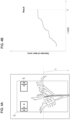
- the analysis using the image analysis program outputs a graph with a value L on the horizontal axis and the value of the stem diameter on the vertical axis, as shown in FIG. 4B .
- the plant stem typically tends to be thicker downward.
- the value of the stem diameter is greater as the value L is greater.
- the width of the stem is calculated at each point in the traced trajectory in accordance with the value of L. The width of the stem at each point is determined based on the distance between the markers 5 on the background plate 3, and the value of the determined width is the diameter of the stem at each point.
- the plant stem 2 may be covered by branches or leaves of the plant. With the covered portion of the plant stem 2 not identified in the analysis, the plant stem 2 may be determined as being discontinuous. Any such discontinuous portion of the curve of the stem edge obtained by the captured image may be complemented using an additional straight line or an additional spline curve with the image analysis program in the present embodiment. The image analysis thus identifies the plant stem 2 as being continuous.
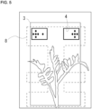
- FIG. 5 is a schematic diagram of an imaging mask 8 on an imaging screen viewed by the measurer when an image of the plant stem 2 and the background plate 3 is captured with the imager 1.
- the background plate 3 is simplified in the figure.
- the imaging mask 8 In capturing an image of the plant stem 2, the plant stem 2 is to be within the measurement area 7 on the background plate 3 shown in FIG. 2 .
- the imaging mask 8 In facilitate positioning of the plant stem 2 on the imaging screen, the imaging mask 8 in the shape of a Chinese character indicated with dotted lines is displayed.
- the imaging mask 8 is bright inside the shape of the Chinese character indicated with the dotted lines, with the outside being shadowed and not clearly visible to a person who captures an image.
- the plant stem 2 and the marker areas 4 are to be within the area of the imaging mask 8 for an imaging operation.
- the imaging mask 8 is displayed on the imaging screen viewed by the measurer in an imaging operation with the imager 1, and the plant stem 2 and the marker areas 4 are located within the frame. This allows the positional relationship between the plant stem 2 and the background plate 3 to be easily determined, thus improving the measurement accuracy of the diameter of the plant stem 2.
- the imaging mask 8 is simply a tool to facilitate the positioning of the plant stem 2 and may be optional on the imaging screen.
- the imaging mask 8 may not be in the shape of a Chinese character indicated with the dotted lines, and may be, for example, T-shaped, when the plant stem 2 and the marker areas 4 are within the frame.
- the imaging mask 8 may not have the shape of a character, and may have, for example, the shape of a plus sign.
- the method for measuring a dimension allows highly accurate measurement of the diameter of the plant stem 2 with little contact with the plant stem 2 except its contact for fixing the plant stem 2.
- the measurement error deviated from the true value can be specifically within the absolute value of 1 mm.
- plants are to achieve an optimal growth balance in each stage of growth. Measuring the diameter of the plant stem 2 provides an indicator to manage the vegetative growth for the growth balance.
- a method for measuring a dimension of a plant with an image of the plant captured with an imager (1) comprising:
Landscapes
- Physics & Mathematics (AREA)
- Engineering & Computer Science (AREA)
- General Physics & Mathematics (AREA)
- Theoretical Computer Science (AREA)
- Multimedia (AREA)
- Geometry (AREA)
- Computer Vision & Pattern Recognition (AREA)
- Life Sciences & Earth Sciences (AREA)
- Botany (AREA)
- Length Measuring Devices By Optical Means (AREA)
Abstract
Description
- The present invention relates to a method for measuring a dimension of a plant.
- An example known method for measuring a dimension of a plant uses a measurement tool such as a tape measure or a caliper placed in contact with a plant stem to measure the diameter of the plant stem. However, such contact with the plant during measurement may negatively affect the vegetative growth of the plant. Further, to measure the diameter of the plant stem at a branching portion of the plant, the branching portion can obstruct placement of the measurement tool into contact with the plant.
- Another example measurement method for plants may be a system that captures an image of a target plant from above with an imager and measures the characteristics of the plant stem through image analysis (refer to, for example, Patent Literature 1). Such image analysis allows simple and highly accurate measurement of a plant with little contact with the plant.
- A method for measuring a dimension of a plant using image analysis may use a white background plate including black markers placed behind the plant when an image of the plant is captured. However, placing the plant stem in close contact with the white background plate is actually difficult when the plant is three-dimensional and has branches and leaves, thus causing a measurement error resulting from the distance between the plant stem and the white background plate.
- Patent Literature 1:
Japanese Unexamined Patent Application Publication No. 2017-104037 - With the measurement method described above, the white background plate may be placed behind the plant to evaluate the degree of vegetative growth of the plant, and a digital camera or another imager may be used to capture an image of the plant stem. The diameter of the plant stem may then be measured using a predetermined image analysis program. Although the plant stem and the background plate are actually at a distance from each other, this method yields a value for the plant stem that is hypothetically in close contact with the white background plate. The measurement value of the plant stem diameter using the image analysis program can thus often exceed the true value. Further, measuring the distance between the plant stem and the white background plate using the image analysis program is difficult.
- In response to a measurement error described above, one or more aspects of the present invention are directed to an improved method for capturing an image of a plant stem and measuring a dimension of the plant to reduce an error in the measurement value of the diameter of the plant stem. The vegetative growth of the plant is to be managed based on the measurement value of the diameter of the plant stem measured with high reliability.
- The method for measuring a dimension of a plant according to the above aspects of the present invention may use a parameter to be measured other than the diameter of the plant stem.
- A method according to an aspect of the present invention is a method for measuring a dimension of a plant with an image of the plant captured with an imager. The method includes placing, behind the plant, a background plate including a dimensional reference in capturing the image of the plant with the imager, capturing an image of a dimensional measurement point of the plant a plurality of times with a distance between the dimensional measurement point and the background plate being unchanged and with an imaging distance being changed by moving the imager, and measuring the dimension of the plant based on a dimension at the dimensional measurement point in a plurality of images resulting from capturing the image the plurality of times using the dimensional reference included in the background plate and on a range of imaging with the imager in each of the plurality of images.
- In the above aspect to the present invention, an actual dimension of a target plant can be geometrically calculated using each parameter obtained in a plurality of imaging operations. In addition, when an image of the dimensional measurement point of the plant is captured, the distance between the dimensional measurement point and the background plate is not changed, and the imaging distance is changed simply by moving the imager. This allows highly accurate measurement of the dimension of the plant by calculation, independently of the distance between the dimensional measurement point and the background plate.
- In the above aspect of the present invention, the dimensional measurement point of the plant may include a diameter of a stem of the plant at a predetermined length below a growth point of the plant. The measurement point can be set in an optimal portion as an indicator to determine whether the level of the vegetative growth is appropriate for the plant. This allows the state of the vegetative growth of the plant to be obtained more accurately. In the above aspect of the present invention, the predetermined length may be, for example, 20 cm.
- In the above aspect of the present invention, the dimensional reference may include a plurality of markers located on the background plate being white. The plurality of markers may be at a predetermined distance from one another. This allows the dimensional measurement point and parameters of the imaging range with the imager to be calculated based on the distance between the plurality of markers in analysis using an image analysis program. In the above aspect of the present invention, the distance between the plurality of markers may be, for example, 30 cm.
- In the above aspect of the present invention, the capturing the image of the dimensional measurement point may include displaying an imaging mask being a frame on an imaging screen of the imager, and placing the dimensional measurement point and the dimensional reference inside the frame in the imaging mask. The frame may be brighter inside than outside the frame during capturing of the image. This facilitates positioning of the dimensional measurement point in capturing an image of the dimensional measurement point and prevents a measurement error due to use of a point being too close to an edge.
- In the above aspects of the present invention, the dimension of the plant can be efficiently measured with high accuracy to more efficiently manage plant cultivation based on the obtained dimensional value. For measuring the diameter of the plant stem, for example, the obtained value can be used to more accurately determine whether the plant has an appropriate level of the vegetative growth for more accurate adjustment of the amounts of water and fertilizer.
-
-
FIG. 1 is a schematic diagram of an imaging operation of a plant stem with an imager. -
FIG. 2 is a schematic diagram of a background plate showing its surface features in an embodiment of the present invention. -
FIG. 3A and FIG 3B are schematic diagrams of an imaging operation of a plant stem performed twice with a distance between the plant stem and the background plate being unchanged and with an imaging distance being changed simply by moving the imager in the embodiment of the present invention. -
FIG. 4A and FIG 4B are schematic diagrams of measurement of the diameter of a plant stem using an image analysis program after an imaging operation in the embodiment of the present invention. -
FIG. 5 is a schematic diagram of an imaging mask on an imaging screen viewed by a measurer when an image of a plant stem and the background plate is captured with the imager in the embodiment of the present invention. - [Example Use] In an example use, a method for measuring the diameter of a plant stem will be described as an example of a method for measuring a dimension of a plant. The method for measuring the diameter of a plant stem includes placing, behind the plant stem, a white background plate including markers located at a predetermined distance from one another to provide more accurate information on the position coordinates of a measurement point as a target. With the background plate placed behind the plant stem as the measurement target, an image of the plant stem and the background plate is captured, and the diameter of the plant stem in the image can be calculated based on the distance between the markers on the white background plate in analyzing the captured image.
- Placing the plant stem for which an image is captured with the imager in close contact with the white background plate is actually difficult when the plant growth point is three-dimensional and has branches and leaves. However, the plant stem in the captured image is hypothetically in close contact with the white background plate. Thus, measuring the diameter of the plant stem can involve a measurement error resulting from the distance between the plant stem and the white background plate, causing the measurement value of the diameter of the plant stem to be greater than the true value.
- To eliminate the measurement error resulting from the distance between the plant stem and the white background plate, an image of the plant stem is captured twice with the distance between the plant stem and the white background plate being unchanged and with the imaging distance being changed simply by moving the imager.
- In analyzing the captured image, an upper end of the stem of the captured plant is used as a growth point of the target plant, and the stem diameter is measured at, for example, 20 cm below the growth point. The stem diameter is calculated by geometry-based calculation using the stem diameter obtained in each of the two imaging operations as a parameter. The above parameters are all obtained based on the markers on the background plate.
- [Embodiment] The method for measuring a dimension of a plant according to the embodiment of the present invention will be described in detail with reference to the drawings. The measurement of the plant stem diameter will be described as the measurement of the dimension of the plant in the embodiment of the present invention. The method described below is a mere example of the method for measuring a dimension of a plant according to an embodiment of the present invention, and is not limited to the dimensional measurement target or the dimensional measurement procedure described below.
- <Dimensional Measurement Method>
FIG. 1 is a schematic diagram of an imaging operation of aplant stem 2 with animager 1. For example, theimager 1 may typically be a digital camera.FIG. 2 is a schematic diagram of abackground plate 3 inFIG. 1 showing its surface features. Thebackground plate 3 is typically white. An image of theplant stem 2 is captured with theimager 1 with thebackground plate 3 placed behind theplant stem 2. A measurement point is identified in image analysis, for which the diameter is then measured. In capturing an image of theplant stem 2, theplant stem 2 may be ideally in close contact with thebackground plate 3 behind theplant stem 2. However, theplant stem 2 and thebackground plate 3 are at a distance H2 between them when the plant growth point is three-dimensional and has branches and leaves. The growth point of the plant herein refers to an actively dividing cellular portion at the tip of the plant stem. - As shown in
FIG. 1 , although the true value of the diameter of theplant stem 2 is D1, the diameter is measured as D2 for theplant stem 2 that is hypothetically in close contact with thebackground plate 3. With the value D2 greater than the value D1, the measurement value of the diameter of theplant stem 2 exceeds the true value. In an imaging operation, the diameter D1 can be calculated when the distance H1 between theimager 1 and theplant stem 2 is known, but the distances H2 and H3 between theimager 1 and thebackground plate 3 are difficult to measure. Determining the distance H1, or the difference between H3 and H2, is thus difficult. For measuring the diameter of theplant stem 2, a method for eliminating such a measurement error is awaited. - The dimensional measurement of, for example, the diameter of the
plant stem 2 is performed using thebackground plate 3 shown inFIG. 2 and the captured image. Thebackground plate 3 includes twomarker areas 4 in the upper right and upper left in the direction shown inFIG. 2 , andmultiple markers 5 in each of themarker areas 4. The vertical direction of thebackground plate 3 in an imaging operation may be reversed upside down. Themarkers 5 herein each correspond to a dimensional reference in an aspect of the present invention. - The captured image of the
plant stem 2 with thebackground plate 3 placed behind theplant stem 2 includes themultiple markers 5 with predetermined reference position coordinates. The diameter of theplant stem 2 can be measured based on the number of pixels between themultiple markers 5 on the image and the number of pixels in the width of thetarget plant stem 2. Eachmarker 5 is typically a solid circle. At least onemarker 5 may be included in each of the twomarker areas 4. In an imaging operation with theimager 1, themarker areas 4 are defined to be fully within the imaging range. In an imaging operation, themarker areas 4 are to avoid being shadowed. - The
background plate 3 also includesmeasurement lines 6 that can be used to measure, for example, the width of plant leaves. The solid lines that intersect vertically and horizontally on thebackground plate 3 shown inFIG. 2 are all the measurement lines. Although the solid lines actually include scales to assist the dimensional measurement, the scales are not shown inFIG. 2 . In an imaging operation, theplant stem 2 is positioned to enter ameasurement area 7 indicated by the dotted lines. An approximate distance from the upper end of the plant to a portion for which the plant diameter is to be measured can be determined from themeasurement lines 6 and theplant stem 2 that are substantially parallel to each other in the imaging operation. - When an image of the
plant stem 2 is captured with theimager 1, thebackground plate 3 shown inFIG. 2 is placed behind theplant stem 2, and the imaging operation is performed twice with the distance between theplant stem 2 and thebackground plate 3 being unchanged and with the imaging distance being changed simply by moving theimager 1. The method for measuring the diameter of theplant stem 2 will be described below using the image obtained in this manner. -
FIG. 3A and FIG.3B are schematic diagrams of the imaging operation of theplant stem 2 performed twice with the distance between theplant stem 2 and thebackground plate 3 being unchanged and with the imaging distance being changed simply by moving theimager 1.FIG. 3A is a schematic diagram of the positional relationship between theimager 1, theplant stem 2, and thebackground plate 3 in the two imaging operations, viewed from above. Of the two imaging operations,position 1 is the position of theimager 1 capturing an image farther from theplant stem 2, andposition 2 is the position of theimager 1 capturing an image closer to theplant stem 2. The imaging range obtained based on the distance between themarkers 5 atposition 1 is x1, and the diameter of theplant stem 2 obtained in the same manner is d1. The imaging range obtained based on the distance between themarkers 5 atposition 2 is x2, and the diameter of theplant stem 2 obtained in the same manner is d2. The imaging range herein refers to the width of the image in the analysis using an image analysis program. - The true value d0 of the diameter of the
plant stem 2 can be calculated by geometry-based calculation using x1, x2, d1, and d2. The true value d0 can be written asFormula 1 below.
[Formula 1]
Formula 1 with the true values of two plants (a plant A and a plant B) having different stem diameters.[Table 1] Plant A Plant B d1 15.04 mm 5.20 mm x1 489.60 mm 546.46 mm d2 13.32 mm 5.00 mm x2 829.04 mm 909.12 mm d0 11.43394 mm 4.72610 mm True value 11.77 mm 4.90 mm Measurement error -0.33606 mm -0.17390 mm Formula 1 and each of the true values converges within the target range of the absolute value of 1 mm. -
FIG. 3B is a simplified view of images of the plant and thebackground plate 3 captured with theimager 1 atposition 1 andposition 2. The diameter of theplant stem 2 in each image is measured using the distance between themarkers 5 on thebackground plate 3 and the width of the target plant stem 2 in the captured image at each position. The distance between themarkers 5 on thebackground plate 3 in the image captured with theimager 1 may be actually obtained as the number of pixels included between the pixels corresponding to the centers of themarkers 5 in the image. The width of theplant stem 2 may be obtained as the number of pixels included between the pixels corresponding to the two horizontal edges of theplant stem 2. A distance W between themarkers 5 inFIG. 3B is, for example, 30 cm. In an imaging operation, the plant may not be located in the middle, or an image of the plant may be captured at an angle when thebackground plate 3 is within the imaging range. -
FIG. 4A and FIG.4B are schematic diagrams of measurement of the diameter of theplant stem 2 using a predetermined image analysis program after the imaging operation. Thebackground plate 3 is simplified in the figure. The image analysis program is prepared to calculate the diameter of theplant stem 2 at the dimensional measurement point using the image including theplant stem 2 and thebackground plate 3 captured with theimager 1. The image analysis program may be loaded into a common personal computer (PC) (not shown), be stored into a memory such as a read-only memory (ROM) included in the PC, and be executed by a central processing unit (CPU) included in the PC. For theimager 1 being a common digital camera, an image captured with theimager 1 is imported into the PC before being loaded and analyzed by the image analysis program. For theimager 1 being a smartphone or a tablet PC, for example, an image analysis program can also be loaded into the smartphone or the tablet PC for analyzing the image directly after the imaging operation. In the image analysis program, tracing from the upper end of the plant for which the image is captured downward in the direction of theplant stem 2 allows display of the traced trajectory on the image. The traced trajectory is indicated by a bold line inFIG. 4A . The starting point of the traced trajectory is the plant growth point. The measurement point for the diameter of theplant stem 2 is at 20 cm below the growth point. L represents the length downward from the growth point in the direction of theplant stem 2, and does not represent the vertical distance downward from the growth point. - The analysis using the image analysis program outputs a graph with a value L on the horizontal axis and the value of the stem diameter on the vertical axis, as shown in
FIG. 4B . The plant stem typically tends to be thicker downward. As shown inFIG. 4B , the value of the stem diameter is greater as the value L is greater. When the plant stem on the image is traced as shown inFIG. 4A in measuring the stem diameter, the width of the stem is calculated at each point in the traced trajectory in accordance with the value of L. The width of the stem at each point is determined based on the distance between themarkers 5 on thebackground plate 3, and the value of the determined width is the diameter of the stem at each point. - In an imaging operation, the
plant stem 2 may be covered by branches or leaves of the plant. With the covered portion of theplant stem 2 not identified in the analysis, theplant stem 2 may be determined as being discontinuous. Any such discontinuous portion of the curve of the stem edge obtained by the captured image may be complemented using an additional straight line or an additional spline curve with the image analysis program in the present embodiment. The image analysis thus identifies theplant stem 2 as being continuous. InFIG. 4B , the diameter of theplant stem 2 at L = 20 is the measurement value of the diameter of theplant stem 2. -
FIG. 5 is a schematic diagram of animaging mask 8 on an imaging screen viewed by the measurer when an image of theplant stem 2 and thebackground plate 3 is captured with theimager 1. Thebackground plate 3 is simplified in the figure. In capturing an image of theplant stem 2, theplant stem 2 is to be within themeasurement area 7 on thebackground plate 3 shown inFIG. 2 . To facilitate positioning of theplant stem 2 on the imaging screen, theimaging mask 8 in the shape of a Chinese character indicated with dotted lines is displayed. Although simplified inFIG. 5 , theimaging mask 8 is bright inside the shape of the Chinese character indicated with the dotted lines, with the outside being shadowed and not clearly visible to a person who captures an image. Theplant stem 2 and themarker areas 4 are to be within the area of theimaging mask 8 for an imaging operation. In the present embodiment, theimaging mask 8 is displayed on the imaging screen viewed by the measurer in an imaging operation with theimager 1, and theplant stem 2 and themarker areas 4 are located within the frame. This allows the positional relationship between theplant stem 2 and thebackground plate 3 to be easily determined, thus improving the measurement accuracy of the diameter of theplant stem 2. Theimaging mask 8 is simply a tool to facilitate the positioning of theplant stem 2 and may be optional on the imaging screen. Theimaging mask 8 may not be in the shape of a Chinese character indicated with the dotted lines, and may be, for example, T-shaped, when theplant stem 2 and themarker areas 4 are within the frame. Theimaging mask 8 may not have the shape of a character, and may have, for example, the shape of a plus sign. - The method for measuring a dimension according to the present embodiment allows highly accurate measurement of the diameter of the
plant stem 2 with little contact with theplant stem 2 except its contact for fixing theplant stem 2. For the measurement accuracy, the measurement error deviated from the true value can be specifically within the absolute value of 1 mm. In general, plants are to achieve an optimal growth balance in each stage of growth. Measuring the diameter of theplant stem 2 provides an indicator to manage the vegetative growth for the growth balance. - The elements in the aspects of the present invention below are identified with reference numerals used in the drawings to show the correspondence between these elements and the components in the embodiments.
- A method for measuring a dimension of a plant with an image of the plant captured with an imager (1), the method comprising:
- placing, behind the plant, a background plate (3) including a dimensional reference (5) in capturing the image of the plant with the imager;
- capturing an image of a dimensional measurement point of the plant a plurality of times with a distance between the dimensional measurement point and the background plate being unchanged and with an imaging distance being changed by moving the imager; and
- measuring the dimension of the plant based on a dimension at the dimensional measurement point in a plurality of images resulting from capturing the image the plurality of times using the dimensional reference included in the background plate and on a range of imaging with the imager in each of the plurality of images.
-
- 1
- imager
- 2
- plant stem
- 3
- background plate
- 4
- marker area
- 5
- marker
- 6
- measurement line
- 7
- measurement area
- 8
- imaging mask
Claims (4)
- A method for measuring a dimension of a plant with an image of the plant captured with an imager, the method comprising:placing, behind the plant, a background plate including a dimensional reference in capturing the image of the plant with the imager;capturing an image of a dimensional measurement point of the plant a plurality of times with a distance between the dimensional measurement point and the background plate being unchanged and with an imaging distance being changed by moving the imager; andmeasuring the dimension of the plant based on a value of a dimension at the dimensional measurement point in a plurality of images resulting from capturing the image the plurality of times using the dimensional reference included in the background plate and on a range of imaging with the imager in each of the plurality of images.
- The method according to claim 1, wherein
the dimensional measurement point of the plant includes a diameter of a stem of the plant at a predetermined length below a growth point of the plant. - The method according to claim 1 or claim 2, wherein
the dimensional reference includes a plurality of markers located on the background plate being white, and the plurality of markers are at a predetermined distance from one another. - The method according to any one of claims 1 to 3, wherein
the capturing the image of the dimensional measurement point includesdisplaying an imaging mask being a frame on an imaging screen of the imager, andplacing the dimensional measurement point and the dimensional reference at a predetermined position inside the imaging mask on the imaging screen of the imager to determine a positional relationship between the dimensional measurement point and the dimensional reference.
Applications Claiming Priority (2)
| Application Number | Priority Date | Filing Date | Title |
|---|---|---|---|
| JP2020143602A JP7639281B2 (en) | 2020-08-27 | 2020-08-27 | How to measure plant dimensions |
| PCT/JP2021/028073 WO2022044682A1 (en) | 2020-08-27 | 2021-07-29 | Method for measuring dimensions of plant |
Publications (3)
| Publication Number | Publication Date |
|---|---|
| EP4205536A1 true EP4205536A1 (en) | 2023-07-05 |
| EP4205536A4 EP4205536A4 (en) | 2024-01-24 |
| EP4205536B1 EP4205536B1 (en) | 2025-03-12 |
Family
ID=80352364
Family Applications (1)
| Application Number | Title | Priority Date | Filing Date |
|---|---|---|---|
| EP21861110.1A Active EP4205536B1 (en) | 2020-08-27 | 2021-07-29 | Method for measuring dimensions of a plant |
Country Status (5)
| Country | Link |
|---|---|
| US (1) | US12175693B2 (en) |
| EP (1) | EP4205536B1 (en) |
| JP (1) | JP7639281B2 (en) |
| CN (1) | CN116133517A (en) |
| WO (1) | WO2022044682A1 (en) |
Families Citing this family (1)
| Publication number | Priority date | Publication date | Assignee | Title |
|---|---|---|---|---|
| JP2022038669A (en) * | 2020-08-27 | 2022-03-10 | オムロン株式会社 | Tool for measuring plant dimensions and method for measuring plant dimensions |
Family Cites Families (15)
| Publication number | Priority date | Publication date | Assignee | Title |
|---|---|---|---|---|
| TWI401412B (en) * | 2009-11-13 | 2013-07-11 | Inst Information Industry | Automatic measurement system, method and recording medium for plant characteristics |
| JP5810494B2 (en) | 2010-09-07 | 2015-11-11 | 株式会社ニコン | Plant cultivation system, plant cultivation plant, harvesting device, and plant cultivation method |
| KR101748180B1 (en) | 2010-12-31 | 2017-06-16 | 주식회사 케이티 | Method and apparatus of measuring size of object in image |
| CN102967264B (en) * | 2012-12-07 | 2015-11-11 | 中国科学院新疆生态与地理研究所 | A kind of method based on digital image technical limit spacing shrub branch length |
| CN103162635A (en) | 2013-02-21 | 2013-06-19 | 北京林业大学 | Method for measuring diameter at breast height and tree height with camera |
| JP6303528B2 (en) * | 2014-01-22 | 2018-04-04 | 大日本印刷株式会社 | Dimension measuring apparatus, dimension measuring method, and program |
| JP2017042133A (en) | 2015-08-28 | 2017-03-02 | 株式会社日立製作所 | Plant growth rate calculation system and plant growth rate calculation method |
| JP6499570B2 (en) | 2015-12-08 | 2019-04-10 | ヤンマー株式会社 | Stem number measuring system and farming management system using it |
| CN106323182A (en) * | 2016-08-08 | 2017-01-11 | 北京农业信息技术研究中心 | Plant stalk diameter measuring method and device |
| CN207095515U (en) * | 2017-08-09 | 2018-03-13 | 南京林业大学 | A kind of phytomorph three-dimensional image acquisition apparatus |
| US10687476B2 (en) | 2017-09-11 | 2020-06-23 | Bloom Automation, Inc. | Automated plant trimmer |
| JP2020099215A (en) | 2018-12-20 | 2020-07-02 | 三菱重工機械システム株式会社 | Plant management system |
| KR102139459B1 (en) * | 2019-03-19 | 2020-07-30 | 주식회사 쉘파스페이스 | Method, Apparatus and System for monitoring and growing of plant |
| CN209802305U (en) | 2019-06-19 | 2019-12-17 | 中国农业科学院农业环境与可持续发展研究所 | system for be used for crops output aassessment |
| CN210491057U (en) | 2019-09-17 | 2020-05-08 | 陈�峰 | Crop plant height measuring equipment based on Internet of things |
-
2020
- 2020-08-27 JP JP2020143602A patent/JP7639281B2/en active Active
-
2021
- 2021-07-29 US US18/007,304 patent/US12175693B2/en active Active
- 2021-07-29 WO PCT/JP2021/028073 patent/WO2022044682A1/en not_active Ceased
- 2021-07-29 CN CN202180059751.9A patent/CN116133517A/en active Pending
- 2021-07-29 EP EP21861110.1A patent/EP4205536B1/en active Active
Also Published As
| Publication number | Publication date |
|---|---|
| EP4205536A4 (en) | 2024-01-24 |
| US20230289990A1 (en) | 2023-09-14 |
| US12175693B2 (en) | 2024-12-24 |
| EP4205536B1 (en) | 2025-03-12 |
| JP2022038893A (en) | 2022-03-10 |
| WO2022044682A1 (en) | 2022-03-03 |
| JP7639281B2 (en) | 2025-03-05 |
| CN116133517A (en) | 2023-05-16 |
Similar Documents
| Publication | Publication Date | Title |
|---|---|---|
| US11913771B2 (en) | Information processing device, object measuring system, object measuring method, and program storing medium | |
| CN114220757B (en) | Wafer detection alignment method, device and system and computer medium | |
| KR101974638B1 (en) | Apparatus for processing plant images and method thereof | |
| US11562478B2 (en) | Method and system for testing field of view | |
| CN108833912A (en) | A kind of measurement method and system of video camera machine core optical axis center and field angle | |
| CN111105466A (en) | Calibration method of camera in CT system | |
| CN107345789A (en) | A kind of pcb board hole location detecting device and method | |
| CN112902869B (en) | Laser plane adjustment method and device for orbital profile measurement system | |
| CN113299213A (en) | Crease detection method and device | |
| CN104019772A (en) | Bridge structure concrete surface voids and pits area tester and detection method | |
| CN101776437B (en) | Calibration technology for vision sub-pixel of embedded type machine with optical path adjustment | |
| EP4205536B1 (en) | Method for measuring dimensions of a plant | |
| US20230349687A1 (en) | Plant dimension measuring method | |
| CN119509463A (en) | A monocular vision tower span measurement method based on RTK correction | |
| CN107883825A (en) | A kind of intelligent visual detection method for the slide measure zero graduation line that aligns | |
| CN120070316B (en) | Automatic detection method for quality of concealed engineering steel bar based on computer vision technology | |
| CN112902878B (en) | Laser plane adjustment method and device for track geometry detection system | |
| CN109003302A (en) | A method of Human Height is calculated to the identification of face by camera | |
| CN117152361B (en) | Remote sensing image visibility estimation method based on attention mechanism | |
| CN114359652B (en) | A positioning detection method based on deep learning and monocular large field of view plane measurement | |
| CN106969707B (en) | A detection device and its control method | |
| CN116634134A (en) | Method, device, storage medium and electronic equipment for imaging system calibration | |
| US20230289992A1 (en) | Plant dimension measuring tool and plant dimension measuring method | |
| CN114693637A (en) | Quantitative detection method for image sawtooth distortion of scanning thermal imager | |
| CN112747687B (en) | Line structure light vision measurement calibration method and system |
Legal Events
| Date | Code | Title | Description |
|---|---|---|---|
| STAA | Information on the status of an ep patent application or granted ep patent |
Free format text: STATUS: THE INTERNATIONAL PUBLICATION HAS BEEN MADE |
|
| PUAI | Public reference made under article 153(3) epc to a published international application that has entered the european phase |
Free format text: ORIGINAL CODE: 0009012 |
|
| STAA | Information on the status of an ep patent application or granted ep patent |
Free format text: STATUS: REQUEST FOR EXAMINATION WAS MADE |
|
| 17P | Request for examination filed |
Effective date: 20230127 |
|
| AK | Designated contracting states |
Kind code of ref document: A1 Designated state(s): AL AT BE BG CH CY CZ DE DK EE ES FI FR GB GR HR HU IE IS IT LI LT LU LV MC MK MT NL NO PL PT RO RS SE SI SK SM TR |
|
| DAV | Request for validation of the european patent (deleted) | ||
| DAX | Request for extension of the european patent (deleted) | ||
| REG | Reference to a national code |
Ref country code: DE Ref legal event code: R079 Ipc: G01B0011020000 Ref country code: DE Ref legal event code: R079 Ref document number: 602021027636 Country of ref document: DE Free format text: PREVIOUS MAIN CLASS: A01G0007000000 Ipc: G01B0011020000 |
|
| A4 | Supplementary search report drawn up and despatched |
Effective date: 20240103 |
|
| RIC1 | Information provided on ipc code assigned before grant |
Ipc: A01G 7/00 20060101ALI20231220BHEP Ipc: G06T 7/62 20170101ALI20231220BHEP Ipc: G01B 11/08 20060101ALI20231220BHEP Ipc: G01B 11/02 20060101AFI20231220BHEP |
|
| GRAP | Despatch of communication of intention to grant a patent |
Free format text: ORIGINAL CODE: EPIDOSNIGR1 |
|
| STAA | Information on the status of an ep patent application or granted ep patent |
Free format text: STATUS: GRANT OF PATENT IS INTENDED |
|
| RIC1 | Information provided on ipc code assigned before grant |
Ipc: G06V 20/60 20220101ALI20241017BHEP Ipc: G06V 10/10 20220101ALI20241017BHEP Ipc: G06V 10/12 20220101ALI20241017BHEP Ipc: G06T 7/62 20170101ALI20241017BHEP Ipc: G01B 11/08 20060101ALI20241017BHEP Ipc: G01B 11/02 20060101AFI20241017BHEP |
|
| INTG | Intention to grant announced |
Effective date: 20241031 |
|
| GRAS | Grant fee paid |
Free format text: ORIGINAL CODE: EPIDOSNIGR3 |
|
| GRAA | (expected) grant |
Free format text: ORIGINAL CODE: 0009210 |
|
| STAA | Information on the status of an ep patent application or granted ep patent |
Free format text: STATUS: THE PATENT HAS BEEN GRANTED |
|
| AK | Designated contracting states |
Kind code of ref document: B1 Designated state(s): AL AT BE BG CH CY CZ DE DK EE ES FI FR GB GR HR HU IE IS IT LI LT LU LV MC MK MT NL NO PL PT RO RS SE SI SK SM TR |
|
| REG | Reference to a national code |
Ref country code: GB Ref legal event code: FG4D |
|
| REG | Reference to a national code |
Ref country code: CH Ref legal event code: EP |
|
| REG | Reference to a national code |
Ref country code: DE Ref legal event code: R096 Ref document number: 602021027636 Country of ref document: DE |
|
| REG | Reference to a national code |
Ref country code: IE Ref legal event code: FG4D |
|
| REG | Reference to a national code |
Ref country code: NL Ref legal event code: FP |
|
| PG25 | Lapsed in a contracting state [announced via postgrant information from national office to epo] |
Ref country code: RS Free format text: LAPSE BECAUSE OF FAILURE TO SUBMIT A TRANSLATION OF THE DESCRIPTION OR TO PAY THE FEE WITHIN THE PRESCRIBED TIME-LIMIT Effective date: 20250612 |
|
| PG25 | Lapsed in a contracting state [announced via postgrant information from national office to epo] |
Ref country code: FI Free format text: LAPSE BECAUSE OF FAILURE TO SUBMIT A TRANSLATION OF THE DESCRIPTION OR TO PAY THE FEE WITHIN THE PRESCRIBED TIME-LIMIT Effective date: 20250312 |
|
| PG25 | Lapsed in a contracting state [announced via postgrant information from national office to epo] |
Ref country code: ES Free format text: LAPSE BECAUSE OF FAILURE TO SUBMIT A TRANSLATION OF THE DESCRIPTION OR TO PAY THE FEE WITHIN THE PRESCRIBED TIME-LIMIT Effective date: 20250312 |
|
| REG | Reference to a national code |
Ref country code: LT Ref legal event code: MG9D |
|
| PG25 | Lapsed in a contracting state [announced via postgrant information from national office to epo] |
Ref country code: NO Free format text: LAPSE BECAUSE OF FAILURE TO SUBMIT A TRANSLATION OF THE DESCRIPTION OR TO PAY THE FEE WITHIN THE PRESCRIBED TIME-LIMIT Effective date: 20250612 |
|
| PG25 | Lapsed in a contracting state [announced via postgrant information from national office to epo] |
Ref country code: HR Free format text: LAPSE BECAUSE OF FAILURE TO SUBMIT A TRANSLATION OF THE DESCRIPTION OR TO PAY THE FEE WITHIN THE PRESCRIBED TIME-LIMIT Effective date: 20250312 |
|
| PG25 | Lapsed in a contracting state [announced via postgrant information from national office to epo] |
Ref country code: LV Free format text: LAPSE BECAUSE OF FAILURE TO SUBMIT A TRANSLATION OF THE DESCRIPTION OR TO PAY THE FEE WITHIN THE PRESCRIBED TIME-LIMIT Effective date: 20250312 |
|
| PG25 | Lapsed in a contracting state [announced via postgrant information from national office to epo] |
Ref country code: BG Free format text: LAPSE BECAUSE OF FAILURE TO SUBMIT A TRANSLATION OF THE DESCRIPTION OR TO PAY THE FEE WITHIN THE PRESCRIBED TIME-LIMIT Effective date: 20250312 Ref country code: GR Free format text: LAPSE BECAUSE OF FAILURE TO SUBMIT A TRANSLATION OF THE DESCRIPTION OR TO PAY THE FEE WITHIN THE PRESCRIBED TIME-LIMIT Effective date: 20250613 |
|
| REG | Reference to a national code |
Ref country code: AT Ref legal event code: MK05 Ref document number: 1775322 Country of ref document: AT Kind code of ref document: T Effective date: 20250312 |
|
| PG25 | Lapsed in a contracting state [announced via postgrant information from national office to epo] |
Ref country code: SE Free format text: LAPSE BECAUSE OF FAILURE TO SUBMIT A TRANSLATION OF THE DESCRIPTION OR TO PAY THE FEE WITHIN THE PRESCRIBED TIME-LIMIT Effective date: 20250312 |
|
| PG25 | Lapsed in a contracting state [announced via postgrant information from national office to epo] |
Ref country code: SM Free format text: LAPSE BECAUSE OF FAILURE TO SUBMIT A TRANSLATION OF THE DESCRIPTION OR TO PAY THE FEE WITHIN THE PRESCRIBED TIME-LIMIT Effective date: 20250312 |
|
| PG25 | Lapsed in a contracting state [announced via postgrant information from national office to epo] |
Ref country code: PT Free format text: LAPSE BECAUSE OF FAILURE TO SUBMIT A TRANSLATION OF THE DESCRIPTION OR TO PAY THE FEE WITHIN THE PRESCRIBED TIME-LIMIT Effective date: 20250714 |
|
| PG25 | Lapsed in a contracting state [announced via postgrant information from national office to epo] |
Ref country code: PL Free format text: LAPSE BECAUSE OF FAILURE TO SUBMIT A TRANSLATION OF THE DESCRIPTION OR TO PAY THE FEE WITHIN THE PRESCRIBED TIME-LIMIT Effective date: 20250312 Ref country code: IT Free format text: LAPSE BECAUSE OF FAILURE TO SUBMIT A TRANSLATION OF THE DESCRIPTION OR TO PAY THE FEE WITHIN THE PRESCRIBED TIME-LIMIT Effective date: 20250312 |
|
| PG25 | Lapsed in a contracting state [announced via postgrant information from national office to epo] |
Ref country code: AT Free format text: LAPSE BECAUSE OF FAILURE TO SUBMIT A TRANSLATION OF THE DESCRIPTION OR TO PAY THE FEE WITHIN THE PRESCRIBED TIME-LIMIT Effective date: 20250312 |
|
| PG25 | Lapsed in a contracting state [announced via postgrant information from national office to epo] |
Ref country code: CZ Free format text: LAPSE BECAUSE OF FAILURE TO SUBMIT A TRANSLATION OF THE DESCRIPTION OR TO PAY THE FEE WITHIN THE PRESCRIBED TIME-LIMIT Effective date: 20250312 Ref country code: EE Free format text: LAPSE BECAUSE OF FAILURE TO SUBMIT A TRANSLATION OF THE DESCRIPTION OR TO PAY THE FEE WITHIN THE PRESCRIBED TIME-LIMIT Effective date: 20250312 |
|
| PG25 | Lapsed in a contracting state [announced via postgrant information from national office to epo] |
Ref country code: RO Free format text: LAPSE BECAUSE OF FAILURE TO SUBMIT A TRANSLATION OF THE DESCRIPTION OR TO PAY THE FEE WITHIN THE PRESCRIBED TIME-LIMIT Effective date: 20250312 |
|
| PG25 | Lapsed in a contracting state [announced via postgrant information from national office to epo] |
Ref country code: SK Free format text: LAPSE BECAUSE OF FAILURE TO SUBMIT A TRANSLATION OF THE DESCRIPTION OR TO PAY THE FEE WITHIN THE PRESCRIBED TIME-LIMIT Effective date: 20250312 |
|
| PG25 | Lapsed in a contracting state [announced via postgrant information from national office to epo] |
Ref country code: IS Free format text: LAPSE BECAUSE OF FAILURE TO SUBMIT A TRANSLATION OF THE DESCRIPTION OR TO PAY THE FEE WITHIN THE PRESCRIBED TIME-LIMIT Effective date: 20250712 |
|
| REG | Reference to a national code |
Ref country code: DE Ref legal event code: R097 Ref document number: 602021027636 Country of ref document: DE |
|
| PG25 | Lapsed in a contracting state [announced via postgrant information from national office to epo] |
Ref country code: DK Free format text: LAPSE BECAUSE OF FAILURE TO SUBMIT A TRANSLATION OF THE DESCRIPTION OR TO PAY THE FEE WITHIN THE PRESCRIBED TIME-LIMIT Effective date: 20250312 |
|
| PLBE | No opposition filed within time limit |
Free format text: ORIGINAL CODE: 0009261 |
|
| STAA | Information on the status of an ep patent application or granted ep patent |
Free format text: STATUS: NO OPPOSITION FILED WITHIN TIME LIMIT |
|
| REG | Reference to a national code |
Ref country code: CH Ref legal event code: L10 Free format text: ST27 STATUS EVENT CODE: U-0-0-L10-L00 (AS PROVIDED BY THE NATIONAL OFFICE) Effective date: 20260121 |
|
| REG | Reference to a national code |
Ref country code: DE Ref legal event code: R119 Ref document number: 602021027636 Country of ref document: DE |
|
| 26N | No opposition filed |
Effective date: 20251215 |
|
| REG | Reference to a national code |
Ref country code: CH Ref legal event code: H13 Free format text: ST27 STATUS EVENT CODE: U-0-0-H10-H13 (AS PROVIDED BY THE NATIONAL OFFICE) Effective date: 20260224 |
|
| REG | Reference to a national code |
Ref country code: NL Ref legal event code: MM Effective date: 20250801 |
|
| PG25 | Lapsed in a contracting state [announced via postgrant information from national office to epo] |
Ref country code: LU Free format text: LAPSE BECAUSE OF NON-PAYMENT OF DUE FEES Effective date: 20250729 |
|
| GBPC | Gb: european patent ceased through non-payment of renewal fee |
Effective date: 20250729 |
|
| REG | Reference to a national code |
Ref country code: BE Ref legal event code: MM Effective date: 20250731 |
|
| PG25 | Lapsed in a contracting state [announced via postgrant information from national office to epo] |
Ref country code: GB Free format text: LAPSE BECAUSE OF NON-PAYMENT OF DUE FEES Effective date: 20250729 |
|
| PG25 | Lapsed in a contracting state [announced via postgrant information from national office to epo] |
Ref country code: DE Free format text: LAPSE BECAUSE OF NON-PAYMENT OF DUE FEES Effective date: 20260203 |
|
| PG25 | Lapsed in a contracting state [announced via postgrant information from national office to epo] |
Ref country code: BE Free format text: LAPSE BECAUSE OF NON-PAYMENT OF DUE FEES Effective date: 20250731 |
|
| PG25 | Lapsed in a contracting state [announced via postgrant information from national office to epo] |
Ref country code: NL Free format text: LAPSE BECAUSE OF NON-PAYMENT OF DUE FEES Effective date: 20250801 |
|
| PG25 | Lapsed in a contracting state [announced via postgrant information from national office to epo] |
Ref country code: FR Free format text: LAPSE BECAUSE OF NON-PAYMENT OF DUE FEES Effective date: 20250731 |
|
| PG25 | Lapsed in a contracting state [announced via postgrant information from national office to epo] |
Ref country code: CH Free format text: LAPSE BECAUSE OF NON-PAYMENT OF DUE FEES Effective date: 20250731 |
|
| PG25 | Lapsed in a contracting state [announced via postgrant information from national office to epo] |
Ref country code: LT Free format text: LAPSE BECAUSE OF FAILURE TO SUBMIT A TRANSLATION OF THE DESCRIPTION OR TO PAY THE FEE WITHIN THE PRESCRIBED TIME-LIMIT Effective date: 20250312 |
|
| PG25 | Lapsed in a contracting state [announced via postgrant information from national office to epo] |
Ref country code: IE Free format text: LAPSE BECAUSE OF NON-PAYMENT OF DUE FEES Effective date: 20250729 |
|
| PG25 | Lapsed in a contracting state [announced via postgrant information from national office to epo] |
Ref country code: MC Free format text: LAPSE BECAUSE OF FAILURE TO SUBMIT A TRANSLATION OF THE DESCRIPTION OR TO PAY THE FEE WITHIN THE PRESCRIBED TIME-LIMIT Effective date: 20250312 |
|
| PG25 | Lapsed in a contracting state [announced via postgrant information from national office to epo] |
Ref country code: CY Free format text: LAPSE BECAUSE OF FAILURE TO SUBMIT A TRANSLATION OF THE DESCRIPTION OR TO PAY THE FEE WITHIN THE PRESCRIBED TIME-LIMIT Effective date: 20250312 |