EP4205459B1 - Verfahren, vorrichtungen und system für direktzugriff bei steuerkanalwiederholung - Google Patents
Verfahren, vorrichtungen und system für direktzugriff bei steuerkanalwiederholung Download PDFInfo
- Publication number
- EP4205459B1 EP4205459B1 EP21790601.5A EP21790601A EP4205459B1 EP 4205459 B1 EP4205459 B1 EP 4205459B1 EP 21790601 A EP21790601 A EP 21790601A EP 4205459 B1 EP4205459 B1 EP 4205459B1
- Authority
- EP
- European Patent Office
- Prior art keywords
- coreset
- dci
- pdcch
- wireless device
- random
- Prior art date
- Legal status (The legal status is an assumption and is not a legal conclusion. Google has not performed a legal analysis and makes no representation as to the accuracy of the status listed.)
- Active
Links
Images


Classifications
-
- H—ELECTRICITY
- H04—ELECTRIC COMMUNICATION TECHNIQUE
- H04W—WIRELESS COMMUNICATION NETWORKS
- H04W52/00—Power management, e.g. Transmission Power Control [TPC] or power classes
- H04W52/04—Transmission power control [TPC]
- H04W52/38—TPC being performed in particular situations
- H04W52/50—TPC being performed in particular situations at the moment of starting communication in a multiple access environment
-
- H—ELECTRICITY
- H04—ELECTRIC COMMUNICATION TECHNIQUE
- H04W—WIRELESS COMMUNICATION NETWORKS
- H04W72/00—Local resource management
- H04W72/20—Control channels or signalling for resource management
- H04W72/23—Control channels or signalling for resource management in the downlink direction of a wireless link, i.e. towards a terminal
-
- H—ELECTRICITY
- H04—ELECTRIC COMMUNICATION TECHNIQUE
- H04L—TRANSMISSION OF DIGITAL INFORMATION, e.g. TELEGRAPHIC COMMUNICATION
- H04L5/00—Arrangements affording multiple use of the transmission path
- H04L5/003—Arrangements for allocating sub-channels of the transmission path
- H04L5/0053—Allocation of signalling, i.e. of overhead other than pilot signals
-
- H—ELECTRICITY
- H04—ELECTRIC COMMUNICATION TECHNIQUE
- H04W—WIRELESS COMMUNICATION NETWORKS
- H04W52/00—Power management, e.g. Transmission Power Control [TPC] or power classes
- H04W52/04—Transmission power control [TPC]
- H04W52/18—TPC being performed according to specific parameters
- H04W52/24—TPC being performed according to specific parameters using SIR [Signal to Interference Ratio] or other wireless path parameters
- H04W52/242—TPC being performed according to specific parameters using SIR [Signal to Interference Ratio] or other wireless path parameters taking into account path loss
-
- H—ELECTRICITY
- H04—ELECTRIC COMMUNICATION TECHNIQUE
- H04W—WIRELESS COMMUNICATION NETWORKS
- H04W74/00—Wireless channel access
- H04W74/08—Non-scheduled access, e.g. ALOHA
- H04W74/0833—Random access procedures, e.g. with 4-step access
-
- H—ELECTRICITY
- H04—ELECTRIC COMMUNICATION TECHNIQUE
- H04W—WIRELESS COMMUNICATION NETWORKS
- H04W74/00—Wireless channel access
- H04W74/08—Non-scheduled access, e.g. ALOHA
- H04W74/0833—Random access procedures, e.g. with 4-step access
- H04W74/0836—Random access procedures, e.g. with 4-step access with 2-step access
-
- H—ELECTRICITY
- H04—ELECTRIC COMMUNICATION TECHNIQUE
- H04W—WIRELESS COMMUNICATION NETWORKS
- H04W74/00—Wireless channel access
- H04W74/08—Non-scheduled access, e.g. ALOHA
- H04W74/0833—Random access procedures, e.g. with 4-step access
- H04W74/0838—Random access procedures, e.g. with 4-step access using contention-free random access [CFRA]
Definitions
- a base station included in the RAN 104 may include one or more sets of antennas for communicating with the wireless device 106 over the air interface.
- one or more of the base stations may include three sets of antennas to respectively control three cells (or sectors).
- the size of a cell may be determined by a range at which a receiver (e.g., a base station receiver) can successfully receive the transmissions from a transmitter (e.g., a wireless device transmitter) operating in the cell.
- the cells of the base stations may provide radio coverage to the wireless device 106 over a wide geographic area to support wireless device mobility.
- one or more of the base stations in the RAN 104 may be implemented as a sectored site with more or less than three sectors.
- One or more of the base stations in the RAN 104 may be implemented as an access point, as a baseband processing unit coupled to several remote radio heads (RRHs), and/or as a repeater or relay node used to extend the coverage area of a donor node.
- RRHs remote radio heads
- a baseband processing unit coupled to RRHs may be part of a centralized or cloud RAN architecture, where the baseband processing unit may be either centralized in a pool of baseband processing units or virtualized.
- the RAN 104 may be deployed as a homogenous network of macrocell base stations that have similar antenna patterns and similar high-level transmit powers.
- the RAN 104 may be deployed as a heterogeneous network.
- small cell base stations may be used to provide small coverage areas, for example, coverage areas that overlap with the comparatively larger coverage areas provided by macrocell base stations.
- the small coverage areas may be provided in areas with high data traffic (or so-called "hotspots") or in areas with weak macrocell coverage.
- Examples of small cell base stations include, in order of decreasing coverage area, microcell base stations, picocell base stations, and femtocell base stations or home base stations.
- 3GPP The Third-Generation Partnership Project (3GPP) was formed in 1998 to provide global standardization of specifications for mobile communication networks similar to the mobile communication network 100 in FIG. 1A .
- 3GPP has produced specifications for three generations of mobile networks: a third generation (3G) network known as Universal Mobile Telecommunications System (UMTS), a fourth generation (4G) network known as Long-Term Evolution (LTE), and a fifth generation (5G) network known as 5G System (5GS).
- UMTS Universal Mobile Telecommunications System
- 4G fourth generation
- LTE Long-Term Evolution
- 5G 5G System
- Embodiments of the present disclosure are described with reference to the RAN of a 3GPP 5G network, referred to as next-generation RAN (NG-RAN).
- NG-RAN next-generation RAN
- Embodiments may be applicable to RANs of other mobile communication networks, such as the RAN 104 in FIG.
- NG-RAN implements 5G radio access technology known as New Radio (NR) and may be provisioned to implement 4G radio access technology or other radio access technologies, including non-3GPP radio access technologies.
- NR New Radio
- FIG. 1B illustrates another example mobile communication network 150 in which embodiments of the present disclosure may be implemented.
- Mobile communication network 150 may be, for example, a PLMN run by a network operator.
- mobile communication network 150 includes a 5G core network (5G-CN) 152, an NG-RAN 154, and UEs 156A and 156B (collectively UEs 156). These components may be implemented and operate in the same or similar manner as corresponding components described with respect to FIG. 1A .
- 5G-CN 5G core network
- NG-RAN 154 a 5G core network
- UEs 156A and 156B collectively UEs 156
- the 5G-CN 152 provides the UEs 156 with an interface to one or more DNs, such as public DNs (e.g., the Internet), private DNs, and/or intra-operator DNs.
- the 5G-CN 152 may set up end-to-end connections between the UEs 156 and the one or more DNs, authenticate the UEs 156, and provide charging functionality.
- the basis of the 5G-CN 152 may be a service-based architecture. This means that the architecture of the nodes making up the 5G-CN 152 may be defined as network functions that offer services via interfaces to other network functions.
- the network functions of the 5G-CN 152 may be implemented in several ways, including as network elements on dedicated or shared hardware, as software instances running on dedicated or shared hardware, or as virtualized functions instantiated on a platform (e.g., a cloud-based platform).
- the 5G-CN 152 includes an Access and Mobility Management Function (AMF) 158A and a User Plane Function (UPF) 158B, which are shown as one component AMF/UPF 158 in FIG. 1B for ease of illustration.
- AMF Access and Mobility Management Function
- UPF User Plane Function
- the UPF 158B may serve as a gateway between the NG-RAN 154 and the one or more DNs.
- the UPF 158B may perform functions such as packet routing and forwarding, packet inspection and user plane policy rule enforcement, traffic usage reporting, uplink classification to support routing of traffic flows to the one or more DNs, quality of service (QoS) handling for the user plane (e.g., packet filtering, gating, uplink/downlink rate enforcement, and uplink traffic verification), downlink packet buffering, and downlink data notification triggering.
- QoS quality of service
- the UPF 158B may serve as an anchor point for intra-/inter-Radio Access Technology (RAT) mobility, an external protocol (or packet) data unit (PDU) session point of interconnect to the one or more DNs, and/or a branching point to support a multi-homed PDU session.
- the UEs 156 may be configured to receive services through a PDU session, which is a logical connection between a UE and a DN.
- the AMF 158A may perform functions such as Non-Access Stratum (NAS) signaling termination, NAS signaling security, Access Stratum (AS) security control, inter-CN node signaling for mobility between 3GPP access networks, idle mode UE reachability (e.g., control and execution of paging retransmission), registration area management, intra-system and inter-system mobility support, access authentication, access authorization including checking of roaming rights, mobility management control (subscription and policies), network slicing support, and/or session management function (SMF) selection.
- NAS may refer to the functionality operating between a CN and a UE
- AS may refer to the functionality operating between the UE and a RAN.
- the 5G-CN 152 may include one or more additional network functions that are not shown in FIG. 1B for the sake of clarity.
- the 5G-CN 152 may include one or more of a Session Management Function (SMF), an NR Repository Function (NRF), a Policy Control Function (PCF), a Network Exposure Function (NEF), a Unified Data Management (UDM), an Application Function (AF), and/or an Authentication Server Function (AUSF).
- SMF Session Management Function
- NRF NR Repository Function
- PCF Policy Control Function
- NEF Network Exposure Function
- UDM Unified Data Management
- AF Application Function
- AUSF Authentication Server Function
- the NG-RAN 154 may connect the 5G-CN 152 to the UEs 156 through radio communications over the air interface.
- the NG-RAN 154 may include one or more gNBs, illustrated as gNB 160A and gNB 160B (collectively gNBs 160) and/or one or more ng-eNBs, illustrated as ng-eNB 162A and ng-eNB 162B (collectively ng-eNBs 162).
- the gNBs 160 and ng-eNBs 162 may be more generically referred to as base stations.
- the gNBs 160 and ng-eNBs 162 may include one or more sets of antennas for communicating with the UEs 156 over an air interface.
- one or more of the gNBs 160 and/or one or more of the ng-eNBs 162 may include three sets of antennas to respectively control three cells (or sectors). Together, the cells of the gNBs 160 and the ng-eNBs 162 may provide radio coverage to the UEs 156 over a wide geographic area to support UE mobility.
- the gNBs 160 and/or the ng-eNBs 162 may be connected to the 5G-CN 152 by means of an NG interface and to other base stations by an Xn interface.
- the NG and Xn interfaces may be established using direct physical connections and/or indirect connections over an underlying transport network, such as an internet protocol (IP) transport network.
- IP internet protocol
- the gNBs 160 and/or the ng-eNBs 162 may be connected to the UEs 156 by means of a Uu interface.
- gNB 160A may be connected to the UE 156A by means of a Uu interface.
- the NG, Xn, and Uu interfaces are associated with a protocol stack.
- the protocol stacks associated with the interfaces may be used by the network elements in FIG. 1B to exchange data and signaling messages and may include two planes: a user plane and a control plane.
- the user plane may handle data of interest to a user.
- the control plane may handle signaling messages of interest to the network elements.
- the gNBs 160 and/or the ng-eNBs 162 may be connected to one or more AMF/UPF functions of the 5G-CN 152, such as the AMF/UPF 158, by means of one or more NG interfaces.
- the gNB 160A may be connected to the UPF 158B of the AMF/UPF 158 by means of an NG-User plane (NG-U) interface.
- the NG-U interface may provide delivery (e.g., non-guaranteed delivery) of user plane PDUs between the gNB 160A and the UPF 158B.
- the gNB 160A may be connected to the AMF 158A by means of an NG-Control plane (NG-C) interface.
- the NG-C interface may provide, for example, NG interface management, UE context management, UE mobility management, transport of NAS messages, paging, PDU session management, and configuration transfer and/or warning message transmission.
- the gNBs 160 may provide NR user plane and control plane protocol terminations towards the UEs 156 over the Uu interface.
- the gNB 160A may provide NR user plane and control plane protocol terminations toward the UE 156A over a Uu interface associated with a first protocol stack.
- the ng-eNBs 162 may provide Evolved UMTS Terrestrial Radio Access (E-UTRA) user plane and control plane protocol terminations towards the UEs 156 over a Uu interface, where E-UTRA refers to the 3GPP 4G radio-access technology.
- E-UTRA refers to the 3GPP 4G radio-access technology.
- the ng-eNB 162B may provide E-UTRA user plane and control plane protocol terminations towards the UE 156B over a Uu interface associated with a second protocol stack.
- the 5G-CN 152 was described as being configured to handle NR and 4G radio accesses. It will be appreciated by one of ordinary skill in the art that it may be possible for NR to connect to a 4G core network in a mode known as "non-standalone operation.” In non-standalone operation, a 4G core network is used to provide (or at least support) control-plane functionality (e.g., initial access, mobility, and paging). Although only one AMF/UPF 158 is shown in FIG. 1B , one gNB or ng-eNB may be connected to multiple AMF/UPF nodes to provide redundancy and/or to load share across the multiple AMF/UPF nodes.
- an interface (e.g., Uu, Xn, and NG interfaces) between the network elements in FIG. 1B may be associated with a protocol stack that the network elements use to exchange data and signaling messages.
- a protocol stack may include two planes: a user plane and a control plane. The user plane may handle data of interest to a user, and the control plane may handle signaling messages of interest to the network elements.
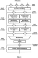
- FIG. 2A and FIG. 2B respectively illustrate examples of NR user plane and NR control plane protocol stacks for the Uu interface that lies between a UE 210 and a gNB 220.
- the protocol stacks illustrated in FIG. 2A and FIG. 2B may be the same or similar to those used for the Uu interface between, for example, the UE 156A and the gNB 160A shown in FIG. 1B .
- FIG. 2A illustrates a NR user plane protocol stack comprising five layers implemented in the UE 210 and the gNB 220.
- PHYs physical layers
- PHYs 211 and 221 may provide transport services to the higher layers of the protocol stack and may correspond to layer 1 of the Open Systems Interconnection (OSI) model.
- the next four protocols above PHYs 211 and 221 comprise media access control layers (MACs) 212 and 222, radio link control layers (RLCs) 213 and 223, packet data convergence protocol layers (PDCPs) 214 and 224, and service data application protocol layers (SDAPs) 215 and 225. Together, these four protocols may make up layer 2, or the data link layer, of the OSI model.
- MACs media access control layers
- RLCs radio link control layers
- PDCPs packet data convergence protocol layers
- SDAPs service data application protocol layers
- FIG. 3 illustrates an example of services provided between protocol layers of the NR user plane protocol stack.
- the SDAPs 215 and 225 may perform QoS flow handling.
- the UE 210 may receive services through a PDU session, which may be a logical connection between the UE 210 and a DN.
- the PDU session may have one or more QoS flows.
- a UPF of a CN e.g., the UPF 158B
- the SDAPs 215 and 225 may perform mapping/demapping between the one or more QoS flows and one or more data radio bearers.
- the mapping/de-mapping between the QoS flows and the data radio bearers may be determined by the SDAP 225 at the gNB 220.
- the SDAP 215 at the UE 210 may be informed of the mapping between the QoS flows and the data radio bearers through reflective mapping or control signaling received from the gNB 220.
- the SDAP 225 at the gNB 220 may mark the downlink packets with a QoS flow indicator (QFI), which may be observed by the SDAP 215 at the UE 210 to determine the mapping/de-mapping between the QoS flows and the data radio bearers.
- QFI QoS flow indicator
- the PDCPs 214 and 224 may perform header compression/decompression to reduce the amount of data that needs to be transmitted over the air interface, ciphering/deciphering to prevent unauthorized decoding of data transmitted over the air interface, and integrity protection (to ensure control messages originate from intended sources.
- the PDCPs 214 and 224 may perform retransmissions of undelivered packets, in-sequence delivery and reordering of packets, and removal of packets received in duplicate due to, for example, an intra-gNB handover.
- the PDCPs 214 and 224 may perform packet duplication to improve the likelihood of the packet being received and, at the receiver, remove any duplicate packets. Packet duplication may be useful for services that require high reliability.
- PDCPs 214 and 224 may perform mapping/demapping between a split radio bearer and RLC channels in a dual connectivity scenario.
- Dual connectivity is a technique that allows a UE to connect to two cells or, more generally, two cell groups: a master cell group (MCG) and a secondary cell group (SCG).
- MCG master cell group
- SCG secondary cell group
- a split bearer is when a single radio bearer, such as one of the radio bearers provided by the PDCPs 214 and 224 as a service to the SDAPs 215 and 225, is handled by cell groups in dual connectivity.
- the PDCPs 214 and 224 may map/de-map the split radio bearer between RLC channels belonging to cell groups.
- the PHYs 211 and 221 may perform mapping of transport channels to physical channels and digital and analog signal processing functions for sending and receiving information over the air interface. These digital and analog signal processing functions may include, for example, coding/decoding and modulation/demodulation.
- the PHYs 211 and 221 may perform multi-antenna mapping. As shown in FIG. 3 , the PHYs 211 and 221 may provide one or more transport channels as a service to the MACs 212 and 222.
- FIG. 4A illustrates an example downlink data flow through the NR user plane protocol stack.
- FIG. 4A illustrates a downlink data flow of three IP packets ( n, n+1, and m ) through the NR user plane protocol stack to generate two TBs at the gNB 220.
- An uplink data flow through the NR user plane protocol stack may be similar to the downlink data flow depicted in FIG. 4A .
- the downlink data flow of FIG. 4A begins when SDAP 225 receives the three IP packets from one or more QoS flows and maps the three packets to radio bearers.
- the SDAP 225 maps IP packets n and n+1 to a first radio bearer 402 and maps IP packet m to a second radio bearer 404.
- An SDAP header (labeled with an "H" in FIG. 4A ) is added to an IP packet.
- the data unit from/to a higher protocol layer is referred to as a service data unit (SDU) of the lower protocol layer and the data unit to/from a lower protocol layer is referred to as a protocol data unit (PDU) of the higher protocol layer.
- SDU service data unit
- PDU protocol data unit
- the data unit from the SDAP 225 is an SDU of lower protocol layer PDCP 224 and is a PDU of the SDAP 225.
- the remaining protocol layers in FIG. 4A may perform their associated functionality (e.g., with respect to FIG. 3 ), add corresponding headers, and forward their respective outputs to the next lower layer.
- the PDCP 224 may perform IP-header compression and ciphering and forward its output to the RLC 223.
- the RLC 223 may optionally perform segmentation (e.g., as shown for IP packet m in FIG. 4A ) and forward its output to the MAC 222.
- the MAC 222 may multiplex a number of RLC PDUs and may attach a MAC subheader to an RLC PDU to form a transport block.
- the MAC subheaders may be distributed across the MAC PDU, as illustrated in FIG. 4A .
- the MAC subheaders may be entirely located at the beginning of the MAC PDU.
- the NR MAC PDU structure may reduce processing time and associated latency because the MAC PDU subheaders may be computed before the full MAC PDU is assembled.
- FIG. 4B illustrates an example format of a MAC subheader in a MAC PDU.
- the MAC subheader includes: an SDU length field for indicating the length (e.g., in bytes) of the MAC SDU to which the MAC subheader corresponds; a logical channel identifier (LCID) field for identifying the logical channel from which the MAC SDU originated to aid in the demultiplexing process; a flag (F) for indicating the size of the SDU length field; and a reserved bit (R) field for future use.
- SDU length field for indicating the length (e.g., in bytes) of the MAC SDU to which the MAC subheader corresponds
- LCID logical channel identifier
- F flag
- R reserved bit
- FIG. 4B further illustrates MAC control elements (CEs) inserted into the MAC PDU by a MAC, such as MAC 223 or MAC 222.
- a MAC such as MAC 223 or MAC 222.
- FIG. 4B illustrates two MAC CEs inserted into the MAC PDU.
- MAC CEs may be inserted at the beginning of a MAC PDU for downlink transmissions (as shown in FIG. 4B ) and at the end of a MAC PDU for uplink transmissions.
- MAC CEs may be used for in-band control signaling.
- FIG. 5A and FIG. 5B illustrate, for downlink and uplink respectively, a mapping between logical channels, transport channels, and physical channels.
- Information is passed through channels between the RLC, the MAC, and the PHY of the NR protocol stack.
- a logical channel may be used between the RLC and the MAC and may be classified as a control channel that carries control and configuration information in the NR control plane or as a traffic channel that carries data in the NR user plane.
- a logical channel may be classified as a dedicated logical channel that is dedicated to a specific UE or as a common logical channel that may be used by more than one UE.
- a logical channel may also be defined by the type of information it carries.
- the set of logical channels defined by NR include, for example:
- Transport channels are used between the MAC and PHY layers and may be defined by how the information they carry is transmitted over the air interface.
- the set of transport channels defined by NR include, for example:
- the PHY may use physical channels to pass information between processing levels of the PHY.
- a physical channel may have an associated set of time-frequency resources for carrying the information of one or more transport channels.
- the PHY may generate control information to support the low-level operation of the PHY and provide the control information to the lower levels of the PHY via physical control channels, known as L1/L2 control channels.
- the set of physical channels and physical control channels defined by NR include, for example:
- the physical layer Similar to the physical control channels, the physical layer generates physical signals to support the low-level operation of the physical layer.
- the physical layer signals defined by NR include: primary synchronization signals (PSS), secondary synchronization signals (SSS), channel state information reference signals (CSI-RS), demodulation reference signals (DMRS), sounding reference signals (SRS), and phase-tracking reference signals (PT-RS). These physical layer signals will be described in greater detail below.
- FIG. 2B illustrates an example NR control plane protocol stack.
- the NR control plane protocol stack may use the same/similar first four protocol layers as the example NR user plane protocol stack. These four protocol layers include the PHYs 211 and 221, the MACs 212 and 222, the RLCs 213 and 223, and the PDCPs 214 and 224.
- the NR control plane stack has radio resource controls (RRCs) 216 and 226 and NAS protocols 217 and 237 at the top of the NR control plane protocol stack.
- RRCs radio resource controls
- FIG. 6 is an example diagram showing RRC state transitions of a UE.
- the UE may be the same or similar to the wireless device 106 depicted in FIG. 1A , the UE 210 depicted in FIG. 2A and FIG. 2B , or any other wireless device described in the present disclosure.
- a UE may be in at least one of three RRC states: RRC connected 602 (e.g., RRC_CONNECTED), RRC idle 604 (e.g., RRC_IDLE), and RRC inactive 606 (e.g., RRC_INACTIVE).
- RRC connected 602 e.g., RRC_CONNECTED
- RRC idle 604 e.g., RRC_IDLE
- RRC inactive 606 e.g., RRC_INACTIVE
- the UE's serving base station may request a handover to a cell of one of the neighboring base stations based on the reported measurements.
- the RRC state may transition from RRC connected 602 to RRC idle 604 through a connection release procedure 608 or to RRC inactive 606 through a connection inactivation procedure 610.
- RRC idle 604 an RRC context may not be established for the UE.
- the UE may not have an RRC connection with the base station.
- the UE may be in a sleep state for the majority of the time (e.g., to conserve battery power).
- the UE may wake up periodically (e.g., once in every discontinuous reception cycle) to monitor for paging messages from the RAN.
- Mobility of the UE may be managed by the UE through a procedure known as cell reselection.
- the RRC state may transition from RRC idle 604 to RRC connected 602 through a connection establishment procedure 612, which may involve a random access procedure as discussed in greater detail below.
- RRC inactive 606 the RRC context previously established is maintained in the UE and the base station. This allows for a fast transition to RRC connected 602 with reduced signaling overhead as compared to the transition from RRC idle 604 to RRC connected 602.
- the UE While in RRC inactive 606, the UE may be in a sleep state and mobility of the UE may be managed by the UE through cell reselection.
- the RRC state may transition from RRC inactive 606 to RRC connected 602 through a connection resume procedure 614 or to RRC idle 604 though a connection release procedure 616 that may be the same as or similar to connection release procedure 608.
- Tracking areas may be used to track the UE at the CN level.
- the CN e.g., the CN 102 or the 5G-CN 152 may provide the UE with a list of TAIs associated with a UE registration area. If the UE moves, through cell reselection, to a cell associated with a TAI not included in the list of TAIs associated with the UE registration area, the UE may perform a registration update with the CN to allow the CN to update the UE's location and provide the UE with a new the UE registration area.
- RAN areas may be used to track the UE at the RAN level.
- the UE may be assigned a RAN notification area.
- a RAN notification area may comprise one or more cell identities, a list of RAIs, or a list of TAIs.
- a base station may belong to one or more RAN notification areas.
- a cell may belong to one or more RAN notification areas. If the UE moves, through cell reselection, to a cell not included in the RAN notification area assigned to the UE, the UE may perform a notification area update with the RAN to update the UE's RAN notification area.
- a base station storing an RRC context for a UE or a last serving base station of the UE may be referred to as an anchor base station.
- An anchor base station may maintain an RRC context for the UE at least during a period of time that the UE stays in a RAN notification area of the anchor base station and/or during a period of time that the UE stays in RRC inactive 606.
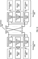
- a gNB such as gNBs 160 in FIG. 1B , may be split in two parts: a central unit (gNB-CU), and one or more distributed units (gNB-DU).
- a gNB-CU may be coupled to one or more gNB-DUs using an F1 interface.
- the gNB-CU may comprise the RRC, the PDCP, and the SDAP.
- a gNB-DU may comprise the RLC, the MAC, and the PHY.
- This operation produces Discrete Fourier Transform (DFT)-precoded OFDM symbols and may be used by UEs in the uplink to reduce the peak to average power ratio (PAPR).
- DFT Discrete Fourier Transform
- PAPR peak to average power ratio
- Inverse processing may be performed on the OFDM symbol at a receiver using an FFT block to recover the data mapped to the source symbols.
- FIG. 7 illustrates an example configuration of an NR frame into which OFDM symbols are grouped.
- An NR frame may be identified by a system frame number (SFN).
- the SFN may repeat with a period of 1024 frames.
- one NR frame may be 10 milliseconds (ms) in duration and may include 10 subframes that are 1 ms in duration.
- a subframe may be divided into slots that include, for example, 14 OFDM symbols per slot.
- the duration of a slot may depend on the numerology used for the OFDM symbols of the slot.
- a flexible numerology is supported to accommodate different cell deployments (e.g., cells with carrier frequencies below 1 GHz up to cells with carrier frequencies in the mm-wave range).
- a numerology may be defined in terms of subcarrier spacing and cyclic prefix duration.
- subcarrier spacings may be scaled up by powers of two from a baseline subcarrier spacing of 15 kHz
- cyclic prefix durations may be scaled down by powers of two from a baseline cyclic prefix duration of 4.7 ⁇ s.
- NR defines numerologies with the following subcarrier spacing/cyclic prefix duration combinations: 15 kHz/4.7 ⁇ s; 30 kHz/2.3 ⁇ s; 60 kHz/1.2 ⁇ s; 120 kHz/0.59 ⁇ s; and 240 kHz/0.29 ⁇ s.
- a slot may have a fixed number of OFDM symbols (e.g., 14 OFDM symbols).
- a numerology with a higher subcarrier spacing has a shorter slot duration and, correspondingly, more slots per subframe.
- FIG. 7 illustrates this numerology-dependent slot duration and slots-per-subframe transmission structure (the numerology with a subcarrier spacing of 240 kHz is not shown in FIG. 7 for ease of illustration).
- a subframe in NR may be used as a numerology-independent time reference, while a slot may be used as the unit upon which uplink and downlink transmissions are scheduled.
- scheduling in NR may be decoupled from the slot duration and start at any OFDM symbol and last for as many symbols as needed for a transmission. These partial slot transmissions may be referred to as mini-slot or subslot transmissions.
- FIG. 8 illustrates an example configuration of a slot in the time and frequency domain for an NR carrier.
- the slot includes resource elements (REs) and resource blocks (RBs).
- An RE is the smallest physical resource in NR.
- An RE spans one OFDM symbol in the time domain by one subcarrier in the frequency domain as shown in FIG. 8 .
- An RB spans twelve consecutive REs in the frequency domain as shown in FIG. 8 .
- Such a limitation may limit the NR carrier to 50, 100, 200, and 400 MHz for subcarrier spacings of 15, 30, 60, and 120 kHz, respectively, where the 400 MHz bandwidth may be set based on a 400 MHz per carrier bandwidth limit.
- a BS may configure a UE with one or more resource sets for one or more PUCCH transmissions.
- a UE may receive downlink receptions (e.g., PDCCH or PDSCH) in a downlink BWP according to a configured numerology (e.g., subcarrier spacing and cyclic prefix duration) for the downlink BWP.
- the UE may transmit uplink transmissions (e.g., PUCCH or PUSCH) in an uplink BWP according to a configured numerology (e.g., subcarrier spacing and cyclic prefix length for the uplink BWP).
- One or more BWP indicator fields may be provided in Downlink Control Information (DCI).
- DCI Downlink Control Information
- a value of a BWP indicator field may indicate which BWP in a set of configured BWPs is an active downlink BWP for one or more downlink receptions.
- the value of the one or more BWP indicator fields may indicate an active uplink BWP for one or more uplink transmissions.
- a base station may semi-statically configure a UE with a default downlink BWP within a set of configured downlink BWPs associated with a PCell. If the base station does not provide the default downlink BWP to the UE, the default downlink BWP may be an initial active downlink BWP. The UE may determine which BWP is the initial active downlink BWP based on a CORESET configuration obtained using the PBCH.
- a base station may configure a UE with a BWP inactivity timer value for a PCell.
- the UE may start or restart a BWP inactivity timer at any appropriate time.
- the UE may start or restart the BWP inactivity timer ( a ) when the UE detects a DCI indicating an active downlink BWP other than a default downlink BWP for a paired spectra operation; or ( b ) when a UE detects a DCI indicating an active downlink BWP or active uplink BWP other than a default downlink BWP or uplink BWP for an unpaired spectra operation.
- the UE may run the BWP inactivity timer toward expiration (for example, increment from zero to the BWP inactivity timer value, or decrement from the BWP inactivity timer value to zero).
- the UE may switch from the active downlink BWP to the default downlink BWP.
- a base station may semi-statically configure a UE with one or more BWPs.
- a UE may switch an active BWP from a first BWP to a second BWP in response to receiving a DCI indicating the second BWP as an active BWP and/or in response to an expiry of the BWP inactivity timer (e.g., if the second BWP is the default BWP).
- Downlink and uplink BWP switching may be performed independently in paired spectra. In unpaired spectra, downlink and uplink BWP switching may be performed simultaneously. Switching between configured BWPs may occur based on RRC signaling, DCI, expiration of a BWP inactivity timer, and/or an initiation of random access.
- FIG. 9 illustrates an example of bandwidth adaptation using three configured BWPs for an NR carrier.
- a UE configured with the three BWPs may switch from one BWP to another BWP at a switching point.
- the BWPs include: a BWP 902 with a bandwidth of 40 MHz and a subcarrier spacing of 15 kHz; a BWP 904 with a bandwidth of 10 MHz and a subcarrier spacing of 15 kHz; and a BWP 906 with a bandwidth of 20 MHz and a subcarrier spacing of 60 kHz.
- the BWP 902 may be an initial active BWP
- the BWP 904 may be a default BWP.
- the UE may switch between BWPs at switching points.
- the UE may switch from the BWP 902 to the BWP 904 at a switching point 908.
- the switching at the switching point 908 may occur for any suitable reason, for example, in response to an expiry of a BWP inactivity timer (indicating switching to the default BWP) and/or in response to receiving a DCI indicating BWP 904 as the active BWP.
- the UE may switch at a switching point 910 from active BWP 904 to BWP 906 in response receiving a DCI indicating BWP 906 as the active BWP.
- the UE may switch at a switching point 912 from active BWP 906 to BWP 904 in response to an expiry of a BWP inactivity timer and/or in response receiving a DCI indicating BWP 904 as the active BWP.
- the UE may switch at a switching point 914 from active BWP 904 to BWP 902 in response receiving a DCI indicating BWP 902 as the active BWP.
- CA carrier aggregation
- the aggregated carriers in CA may be referred to as component carriers (CCs).
- CCs component carriers
- the CCs may have three configurations in the frequency domain.
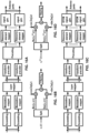
- FIG. 10A illustrates the three CA configurations with two CCs.
- the two CCs are aggregated in the same frequency band (frequency band A) and are located directly adjacent to each other within the frequency band.
- the two CCs are aggregated in the same frequency band (frequency band A) and are separated in the frequency band by a gap.
- the two CCs are located in frequency bands (frequency band A and frequency band B).
- up to 32 CCs may be aggregated.
- the aggregated CCs may have the same or different bandwidths, subcarrier spacing, and/or duplexing schemes (TDD or FDD).
- a serving cell for a UE using CA may have a downlink CC.
- one or more uplink CCs may be optionally configured for a serving cell.
- the ability to aggregate more downlink carriers than uplink carriers may be useful, for example, when the UE has more data traffic in the downlink than in the uplink.
- one of the aggregated cells for a UE may be referred to as a primary cell (PCell).
- the PCell may be the serving cell that the UE initially connects to at RRC connection establishment, reestablishment, and/or handover.
- the PCell may provide the UE with NAS mobility information and the security input.
- UEs may have different PCells.
- the carrier corresponding to the PCell may be referred to as the downlink primary CC (DL PCC).
- the carrier corresponding to the PCell may be referred to as the uplink primary CC (UL PCC).
- SCells secondary cells
- the SCells may be configured after the PCell is configured for the UE.
- an SCell may be configured through an RRC Connection Reconfiguration procedure.
- the carrier corresponding to an SCell may be referred to as a downlink secondary CC (DL SCC).
- DL SCC downlink secondary CC
- UL SCC uplink secondary CC
- One or more other uplink CCs may be configured as a primary Scell (PSCell) 1061, an SCell 1062, and an SCell 1063.
- Uplink control information (UCI) related to the downlink CCs of the PUCCH group 1010 shown as UCI 1031, UCI 1032, and UCI 1033, may be transmitted in the uplink of the PCell 1021.
- Uplink control information (UCI) related to the downlink CCs of the PUCCH group 1050, shown as UCI 1071, UCI 1072, and UCI 1073, may be transmitted in the uplink of the PSCell 1061.
- a cell comprising a downlink carrier and optionally an uplink carrier, may be assigned with a physical cell ID and a cell index.
- the physical cell ID or the cell index may identify a downlink carrier and/or an uplink carrier of the cell, for example, depending on the context in which the physical cell ID is used.
- a physical cell ID may be determined using a synchronization signal transmitted on a downlink component carrier.
- a cell index may be determined using RRC messages.
- a physical cell ID may be referred to as a carrier ID
- a cell index may be referred to as a carrier index.
- the disclosure may mean the first physical cell ID is for a cell comprising the first downlink carrier.
- the same/similar concept may apply to, for example, a carrier activation.
- the disclosure indicates that a first carrier is activated
- the specification may mean that a cell comprising the first carrier is activated.
- a multi-carrier nature of a PHY may be exposed to a MAC.
- a HARQ entity may operate on a serving cell.
- a transport block may be generated per assignment/grant per serving cell.
- a transport block and potential HARQ retransmissions of the transport block may be mapped to a serving cell.
- a base station may transmit (e.g., unicast, multicast, and/or broadcast) one or more Reference Signals (RSs) to a UE (e.g., PSS, SSS, CSI-RS, DMRS, and/or PT-RS, as shown in FIG. 5A ).
- RSs Reference Signals
- the UE may transmit one or more RSs to the base station (e.g., DMRS, PT-RS, and/or SRS, as shown in FIG. 5B ).
- the PSS and the SSS may be transmitted by the base station and used by the UE to synchronize the UE to the base station.
- the PSS and the SSS may be provided in a synchronization signal (SS) / physical broadcast channel (PBCH) block that includes the PSS, the SSS, and the PBCH.
- the base station may periodically transmit a burst of SS/PBCH blocks.
- FIG. 11A illustrates an example of an SS/PBCH block's structure and location.
- a burst of SS/PBCH blocks may include one or more SS/PBCH blocks (e.g., 4 SS/PBCH blocks, as shown in FIG. 11A ). Bursts may be transmitted periodically (e.g., every 2 frames or 20 ms). A burst may be restricted to a half-frame (e.g., a first half-frame having a duration of 5 ms). It will be understood that FIG.
- the location of the SS/PBCH block in the time and frequency domains may not be known to the UE (e.g., if the UE is searching for the cell).
- the UE may monitor a carrier for the PSS. For example, the UE may monitor a frequency location within the carrier. If the PSS is not found after a certain duration (e.g., 20 ms), the UE may search for the PSS at a different frequency location within the carrier, as indicated by a synchronization raster. If the PSS is found at a location in the time and frequency domains, the UE may determine, based on a known structure of the SS/PBCH block, the locations of the SSS and the PBCH, respectively.
- the SS/PBCH block may be used by the UE to determine one or more parameters of the cell. For example, the UE may determine a physical cell identifier (PCI) of the cell based on the sequences of the PSS and the SSS, respectively. The UE may determine a location of a frame boundary of the cell based on the location of the SS/PBCH block. For example, the SS/PBCH block may indicate that it has been transmitted in accordance with a transmission pattern, wherein a SS/PBCH block in the transmission pattern is a known distance from the frame boundary.
- PCI physical cell identifier
- the PBCH may use a QPSK modulation and may use forward error correction (FEC).
- FEC forward error correction
- the FEC may use polar coding.
- One or more symbols spanned by the PBCH may carry one or more DMRSs for demodulation of the PBCH.
- the PBCH may include an indication of a current system frame number (SFN) of the cell and/or a SS/PBCH block timing index. These parameters may facilitate time synchronization of the UE to the base station.
- the PBCH may include a master information block (MIB) used to provide the UE with one or more parameters.
- the MIB may be used by the UE to locate remaining minimum system information (RMSI) associated with the cell.
- the RMSI may include a System Information Block Type 1 (SIB1).
- the SIB1 may contain information needed by the UE to access the cell.
- the UE may use one or more parameters of the MIB to monitor PDCCH, which may be used to schedule PDSCH.
- the PDSCH may include the SIB1.
- the SIB1 may be decoded using parameters provided in the MIB.
- the PBCH may indicate an absence of SIB1. Based on the PBCH indicating the absence of SIB1, the UE may be pointed to a frequency. The UE may search for an SS/PBCH block at the frequency to which the UE is pointed.
- the UE may assume that one or more SS/PBCH blocks transmitted with a same SS/PBCH block index are quasi co-located (QCLed) (e.g., having the same/similar Doppler spread, Doppler shift, average gain, average delay, and/or spatial Rx parameters).
- QCL quasi co-located
- SS/PBCH blocks may be transmitted in spatial directions (e.g., using different beams that span a coverage area of the cell).
- a first SS/PBCH block may be transmitted in a first spatial direction using a first beam
- a second SS/PBCH block may be transmitted in a second spatial direction using a second beam.
- a base station may transmit a plurality of SS/PBCH blocks.
- a first PCI of a first SS/PBCH block of the plurality of SS/PBCH blocks may be different from a second PCI of a second SS/PBCH block of the plurality of SS/PBCH blocks.
- the PCIs of SS/PBCH blocks transmitted in different frequency locations may be different or the same.
- the CSI-RS may be transmitted by the base station and used by the UE to acquire channel state information (CSI).
- the base station may configure the UE with one or more CSI-RSs for channel estimation or any other suitable purpose.
- the base station may configure a UE with one or more of the same/similar CSI-RSs.
- the UE may measure the one or more CSI-RSs.
- the UE may estimate a downlink channel state and/or generate a CSI report based on the measuring of the one or more downlink CSI-RSs.
- the UE may provide the CSI report to the base station.
- the base station may use feedback provided by the UE (e.g., the estimated downlink channel state) to perform link adaptation.
- the CSI-RS configuration may comprise one or more parameters indicating, for example, up to 32 antenna ports.
- the UE may be configured to employ the same OFDM symbols for a downlink CSI-RS and a control resource set (CORESET) when the downlink CSI-RS and CORESET are spatially QCLed and resource elements associated with the downlink CSI-RS are outside of the physical resource blocks (PRBs) configured for the CORESET.
- the UE may be configured to employ the same OFDM symbols for downlink CSI-RS and SS/PBCH blocks when the downlink CSI-RS and SS/PBCH blocks are spatially QCLed and resource elements associated with the downlink CSI-RS are outside of PRBs configured for the SS/PBCH blocks.
- Downlink DMRSs may be transmitted by a base station and used by a UE for channel estimation.
- the downlink DMRS may be used for coherent demodulation of one or more downlink physical channels (e.g., PDSCH).
- An NR network may support one or more variable and/or configurable DMRS patterns for data demodulation.
- At least one downlink DMRS configuration may support a front-loaded DMRS pattern.
- a front-loaded DMRS may be mapped over one or more OFDM symbols (e.g., one or two adjacent OFDM symbols).
- a base station may semi-statically configure the UE with a number (e.g. a maximum number) of front-loaded DMRS symbols for PDSCH.
- a DMRS configuration may support one or more DMRS ports.
- a DMRS configuration may support up to eight orthogonal downlink DMRS ports per UE.
- a DMRS configuration may support up to 4 orthogonal downlink DMRS ports per UE.
- a radio network may support (e.g., at least for CP-OFDM) a common DMRS structure for downlink and uplink, wherein a DMRS location, a DMRS pattern, and/or a scrambling sequence may be the same or different.
- the base station may transmit a downlink DMRS and a corresponding PDSCH using the same precoding matrix.
- the UE may use the one or more downlink DMRSs for coherent demodulation/channel estimation of the PDSCH.
- a transmitter may use a precoder matrices for a part of a transmission bandwidth.
- the transmitter may use a first precoder matrix for a first bandwidth and a second precoder matrix for a second bandwidth.
- the first precoder matrix and the second precoder matrix may be different based on the first bandwidth being different from the second bandwidth.
- the UE may assume that a same precoding matrix is used across a set of PRBs.
- the set of PRBs may be denoted as a precoding resource block group (PRG).
- PRG precoding resource block group
- a PDSCH may comprise one or more layers.
- the UE may assume that at least one symbol with DMRS is present on a layer of the one or more layers of the PDSCH.
- a higher layer may configure up to 3 DMRSs for the PDSCH.
- Downlink PT-RS may be transmitted by a base station and used by a UE for phase-noise compensation. Whether a downlink PT-RS is present or not may depend on an RRC configuration. The presence and/or pattern of the downlink PT-RS may be configured on a UE-specific basis using a combination of RRC signaling and/or an association with one or more parameters employed for other purposes (e.g., modulation and coding scheme (MCS)), which may be indicated by DCI. When configured, a dynamic presence of a downlink PT-RS may be associated with one or more DCI parameters comprising at least MCS.
- An NR network may support a plurality of PT-RS densities defined in the time and/or frequency domains.
- a frequency domain density may be associated with at least one configuration of a scheduled bandwidth.
- the UE may assume a same precoding for a DMRS port and a PT-RS port.
- a number of PT-RS ports may be fewer than a number of DMRS ports in a scheduled resource.
- Downlink PT-RS may be confined in the scheduled time/frequency duration for the UE.
- Downlink PT-RS may be transmitted on symbols to facilitate phase tracking at the receiver.
- the UE may transmit an uplink DMRS to a base station for channel estimation.
- the base station may use the uplink DMRS for coherent demodulation of one or more uplink physical channels.
- the UE may transmit an uplink DMRS with a PUSCH and/or a PUCCH.
- the uplink DM-RS may span a range of frequencies that is similar to a range of frequencies associated with the corresponding physical channel.
- the base station may configure the UE with one or more uplink DMRS configurations. At least one DMRS configuration may support a front-loaded DMRS pattern.
- the front-loaded DMRS may be mapped over one or more OFDM symbols (e.g., one or two adjacent OFDM symbols).
- One or more uplink DMRSs may be configured to transmit at one or more symbols of a PUSCH and/or a PUCCH.
- the base station may semi-statically configure the UE with a number (e.g. maximum number) of front-loaded DMRS symbols for the PUSCH and/or the PUCCH, which the UE may use to schedule a single-symbol DMRS and/or a double-symbol DMRS.
- An NR network may support (e.g., for cyclic prefix orthogonal frequency division multiplexing (CP-OFDM)) a common DMRS structure for downlink and uplink, wherein a DMRS location, a DMRS pattern, and/or a scrambling sequence for the DMRS may be the same or different.
- CP-OFDM cyclic prefix orthogonal frequency division multiplexing
- a PUSCH may comprise one or more layers, and the UE may transmit at least one symbol with DMRS present on a layer of the one or more layers of the PUSCH.
- a higher layer may configure up to three DMRSs for the PUSCH.
- Uplink PT-RS (which may be used by a base station for phase tracking and/or phase-noise compensation) may or may not be present depending on an RRC configuration of the UE.
- the presence and/or pattern of uplink PT-RS may be configured on a UE-specific basis by a combination of RRC signaling and/or one or more parameters employed for other purposes (e.g., Modulation and Coding Scheme (MCS)), which may be indicated by DCI.
- MCS Modulation and Coding Scheme
- a dynamic presence of uplink PT-RS may be associated with one or more DCI parameters comprising at least MCS.
- a radio network may support a plurality of uplink PT-RS densities defined in time/frequency domain.
- a frequency domain density may be associated with at least one configuration of a scheduled bandwidth.
- the UE may assume a same precoding for a DMRS port and a PT-RS port.
- a number of PT-RS ports may be fewer than a number of DMRS ports in a scheduled resource.
- uplink PT-RS may be confined in the scheduled time/frequency duration for the UE.
- SRS may be transmitted by a UE to a base station for channel state estimation to support uplink channel dependent scheduling and/or link adaptation.
- SRS transmitted by the UE may allow a base station to estimate an uplink channel state at one or more frequencies.
- a scheduler at the base station may employ the estimated uplink channel state to assign one or more resource blocks for an uplink PUSCH transmission from the UE.
- the base station may semi-statically configure the UE with one or more SRS resource sets. For an SRS resource set, the base station may configure the UE with one or more SRS resources.
- An SRS resource set applicability may be configured by a higher layer (e.g., RRC) parameter.
- the base station may semi-statically configure the UE with one or more SRS configuration parameters indicating at least one of following: a SRS resource configuration identifier; a number of SRS ports; time domain behavior of an SRS resource configuration (e.g., an indication of periodic, semi-persistent, or aperiodic SRS); slot, mini-slot, and/or subframe level periodicity; offset for a periodic and/or an aperiodic SRS resource; a number of OFDM symbols in an SRS resource; a starting OFDM symbol of an SRS resource; an SRS bandwidth; a frequency hopping bandwidth; a cyclic shift; and/or an SRS sequence ID.
- SRS resource configuration identifier e.g., an indication of periodic, semi-persistent, or aperiodic SRS
- slot, mini-slot, and/or subframe level periodicity e.g., an indication of periodic, semi-persistent, or aperiodic SRS
- An antenna port is defined such that the channel over which a symbol on the antenna port is conveyed can be inferred from the channel over which another symbol on the same antenna port is conveyed. If a first symbol and a second symbol are transmitted on the same antenna port, the receiver may infer the channel (e.g., fading gain, multipath delay, and/or the like) for conveying the second symbol on the antenna port, from the channel for conveying the first symbol on the antenna port.
- a first antenna port and a second antenna port may be referred to as quasi co-located (QCLed) if one or more large-scale properties of the channel over which a first symbol on the first antenna port is conveyed may be inferred from the channel over which a second symbol on a second antenna port is conveyed.
- the one or more large-scale properties may comprise at least one of: a delay spread; a Doppler spread; a Doppler shift; an average gain; an average delay; and/or spatial Receiving (Rx) parameters.
- Beam management may comprise beam measurement, beam selection, and beam indication.
- a beam may be associated with one or more reference signals.
- a beam may be identified by one or more beamformed reference signals.
- the UE may perform downlink beam measurement based on downlink reference signals (e.g., a channel state information reference signal (CSI-RS)) and generate a beam measurement report.
- CSI-RS channel state information reference signal
- the UE may perform the downlink beam measurement procedure after an RRC connection is set up with a base station.
- FIG. 11B illustrates an example of channel state information reference signals (CSI-RSs) that are mapped in the time and frequency domains.
- CSI-RSs channel state information reference signals
- a square shown in FIG. 11B may span a resource block (RB) within a bandwidth of a cell.
- a base station may transmit one or more RRC messages comprising CSI-RS resource configuration parameters indicating one or more CSI-RSs.
- the three beams illustrated in FIG. 11B may be configured for a UE in a UE-specific configuration. Three beams are illustrated in FIG. 11B (beam #1, beam #2, and beam #3), more or fewer beams may be configured.
- Beam #1 may be allocated with CSI-RS 1101 that may be transmitted in one or more subcarriers in an RB of a first symbol.
- Beam #2 may be allocated with CSI-RS 1102 that may be transmitted in one or more subcarriers in an RB of a second symbol.
- Beam #3 may be allocated with CSI-RS 1103 that may be transmitted in one or more subcarriers in an RB of a third symbol.
- a first tci-PresenceInDCI of the first coreset may same as a second tci-PresenceInDCI of the second coreset.
- a first rb-Offset of the first coreset may be same as a second rb-Offset of the second coreset.
- a parameter to indicate enabling of the control channel repetition may be configured for the search space or for a coreset associated with the search space or a DCI format monitored via the search space.
- a duration of the search space may be used to determine the one or more monitoring occasions within the monitoring periodicity. For example, when the monitoring periodicity is larger than a slot, the wireless device may determine the one or more monitoring occasions based on the monitoring periodicity and the duration. For example, when the monitoring periodicity is P slots and the duration is D, the wireless device may determine a first monitoring occasion of the one or more monitoring occasions based on the monitoringSlotPeriodicityAndOffset. The wireless device may determine a second monitoring occasion of the one or more monitoring occasions as a next slot of the first monitoring occasion.
- a base station may transmit a first DCI/PDCCH via a first monitoring occasion of the one or more monitoring occasions.
- the base station may transmit a second DCI/PDCCH via a second monitoring occasions of the one or more monitoring occasions.
- the first DCI/PDCCH and the second DCI/PDCCH may indicate same resource(s) for a transport block.
- a first content of the first DCI/PDCCH may be same as or different from a second content of the second DCI/PDCCH.
- the wireless device may attempt to decode the first DCI/PDCCH independently from the second DCI/PDCCH. The wireless device may not assume that the base station may transmit the first DCI/PDCCH and the second DCI/PDCCH.
- the base station may transmit one or more DCIs/PDCCHs over the one or more monitoring occasions.
- the base station may transmit a single DCI/PDCCH over the one or more monitoring occasions.
- the base station may transmit a DCI/PDCCH in each monitoring occasion.
- the base station may transmit any number of repeated DCIs/PDCCHs over the one or more monitoring occasions.
- the wireless device may attempt to decode a second candidate aggregating the candidate and another candidate from 2nd monitoring occasion of the one or more monitoring occasions.
- the wireless device may attempt to decode a fourth candidate aggregating each candidate of each monitoring occasion of the one or more monitoring occasions.
- the wireless device may aggregate candidates from the one or more monitoring occasions where a starting CCE index of a candidate of the candidates is same or the wireless device may determine candidates based on a rule. For example, the wireless device may determine candidates of same frequency resources in each monitoring occasion. For example, the wireless device may determine candidates of same REGs (or same REG indexes) in each monitoring occasion.
- a wireless device may determine each list of candidates via each monitoring occasion of one or more monitoring occasions within a monitoring periodicity of a search space.
- the wireless device may determine a list of candidates across the one or more monitoring occasions based on each list of candidates.
- the list of candidates may comprise one or more candidates of an aggregation level. For example, the wireless device may determine a first list of candidates of a first aggregation level 2 * L based on two candidates over two monitoring occasions of aggregation level L or four candidates over four monitoring occasions of aggregation level L/2.
- a base station may indicate four monitoring occasions in a monitoring periodicity indexed from 1st to 4th monitoring occasion.
- a set of candidates for an aggregation level is assumed to be consistent across the four monitoring occasions. For example, a first candidate of an aggregation level 2 may start in 3rd CCE and a second candidate of the aggregation level 2 may start in 5th CCE.
- a first candidate of an aggregation level 4 may start in N_CCE (e.g., a number of CCEs) - 8th CCE and a second candidate of the aggregation level 4 may start in N_CCE - 4th CCE.
- the wireless device may determine a list of candidates with an aggregation level 8 by combining/aggregating four candidates (one candidate from one monitoring occasion each) of the aggregation level 2 and/or by combining/aggregating two candidates (one candidate from one monitoring occasion each) of the aggregation level 4.
- the wireless device may not aggregate candidates wherein the candidates may not comprise a candidate from the first monitoring occasion (or 1st monitoring occasion, an earliest monitoring occasion in a monitoring periodicity).
- the wireless device may determine possible aggregation levels and/or candidates by aggregating candidates from 1st monitoring occasion, 1st + 2nd monitoring occasions, 1st + 2nd + 3rd + 4th monitoring occasions, 1st+2nd+3rd+4th+5th-6th+7th+8th, ... , and so on.
- the wireless device may determine a list of candidates for an aggregation level based on a hashing function applied in each slot. Same candidates may be mapped when a first monitoring occasion and a second monitoring occasion reside in a same slot. Otherwise, different candidates may be determined.
- a base station may transmit a DCI over a candidate of the across the one or more monitoring occasions.
- a base station may transmit one or more messages comprising configuration parameters.
- the configuration parameters may comprise/indicate a search space group for a control channel repetition.
- the search space group may comprise one or more search spaces.
- the search group may comprise a first search space of a first carrier and a second search space of a second carrier.
- the search space group may comprise a first search space of a first BWP of a cell and a second search space of a second BWP of the cell.
- the search space group may comprise a first search space of first BWP of a first cell and a second search space of a second BWP of a second cell.
- the configuration parameters may indicate one or more search space groups.
- a search space group of the one or more search space groups may be associated/configured with one or more DCI formats.
- a wireless device may determine a search space group based on one or more search spaces configured/associated with the BWP of the cell, where each search space of the one or more search spaces may be configured to monitor a DCI format of the one or more DCI formats.
- the one or more DCI formats may comprise a DCI format 1_1 and a DCI format 0_1.
- the one or more DCI formats may comprise a DCI format 0_0 and a DCI format 1_0.
- the one or more DCI formats may comprise a DCI format 1_2 and a DCI format 0_2.
- the one or more DCI formats may comprise a DCI format 3_0 and a DCI format 3_1.
- the one or more DCI formats may comprise downlink/uplink DCIs of non-fallback DCIs.
- the one or more DCI formats may comprise downlink/uplink DCIs of fallback DCIs.
- the one or more DCI formats may comprise DCI format(s) of sidelink DCIs.
- the wireless device may determine a search space candidate over the one or more search space of the search space group in a similar manner addressed for a control repetition based on a plurality of coresets.
- the wireless device may determine one or more monitoring occasions in a slot based on the one or more search spaces. For example, in a slot n, the wireless device may determine one or more first monitoring occasions based on a first search space of the one or more search spaces.
- the wireless device may determine, in the slot n, one or more second monitoring occasions based on a second search space of the one or more search spaces.
- the wireless device may monitor the one or more first monitoring occasions and the one or more second monitoring occasions in the slot n.
- the wireless device may not expect to have overlap between a monitoring occasion of a search space of the one or more search spaces and a second monitoring occasion of a second search space of the one or more search spaces in a time domain.
- the wireless device may monitor one or more repeated DCIs based on the DCI format via the one or more monitoring occasions in the slot.
- the one or more repeated DCIs may be transmitted, by the base station, via one or more PDCCHs, where each PDCCH may carry/transmit each DCI.
- Each DCI of the one or more repeated DCIs may have same content or different content.
- the wireless device may aggregate the one or more repeated DCIs when each DCI may have same content.
- the one or more repeated DCIs may be transmitted via a PDCCH, where the PDCCH may be transmitted over one or more search space candidates of the one or more search spaces.
- a DCI may be transmitted repeatedly via one or more PDCCHs, where each PDCCH may carrier/transmit the DCI repeatedly.
- a base station may associate a plurality of TCI states with a coreset as active TCI states.
- FIG. 22 illustrates an example of a coreset being associated with a plurality of TCI states as active TCI states as per an aspect of an embodiment of the present disclosure.
- the base station may indicate a plurality of monitoring occasions within a slot or in a monitoring periodicity for a control channel repetition.
- a wireless device may monitor a first monitoring occasion based on a first TCI state of the plurality of TCI states.
- the wireless device may monitor a second monitoring occasion based on a second TCI state of the plurality of TCI states.
- the base station may indicate a pattern to switch between the plurality of TCI states.
- configuration parameters of a search space associated with the coreset may comprise/indicate enabling a control channel repetition.
- the configuration parameters may comprise/indicate enabling a TCI switching or enabling the control channel repetition via a plurality of TCI states.
- the configuration parameters may comprise/indicate a switching pattern.
- the switching pattern may be an alternating between a first TCI state of the plurality of TCI states and a second TCI state of the plurality of TCI states in each monitoring occasion of one or more monitoring occasions within a monitoring periodicity or a slot or within a few slots (e.g., between a monitoring periodicity configured by monitoringSlotPeriodicity AndOffset parameter of the search space).
- the switching pattern may be a half-half between the first TCI state and the second TCI state.
- a number of the one or more monitoring occasions is K.
- the wireless device may monitor first floor (K/2) monitoring occasion(s) based on the first TCI state.
- the wireless device may monitor remaining monitoring occasion(s) based on the second TCI state within the monitoring periodicity.
- the switching pattern may be a bitmap to indicate a TCI state in each monitoring occasion of the one or more monitoring occasions.
- FIG. 23 illustrates an example of a MAC CE format (e.g., TCI State Indication for UE-specific PDCCH MAC CE, Enhanced TCI State Indication for UE-specific PDCCH MAC CE) indicating/activating/updating/selecting one or more TCI states (e.g., TCI state 1 and TCI state 2) for a coreset of a serving cell.
- the base station may indicate, in the MAC CE format, one or more TCI state indexes (e.g., TCI state ID 1 and TCI state ID 2) to activate the one or more TCI states for the coreset (indicated by a coreset ID).
- the one or more TCI state indexes may indicate/identify the one or more TCI states.
- Each TCI state index of the one or more TCI state indexes may indicate/identify a respective TCI state of the one or more TCI states.
- the MAC CE format may comprise one or more fields.
- a first field of the one or more fields may indicate/comprise a serving cell index (e.g., Serving Cell ID provided by a higher layer parameter ServCellIndex or indicated by one or more configuration parameters) of/identifying/indicating the serving cell.
- a second field of the one or more fields may indicate/comprise a coreset index (e.g., Coreset ID) of/identifying/indicating the coreset of the serving cell.
- a third field of the one or more fields may indicate/comprise a first TCI state index (e.g., TCI state ID 1) of/identifying/indicating a first TCI state.
- the one or more TCI states may comprise the first TCI state.
- a fourth field (e.g., R) of the one or more fields may be a reserved field.
- a fifth field of the one or more fields may indicate/comprise a second TCI state index (e.g., TCI state ID 2) of/identifying/indicating a second TCI state.
- the one or more fields of the MAC CE format may comprise the second TCI state index based on a value of the fourth field (e.g., R).
- the MAC CE format may not comprise the second TCI state index (e.g., the fifth field may be a reserved field).
- the MAC CE format may comprise the second TCI state index.
- the one or more TCI states may comprise the second TCI state.
- the MAC CE format may be an activation command.
- the configuration parameters may indicate the first TCI state index for the first TCI state.
- the configuration parameters may indicate the second TCI state index for the second TCI state.
- the configuration parameters may indicate the coreset index for the coreset.
- the configuration parameters may indicate the serving cell index for the serving cell.
- the configuration parameters may indicate the one or more TCI state indexes for the one or more TCI states.
- the one or more TCI states may comprise the first TCI state and the second TCI state.
- the one or more TCI state indexes may comprise the first TCI state index and the second TCI state index.
- a wireless device may receive one or more messages.
- the wireless device may receive the one or more messages from a base station.
- the one or more messages may comprise one or more configuration parameters.
- the one or more configuration parameters may be RRC configuration parameter(s).
- the one or more configuration parameters may be RRC reconfiguration parameter(s).
- the one or more configuration parameters may be for a cell.
- at least one configuration parameter of the one or more configuration parameters may be for a cell.
- the cell may be a primary cell (PCell).
- the cell may be a secondary cell (SCell).
- the cell may be a secondary cell configured with PUCCH (e.g., PUCCH SCell).
- the cell may be an unlicensed cell, e.g., operating in an unlicensed band.
- the cell may be a licensed cell, e.g., operating in a licensed band.
- the cell may operate in a first frequency range (FR1).
- the FR1 may, for example, comprise frequency bands below 6 GHz.
- the cell may operate in a second frequency range (FR2).
- the FR2 may, for example, comprise frequency bands from 24 GHz to 52.6 GHz.
- the wireless device may perform uplink transmissions (e.g., PUSCH, PUCCH, SRS) via the cell in a first time and in a first frequency.
- the wireless device may perform downlink receptions (e.g., PDCCH, PDSCH) via the cell in a second time and in a second frequency.
- the cell may operate in a time-division duplex (TDD) mode.
- TDD time-division duplex
- the first frequency and the second frequency may be the same.
- the first time and the second time may be different.
- the cell may operate in a frequency-division duplex (FDD) mode.
- FDD mode frequency-division duplex
- the FDD mode the first frequency and the second frequency may be different.
- the first time and the second time may be the same.
- the wireless device may be in an RRC connected mode.
- the wireless device may be in an RRC idle mode.
- the wireless device may be in an RRC inactive mode.
- the cell may comprise a plurality of BWPs.
- the plurality of BWPs may comprise one or more uplink BWPs comprising an uplink BWP of the cell.
- the plurality of BWPs may comprise one or more downlink BWPs comprising a downlink BWP of the cell.
- a BWP of the plurality of BWPs may be in one of an active state and an inactive state.
- the wireless device in the active state of a downlink BWP of the one or more downlink BWPs, the wireless device may monitor a downlink channel/signal (e.g., PDCCH, DCI, CSI-RS, PDSCH) on/for/via the downlink BWP.
- a downlink channel/signal e.g., PDCCH, DCI, CSI-RS, PDSCH
- the wireless device may receive a PDSCH on/via/for the downlink BWP.
- the wireless device in the inactive state of a downlink BWP of the one or more downlink BWPs, may not monitor a downlink channel/signal (e.g., PDCCH, DCI, CSI-RS, PDSCH) on/via/for the downlink BWP.
- a downlink channel/signal e.g., PDCCH, DCI, CSI-RS, PDSCH
- the wireless device may stop monitoring (or receiving) a downlink channel/signal (e.g., PDCCH, DCI, CSI-RS, PDSCH) on/via/for the downlink BWP.
- the wireless device in the inactive state of a downlink BWP of the one or more downlink BWPs, may not receive a PDSCH on/via/for the downlink BWP. In the inactive state of a downlink BWP of the one or more downlink BWPs, the wireless device may stop receiving a PDSCH on/via/for the downlink BWP.
- the wireless device may transmit an uplink signal/channel (e.g., PUCCH, preamble, PUSCH, PRACH, SRS, etc.) on/via the uplink BWP.
- the wireless device in the inactive state of an uplink BWP of the one or more uplink BWPs, may not transmit an uplink signal/channel (e.g., PUCCH, preamble, PUSCH, PRACH, SRS, etc.) on/via the uplink BWP.
- the wireless device may activate the downlink BWP of the one or more downlink BWPs of the cell.
- the activating the downlink BWP may comprise that the wireless device sets (or switches to) the downlink BWP as an active downlink BWP of the cell.
- the activating the downlink BWP may comprise that the wireless device sets the downlink BWP in the active state.
- the activating the downlink BWP may comprise switching the downlink BWP from the inactive state to the active state.
- the wireless device may activate the uplink BWP of the one or more uplink BWPs of the cell.
- the activating the uplink BWP may comprise that the wireless device sets (or switches to) the uplink BWP as an active uplink BWP of the cell.
- the activating the uplink BWP may comprise that the wireless device sets the uplink BWP in the active state.
- the activating the uplink BWP may comprise switching the uplink BWP from the inactive state to the active state.
- the one or more configuration parameters may be for the (active) downlink BWP of the cell. In an example, at least one configuration parameter of the one or more configuration parameters may be for the downlink BWP of the cell.
- the one or more configuration parameters may be for the (active) uplink BWP of the cell. In an example, at least one configuration parameter of the one or more configuration parameters may be for the uplink BWP of the cell.
- the one or more configuration parameters may indicate one or more coresets.
- the one or more configuration parameters may indicate the one or more coresets for the (active) downlink BWP of the cell.
- the (active) downlink BWP of the cell may comprise the one or more coresets.
- the one or more configuration parameters may indicate one or more coreset indexes (e.g., provided by a higher layer parameter ControlResourceSetId) for the one or more coresets.
- each coreset of the one or more coresets may be identified/indicated by a respective coreset index of the one or more coreset indexes.
- a first coreset of the one or more coresets may be identified by a first coreset index of the one or more coreset indexes.
- a second coreset of the one or more coresets may be identified by a second coreset index of the one or more coreset indexes.
- a coreset index may be a coreset identifier.
- the one or more configuration parameters may indicate a plurality of search space sets, e.g., for the downlink BWP of the cell (e.g., by a higher layer parameter SearchSpace). In an example, the one or more configuration parameters may indicate a plurality of search space sets, e.g., for the cell (e.g., by a higher layer parameter SearchSpace).
- the one or more configuration parameters may indicate search space set indexes/identifiers (e.g., provided by a higher layer parameter searchSpaceId) for the plurality of search space sets.
- each search space set of the plurality of search space sets may be identified by a respective search space set index of the search space set indexes.
- a first search space set of the plurality of search space sets may be identified by a first search space set index of the search space set indexes.
- a second search space set of the plurality of search space sets may be identified by a second search space set index of the search space set indexes.
- the one or more configuration parameters may indicate PDCCH monitoring periodicities (e.g., monitoringSlotPeriodicityAndOffset) for the plurality of search space sets.
- the one or more configuration parameters may indicate a respective PDCCH monitoring periodicity of the PDCCH monitoring periodicities (e.g., monitoringSlotPeriodicityAndOffset) for each search space set of the plurality of search space sets.
- the one or more configuration parameters may indicate a first PDCCH monitoring periodicity (e.g., 2 slots) of the PDCCH monitoring periodicities for a first search space set of the plurality of search space sets.
- the one or more configuration parameters may indicate a second PDCCH monitoring periodicity (e.g., 10 slots) of the PDCCH monitoring periodicities for a second search space set of the plurality of search space sets.
- each search space set of the plurality of search space sets may be associated with (or linked to or mapped to) a respective coreset of the one or more coresets.
- a search space set of the plurality of search space sets may be associated with (or linked to or mapped to) a coreset of the one or more coresets.
- the one or more configuration parameters may indicate the coreset (or a coreset index of the coreset) for the search space set (e.g., provided by a higher layer parameter controlResourceSetId in the higher layer parameter SearchSpace).
- the association (or the linkage or the mapping) may be one-to-one. The association being one-to-one may comprise the search space set associated with (or linked to) the coreset not being associated (or linked to) a second coreset that is different from the coreset.
- the one or more configuration parameters may indicate the one or more coreset indexes for the plurality of search space sets (e.g., provided by a higher layer parameter controlResourceSetId in the higher layer parameter SearchSpace).
- each search space set of the plurality of search space sets may be associated with (or linked to or mapped to) a coreset, of the one or more coresets, identified by a respective coreset index of the one or more coreset indexes.
- the one or more configuration parameters may indicate the first coreset index of the first coreset for the first search space set.
- the one or more configuration parameters may indicate the first coreset index of the first coreset in a first coreset index field (e.g., provided by a higher layer parameter controlResourceSetId in the higher layer parameter SearchSpace) of the first search space set.
- the first search space set may be associated with (or linked to) the first coreset.
- the one or more configuration parameters may indicate the first coreset index of the first coreset for the second search space set.
- the one or more configuration parameters may indicate the first coreset index of the first coreset in a second coreset index field (e.g., provided by a higher layer parameter controlResourceSetId in the higher layer parameter SearchSpace) of the second search space set.
- the second search space set may be associated with (or linked to) the first coreset.
- the one or more configuration parameters may indicate the second coreset index of the second coreset for the first search space set.
- the first search space set may be associated with (or linked to) the second coreset.
- the one or more configuration parameters may indicate the second coreset index of the second coreset for the second search space set. Based on the one or more configuration parameters indicating the second coreset index of the second coreset for the second search space set, the second search space set may be associated with (or linked to) the second coreset.
- the wireless device may monitor PDCCH candidates, for a downlink control signal/channel (e.g., DCI, PDCCH, RS, GC-PDCCH, DMRS, etc.), in PDCCH monitoring occasions for the search space set associated with (or linked to) the coreset.
- the wireless device may monitor PDCCH candidates, for a DCI, in PDCCH monitoring occasions for the search space set in the coreset associated with (or linked to) the search space set.
- the wireless device may monitor, for a DCI, a PDCCH for the search space set in the coreset associated with (or linked to) the search space set.
- FIG. 24 is an example of control channel repetition as per an aspect of an embodiment of the present disclosure.
- FIG. 25 is an example of a random-access procedure with control channel repetition as per an aspect of an embodiment of the present disclosure.
- the wireless device may receive a PDCCH order (e.g., PDCCH order at time T1 in FIG. 25 ) initiating/triggering a random-access procedure.
- the wireless device may receive the PDCCH order via a coreset (e.g., Coreset 1 in FIG. 25 ) of the one or more coresets.
- the random-access procedure may be a contention-free random-access procedure (e.g., non-contention based random-access procedure).
- the wireless device may initiate the random-access procedure based on the receiving the PDCCH order.
- the wireless device may initiate the random-access procedure for the cell.
- the PDCCH order may initiate/trigger the random-access procedure for the cell. Based on the PDCCH order indicating the cell, the wireless device may initiate the random-access procedure for the cell.
- one or more search space sets of the plurality of search space sets may be associated with (or linked to or mapped to) the coreset.
- the one or more configuration parameters may indicate the coreset for the one or more search space sets.
- the one or more configuration parameters may indicate the coreset (or the coreset index of the coreset) for each search space set of the one or more search space sets.
- the one or more configuration parameters may indicate TCI state indexes (e.g., provided by a higher layer parameter TCI-StateId) for the plurality of TCI states.
- each TCI state of the plurality of TCI states may be identified/indicated by a respective TCI state index of the TCI state indexes.
- a first TCI state of the plurality of TCI states may be identified by a first TCI state index of the TCI state indexes.
- a second TCI state of the plurality of TCI states may be identified by a second TCI state index of the TCI state indexes.
- the at least two TCI states may be identified/indicated by at least two TCI state indexes of the TCI state indexes. Each TCI state of the at least two TCI states may be identified/indicated by a respective TCI state index of the at least two TCI state indexes.
- a first TCI state e.g., TCI state 1
- a second TCI state e.g., TCI state 2
- TCI state index of the at least two TCI state indexes may be identified by a second TCI state index of the at least two TCI state indexes.
- the first TCI state of the at least two TCI states may comprise/indicate/be a first antenna port QCL assumption/property/structure of the at least two antenna port QCL assumptions/properties/structures.
- the second TCI state of the at least two TCI states may comprise/indicate/be a second antenna port QCL assumption/property/structure of the at least two antenna port QCL assumptions/properties/structures.
- the at least two TCI states may indicate at least two reference signals (e.g., CSI-RS, SSB/PBCH block, SRS, DM-RS).
- Each TCI state of the at least two TCI states may indicate a respective reference signal of the at least two reference signals.
- the first TCI state (e.g., TCI state 1) may indicate/comprise a first reference signal index (e.g., provided by a higher layer parameter referenceSignal, ssb-index, csi-RS-Index, NZP-CSI-RS-ResourceId) identifying (or indicating or of) a first reference signal of the at least two reference signals.
- the one or more configuration parameters may indicate the first reference signal index for the first reference signal.
- the at least two TCI states may indicate at least two quasi co-location types for the at least two reference signals.
- Each TCI state of the at least two TCI states may indicate a respective quasi co-location type of the at least two quasi co-location types.
- the at least two quasi co-location types may be QCL-TypeD.
- the first TCI state e.g., TCI state 1
- the second TCI state e.g., TCI state 2
- the first quasi co-location type for example, may be QCL-TypeD.
- the second quasi co-location type for example, may be QCL-TypeD.
- the one or more DM-RS antenna ports of the downlink control channels in the coreset may be quasi co-located with the at least two reference signals with respect to the at least two quasi co-location types indicated by the at least two TCI states.
- the wireless device may receive the DCI in the coreset.
- the wireless device may receive the DCI in the coreset, for example, while the monitoring the downlink control channels in the coreset.
- the wireless device may receive the DCI in the coreset based on the at least two TCI states.
- the receiving the DCI in the coreset based on the at least two TCI states may comprise the one or more DM-RS antenna ports of the downlink control channels in the coreset being quasi co-located with the at least two reference signals indicated by the at least two TCI states.
- the wireless device may receive, via the coreset, the PDCCH order initiating the random-access procedure based on the at least two TCI states.
- the receiving, via the coreset, the PDCCH order based on the at least two TCI states may comprise one or more DM-RS antenna ports of the PDCCH order being quasi co-located with the at least two reference signals indicated by the at least two TCI states.
- the receiving, via the coreset, the PDCCH order based on the at least two TCI states may comprise one or more DM-RS antenna ports of the PDCCH order being quasi co-located with the first reference signal, of the at least two reference signals, indicated by the first TCI state of the at least two TCI states.
- the receiving, via the coreset, the PDCCH order based on the at least two TCI states may comprise one or more DM-RS antenna ports of the PDCCH order being quasi co-located with the second reference signal, of the at least two reference signals, indicated by the second TCI state of the at least two TCI states.
- the monitoring, for the DCI, downlink control channels in the coreset may comprise monitoring, for the DCI, one or more PDCCH candidates in one or more PDCCH monitoring occasions for/of the one or more search space sets associated with the coreset.
- the wireless device may determine the one or more PDCCH monitoring occasions of the one or more search space sets based on one or more search space set configuration parameters (e.g., IE SearchSpace) of the one or more configuration parameters.
- the one or more search space set configuration parameters may indicate one or more PDCCH monitoring periodicities (e.g., monitoringSlotPeriodicityAndOffset) for the one or more search space sets.
- the PDCCH monitoring periodicities may comprise the one or more PDCCH monitoring periodicities.
- the one or more search space set configuration parameters may indicate PDCCH monitoring symbols (e.g., monitoringSymbolsWithinSlot) for the one or more search space sets.
- the monitoring the downlink control channels in the coreset based on the at least two TCI states may comprise one or more DM-RS antenna ports of the downlink control channels in the coreset being quasi co-located with the first reference signal indicated by the first TCI state of the at least two TCI states.
- the one or more DM-RS antenna ports of the downlink control channels in the coreset may be quasi co-located with the first reference signal with respect to the first quasi co-location type, of the at least two quasi co-location types, indicated by the first TCI state.
- the one or more DM-RS antenna ports of the downlink control channels (e.g., PDCCH transmission) in the coreset may be quasi co-located with the first reference signal in one or more REGs/CCEs of the downlink control channels.
- One or more DM-RS antenna ports of the PDCCH order received in the coreset may be quasi co-located with the first reference signal in one or more REGs/CCEs of the PDCCH order.
- the monitoring the downlink control channels in the coreset based on the at least two TCI states may comprise one or more DM-RS antenna ports of the downlink control channels in the coreset being quasi co-located with the second reference signal indicated by the second TCI state of the at least two TCI states.
- the one or more DM-RS antenna ports of the downlink control channels in the coreset may be quasi co-located with the second reference signal with respect to the second quasi co-location type, of the at least two quasi co-location types, indicated by the second TCI state.
- the one or more DM-RS antenna ports of the downlink control channels (e.g., PDCCH transmission) in the coreset may be quasi co-located with the second reference signal in the one or more REGs/CCEs of the downlink control channels.
- the one or more DM-RS antenna ports of the PDCCH order received in the coreset may be quasi co-located with the second reference signal in the one or more REGs/CCEs of the PDCCH order.
- one or more DM-RS antenna ports of downlink control channels in the coreset may comprise one or more first DM-RS antenna ports and one or more second DM-RS antenna ports.
- the one or more first DM-RS antenna ports and the one or more second DM-RS antenna ports may be different (e.g., orthogonal, not comprise a common DM-RS antenna port).
- the monitoring the downlink control channels in the coreset based on the at least two TCI states may comprise the one or more first DM-RS antenna ports of the downlink control channels in the coreset being quasi co-located with the first reference signal indicated by the first TCI state of the at least two TCI states.
- the one or more first DM-RS antenna ports of the downlink control channels in the coreset may be quasi co-located with the first reference signal with respect to the first quasi co-location type, of the at least two quasi co-location types, indicated by the first TCI state.
- One or more first DM-RS antenna ports of the PDCCH order received in the coreset may be quasi co-located with the first reference signal indicated by the first TCI state.
- the monitoring the downlink control channels in the coreset based on the at least two TCI states may comprise the one or more second DM-RS antenna ports of the downlink control channels in the coreset being quasi co-located with the second reference signal indicated by the second TCI state of the at least two TCI states.
- the one or more second DM-RS antenna ports of the downlink control channels in the coreset may be quasi co-located with the second reference signal with respect to the second quasi co-location type, of the at least two quasi co-location types, indicated by the second TCI state.
- One or more second DM-RS antenna ports of the PDCCH order received in the coreset may be quasi co-located with the second reference signal indicated by the second TCI state.
- the one or more configuration parameters may indicate the one or more first DM-RS antenna ports for a first TCI state of the at least two TCI states of the coreset.
- the one or more configuration parameters may indicate the one or more second DM-RS antenna ports for a second TCI state of the at least two TCI states of the coreset.
- the wireless device may monitor, for the DCI and based on the first TCI state of the at least two TCI states, one or more PDCCH candidates in the one or more PDCCH monitoring occasions for/of the one or more search space sets associated with the coreset.
- the monitoring the downlink control channels in the coreset based on the at least two TCI states may comprise one or more DM-RS antenna ports of the one or more PDCCH candidates in the one or more PDCCH monitoring occasions being quasi co-located with the first reference signal indicated by the first TCI state.
- the one or more DM-RS antenna ports may be quasi co-located with the first reference signal with respect to the first quasi co-location type, of the at least two quasi co-location types, indicated by the first TCI state.
- the wireless device may monitor, for the DCI and based on the second TCI state of the at least two TCI states, one or more PDCCH candidates in the one or more PDCCH monitoring occasions for/of the one or more search space sets associated with the coreset.
- the monitoring the downlink control channels in the coreset based on the at least two TCI states may comprise one or more DM-RS antenna ports of the one or more PDCCH candidates in the one or more PDCCH monitoring occasions being quasi co-located with the second reference signal indicated by the second TCI state.
- the one or more DM-RS antenna ports may be quasi co-located with the second reference signal with respect to the second quasi co-location type, of the at least two quasi co-location types, indicated by the second TCI state.
- the one or more search space sets associated with the coreset may comprise one or more first search space sets and one or more second search space sets.
- the one or more first search space sets and the one or more second search space sets may be different (e.g., orthogonal, not comprise a common search space set).
- the one or more first search space sets and the one or more second search space sets may be the same.
- the one or more PDCCH monitoring occasions for/of the one or more search space sets may comprise one or more first PDCCH monitoring occasions for/of the one or more first search space sets and one or more second PDCCH monitoring occasions for/of the one or more second search space sets.
- the wireless device may monitor, for the DCI and based on the first TCI state, one or more PDCCH candidates in the one or more first PDCCH monitoring occasions for/of the one or more first search space sets.
- the monitoring the downlink control channels in the coreset based on the at least two TCI states may comprise one or more DM-RS antenna ports of the one or more PDCCH candidates in the one or more first PDCCH monitoring occasions for/of the one or more first search space sets being quasi co-located with the first reference signal indicated by the first TCI state of the at least two TCI states.
- the one or more DM-RS antenna ports may be quasi co-located with the first reference signal with respect to the first quasi co-location type, of the at least two quasi co-location types, indicated by the first TCI state.
- the wireless device may monitor, for the DCI and based on the second TCI state, one or more PDCCH candidates in the one or more second PDCCH monitoring occasions for/of the one or more second search space sets.
- the monitoring the downlink control channels in the coreset based on the at least two TCI states may comprise one or more DM-RS antenna ports of the one or more PDCCH candidates in the one or more second PDCCH monitoring occasions for/of the one or more second search space sets being quasi co-located with the second reference signal indicated by the second TCI state of the at least two TCI states.
- the one or more DM-RS antenna ports may be quasi co-located with the second reference signal with respect to the second quasi co-location type, of the at least two quasi co-location types, indicated by the second TCI state.
- the one or more configuration parameters may indicate the one or more first search space sets for a first TCI state of the at least two TCI states of the coreset.
- the one or more configuration parameters may indicate the one or more second search space sets for a second TCI state of the at least two TCI states of the coreset.
- the wireless device may receive the DCI in the coreset.
- the wireless device may receive the DCI in the coreset, for example, while the monitoring the downlink control channels in the coreset based on the at least two TCI states.
- the wireless device may receive the DCI in the coreset, for example, based on the first TCI state.
- the wireless device may receive the DCI in the coreset, for example, based on the second TCI state.
- the wireless device may receive the PDCCH order initiating the random-access procedure in the coreset, for example, while the monitoring the downlink control channels in the coreset based on the at least two TCI states.
- the wireless device may receive the PDCCH order in the coreset, for example, based on the first TCI state.
- the wireless device may receive the PDCCH order in the coreset, for example, based on the second TCI state.
- the one or more configuration parameters may indicate a control channel repetition (e.g., PDCCH repetition/aggregation).
- the one or more configuration parameters may comprise a control channel repetition enabling parameter that enables (or activates or indicates) the control channel repetition.
- the control channel repetition may comprise a repetition of a downlink control signal/channel (e.g., PDCCH, DCI).
- the one or more configuration parameters may indicate a number of repetitions for the control channel repetition.
- the one or more configuration parameters may indicate the number of repetitions of the control channel repetition for the coreset. In an example, the one or more configuration parameters may indicate the number of repetitions of the control channel repetition for the one or more search space sets of the coreset. In an example, the one or more configuration parameters may indicate the number of repetitions of the control channel repetition for at least one search space set of the one or more search space sets of the coreset.
- the wireless device may receive a DCI indicating a number of repetitions for the control channel repetition.
- the DCI may comprise a field (e.g., DCI subframe/slot repetition number field) indicating the number of repetitions.
- the number of repetitions may be a number of repetitions of the downlink control signal/channel (e.g., PDCCH, DCI).
- the base station may transmit a plurality of DCIs/PDCCHs (e.g., DCI 1 and DCI 2 in FIG. 24 ) for the repetition of the downlink control signal/channel.
- the wireless device may monitor, for the plurality of DCIs/PDCCHs for the repetition of the downlink control signal/channel, the coreset.
- a number of the plurality of DCIs/PDCCHs may be equal to the number of repetitions (e.g., the number of repetitions is equal to 2 in FIG. 24 ).
- Each DCI/PDCCH of the plurality of DCIs/PDCCHs may be the same (or may have the same content, e.g., same DCI fields, same value for the DCI fields, same payload, same DCI size, etc.).
- Each DCI/PDCCH of the plurality of DCIs/PDCCHs may be the same as the downlink control signal/channel.
- Each DCI/PDCCH of the plurality of DCIs/PDCCHs may be different (or may have different content, different DCI size, different payload, e.g., different DCI fields, different value for the DCI fields, etc.).
- the base station may transmit the plurality of DCIs/PDCCHs via the coreset.
- the wireless device may monitor, for the plurality of DCIs/PDCCHs, the coreset.
- the one or more configuration parameters may indicate the coreset for the control channel repetition.
- the base station may transmit the plurality of DCIs/PDCCHs via a search space set, of the one or more search space sets, of the coreset.
- the wireless device may monitor, for the plurality of DCIs/PDCCHs, the search space set of the coreset.
- the one or more configuration parameters may indicate the search space for the control channel repetition.
- the base station may transmit the plurality of DCIs/PDCCHs via the one or more search space sets of the coreset.
- the wireless device may monitor, for the plurality of DCIs/PDCCHs, the one or more search space sets of the coreset.
- the base station may transmit each DCI/PDCCH of the plurality of DCIs/PDCCHs via a respective search space set of the one or more search space sets.
- the wireless device may monitor, for each DCI/PDCCH of the plurality of DCIs/PDCCHs, a respective search space set of the one or more search space sets.
- the one or more configuration parameters may indicate the coreset for the control channel repetition.
- the one or more configuration parameters may indicate the one or more search space sets for the control channel repetition.
- the wireless device may determine a plurality of downlink control signal/channel transmission/repetition occasions (e.g., PDCCH transmission/repetition/monitoring occasions) for the control channel repetition.
- the base station may transmit, via the coreset, the plurality of DCIs/PDCCHs across/over/on the plurality of downlink control signal/channel transmission/repetition occasions (e.g., PDCCH transmission/repetition occasion 1 and PDCCH transmission/repetition occasion 2 in FIG. 24 ).
- the wireless device may monitor, for the plurality of DCIs/PDCCHs, the coreset across/over/on the plurality of downlink control signal/channel transmission/repetition occasions.
- the base station transmits a first downlink control signal/channel (e.g., DCI 1) of the plurality of DCIs/PDCCHs in a first downlink control signal/channel transmission/repetition occasion (e.g., PDCCH transmission occasion 1) of the plurality of downlink control signal/channel transmission/repetition occasions.
- the base station transmits a second downlink control signal/channel (e.g., DCI 2) of the plurality of DCIs/PDCCHs in a second downlink control signal/channel transmission/repetition occasion (e.g., PDCCH transmission occasion 2) of the plurality of downlink control signal/channel transmission/repetition occasions.
- the wireless device monitors, for the first downlink control signal/channel, the coreset in the first downlink control signal/channel transmission/repetition occasion.
- the wireless device monitors, for the second downlink control signal/channel, the coreset in the second downlink control signal/channel transmission/repetition occasion.
- the wireless device may determine the plurality of downlink control signal/channel transmission/repetition occasions based on the one or more search space configuration parameters.
- the plurality of downlink control signal/channel transmission/repetition occasions may comprise one or more first downlink control signal/channel transmission/repetition occasions and one or more second downlink control signal/channel transmission/repetition occasions.
- the wireless device may monitor, for one or more first DCIs/PDCCHs (e.g., DCI 1) of the plurality of DCIs/PDCCHs, the coreset across/over/on the one or more first downlink control signal/channel transmission/repetition occasions (e.g., PDCCH transmission occasion 1) based on the first TCI state (e.g., TCI state 1) of the at least two TCI states of the coreset.
- the wireless device may monitor, for one or more second DCIs/PDCCHs (e.g., DCI 2) of the plurality of DCIs/PDCCHs, the coreset across/over/on the one or more second downlink control signal/channel transmission/repetition occasions (e.g., PDCCH transmission occasion 2) based on the second TCI state (e.g., TCI state 2) of the at least two TCI states of the coreset.
- DCI 2 DCI 2
- PDCCH transmission occasion 2 e.g., PDCCH transmission occasion 2
- the one or more PDCCH monitoring occasions for/of the one or more search space sets and the plurality of downlink control signal/channel transmission/repetition occasions may be the same.
- the one or more first PDCCH monitoring occasions for/of the one or more first search space sets and the one or more first downlink control signal/channel transmission/repetition occasions may be the same.
- the one or more second PDCCH monitoring occasions for/of the one or more second search space sets and the one or more second downlink control signal/channel transmission/repetition occasions may be the same.
- the repetition of the downlink control signal/channel may, for example, be/occur in time units (e.g. TDM-ed).
- the time units may be consecutive. A number of the time units may be equal to the number of repetitions.
- the time units may be time slots.
- the time units may, for example, be mini-slots.
- the time units may, for example, be time symbols.
- the time units may, for example, be sub-frames.
- the time units for example, may be monitoring occasions (e.g., PDCCH monitoring occasions) in time.
- a number of the plurality of downlink control signal/channel transmission occasions may be equal to the number of repetitions.
- the plurality of downlink control signal/channel transmission occasions may be/occur in the time units.
- a first downlink control signal/channel transmission occasion of the plurality of downlink control signal/channel transmission occasions may be/occur in a first time unit of the time units.
- a second downlink control signal/channel transmission occasion of the plurality of downlink control signal/channel transmission occasions may be/occur in a second time unit of the time units, and so on.
- the repetition of the downlink control signal/channel may, for example, be/occur in frequency units (FDM-ed).
- FDM-ed frequency units
- a number of the frequency units may be equal to the number of repetitions.
- the frequency units may be frequency bands.
- the frequency units may be physical resource blocks (PRBs).
- the frequency units may, for example, be resource-element groups (REGs).
- the frequency units may, for example, be REG bundles.
- the frequency units may, for example, be control elements (CEs).
- CEs control elements
- the frequency units may, for example, be BWPs.
- the frequency units may, for example, be cells.
- a number of the plurality of downlink control signal/channel transmission occasions may be equal to the number of repetitions.
- the plurality of downlink control signal/channel transmission occasions may be/occur in the frequency units.
- a first downlink control signal/channel transmission occasion of the plurality of downlink control signal/channel transmission occasions may be/occur in a first frequency unit of the frequency units.
- a second downlink control signal/channel transmission occasion of the plurality of downlink control signal/channel transmission occasions may be/occur in a second frequency unit of the frequency units, and so on.
- the base station may transmit the plurality of DCIs/PDCCHs across/over/in the time units.
- the base station may transmit the plurality of DCIs/PDCCHs across/over/in the frequency units.
- the base station may repeat transmission of the downlink control signal/channel across/over/in the plurality of uplink signal/channel transmission occasions.
- the base station may transmit the downlink control signal/channel with the number of repetitions.
- the plurality of downlink control signal/channel transmission occasions comprises a first downlink control signal/channel transmission occasion (1st TX occasion) and a second downlink control signal/channel transmission occasion (2nd TX occasion).
- the first downlink control signal/channel transmission occasion may be/occur in a first time unit of the time units (e.g., 1st time slot, 1st symbol, 1st subframe, 1st PDCCH monitoring occasion).
- the second downlink control signal/channel transmission occasion may be/occur in a second time unit of the time units (e.g., 2nd time slot, 2nd symbol, 2nd subframe, 2nd PDCCH monitoring occasion).
- the first downlink control signal/channel transmission occasion may be/occur in a first frequency unit of the frequency units (e.g., 1st PRB, 1st cell, 1st frequency, 1st BWP, 1st subband, 1 st REG, 1 st CE).
- the second downlink control signal/channel transmission occasion may be/occur in a second frequency unit of the frequency units (e.g., 2nd PRB, 2nd cell, 2nd frequency, 2nd BWP, 2nd subband, 2 nd REG, 2 nd CE).
- a second frequency unit of the frequency units e.g., 2nd PRB, 2nd cell, 2nd frequency, 2nd BWP, 2nd subband, 2 nd REG, 2 nd CE.
- the one or more configuration parameters may indicate a repetition/multiplexing scheme (e.g., by a higher layer parameter RepetitionSchemeConfig, FDM-Scheme, TDM-Scheme, SFN-Scheme, SDM-Scheme, CDM-Scheme), for the control channel repetition.
- a repetition/multiplexing scheme e.g., by a higher layer parameter RepetitionSchemeConfig, FDM-Scheme, TDM-Scheme, SFN-Scheme, SDM-Scheme, CDM-Scheme
- the repetition scheme may be a time domain repetition scheme.
- the repetition scheme for example, may be a frequency domain repetition scheme.
- the repetition scheme for example, may be a spatial/code domain repetition scheme.
- the wireless device may monitor, for the plurality of DCIs/PDCCHs, the coreset across/over/in the plurality of downlink control signal/channel transmission occasions based on the one or more configuration parameters indicating the repetition scheme.
- the repetition scheme may be a time domain repetition scheme (e.g., TDM scheme, TDMSchemeA, TDMSchemeB, etc.).
- the plurality of downlink control signal/channel transmission occasions (e.g., 1st TX occasion and 2nd TX occasion) may not overlap in time.
- the plurality of downlink control signal/channel transmission occasions may or may not overlap in frequency.
- Each downlink control signal/channel transmission occasion of the plurality of downlink control signal/channel transmission occasions may have a non-overlapping time domain resource allocation with respect to other signal/channel transmission occasion(s) of the plurality of downlink control signal/channel transmission occasions.
- a first downlink control signal/channel transmission occasion of the plurality of downlink control signal/channel transmission occasions may not overlap, in time, with a second downlink control signal/channel transmission occasion of the plurality of downlink control signal/channel transmission occasions.
- the first downlink control signal/channel transmission occasion and the second downlink control signal/channel transmission occasion may be different.
- the first downlink control signal/channel transmission occasion (1st TX occasion) and the second downlink control signal/channel transmission occasion (2nd TX occasion) may not overlap in time.
- the plurality of downlink control signal/channel transmission occasions may occur in different time units.
- the first time unit, the second time unit, and the third time unit may not overlap in time.
- the first time unit, the second time unit, and the third time unit may be different.
- the repetition scheme may be a frequency domain repetition scheme (e.g., FDM scheme, FDMSchemeA, FDMSchemeB, etc.).
- the plurality of downlink control signal/channel transmission occasions may or may not overlap in time.
- the plurality of downlink control signal/channel transmission occasions may not overlap in frequency.
- Each downlink control signal/channel transmission occasion of the plurality of downlink control signal/channel transmission occasions may have a non-overlapping frequency domain resource allocation with respect to other signal/channel transmission occasion(s) of the plurality of downlink control signal/channel transmission occasions.
- a first downlink control signal/channel transmission occasion of the plurality of downlink control signal/channel transmission occasions may not overlap, in frequency, with a second downlink control signal/channel transmission occasion of the plurality of downlink control signal/channel transmission occasions.
- the first downlink control signal/channel transmission occasion and the second downlink control signal/channel transmission occasion may be different.
- the first downlink control signal/channel transmission occasion (1st TX occasion) and the second downlink control signal/channel transmission occasion (2nd TX occasion) may not overlap in frequency.
- the first downlink control signal/channel transmission occasion (1st TX occasion) and the second downlink control signal/channel transmission occasion (2nd TX occasion) may overlap in time.
- the plurality of downlink control signal/channel transmission occasions may occur in different frequency units (e.g., frequencies, PRBs, frequency bands, bandwidth parts, cells).
- a first frequency unit of the first downlink control signal/channel transmission occasion and a second frequency unit of the second downlink control signal/channel transmission occasion may not overlap in frequency.
- the first frequency unit and the second frequency unit may be different.
- the repetition scheme may be a spatial/code domain repetition scheme (e.g., SFN scheme, SDM scheme, CDM scheme, SDMScheme, CDMScheme, etc.).
- the plurality of downlink control signal/channel transmission occasions may overlap in time.
- the plurality of downlink control signal/channel transmission occasions may overlap in frequency.
- Each downlink control signal/channel transmission occasion of the plurality of downlink control signal/channel transmission occasions may have an overlapping frequency domain resource allocation with respect to other downlink control signal/channel transmission occasion(s) of the plurality of downlink control signal/channel transmission occasions.
- Each downlink control signal/channel transmission occasion of the plurality of downlink control signal/channel transmission occasions may have an overlapping time domain resource allocation with respect to other downlink control signal/channel transmission occasion(s) of the plurality of downlink control signal/channel transmission occasions.
- a first downlink control signal/channel transmission occasion of the plurality of downlink control signal/channel transmission occasions may overlap, in time and frequency, with a second downlink control signal/channel transmission occasion of the plurality of downlink control signal/channel transmission occasions.
- the first downlink control signal/channel transmission occasion and the second downlink control signal/channel transmission occasion may be the same.
- the first downlink control signal/channel transmission occasion (1st TX occasion) and the second downlink control signal/channel transmission occasion (2nd TX occasion) may overlap in frequency.
- the first downlink control signal/channel transmission occasion (1st TX occasion) and the second downlink control signal/channel transmission occasion (2nd TX occasion) may overlap in time.
- the plurality of downlink control signal/channel transmission occasions may occur in same frequency units (e.g., frequencies, PRBs, frequency bands, bandwidth parts, subbands, cells, REGs, REG bundles, CEs).
- a first frequency unit of the first downlink control signal/channel transmission occasion and a second frequency unit of the second downlink control signal/channel transmission occasion may overlap in frequency.
- the first frequency unit and the second frequency unit may be the same.
- the plurality of downlink control signal/channel transmission occasions may occur in the same time units (e.g., symbols, mini-slots, slots, sub-frames, PDCCH monitoring occasions etc.).
- a first time unit of the first downlink control signal/channel transmission occasion and a second time unit of the second downlink control signal/channel transmission occasion may overlap in time.
- the first time unit and the second time unit may be the same.
- the wireless device may monitor, for the downlink control signal/channel, the one or more search space sets of the coreset in the plurality of downlink control signal/channel transmission occasions.
- the wireless device may monitor, for the downlink control signal/channel, each search space set of the one or more search space sets of the coreset in respective downlink control signal/channel transmission occasion(s) of the plurality of downlink control signal/channel transmission occasions.
- the respective downlink control signal/channel transmission occasion(s) may have non-overlapping time domain resource allocation with respect to another downlink control signal/channel transmission occasion of the plurality of downlink control signal/channel transmission occasions.
- the respective downlink control signal/channel transmission occasion(s) may have non-overlapping frequency domain resource allocation with respect to another downlink control signal/channel transmission occasion of the plurality of downlink control signal/channel transmission occasions.
- the spatial/code domain repetition scheme the respective downlink control signal/channel transmission occasion(s) may have overlapping time and frequency domain resource allocations with respect to another downlink control signal/channel transmission occasion of the plurality of downlink control signal/channel transmission occasions.
- the plurality of DCIs/PDCCHs may be associated with (or linked to) the plurality of downlink control signal/channel transmission occasions.
- Each downlink control signal/channel of the plurality of DCIs/PDCCHs may be associated with a respective downlink control signal/channel transmission occasion of the plurality of downlink control signal/channel transmission occasions.
- the base station may transmit each downlink control signal/channel of the plurality of DCIs/PDCCHs in/via a respective downlink control signal/channel transmission occasion of the plurality of downlink control signal/channel transmission occasions.
- the wireless device may monitor, for each downlink control signal/channel of the plurality of DCIs/PDCCHs, in/via a respective downlink control signal/channel transmission occasion of the plurality of downlink control signal/channel transmission occasions.
- the first downlink control signal/channel e.g., DCI 1
- the first downlink control signal/channel transmission/repetition occasion e.g., PDCCH transmission occasion 1
- the second downlink control signal/channel (e.g., DCI 2) is associated with the second downlink control signal/channel transmission/repetition occasion (e.g., PDCCH transmission occasion 2), for example based on the second downlink control signal/channel being transmitted by the base station or monitored by the wireless device in/via the second downlink control signal/channel transmission/repetition occasion.
- the wireless device may determine/select a selected TCI state (or a selected antenna port quasi co-location property) among the at least two TCI states of the coreset that the wireless device receives the PDCCH order.
- the wireless device may determine/select the selected TCI state for the random-access procedure initiated by the PDCCH order.
- the wireless device may determine/select the selected TCI state among the at least two TCI states of the coreset based on receiving, via the coreset, the PDCCH order.
- the wireless device may determine/select the selected TCI state among the at least two TCI states based on the receiving the activation command indicating/selecting/activating/updating the at least two TCI states for the coreset.
- the wireless device may determine/select the selected TCI state among the at least two TCI states based on the coreset being provided (e.g., by the activation command) with the at least two TCI states.
- the wireless device may determine/select the selected TCI state among the at least two TCI states based on the coreset being associated/activated with the at least two TCI states.
- the wireless device may determine/select the selected TCI state among the at least two TCI states of the coreset based on the repetition scheme being a first repetition scheme.
- the first repetition scheme for example, may be a time domain repetition scheme (e.g., TDM).
- the first repetition scheme may be a frequency domain repetition scheme (e.g., FDM).
- the first repetition scheme for example, may be a spatial/code domain repetition domain repetition scheme (e.g., SFN, SDM).
- the second repetition scheme may be a time domain repetition scheme (e.g., TDM).
- TDM time domain repetition scheme
- the at least two TCI states may comprise the selected TCI state (e.g., TCI state) and an unselected TCI state (e.g., TCI state 2).
- the unselected TCI state may indicate a reference signal.
- the unselected TCI state may indicate a quasi co-location type (e.g., QCL-TypeA, QCL-TypeB, QCL-TypeC) for the reference signal.
- the quasi co-location type may be different from QCL-TypeD.
- the wireless device may determine/select the selected TCI state among the at least two TCI states of the coreset based on the quasi co-location type indicated by the unselected TCI state being different from the QCL TypeD.
- the wireless device may not determine/select, for the random-access procedure of the cell, the unselected TCI state among the at least two TCI states of the coreset based on the quasi co-location type indicated by the unselected TCI state being different from the QCL TypeD.
- the at least two reference signals may comprise the reference signal indicated by the unselected TCI state.
- the at least two quasi co-location types may comprise the quasi co-location type indicated by the unselected TCI state.
- the reference signal indicated by the unselected TCI state may not be periodic.
- the reference signal indicated by the unselected TCI state may be, for example, aperiodic.
- the reference signal indicated by the unselected TCI state may be, for example, semi-persistent.
- the wireless device may not determine/select the unselected TCI state among the at least two TCI states of the coreset based on the reference signal indicated by the unselected TCI state not being periodic.
- the selected TCI state may indicate a selected reference signal (e.g., CSI-RS, SSB/PBCH block, SRS, DM-RS).
- the selected TCI state may comprise a selected reference signal index (e.g., provided by a higher layer parameter reference Signal, ssb-index, csi-RS-Index, NZP-CSI-RS-ResourceId) identifying (or indicating or of) the selected reference signal.
- the one or more configuration parameters may indicate the selected reference signal index for the selected reference signal.
- the at least two reference signals may comprise the selected reference signal. For example, when the selected TCI state is the first TCI state of the at least two TCI states, the selected reference signal is the first reference signal indicated by the first TCI state. When the selected TCI state is the second TCI state of the at least two TCI states, the selected reference signal is the second reference signal indicated by the second TCI state.
- the selected TCI state may indicate a selected quasi co-location type for the selected reference signal.
- the selected quasi co-location type for example, may be QCL-TypeD.
- the at least two quasi co-location types may comprise the selected quasi co-location type.
- the selected quasi co-location type is the first quasi co-location type indicated by the first TCI state.
- the selected quasi co-location type is the second quasi co-location type indicated by the second TCI state.
- the wireless device may determine/select the selected TCI state among the at least two TCI states of the coreset based on the selected quasi co-location type indicated by the selected TCI state being the QCL-TypeD.
- the wireless device may transmit a random-access preamble (e.g., Random-access preamble in FIG. 25 ) for the random-access procedure.
- the wireless device may transmit the random-access preamble via at least one random-access resource (e.g., PRACH occasion) of the active uplink BWP of the cell.
- the at least one random-access resource may comprise at least one time resource.
- the at least one random-access resource may comprise at least one frequency resource.
- a PRACH mask index field of the PDCCH order may indicate the at least one random-access resource (e.g., PRACH occasion).
- the at least one random-access resource may be associated with a reference signal index (e.g., SS/PBCH block index), of a reference signal, indicated by a reference signal index field in/of the PDCCH order.
- the wireless device may select, to transmit the random-access preamble, the at least one random-access resource indicated by the PRACH mask index field.
- a value of a random-access preamble index field in the PDCCH order may not be zero (e.g., non-zero).
- a value of a random-access preamble index field in the PDCCH order may be zero.
- the random-access preamble index may indicate/identify the random-access preamble.
- the wireless device may transmit the random-access preamble indicated by the random-access preamble index based on the reference signal identified by the reference signal index that is indicated by the reference signal index field in/of the PDCCH order.
- the wireless device may transmit the random-access preamble with a spatial transmission filter that is based on a spatial receiving filter used to receive the reference signal.
- the wireless device may transmit the random-access preamble with/using a transmission power (e.g., at time T2 in FIG. 25 ).
- the wireless device may determine/calculate/compute the transmission power for/of the random-access preamble based on the selected TCI state of the coreset that the PDCCH order is received.
- the wireless device may determine/calculate, for the random-access preamble, the transmission power based on the selected reference signal indicated by (or in) the selected TCI state.
- One or more DM-RS antenna ports of the PDCCH order may be quasi co-located with the selected reference signal.
- the one or more DM-RS antenna ports of the PDCCH order may be QCL-ed with the selected reference signal with respect to a quasi co-location type (e.g., QCL TypeA, QCL TypeB, QCL TypeD, etc.).
- a quasi co-location type e.g., QCL TypeA, QCL TypeB, QCL TypeD, etc.
- the quasi co-location type may be QCL TypeD.
- the selected reference signal may be periodic.
- the selected reference signal may be periodic with a selected periodicity (e.g., 2 slots, 5 slots, 10 slots, 2 symbols, 5 symbols, etc.).
- the wireless device may measure, for example BLER, SINR, SNR, L1-RSRP, L3-RSRP of, the selected reference signal periodically based on the selected reference signal being periodic.
- the one or more configuration parameters may indicate the selected periodicity.
- the wireless device may determine/select the selected TCI state among the at least two TCI states of the coreset based on the selected reference signal indicated by the selected TCI state being periodic.
- the determining/calculating/computing the transmission power for the random-access preamble based on a reference signal may comprise determining/calculating a downlink path loss estimate for the transmission power of the random-access preamble based on the reference signal.
- the downlink path loss estimate may be determined based on a first power term (e.g., referenceSignalPower) and a second power term (e.g., high layer filtered RSRP).
- the wireless device may use the downlink path loss estimate in determining the transmission power.
- the transmission power may comprise the downlink path loss estimate.
- the determining/calculating the downlink path loss estimate for the transmission power of the random-access preamble based on the reference signal may comprise measuring/assessing the reference signal to determine/calculate the second power term in the downlink path loss estimate.
- the measuring/assessing the reference signal may comprise measuring/determining a radio link quality (e.g., higher layer filters RSRP, L1-RSRP, L3-RSRP, SINR, etc.) of the reference signal.
- the one or more configuration parameters may indicate a block power (e.g. by a higher layer parameter ss-PBCH-BlockPower).
- a value of the block power may indicate an average (e.g., linear average) energy per resource element (EPRE) of resource elements that comprise/carry secondary synchronization signals.
- the base station may use the secondary synchronization signals for an SS/PBCH transmission.
- the value of the block power may be in dBm (e.g., -60 dBm, -50 dBm, 0 dBm, 20 dBm, 30 dBm, 50 dBm).
- the one or more configuration parameters may indicate a power control offset (e.g. by a higher layer parameter powerControlOffsetSS).
- the power control offset may comprise (or be equal to) a power offset of resource elements comprising/carrying non-zero power (NZP) CSI-RS to resource elements comprising/carrying secondary synchronization signals.
- a value of the power control offset may be in dB (e.g., -3 dB, 0 dB, 3 dB, 6 dB).
- the wireless device may derive/determine an average EPRE (e.g., CSI-RS EPRE) based on the block power and the power control offset.
- the power control offset may indicate an offset of a transmission power of a CSI-RS transmission relative to a transmission power of an SS/PBCH block transmission.
- the one or more configuration parameters may not indicate a power control offset (e.g. by a higher layer parameter powerControlOffsetSS). Based on the one or more configuration parameters not indicating the power control offset, the wireless device may determine a value of the power control offset as a first offset (e.g., 0 dB, 1 dB, 3 dB, and the like). Based on the one or more configuration parameters not indicating the power control offset, the wireless device may set a value of the power control offset to a first offset. In an example, the first offset may be equal to 0 dB.
- the determining/calculating the downlink path loss estimate for the transmission power of the random-access preamble based on the reference signal may comprise determining/calculating the first power term in the downlink path loss estimate based on the reference signal.
- the reference signal may be a SS/PBCH block.
- the wireless device may determine the first power term (or a value for the first power term) based on the block power (e.g., provided by ss-PBCH-BlockPower).
- the determining/calculating the first power term in the downlink path loss estimate based on the reference signal may comprise setting the first power term to a value of the block power based on the reference signal being the SS/PBCH block.
- the determining/calculating the first power term in the downlink path loss estimate based on the reference signal may comprise the first power term being equal to the block power based on the reference signal being the SS/PBCH block.
- the one or more configuration parameters may indicate a power control offset for the reference signal.
- the reference signal may be a CSI-RS.
- the wireless device may determine/calculate the first power term (or a value for the first power term) based on the block power (e.g., provided by ss-PBCH-BlockPower) and the power control offset (e.g., provided by powerControlOffsetSS).
- the wireless device may determine/calculate the first power term based on scaling the block power with a value of the power control offset.
- the scaling may comprise multiplying.
- the scaling may comprise dividing.
- the scaling may comprise adding.
- the scaling may comprise subtracting.
- the selected TCI state of the coreset that the PDCCH order is received may indicate at least two RSs.
- a first reference signal of the at least two RSs may have a QCL TypeD.
- the selected TCI state may indicate the QCL TypeD for the first reference signal of the at least two RSs.
- a second reference signal of the at least two RSs may not have a QCL TypeD.
- the selected TCI state may indicate, for the second reference signal, a QCL Type (e.g., QCL TypeA, QCL TypeB, QCL TypeC) different from QCL TypeD.
- the one or more configuration parameters may indicate power control offsets (e.g.
- the power control offsets may comprise a first power control offset for the first reference signal.
- the power control offsets may comprise a second power control offset for the second reference signal.
- the wireless device may determine a value for the power control offset based on the first power control offset.
- the determining the value for the power control offset based on the first power control offset may comprise setting the value for the power control offset to the first power control offset.
- the determining the value for the power control offset based on the first power control offset may comprise assigning a value for the first power control offset to the power control offset.
- the wireless device may use an RS resource from the reference signal to determine the transmission power for the random-access preamble.
- the wireless device may the use the reference signal as a path loss reference RS to determine the transmission power.
- the wireless device may transmit the random-access preamble with/using the transmission power. In an example, based on the determining/calculating the transmission power for the random-access preamble, the wireless device may transmit the random-access preamble based on the transmission power. In an example, based on the determining/calculating the transmission power for the random-access preamble, the wireless device may transmit the random-access preamble with the transmission power. In an example, based on the determining/calculating the transmission power for the random-access preamble, the wireless device may transmit the random-access preamble based on the downlink pathloss estimate.
- the wireless device may monitor (or start monitoring) for a DCI (e.g., DCI format 1_0). In an example, based on transmitting the random-access preamble, the wireless device may monitor (or start monitoring) for the DCI (e.g., at/after time T2 in FIG. 25 ).
- the DCI may schedule a PDSCH comprising a random-access response.
- the random-access response may be for (or corresponding to or associated with) the random-access preamble.
- a CRC of the DCI may be scrambled by an RNTI (e.g., RA-RNTI, C-RNTI, CS-RNTI, MCS-C-RNTI, TC-RNTI, etc.).
- the RNTI may be an RA-RNTI.
- the RA-RNTI may be based on the at least one random-access resource.
- the base station and/or the wireless device may determine the RA-RNTI based on the at least one random-access resource.
- the monitoring for the DCI may comprise attempting to detect/receive the DCI during a response window (e.g., provided by a higher layer parameter ra-ResponseWindow).
- the one or more configuration parameters may indicate the response window.
- the wireless device may start the response window based on transmitting the random-access preamble.
- the wireless device may attempt to detect/receive the DCI while the response window is running.
- the wireless device may monitor, for the DCI scheduling the random-access response, a PDCCH in a second coreset (e.g., Coreset 2 in FIG. 25 ) of the one or more coresets.
- a PDCCH in a second coreset e.g., Coreset 2 in FIG. 25
- the second coreset and the coreset that the PDCCH order is received may be different.
- the second coreset and the coreset that the PDCCH order is received may be the same.
- the one or more configuration parameters may indicate the second coreset for a second cell (e.g., PCell) different from the cell (e.g., SCell).
- the one or more configuration parameters may indicate the second coreset for the cell (e.g. PCell).
- the monitoring, for the DCI, the PDCCH in the second coreset may comprise monitoring, for the DCI, the PDCCH for/in a search space set in (or associated with or linked to) the second coreset.
- the search space set may be Type1-PDCCH CSS set.
- the search space set may be a common search space set.
- the search space set may be associated with (or linked to) the second coreset.
- the search space set being associated with (or linked to) the second coreset may comprise a coreset index field in/of the search space set indicating a second coreset index of the second coreset.
- the search space set being associated with (or linked to) the second coreset may comprise the one or more configuration parameters indicating the second coreset index of the second coreset in a coreset index field (e.g., provided by a higher layer parameter controlResourceSetId in the higher layer parameter SearchSpace) of the search space set.
- a value of the coreset index field in/of the search space set may be equal to the second coreset index of the second coreset.
- the search space set being associated with (or linked to) the second coreset may comprise the one or more configuration parameters indicating the second coreset index of the second coreset for the search space set.
- a wireless device may monitor, for a DCI format with CRC scrambled by an RNTI (e.g., RA-RNTI or TC-RNTI), a PDCCH (or PDCCH candidates) in a Type1-PDCCH CSS set on a cell (e.g., PCell. SCell).
- the Type1-PDCCH CSS set may be configured by ra-SearchSpace in PDCCH-ConfigCommon.
- the ra-SearchSpace may identify an index of a search space for a random-access procedure.
- the ra-SearchSpace may be an index of a search space for a random-access procedure.
- the ra-SearchSpace may be an identity of a search space for a random-access procedure.
- the one or more configuration parameters may indicate the ra-search space for the active downlink BWP of the cell. In an example, the one or more configuration parameters may indicate the ra-search space for the search space set.
- the one or more configuration parameters indicating the ra-search space for the search space set may comprise a search space set index of the search space set being equal to the ra-search space.
- the one or more configuration parameters indicating the ra-search space for the search space set may comprise the search space set being identified by the ra-search space.
- the wireless device may receive an activation command (e.g., MAC-CE in FIG. 23 , TCI State Indication for UE-specific PDCCH MAC CE, Enhanced TCI State Indication for UE-specific PDCCH MAC CE) indicating/selecting/activating/updating a third TCI state (or a third antenna port quasi co-location property, for example TCI state 3 of Coreset 2 in FIG. 25 ) for the second coreset.
- the one or more configuration parameters may indicate the third TCI state for the second coreset.
- the wireless device may monitor, for a DCI, a PDCCH in the second coreset based on the third TCI state.
- the wireless device may monitor, for the DCI scheduling the random-access response (or the PDSCH comprising the random-access response), the PDCCH in the second coreset based on the selected TCI state.
- the wireless device may update (replace/assume/override/overwrite) the third TCI state of the second coreset with the selected TCI state of the coreset.
- the wireless device may update (replace/assume/override/overwrite) the third TCI state of the second coreset with the selected TCI state of the coreset based on the monitoring, for the DCI scheduling the random-access response.
- the monitoring, for the DCI scheduling the random-access response, the PDCCH in the second coreset based on the selected TCI state may comprise at least one DM-RS antenna port of the PDCCH with/comprising the DCI being quasi co-located (QCL-ed) with the selected reference signal indicated by (or in) the selected TCI state.
- the at least one DM-RS antenna port of the PDCCH may be QCL-ed with the selected reference signal with respect to the selected quasi co-location type.
- the at least one DM-RS antenna port of the PDCCH and the one or more DM-RS antenna ports of the PDCCH order may be quasi co-located (QCL-ed) with the selected reference signal indicated by (or in) the selected TCI state.
- the at least one DM-RS antenna port of the PDCCH and the one or more DM-RS antenna ports of the PDCCH order may be quasi co-located (QCL-ed) with the same reference signal (e.g., the selected reference signal
- the wireless device may monitor, for a second DCI, a second PDCCH in the second coreset.
- a CRC of the second DCI may not be scrambled by an RA-RNTI.
- a CRC of the second DCI may be scrambled by a second RNTI (e.g., C-RNTI, CS-RNTI) different from RA-RNTI.
- the wireless device may monitor, for the second DCI, the second PDCCH in the second coreset based on the third TCI state of the second coreset.
- the wireless device may receive, via the second coreset, the second PDCCH comprising/including the second DCI based on the third TCI state.
- the monitoring (or receiving) the second PDCCH in/via the second coreset based on the third TCI state may comprise at least one DM-RS antenna port of the second PDCCH being quasi co-located (QCL-ed) with a reference signal indicated/configured by the third TCI state.
- the at least one DM-RS antenna port of the second PDCCH may be QCL-ed with the reference signal with respect to a quasi co-location type (e.g., QCL TypeD, QCL TypeA, etc.).
- the third TCI state may comprise/indicate the quasi co-location type for the reference signal.
- the wireless device may receive, via the second coreset, the DCI (or the PDCCH comprising the DCI) scheduling the random-access response (e.g., at time T3 in FIG. 25 ).
- the wireless device may receive the DCI for/in the search space set (e.g., Type1-PDCCH CSS set) in/of the second coreset.
- the wireless device may receive the DCI based on (or while) monitoring, for the DCI, the PDCCH for/in the search space set in/of the second coreset.
- the DCI may schedule a PDSCH comprising the random-access response corresponding to the random-access preamble.
- the wireless device may receive, via the second coreset, the DCI scheduling the random-access response based on the selected TCI state.
- the receiving, via the second coreset, the DCI based on the selected TCI state may comprise at least one DM-RS antenna port of the DCI (or the PDCCH comprising the DCI) being quasi co-located (QCL-ed) with the selected reference signal indicated by (or in) the selected TCI state.
- the at least one DM-RS antenna port of the DCI (or the PDCCH comprising the DCI) may be QCL-ed with the selected reference signal with respect to the selected quasi co-location type.
- the wireless device may determine/select the selected TCI state among the at least two TCI states of the coreset based on the one or more configuration parameters not indicating a control channel repetition for the second coreset.
- the wireless device may receive the random-access response scheduled by the DCI (e.g., at time T4 in FIG. 25 ).
- the wireless device may receive the PDSCH comprising the random-access response.
- the wireless device may receive the PDSCH based on the selected TCI state.
- the receiving the PDSCH based on the selected TCI state may comprise at least one DM-RS antenna port of the PDSCH being quasi co-located (QCL-ed) with the selected reference signal indicated by (or in) the selected TCI state.
- the selected TCI state may be the first TCI state among the at least two TCI states of the coreset.
- the wireless device may determine/select the selected TCI state among the at least two TCI states of the coreset based on the selected TCI state being the first TCI state among the at least two TCI states of the coreset.
- the wireless device may determine/select the selected TCI state among the at least two TCI states of the coreset based on the one or more configuration parameters indicating the selected TCI state.
- the wireless device may determine/select the selected TCI state among the at least two TCI states of the coreset based on the selected TCI state being associated with the search space set with the shortest (or highest) PDCCH monitoring periodicity.
- the selected TCI state may be associated with a search space set of the one or more search space sets of the coreset.
- the one or more configuration parameters may indicate a lowest (or highest) search space set index for the search space set among the one or more search space set indexes (e.g., searchSpaceId) of the one or more search space sets.
- the search space set may be identified/indicated by a search space set index of the one or more search space set indexes.
- the search space set index may be lowest (or highest) among the one or more search space set indexes.
- the search space set may be identified/indicated by a search space set index that is lowest (or highest) among the one or more search space set indexes.
- the selected TCI state may be associated with a search space set of the one or more search space sets of the coreset.
- the wireless device may monitor, for a DCI, PDCCH candidates in/of the search space set of the coreset based on the selected TCI state.
- the search space set may be a last search space set, among the one or more search space sets, monitored before transmission of the random-access preamble (e.g., at time T2 in FIG. 25 ).
- a PDCCH monitoring occasion of the search space set may be a last PDCCH monitoring occasion, among the PDCCH monitoring occasions of the one or more search space sets, that occurs before transmission of the random-access preamble.
- the wireless device may determine/select the selected TCI state among the at least two TCI states of the coreset based on the selected TCI state being associated with the last (monitored) search space set.
- the search space set may be a first search space set, among the one or more search space sets, monitored a time duration before transmission of the random-access preamble.
- a PDCCH monitoring occasion of the search space set may be a first PDCCH monitoring occasion, among the PDCCH monitoring occasions of the one or more search space sets, that occurs a time duration before transmission of the random-access preamble.
- the time duration may be a processing time of the random-access preamble (e.g. PRACH processing time, PUSCH processing time, PUCCH processing time, etc.).
- the selected TCI state may be a first TCI state, among the at least two TCI states, used to monitor the coreset before transmission of the uplink signal via the uplink resource.
- the wireless device may determine/select the selected TCI state among the at least two TCI states of the coreset based on the selected TCI state being associated with the first (monitored) search space set.
- the wireless device may determine/select the selected TCI state among the at least two TCI states.
- the wireless device may determine/select the selected TCI state randomly.
- the wireless device may determine/select the selected TCI state with a better/higher quality (e.g., higher RSRP, higher SINR, higher SNR, lower BLER).
- the selected reference signal of the selected TCI state may have the best/highest quality among qualities of the at least two reference signals indicated by the at least two TCI states.
- the wireless device may determine/select the selected TCI state, which is the most recently activated TCI state, for example by a MAC-CE, among the at least two TCI states.
- the selected TCI state may be associated with the third TCI state of the second coreset (e.g., TCI state 3 of Coreset 2 in FIG. 25 ).
- the unselected TCI of the at least two TCI states may not be associated with the third TCI state of the second coreset.
- the selected TCI state may comprise/indicate a first value for an index (e.g., coreset pool index, TRP index, antenna panel index, physical cell index, PCI).
- the third TCI state may comprise/indicate a second value for the index.
- the unselected TCI state may comprise/indicate a third value for the index.
- the selected TCI state may be associated with the third TCI state of the second coreset based on the first value and the second value being equal (or the same).
- the unselected TCI state may not be associated with the third TCI state of the second coreset based on the third value and the second value being different (or not the same).
- the one or more configuration parameters may indicate the first value for the selected TCI state.
- the one or more configuration parameters may indicate the second value for the third TCI state.
- the one or more configuration parameters may indicate the third value for the unselected TCI state.
- the selected TCI state may be associated with the third TCI state of the second coreset based on the selected reference signal indicated by the selected TCI state and the reference signal indicated by the third TCI state being in a same group (e.g. TCI state group, beam measurement group, channel estimation group, group-based beam measurement, TRP group, coreset pool group, same PCI, etc.).
- the one or more configuration parameters may indicate the same group for the selected TCI state and the third TCI state (or for the selected reference signal indicated by the selected TCI state and the reference signal indicated by the third TCI state).
- the unselected TCI state may not be associated with the third TCI state of the second coreset based on the reference signal indicated by the unselected TCI state and the reference signal indicated by the third TCI state being in different groups (e.g. TCI state groups, beam measurement groups, channel estimation groups, group-based beam measurement, TRP groups, coreset pool groups, different PCIs, etc.).
- the one or more configuration parameters may not indicate the same group for the unselected TCI state and the third TCI state (or for the reference signal indicated by the unselected TCI state and the reference signal indicated by the third TCI state).
- the selected TCI state may the first TCI state.
- the second TCI state e.g., TCI state 2 of the at least two TCI states may not be associated with the third TCI state.
- the selected TCI state may the second TCI state.
- the first TCI state e.g., TCI state 1) of the at least two TCI states may not be associated with the third TCI state.
- the wireless device may determine/select the selected TCI state among the at least two TCI states of the coreset based on the selected TCI state be associated with the third TCI state of the second coreset.
- the one or more configuration parameters may indicate one or more pathloss reference RSs (e.g., pathlossReferenceRSs, PUSCH-PathlossReferenceRS, pathlossReferenceRSToAddModList, pathlossReferenceRS, PathlossReferenceRSList) for an uplink channel (e.g., PUCCH, PUSCH, SRS).
- the wireless device may determine, for transmission of an uplink signal (e.g., PUCCH, PUSCH, SRS, UCI, transport block) via the uplink channel, a transmission power based on at least one pathloss reference RS of the one or more pathloss reference RSs.
- an uplink signal e.g., PUCCH, PUSCH, SRS, UCI, transport block
- the one or more pathloss reference RSs may comprise the selected reference signal indicated by the selected TCI state.
- the wireless device may determine/select the selected TCI state among the at least two TCI states of the coreset based on the one or more pathloss reference RSs comprising the selected reference signal indicated by the selected TCI state.
- the one or more configuration parameters may indicate a plurality of pathloss reference RSs (e.g., pathlossReferenceRSs, PUSCH-PathlossReferenceRS, pathlossReferenceRSToAddModList, pathlossReferenceRS, PathlossReferenceRSList) for an uplink channel (e.g., PUCCH, PUSCH, SRS).
- the wireless device may receive an activation command (e.g., PUSCH Pathloss Reference RS Update MAC CE, SRS Pathloss Reference RS Update MAC CE, PUCCH Spatial Relation Activation/Deactivation MAC CE) activating/indicating/selecting one or more pathloss reference RSs of the plurality of pathloss reference RSs.
- an activation command e.g., PUSCH Pathloss Reference RS Update MAC CE, SRS Pathloss Reference RS Update MAC CE, PUCCH Spatial Relation Activation/Deactivation MAC CE
- the wireless device may determine, for transmission of an uplink signal (e.g., PUCCH, PUSCH, SRS, UCI, transport block) via the uplink channel, a transmission power based on at least one pathloss reference RS of the one or more pathloss reference RSs.
- the one or more pathloss reference RSs may comprise the selected reference signal indicated by the selected TCI state.
- the wireless device may determine/select the selected TCI state among the at least two TCI states of the coreset based on the one or more pathloss reference RSs comprising the selected reference signal indicated by the selected TCI state.
- a radio link quality (e.g., BLER, L1-RSRP, L3-RSRP, SNR, SINR, RSRP) of the selected reference signal indicated by the selected TCI state may be highest among radio link qualities of the at least two reference signals indicated by the at least two TCI states.
- the wireless device may measure/assess the radio link qualities of the at least two reference signals. For example, when a first radio link quality of the first reference signal indicated by the first TCI state (e.g., TCI state 1) is higher than a second radio link quality of the second reference signal indicated by the second TCI state (e.g., TCI state 2), the selected TCI state may be the first TCI state.
- the selected TCI state may be the second TCI state.
- the radio link qualities may comprise the first radio link quality and the second radio link quality.
- the wireless device may determine/select the selected TCI state among the at least two TCI states of the coreset based on the radio link quality of the selected reference signal indicated by the selected TCI state being highest among the radio link qualities of the at least two reference signals.
- the wireless device may measure/assess/monitor a radio link quality (e.g., BLER, L1-RSRP, L3-RSRP, SNR, SINR, RSRP) of the selected reference signal latest among radio link qualities of the at least two reference signals indicated by the at least two TCI states.
- the selected TCI state may indicate the selected reference signal.
- the wireless device may measure/assess the radio link qualities of the at least two reference signals.
- the wireless device may measure the radio link quality of the selected reference signal latest among the radio link qualities before (or prior to) transmission of the random-access preamble.
- the selected reference signal may be the most recent measured/monitored reference signal among the at least two reference signals.
- the selected reference signal may be the most recent measured/monitored reference signal, before (or prior to) transmission of the random-access preamble, among the at least two reference signals.
- the wireless device may measure/assess a first radio link quality of the first reference signal indicated by the first TCI state (e.g., TCI state 1) at a first time (e.g., a first time slot/symbol/subframe/frame/mini-slot).
- the wireless device may measure/assess a second radio link quality of the second reference signal indicated by the second TCI state (e.g., TCI state 2) at a second time (e.g., a second time slot/symbol/subframe/frame/mini-slot).
- the first time and the second time may occur before (or prior to) transmission of the random-access preamble.
- the selected TCI state may be the first TCI state.
- the selected TCI state may be the second TCI state.
- the radio link qualities may comprise the first radio link quality and the second radio link quality.
- the wireless device may determine/select the selected TCI state among the at least two TCI states of the coreset based on the measuring/assessing/monitoring the radio link quality the selected reference signal latest among the radio link qualities of the at least two reference signals.
- the wireless device may determine/select the selected TCI state among the at least two TCI states of the coreset based on receiving the selected reference signal latest among the at least two reference signals.
- the PDCCH order may comprise at least one of: random access preamble index, supplementary uplink (SUL) indicator (e.g., UL/SUL indicator), SS/PBCH index, PRACH mask index.
- the random-access preamble index may indicate a random-access preamble to use in the random-access procedure.
- the SUL indicator may indicate whether to transmit the random-access preamble on a SUL carrier or a normal uplink carrier (e.g., NUL).
- the SS/PBCH index may indicate an indicated SS/PBCH index to identify a group of RACH occasions.
- the PRACH mask index may indicate a relative RACH occasion index that corresponds to the indicated SS/PBCH index.
- the PDCCH order may indicate the selected TCI state.
- the PDCCH order may comprise a TCI state index indicating/identifying/of the selected TCI state.
- the at least two TCI state indexes of the at least two TCI states may comprise the TCI state index indicating/identifying/of the selected TCI state.
- the PDCCH order may comprise an index (e.g., coreset pool index, TRP index, antenna panel index) with a value.
- a first value e.g., zero
- the selected TCI state may be the first TCI state among the at least two TCI states of the coreset.
- the selected TCI state may be a first element/member in a set/vector of the at least two TCI states.
- the selected TCI state may be the second TCI state among the at least two TCI states of the coreset.
- the selected TCI state may be a second element/member in a set/vector of the at least two TCI states.
- the selected TCI state may be "TCI state 1".
- the selected TCI state may be "TCI state 2”.
- the selected TCI state may be a primary TCI state among the at least two TCI states, for example, based on the one or more configuration parameters indicating the selected TCI state.
- the wireless device may determine/select, for the random-access procedure initiated by the PDCCH order, the at least two TCI states of the coreset.
- the wireless device may perform the random-access procedure based on the at least two TCI states.
- the wireless device may select/determine, for the random-access procedure, the at least two TCI states of the coreset based on the repetition scheme not being a first repetition scheme.
- the first repetition scheme for example, may be a time domain repetition scheme (e.g., TDM).
- the first repetition scheme may be a frequency domain repetition scheme (e.g., FDM).
- the first repetition scheme for example, may be a spatial/code domain repetition domain repetition scheme (e.g., SFN, SDM).
- the wireless device may select/determine, for the random-access procedure, the at least two TCI states of the coreset based on the repetition scheme being a second repetition scheme.
- the second repetition scheme for example, may be a frequency domain repetition scheme (e.g., FDM).
- the second repetition scheme for example, may be a spatial/code domain repetition domain repetition scheme (e.g., SFN, SDM).
- the second repetition scheme may be a time domain repetition scheme (e.g., TDM).
- TDM time domain repetition scheme
- the wireless device may select/determine, for the random-access procedure, the at least two TCI states of the coreset based on one or more configuration parameters not indicating a control channel repetition for the second coreset (e.g., Coreset 2 in FIG. 25 ).
- the wireless device may select/determine, for the random-access procedure, the at least two TCI states of the coreset based on the second coreset being activated with more than one TCI state (e.g., TCI state 3 and TCI state 4).
- the wireless device may select/determine, for the random-access procedure, the at least two TCI states of the coreset based on the second coreset being activated with a single TCI state.
- the wireless device may select/determine, for the random-access procedure, the at least two TCI states of the coreset based on receiving an activation command indicating/activating the more than one TCI state for the second coreset.
- the more than one TCI state of the second coreset may comprise a third TCI state (e.g., TCI state 3) and a fourth TCI state (e.g., TCI state 4).
- the wireless device may monitor, for a DCI, PDCCH candidates in the second coreset based on the third TCI state and the fourth TCI state.
- the PDCCH candidates may comprise one or more first PDCCH candidates and one or more second PDCCH candidates.
- the one or more first PDCCH candidates and the one or more second PDCCH candidates may be, for example, the same.
- the one or more first PDCCH candidates and the one or more second PDCCH candidates may be, for example, different.
- One or more first DM-RS antenna ports of the one or more first PDCCH candidates in the second coreset may be quasi co-located with a third reference signal indicated by the third TCI state.
- the wireless device may monitor, for the DCI, the one or more first PDCCH candidates in the second coreset based on the third TCI state.
- One or more second DM-RS antenna ports of the one or more second PDCCH candidates in the second coreset may be quasi co-located with a fourth reference signal indicated by the fourth TCI state.
- the wireless device may monitor, for a DCI, the one or more second PDCCH candidates in the second coreset based on the fourth TCI state.
- the one or more first DM-RS antenna ports and the one or more second DM-RS antenna ports may be, for example, the same.
- the one or more first DM-RS antenna ports and the one or more second DM-RS antenna ports may be, for example, different.
- the wireless device may monitor, for a DCI and based on the third TCI state, PDCCH candidates in one or more first PDCCH monitoring occasions (for/of one or more first search space sets) associated with the second coreset.
- the wireless device may monitor, for the DCI and based on the fourth TCI state, PDCCH candidates in one or more second PDCCH monitoring occasions (for/of one or more second search space sets) associated with the second coreset.
- the one or more first PDCCH monitoring occasions and the one or more second PDCCH monitoring occasions may be the same.
- the one or more first PDCCH monitoring occasions and the one or more second PDCCH monitoring occasions may be different.
- the one or more first search space sets and the one or more second search space sets for example, may be the same.
- the one or more first search space sets and the one or more second search space sets for example, may be different.
- the wireless device may determine, for the random-access procedure, a minimum/lowest radio link quality among the radio link qualities of the at least two reference signals.
- the wireless device may determine/calculate/compute the transmission power for/of the random-access preamble based on the minimum/lowest radio link quality.
- the minimum/lowest radio link quality may be equal to minimum (the first radio link quality, the second radio link quality).
- the receiving the PDSCH based on the selected TCI state may comprise the at least one DM-RS antenna port of the PDSCH and the one or more DM-RS antenna ports of the PDCCH order being quasi co-located (QCL-ed) with the selected reference signal indicated by (or in) the selected TCI state.
- the receiving the PDSCH based on the selected TCI state may comprise the at least one DM-RS antenna port of the PDSCH and the one or more DM-RS antenna ports of the PDCCH order being quasi co-located (QCL-ed) with the same reference signal (e.g., the selected reference signal).
- the wireless device may monitor, for a DCI, PDCCH candidates in the coreset based on a single TCI state.
- the wireless device may receive the PDCCH order based on the single TCI state.
- the one or more configuration parameters may indicate/activate the single TCI state for the coreset.
- the wireless device may perform the random-access procedure based on a reference signal indicated the single TCI state.
- the wireless device may transmit a random-access preamble for the random-access procedure.
- the wireless device may transmit the random-access preamble with/using a transmission power.
- the wireless device may determine/calculate/compute the transmission power for/of the random-access preamble based on the single TCI state of the coreset that the PDCCH order is received.
- the wireless device may determine/calculate, for the random-access preamble, the transmission power based on the reference signal indicated by (or in) the single TCI state.
- the wireless device may determine/calculate a downlink path loss estimate for the transmission power of the random-access preamble based on the reference signal indicated by the single TCI state.
- the single TCI state may indicate a quasi co-location type for the reference signal.
- the quasi co-location type for example, may be QCL TypeD.
- the wireless device may monitor, for a DCI scheduling a random-access response (or a PDSCH comprising the random-access response), PDCCH in a second coreset.
- the one or more coresets may comprise the second coreset.
- the wireless device may monitor (or start monitoring) the second coreset for the DCI scheduling the random-access response based on transmitting the random-access preamble.
- the random-access response may be corresponding to (or associated with) the random-access preamble.
- the wireless device may monitor, for the DCI scheduling a random-access response (or a PDSCH comprising the random-access response), the PDCCH in the second coreset based on the single TCI state.
- the monitoring, for the DCI scheduling the random-access response, the PDCCH in the second coreset based on the single TCI state may comprise at least one DM-RS antenna port of the PDCCH with/comprising the DCI being quasi co-located (QCL-ed) with the reference signal indicated by (or in) the single TCI state.
- the at least one DM-RS antenna port of the PDCCH may be QCL-ed with the reference signal with respect to the quasi co-location type indicated by the single TCI state.
- the wireless device may update (replace/assume/override/overwrite) an activated TCI state of the second coreset with the single TCI state of the coreset.
- a CRC of the DCI may be scrambled with RA-RNTI.
- the wireless device may receive, via the second coreset, the DCI (or the PDCCH comprising the DCI) scheduling the random-access response.
- the wireless device may receive, via the second coreset, the DCI scheduling the random-access response based on the single TCI state.
- the receiving, via the second coreset, the DCI based on the single TCI state may comprise at least one DM-RS antenna port of the DCI (or the PDCCH comprising the DCI) being quasi co-located (QCL-ed) with the reference signal indicated by (or in) the single TCI state.
- the at least one DM-RS antenna port of the DCI may be QCL-ed with the reference signal with respect to the quasi co-location type indicated by the single TCI state.
- the at least one DM-RS antenna port of the DCI (or the PDCCH comprising the DCI) and one or more DM-RS antenna ports of the PDCCH order may be quasi co-located (QCL-ed) with the reference signal indicated by (or in) the single TCI state.
- the wireless device may receive the random-access response scheduled by the DCI.
- the wireless device may receive the PDSCH comprising the random-access response.
- the wireless device may receive the PDSCH based on the single TCI state.
- the receiving the PDSCH based on the single TCI state may comprise at least one DM-RS antenna port of the PDSCH being quasi co-located (QCL-ed) with the reference signal indicated by (or in) the single TCI state.
- the at least one DM-RS antenna port of the PDSCH and one or more DM-RS antenna ports of the PDCCH order may be quasi co-located (QCL-ed) with the reference signal indicated by (or in) the single TCI state.
- the receiving the PDSCH based on the single TCI state may comprise the at least one DM-RS antenna port of the PDSCH and the one or more DM-RS antenna ports of the PDCCH order being quasi co-located (QCL-ed) with the reference signal indicated by (or in) the single TCI state.
- the receiving the PDSCH based on the single TCI state may comprise the at least one DM-RS antenna port of the PDSCH and the one or more DM-RS antenna ports of the PDCCH order being quasi co-located (QCL-ed) with the same reference signal (e.g., the reference signal).
- the wireless device may select/determine, for an RLM of the cell, the at least two TCI states of the coreset.
- the wireless device may perform the RLM of the cell based on the at least two TCI states.
- the wireless device may measure/assess, for the RLM of the cell, a radio link quality (e.g., BLER, L1-RSRP, L3-RSRP, SNR, SINR, RSRP) of the at least two reference signals of (or indicated by) the at least two TCI states.
- a radio link quality e.g., BLER, L1-RSRP, L3-RSRP, SNR, SINR, RSRP
- the wireless device may measure/assess, for the RLM of the cell, radio link qualities (e.g., BLER, L1-RSRP, L3-RSRP, SNR, SINR, RSRP) of the at least two reference signals of (or indicated by) the at least two TCI states.
- the wireless device may measure/assess, for the RLM of the cell, a respective radio link quality (e.g., BLER, L1-RSRP, L3-RSRP, SNR, SINR, RSRP) of each reference signal of the at least two reference signals.
- the wireless device may count the at least two reference signals indicated by the at least two TCI states as one/single RLM-RS.
- a maximum number of RLM-RSs that the wireless device measures/assess for the RLM may be two.
- a number of the at least two TCI states may be two.
- the wireless device may measure/assess, for the RLM of the cell, the at least two reference signals indicated by the at least two TCI states of the coreset and a reference signal indicated by a second coreset.
- the at least two reference signals indicated by the at least two TCI states of the coreset and the reference signal indicated by the second coreset may be/comprise two RLM-RSs that the wireless device measures/assess for the RLM of the cell.
- the wireless device may not exceed the maximum number of RLM-RSs based on the measuring/assessing, for the RLM of the cell, the at least two reference signals indicated by the at least two TCI states of the coreset and the reference signal indicated by the second coreset.
- the at least two reference signals indicated by the at least two TCI states may be a first RLM-RS of the two RLM-RSs.
- the reference signal indicated by the second coreset may be a second RLM-RS of the two RLM-RSs.
- the wireless device may measure/assess, for the RLM of the cell, radio link qualities of the two RLM-RSs.
- the wireless device may declare/detect/determine an RLF of the cell based on the radio link qualities.
- a maximum number of RLM-RSs that the wireless device measures/assess for the RLM may be three.
- a number of the at least two TCI states may be two.
- the wireless device may measure/assess, for the RLM of the cell, the at least two reference signals indicated by the at least two TCI states of the coreset, a third reference signal indicated by a second coreset and a fourth reference signal indicated by a third coreset.
- the at least two reference signals indicated by the at least two TCI states of the coreset, the third reference signal indicated by the second coreset and the fourth reference signal indicated by the third coreset may be/comprise three RLM-RSs that the wireless device measures/assess for the RLM of the cell.
- the wireless device may not exceed the maximum number of RLM-RSs based on the measuring/assessing, for the RLM of the cell, the at least two reference signals indicated by the at least two TCI states of the coreset, the third reference signal indicated by the second coreset, and the fourth reference signal indicated by the third coreset.
- the at least two reference signals indicated by the at least two TCI states may be a first RLM-RS of the three RLM-RSs.
- the third reference signal indicated by the second coreset may be a second RLM-RS of the three RLM-RSs.
- the fourth reference signal indicated by the third coreset may be a third RLM-RS of the three RLM-RSs.
- the wireless device may measure/assess, for the RLM of the cell, radio link qualities of the three RLM-RSs.
- the wireless device may declare/detect/determine an RLF of the cell based on the radio link qualities.
Landscapes
- Engineering & Computer Science (AREA)
- Signal Processing (AREA)
- Computer Networks & Wireless Communication (AREA)
- Mobile Radio Communication Systems (AREA)
Claims (15)
- Verfahren, Folgendes umfassend:Empfangen eines physikalischen Downlink-Steuerkanal-(PDCCH)-Auftrags, der ein Direktzugriffsverfahren auslöst, durch eine drahtlose Vorrichtung und über einen Steuerressourcensatz (Coreset), der mit mindestens zwei Übertragungskonfigurationsindikator- (TCI)-Zuständen aktiviert wird;Übertragen einer Direktzugriffspräambel für das Direktzugriffsverfahren; undEmpfangen von Downlink-Steuerinformationen (DCI), die eine der Direktzugriffspräambel entsprechende Direktzugriffsantwort planen, basierend auf einem TCI-Zustand der mindestens zwei TCI-Zustände.
- Verfahren nach Anspruch 1, ferner umfassend Bestimmen einer auf dem TCI-Zustand basierenden Übertragungsleistung zwischen den mindestens zwei TCI-Zuständen zur Übertragung der Direktzugriffspräambel des Direktzugriffsverfahrens.
- Verfahren nach einem der Ansprüche 1 bis 2, ferner umfassend Überwachen von Downlink-Steuerkanalübertragungen in einem zweiten Coreset für eine DCI, die eine der Direktzugriffspräambel entsprechende Direktzugriffsantwort plant.
- Verfahren nach einem der Ansprüche 1 bis 3, ferner umfassend Überwachen von Downlink-Steuerkanälen in dem Coreset für eine DCI basierend auf den mindestens zwei TCI-Zuständen.
- Verfahren nach Anspruch 4, wobei das Überwachen des Downlink-Steuerkanals basierend auf den mindestens zwei TCI-Zuständen mindestens einen Demodulations-Referenzsignal-(DMRS) -Antennenanschluss der Downlink-Steuerkanalübertragungen umfasst, die quasi gemeinsam mit Folgenden lokalisiert sind:einem ersten Referenzsignal, das durch einen ersten TCI-Zustand der mindestens zwei TCI-Zustände angegeben wird; undeinem zweiten Referenzsignal, das durch einen zweiten TCI-Zustand der mindestens zwei TCI-Zustände angegeben wird.
- Verfahren nach einem der Ansprüche 1 bis 5, wobei der PDCCH-Auftrag ein Feld mit einem Wert umfasst, der den TCI-Zustand angibt, und wobei der TCI-Zustand Folgender ist:ein erster TCI-Zustand unter den mindestens zwei TCI-Zuständen basierend darauf, dass der Wert gleich einem ersten Wert ist; oderein zweiter TCI-Zustand unter den mindestens zwei TCI-Zuständen basierend darauf, dass der Wert gleich einem zweiten Wert ist.
- Verfahren nach einem der Ansprüche 1 bis 6, ferner Folgendes umfassend:Empfangen eines zweiten PDCCH-Auftrags, der ein zweites Direktzugriffsverfahren für eine Zelle auslöst, über einen mit einem zweiten TCI-Zustand aktivierten zweiten Coreset;Bestimmen einer zweiten Übertragungsleistung zum Übertragen einer zweiten Direktzugriffspräambel des zweiten Direktzugriffsverfahrens basierend auf dem zweiten TCI-Zustand; undÜbertragen der zweiten Direktzugriffspräambel mit der zweiten Übertragungsleistung.
- Verfahren, Folgendes umfassend:Übertragen eines physikalischen Downlink-Steuerkanal-(PDCCH)-Auftrags, der ein Direktzugriffsverfahren auslöst, durch eine Basisstation und über einen Steuerressourcensatz (Coreset), der mit mindestens zwei Übertragungskonfigurationsindikator- (TCI)-Zuständen aktiviert wird;Empfangen einer Direktzugriffspräambel für das Direktzugriffsverfahren; undÜbertragen von Downlink-Steuerinformationen (DCI), die eine der Direktzugriffspräambel entsprechende Direktzugriffsantwort planen, basierend auf einem TCI-Zustand der mindestens zwei TCI-Zustände.
- Verfahren nach Anspruch 8, wobei eine drahtlose Vorrichtung eine auf dem TCI-Zustand basierenden Übertragungsleistung zwischen den mindestens zwei TCI-Zuständen zur Übertragung der Direktzugriffspräambel des Direktzugriffsverfahrens bestimmt.
- Verfahren nach einem der Ansprüche 8 bis 9, ferner umfassend Übertragen von Downlink-Steuerkanalübertragungen in einem zweiten Coreset für eine DCI, die eine der Direktzugriffspräambel entsprechende Direktzugriffsantwort plant.
- Verfahren nach einem der Ansprüche 8 bis 10, ferner umfassend Übertragen von Downlink-Steuerkanälen in dem Coreset für eine DCI basierend auf den mindestens zwei TCI-Zuständen.
- Verfahren nach Anspruch 11, wobei das Übertragen des Downlink-Steuerkanals basierend auf den mindestens zwei TCI-Zuständen mindestens einen Demodulations-Referenzsignal-(DMRS) -Antennenanschluss der Downlink-Steuerkanalübertragungen umfasst, die quasi gemeinsam mit Folgenden lokalisiert sind:einem ersten Referenzsignal, das durch einen ersten TCI-Zustand der mindestens zwei TCI-Zustände angegeben wird; undeinem zweiten Referenzsignal, das durch einen zweiten TCI-Zustand der mindestens zwei TCI-Zustände angegeben wird.
- Verfahren nach einem der Ansprüche 8 bis 12, ferner umfassend:Übertragen eines zweiten PDCCH-Auftrags, der ein zweites Direktzugriffsverfahren für eine Zelle auslöst, über einen mit einem zweiten TCI-Zustand aktivierten zweiten Coreset; undEmpfangen einer zweiten Direktzugriffspräambel des zweiten Direktzugriffsverfahrens mit einer zweiten Übertragungsleistung, die basierend auf dem zweiten TCI-Zustand bestimmt wird.
- Vorrichtung, Folgendes umfassend:einen oder mehrere Prozessoren;einen Speicher; undMittel zum Durchführen des Verfahrens nach einem der Ansprüche 1 bis 13.
- Nichttransitorisches computerlesbares Medium, das Anweisungen umfasst, die bei Ausführung durch einen oder mehrere Prozessoren einer Vorrichtung die Vorrichtung veranlassen, das Verfahren nach einem der Ansprüche 1 bis 13 durchzuführen.
Priority Applications (1)
| Application Number | Priority Date | Filing Date | Title |
|---|---|---|---|
| EP25188171.0A EP4604443A3 (de) | 2020-08-31 | 2021-08-27 | Verfahren, vorrichtungen und system für direktzugriff bei steuerkanalwiederholung |
Applications Claiming Priority (2)
| Application Number | Priority Date | Filing Date | Title |
|---|---|---|---|
| US202063072752P | 2020-08-31 | 2020-08-31 | |
| PCT/US2021/047893 WO2022047122A1 (en) | 2020-08-31 | 2021-08-27 | Methods, devices and system for random access in control channel repetition |
Related Child Applications (1)
| Application Number | Title | Priority Date | Filing Date |
|---|---|---|---|
| EP25188171.0A Division EP4604443A3 (de) | 2020-08-31 | 2021-08-27 | Verfahren, vorrichtungen und system für direktzugriff bei steuerkanalwiederholung |
Publications (2)
| Publication Number | Publication Date |
|---|---|
| EP4205459A1 EP4205459A1 (de) | 2023-07-05 |
| EP4205459B1 true EP4205459B1 (de) | 2025-07-09 |
Family
ID=78087460
Family Applications (2)
| Application Number | Title | Priority Date | Filing Date |
|---|---|---|---|
| EP21790601.5A Active EP4205459B1 (de) | 2020-08-31 | 2021-08-27 | Verfahren, vorrichtungen und system für direktzugriff bei steuerkanalwiederholung |
| EP25188171.0A Pending EP4604443A3 (de) | 2020-08-31 | 2021-08-27 | Verfahren, vorrichtungen und system für direktzugriff bei steuerkanalwiederholung |
Family Applications After (1)
| Application Number | Title | Priority Date | Filing Date |
|---|---|---|---|
| EP25188171.0A Pending EP4604443A3 (de) | 2020-08-31 | 2021-08-27 | Verfahren, vorrichtungen und system für direktzugriff bei steuerkanalwiederholung |
Country Status (4)
| Country | Link |
|---|---|
| US (1) | US20230363005A1 (de) |
| EP (2) | EP4205459B1 (de) |
| CN (1) | CN116648874B (de) |
| WO (1) | WO2022047122A1 (de) |
Cited By (1)
| Publication number | Priority date | Publication date | Assignee | Title |
|---|---|---|---|---|
| US20240155669A1 (en) * | 2022-11-04 | 2024-05-09 | Qualcomm Incorporated | Uplink transmissions with repetition during contention-free random access |
Families Citing this family (16)
| Publication number | Priority date | Publication date | Assignee | Title |
|---|---|---|---|---|
| WO2022080499A1 (en) * | 2020-10-15 | 2022-04-21 | Sharp Kabushiki Kaisha | User equipments, base stations, and methods |
| CN116634583A (zh) * | 2020-10-19 | 2023-08-22 | 中兴通讯股份有限公司 | 用于确定传输信息的系统和方法 |
| WO2022153260A1 (en) * | 2021-01-15 | 2022-07-21 | Telefonaktiebolaget Lm Ericsson (Publ) | Systems and methods for linking pdcch candidates |
| WO2022153491A1 (ja) * | 2021-01-15 | 2022-07-21 | 株式会社Nttドコモ | 端末、無線通信方法及び基地局 |
| US20220232406A1 (en) * | 2021-01-16 | 2022-07-21 | Qualcomm Incorporated | Physical downlink control channel repetition in the presence of search space set switching |
| KR20220113025A (ko) * | 2021-02-05 | 2022-08-12 | 삼성전자주식회사 | 무선 통신 시스템에서 스케줄링을 수행하기 위한 방법 및 장치 |
| US20220271821A1 (en) * | 2021-02-23 | 2022-08-25 | Samsung Electronics Co., Ltd. | Method and apparatus for signaling of inter-cell beam management |
| US20220321285A1 (en) * | 2021-04-01 | 2022-10-06 | Qualcomm Incorporated | Downlink channel repetition for common search space sets |
| US20220369301A1 (en) * | 2021-05-14 | 2022-11-17 | Qualcomm Incorporated | Common beam direction indication for single-target and multi-target communications |
| US12069682B2 (en) * | 2021-09-14 | 2024-08-20 | Qualcomm Incorporated | Transmission configuration indicator states for subbands |
| US12349122B2 (en) | 2022-02-04 | 2025-07-01 | Qualcomm Incorporated | Transmission configuration indicator state determination based on multiple control channel repetitions |
| US12348992B2 (en) * | 2022-02-04 | 2025-07-01 | Qualcomm Incorporated | Search space set linking with unified beam configurations |
| US12096371B2 (en) * | 2022-04-25 | 2024-09-17 | Qualcomm Incorporated | Reference signal resource power offset |
| CN117715052A (zh) * | 2022-08-31 | 2024-03-15 | 上海朗帛通信技术有限公司 | 一种被用于无线通信的通信节点中的方法和装置 |
| WO2025126195A1 (en) * | 2024-01-22 | 2025-06-19 | Lenovo (Singapore) Pte. Ltd. | Techniques for indicating a downlink transmission with a discrete fourier transform spread orthogonal frequency domain multiplexing waveform |
| WO2025208615A1 (en) * | 2024-04-05 | 2025-10-09 | Qualcomm Incorporated | Physical downlink control channel (pdcch) -ordered physical random access channel (prach) for an uplink-only transmission and reception point (trp) |
Family Cites Families (16)
| Publication number | Priority date | Publication date | Assignee | Title |
|---|---|---|---|---|
| KR20250044792A (ko) * | 2017-09-08 | 2025-04-01 | 인터디지탈 패튼 홀딩스, 인크 | Nr에 대한 동적 대역폭을 이용한 다수의 trp 및 패널 송신 |
| SG11202001967UA (en) * | 2018-02-21 | 2020-04-29 | Lg Electronics Inc | Method and apparatus for configuring control channel according to bwp or beam switching in wireless communication system |
| EP4044495A1 (de) * | 2018-04-02 | 2022-08-17 | Guangdong Oppo Mobile Telecommunications Corp., Ltd. | Verfahren zur bestimmung eines referenzsignals und netzwerkvorrichtung, benutzergerät und computerspeichermedium |
| US11109223B2 (en) * | 2018-06-05 | 2021-08-31 | Qualcomm Incorporated | Capability-based determination of a shared data channel TCI state |
| CN119095192A (zh) * | 2018-08-10 | 2024-12-06 | 苹果公司 | 基于物理下行链路控制信道(pddch)命令的随机接入过程 |
| KR102700669B1 (ko) * | 2018-08-16 | 2024-08-30 | 삼성전자주식회사 | 무선통신 시스템에서 데이터를 송수신하는 방법 및 장치 |
| US11259331B2 (en) * | 2018-09-27 | 2022-02-22 | Ofinno, Llc | RACH type switching |
| US11546043B2 (en) * | 2018-12-20 | 2023-01-03 | Qualcomm Incorporated | Quasi co-location reset for a user equipment supporting a single active transmission configuration indication state |
| WO2020144774A1 (ja) * | 2019-01-09 | 2020-07-16 | 株式会社Nttドコモ | ユーザ端末及び無線通信方法 |
| WO2020145618A1 (ko) * | 2019-01-10 | 2020-07-16 | 엘지전자 주식회사 | 무선 통신 시스템에서 초기 접속 절차에 기반하여 단말 및 기지국 간 하향링크 제어 정보의 송수신 방법 및 이를 지원하는 장치 |
| US11632756B2 (en) * | 2019-02-13 | 2023-04-18 | Ofinno, Llc | Beam management and beam indication in a radio system |
| CA3072491A1 (en) * | 2019-02-14 | 2020-08-14 | Comcast Cable Communications, Llc | Transmission/reception management in wireless communication |
| US11425706B2 (en) * | 2019-05-01 | 2022-08-23 | Ofinno, Llc | Dynamic transmission reception point group indication |
| CA3090156A1 (en) * | 2019-08-14 | 2021-02-14 | Comcast Cable Communications, Llc | Random access procedures |
| CN116058032A (zh) * | 2020-06-12 | 2023-05-02 | 瑞典爱立信有限公司 | 为一个或多个coreset激活两个或更多个tci状态 |
| US11252714B1 (en) * | 2020-08-01 | 2022-02-15 | PanPsy Technologies, LLC | Wireless device and wireless network processes for control channel transmission |
-
2021
- 2021-08-27 WO PCT/US2021/047893 patent/WO2022047122A1/en not_active Ceased
- 2021-08-27 EP EP21790601.5A patent/EP4205459B1/de active Active
- 2021-08-27 EP EP25188171.0A patent/EP4604443A3/de active Pending
- 2021-08-27 CN CN202180073315.7A patent/CN116648874B/zh active Active
-
2023
- 2023-02-28 US US18/115,358 patent/US20230363005A1/en active Pending
Cited By (1)
| Publication number | Priority date | Publication date | Assignee | Title |
|---|---|---|---|---|
| US20240155669A1 (en) * | 2022-11-04 | 2024-05-09 | Qualcomm Incorporated | Uplink transmissions with repetition during contention-free random access |
Also Published As
| Publication number | Publication date |
|---|---|
| WO2022047122A1 (en) | 2022-03-03 |
| EP4205459A1 (de) | 2023-07-05 |
| CN116648874B (zh) | 2026-02-06 |
| EP4604443A3 (de) | 2025-11-05 |
| CN116648874A (zh) | 2023-08-25 |
| US20230363005A1 (en) | 2023-11-09 |
| EP4604443A2 (de) | 2025-08-20 |
Similar Documents
| Publication | Publication Date | Title |
|---|---|---|
| EP4205459B1 (de) | Verfahren, vorrichtungen und system für direktzugriff bei steuerkanalwiederholung | |
| US11546963B2 (en) | Default rules in control channel repetition | |
| US12120704B2 (en) | Default downlink signaling in control channel repetition | |
| EP4266621B1 (de) | Downlink-signalempfang bei kontrollkanalwiederholung | |
| EP4152678B1 (de) | Uplink-übertragungen für downlink-steuerkanalwiederholung | |
| US20230224916A1 (en) | Random-Access Procedure in Control Channel Repetition | |
| US20230180242A1 (en) | Beam Selection in Uplink Repetition | |
| US12445878B2 (en) | Radio link monitoring based on active TCI states | |
| US12081494B2 (en) | Reference occasion determination in control channel repetition | |
| US12167394B2 (en) | Resource block numbering in control channel repetition |
Legal Events
| Date | Code | Title | Description |
|---|---|---|---|
| STAA | Information on the status of an ep patent application or granted ep patent |
Free format text: STATUS: UNKNOWN |
|
| STAA | Information on the status of an ep patent application or granted ep patent |
Free format text: STATUS: THE INTERNATIONAL PUBLICATION HAS BEEN MADE |
|
| PUAI | Public reference made under article 153(3) epc to a published international application that has entered the european phase |
Free format text: ORIGINAL CODE: 0009012 |
|
| STAA | Information on the status of an ep patent application or granted ep patent |
Free format text: STATUS: REQUEST FOR EXAMINATION WAS MADE |
|
| 17P | Request for examination filed |
Effective date: 20230328 |
|
| AK | Designated contracting states |
Kind code of ref document: A1 Designated state(s): AL AT BE BG CH CY CZ DE DK EE ES FI FR GB GR HR HU IE IS IT LI LT LU LV MC MK MT NL NO PL PT RO RS SE SI SK SM TR |
|
| DAV | Request for validation of the european patent (deleted) | ||
| DAX | Request for extension of the european patent (deleted) | ||
| RAP3 | Party data changed (applicant data changed or rights of an application transferred) |
Owner name: OFINNO, LLC |
|
| GRAP | Despatch of communication of intention to grant a patent |
Free format text: ORIGINAL CODE: EPIDOSNIGR1 |
|
| STAA | Information on the status of an ep patent application or granted ep patent |
Free format text: STATUS: GRANT OF PATENT IS INTENDED |
|
| INTG | Intention to grant announced |
Effective date: 20241008 |
|
| GRAJ | Information related to disapproval of communication of intention to grant by the applicant or resumption of examination proceedings by the epo deleted |
Free format text: ORIGINAL CODE: EPIDOSDIGR1 |
|
| STAA | Information on the status of an ep patent application or granted ep patent |
Free format text: STATUS: REQUEST FOR EXAMINATION WAS MADE |
|
| GRAS | Grant fee paid |
Free format text: ORIGINAL CODE: EPIDOSNIGR3 |
|
| STAA | Information on the status of an ep patent application or granted ep patent |
Free format text: STATUS: GRANT OF PATENT IS INTENDED |
|
| GRAP | Despatch of communication of intention to grant a patent |
Free format text: ORIGINAL CODE: EPIDOSNIGR1 |
|
| INTC | Intention to grant announced (deleted) | ||
| INTG | Intention to grant announced |
Effective date: 20250128 |
|
| GRAA | (expected) grant |
Free format text: ORIGINAL CODE: 0009210 |
|
| STAA | Information on the status of an ep patent application or granted ep patent |
Free format text: STATUS: THE PATENT HAS BEEN GRANTED |
|
| AK | Designated contracting states |
Kind code of ref document: B1 Designated state(s): AL AT BE BG CH CY CZ DE DK EE ES FI FR GB GR HR HU IE IS IT LI LT LU LV MC MK MT NL NO PL PT RO RS SE SI SK SM TR |
|
| REG | Reference to a national code |
Ref country code: GB Ref legal event code: FG4D |
|
| REG | Reference to a national code |
Ref country code: CH Ref legal event code: EP |
|
| REG | Reference to a national code |
Ref country code: IE Ref legal event code: FG4D |
|
| REG | Reference to a national code |
Ref country code: DE Ref legal event code: R096 Ref document number: 602021033874 Country of ref document: DE |
|
| REG | Reference to a national code |
Ref country code: NL Ref legal event code: FP |
|
| PGFP | Annual fee paid to national office [announced via postgrant information from national office to epo] |
Ref country code: DE Payment date: 20250829 Year of fee payment: 5 |
|
| PGFP | Annual fee paid to national office [announced via postgrant information from national office to epo] |
Ref country code: NL Payment date: 20250901 Year of fee payment: 5 |
|
| PGFP | Annual fee paid to national office [announced via postgrant information from national office to epo] |
Ref country code: GB Payment date: 20250829 Year of fee payment: 5 |
|
| PGFP | Annual fee paid to national office [announced via postgrant information from national office to epo] |
Ref country code: FR Payment date: 20250829 Year of fee payment: 5 Ref country code: AT Payment date: 20251020 Year of fee payment: 5 |
|
| PG25 | Lapsed in a contracting state [announced via postgrant information from national office to epo] |
Ref country code: PT Free format text: LAPSE BECAUSE OF FAILURE TO SUBMIT A TRANSLATION OF THE DESCRIPTION OR TO PAY THE FEE WITHIN THE PRESCRIBED TIME-LIMIT Effective date: 20251110 |
|
| REG | Reference to a national code |
Ref country code: AT Ref legal event code: MK05 Ref document number: 1813059 Country of ref document: AT Kind code of ref document: T Effective date: 20250709 |
|
| PG25 | Lapsed in a contracting state [announced via postgrant information from national office to epo] |
Ref country code: IS Free format text: LAPSE BECAUSE OF FAILURE TO SUBMIT A TRANSLATION OF THE DESCRIPTION OR TO PAY THE FEE WITHIN THE PRESCRIBED TIME-LIMIT Effective date: 20251109 |
|
| PG25 | Lapsed in a contracting state [announced via postgrant information from national office to epo] |
Ref country code: NO Free format text: LAPSE BECAUSE OF FAILURE TO SUBMIT A TRANSLATION OF THE DESCRIPTION OR TO PAY THE FEE WITHIN THE PRESCRIBED TIME-LIMIT Effective date: 20251009 |
|
| REG | Reference to a national code |
Ref country code: LT Ref legal event code: MG9D |
|
| PG25 | Lapsed in a contracting state [announced via postgrant information from national office to epo] |
Ref country code: AT Free format text: LAPSE BECAUSE OF FAILURE TO SUBMIT A TRANSLATION OF THE DESCRIPTION OR TO PAY THE FEE WITHIN THE PRESCRIBED TIME-LIMIT Effective date: 20250709 |
|
| PG25 | Lapsed in a contracting state [announced via postgrant information from national office to epo] |
Ref country code: FI Free format text: LAPSE BECAUSE OF FAILURE TO SUBMIT A TRANSLATION OF THE DESCRIPTION OR TO PAY THE FEE WITHIN THE PRESCRIBED TIME-LIMIT Effective date: 20250709 |
|
| PG25 | Lapsed in a contracting state [announced via postgrant information from national office to epo] |
Ref country code: HR Free format text: LAPSE BECAUSE OF FAILURE TO SUBMIT A TRANSLATION OF THE DESCRIPTION OR TO PAY THE FEE WITHIN THE PRESCRIBED TIME-LIMIT Effective date: 20250709 |
|
| PG25 | Lapsed in a contracting state [announced via postgrant information from national office to epo] |
Ref country code: GR Free format text: LAPSE BECAUSE OF FAILURE TO SUBMIT A TRANSLATION OF THE DESCRIPTION OR TO PAY THE FEE WITHIN THE PRESCRIBED TIME-LIMIT Effective date: 20251010 |
|
| PG25 | Lapsed in a contracting state [announced via postgrant information from national office to epo] |
Ref country code: SE Free format text: LAPSE BECAUSE OF FAILURE TO SUBMIT A TRANSLATION OF THE DESCRIPTION OR TO PAY THE FEE WITHIN THE PRESCRIBED TIME-LIMIT Effective date: 20250709 |
|
| PG25 | Lapsed in a contracting state [announced via postgrant information from national office to epo] |
Ref country code: LV Free format text: LAPSE BECAUSE OF FAILURE TO SUBMIT A TRANSLATION OF THE DESCRIPTION OR TO PAY THE FEE WITHIN THE PRESCRIBED TIME-LIMIT Effective date: 20250709 |
|
| PG25 | Lapsed in a contracting state [announced via postgrant information from national office to epo] |
Ref country code: BG Free format text: LAPSE BECAUSE OF FAILURE TO SUBMIT A TRANSLATION OF THE DESCRIPTION OR TO PAY THE FEE WITHIN THE PRESCRIBED TIME-LIMIT Effective date: 20250709 Ref country code: PL Free format text: LAPSE BECAUSE OF FAILURE TO SUBMIT A TRANSLATION OF THE DESCRIPTION OR TO PAY THE FEE WITHIN THE PRESCRIBED TIME-LIMIT Effective date: 20250709 |
|
| PG25 | Lapsed in a contracting state [announced via postgrant information from national office to epo] |
Ref country code: RS Free format text: LAPSE BECAUSE OF FAILURE TO SUBMIT A TRANSLATION OF THE DESCRIPTION OR TO PAY THE FEE WITHIN THE PRESCRIBED TIME-LIMIT Effective date: 20251009 |
|
| PG25 | Lapsed in a contracting state [announced via postgrant information from national office to epo] |
Ref country code: ES Free format text: LAPSE BECAUSE OF FAILURE TO SUBMIT A TRANSLATION OF THE DESCRIPTION OR TO PAY THE FEE WITHIN THE PRESCRIBED TIME-LIMIT Effective date: 20250709 |