EP4205407B1 - Microphone unit arranged on top of receiver unit nozzle - Google Patents
Microphone unit arranged on top of receiver unit nozzle Download PDFInfo
- Publication number
- EP4205407B1 EP4205407B1 EP21748557.2A EP21748557A EP4205407B1 EP 4205407 B1 EP4205407 B1 EP 4205407B1 EP 21748557 A EP21748557 A EP 21748557A EP 4205407 B1 EP4205407 B1 EP 4205407B1
- Authority
- EP
- European Patent Office
- Prior art keywords
- microphone unit
- nozzle
- sound
- acoustical assembly
- assembly according
- Prior art date
- Legal status (The legal status is an assumption and is not a legal conclusion. Google has not performed a legal analysis and makes no representation as to the accuracy of the status listed.)
- Active
Links
Images

Classifications
-
- H—ELECTRICITY
- H04—ELECTRIC COMMUNICATION TECHNIQUE
- H04R—LOUDSPEAKERS, MICROPHONES, GRAMOPHONE PICK-UPS OR LIKE ACOUSTIC ELECTROMECHANICAL TRANSDUCERS; DEAF-AID SETS; PUBLIC ADDRESS SYSTEMS
- H04R1/00—Details of transducers, loudspeakers or microphones
- H04R1/10—Earpieces; Attachments therefor ; Earphones; Monophonic headphones
- H04R1/1016—Earpieces of the intra-aural type
-
- H—ELECTRICITY
- H04—ELECTRIC COMMUNICATION TECHNIQUE
- H04R—LOUDSPEAKERS, MICROPHONES, GRAMOPHONE PICK-UPS OR LIKE ACOUSTIC ELECTROMECHANICAL TRANSDUCERS; DEAF-AID SETS; PUBLIC ADDRESS SYSTEMS
- H04R1/00—Details of transducers, loudspeakers or microphones
- H04R1/10—Earpieces; Attachments therefor ; Earphones; Monophonic headphones
- H04R1/1058—Manufacture or assembly
- H04R1/1075—Mountings of transducers in earphones or headphones
-
- H—ELECTRICITY
- H04—ELECTRIC COMMUNICATION TECHNIQUE
- H04R—LOUDSPEAKERS, MICROPHONES, GRAMOPHONE PICK-UPS OR LIKE ACOUSTIC ELECTROMECHANICAL TRANSDUCERS; DEAF-AID SETS; PUBLIC ADDRESS SYSTEMS
- H04R1/00—Details of transducers, loudspeakers or microphones
- H04R1/20—Arrangements for obtaining desired frequency or directional characteristics
- H04R1/32—Arrangements for obtaining desired frequency or directional characteristics for obtaining desired directional characteristic only
- H04R1/34—Arrangements for obtaining desired frequency or directional characteristics for obtaining desired directional characteristic only by using a single transducer with sound reflecting, diffracting, directing or guiding means
- H04R1/342—Arrangements for obtaining desired frequency or directional characteristics for obtaining desired directional characteristic only by using a single transducer with sound reflecting, diffracting, directing or guiding means for microphones
-
- H—ELECTRICITY
- H04—ELECTRIC COMMUNICATION TECHNIQUE
- H04R—LOUDSPEAKERS, MICROPHONES, GRAMOPHONE PICK-UPS OR LIKE ACOUSTIC ELECTROMECHANICAL TRANSDUCERS; DEAF-AID SETS; PUBLIC ADDRESS SYSTEMS
- H04R25/00—Deaf-aid sets, i.e. electro-acoustic or electro-mechanical hearing aids; Electric tinnitus maskers providing an auditory perception
- H04R25/60—Mounting or interconnection of hearing aid parts, e.g. inside tips, housings or to ossicles
- H04R25/604—Mounting or interconnection of hearing aid parts, e.g. inside tips, housings or to ossicles of acoustic or vibrational transducers
-
- H—ELECTRICITY
- H04—ELECTRIC COMMUNICATION TECHNIQUE
- H04R—LOUDSPEAKERS, MICROPHONES, GRAMOPHONE PICK-UPS OR LIKE ACOUSTIC ELECTROMECHANICAL TRANSDUCERS; DEAF-AID SETS; PUBLIC ADDRESS SYSTEMS
- H04R25/00—Deaf-aid sets, i.e. electro-acoustic or electro-mechanical hearing aids; Electric tinnitus maskers providing an auditory perception
- H04R25/65—Housing parts, e.g. shells, tips or moulds, or their manufacture
- H04R25/652—Ear tips; Ear moulds
- H04R25/654—Ear wax retarders
Definitions
- the present invention relates to an acoustical assembly adapted to be inserted into an ear canal, said acoustical assembly comprising a receiver unit adapted to generate sound pressure waves, a microphone unit adapted to detect sound pressure waves inside the ear canal when the acoustical assembly is inserted in the ear canal, and a nozzle comprising a receiver unit mount adapted to house at least part of the receiver unit, wherein the nozzle comprises at least one sound channel adapted to guide generated sound pressure waves from a receiver unit outlet opening to at least one sound outlet opening of the nozzle.
- the present invention relates to an acoustical assembly comprising a receiver unit and a microphone unit secured to a nozzle in an in line arrangement.
- receivers and microphones have been used in relation to hearing devices, i.e. hearing aids/hearables, earbuds and the like.
- the role of the microphone is to detect the sound pressure level generated by the receiver in the ear canal. By detecting the sound pressure level with the microphone the sound pressure level generated by the receiver in the ear canal can be monitored and limited.
- Typical combinations of receivers and microphones are for example discussed in prior art references US 2008/0107287 A1 , US 2017/0048608 A1 , and US 2008/0181440 A1 . These references both discuss in line implementations of receiver/microphone arrangements where the microphones are arranged in line with the respective receivers. When inserted into the ear canal the microphones are positioned closer to the ear drum than the respective receivers.
- an acoustical assembly according to claim 1. It is adapted to be inserted into an ear canal, said acoustical assembly comprising
- the acoustical assembly of the present invention is advantageous in that the mutual positioning of the at least one sound outlet opening, the receiver unit mount and the microphone unit mount form, in combination, an elongated structure which improves the fit rate of the overall acoustical assembly.
- the microphone unit is arranged in the microphone unit mount in such a way that a sound inlet opening of the microphone unit is oriented towards an interior portion of the microphone unit mount of the nozzle.
- This is advantageous in that the orientation of the microphone unit prevents that ear wax, moisture or other undesired objects block the sound inlet opening of the microphone unit or damage the microphone unit.
- the acoustical assembly of the present invention is further advantageous due to its simple design where a receiver unit and a microphone unit are attached to the same nozzle in an in line arrangement.
- the at least one sound outlet opening of the nozzle is arranged between the receiver unit mount and the microphone unit mount.
- the simple design also facilitates that different receiver units and different microphone units may be combined. Further, the sound inlet of the microphone unit and the sound outlet of the receiver unit are spatially separated which makes it less susceptible to acoustic leaks.
- a receiver unit is to be understood as a unit being capable of generating sound pressure waves, such as audio sound, in response to an electrical drive signal applied thereto.
- the receiver unit may be a moving armature type receiver unit.
- a microphone unit is to be understood as a unit being capable of detecting sound pressure waves, such as audio sound, and generate an electrical signal in response thereto.
- the microphone unit may be a MEMS microphone unit, an electret microphone, or a microphone comprising a biased membrane.
- the microphone unit is arranged in the microphone unit mount in such a way that its sound inlet opening is oriented towards, i.e. facing, an interior portion of the microphone unit mount of the nozzle.
- the sound inlet opening of the microphone unit is not oriented towards the ear drum or the ear canal. Instead the sound inlet opening of the microphone unit faces the nozzle which is advantageous in that this orientation prevents, as mentioned above, that ear wax, moisture or other undesired objects blocking the sound inlet opening of the microphone unit or damage the microphone unit.
- the nozzle defines a longitudinal centre axis
- the receiver unit and the microphone unit preferably are arranged along said longitudinal centre axis.
- the overall shape of the acoustical assembly may become a longitudinal structure that fits easily into a typical ear canal.
- the receiver unit and the microphone unit are arranged symmetrically around, and in line with, said longitudinal centre axis.
- the microphone unit is arranged in the microphone unit mount in such a way that its sound inlet opening is oriented towards, (or facing), an interior portion of the microphone unit mount of the nozzle.
- the microphone unit mount of the nozzle preferably comprises an indentation into which indentation the microphone unit is at least partly arranged.
- the microphone unit may thus be arranged in the indentation with its sound inlet opening facing the bottom surface of the indentation.
- the role of the microphone unit is to detect the sound pressure level generated by the receiver in the ear canal.
- the microphone unit mount preferably comprises at least one sound channel adapted to guide sound pressure waves from the ear canal to the sound inlet opening of the microphone unit, although the sound inlet opening is oriented away from the ear canal.
- the acoustical assembly preferably comprises a wax protection member adapted to be attached to the microphone unit mount of the nozzle.
- this wax protection member is replaceable.
- the wax protection member preferably is attached to the microphone unit mount via a user friendly click-on locking mechanism. This click-on locking mechanism is advantageous in that it allows the wax protection member as well as the microphone unit be easily attached to, or easily detached from, the microphone unit mount.
- the wax protection member is adapted to prevent that ear wax from the ear canal reaches the sound inlet opening of the microphone unit.
- the role of wax protection member is to prevent that ear wax blocks the sound inlet opening of the microphone unit which may increase the life span of the microphone unit.
- the wax protection member is adapted to maintain the microphone unit in a fixed position relative to the microphone unit mount of the nozzle.
- the wax protection member preferably comprises at least one sound inlet opening adapted to be aligned with the at least one sound channel of the microphone unit mount.
- the dimensions of the at least one sound inlet opening of the wax protection member may be smaller than the corresponding dimensions of the at least one sound channel of the microphone unit mount.
- the at least one sound inlet opening of the wax protection member may then act as a spatial filter or mesh for ear wax or other undesired objects.
- the at least one sound outlet opening of the nozzle preferably is arranged between the receiver unit mount and the microphone unit mount.
- the at least one sound outlet opening of the nozzle may be arranged between the receiver unit mount and the microphone unit mount though closest to the microphone unit mount.
- the number of sound outlet openings in the nozzle may be chosen to meet specific demands.
- a single sound outlet opening of the nozzle is arranged between the receiver unit mount and the microphone unit mount.
- a pair of oppositely arranged sound outlet openings may be arranged between the receiver unit mount and the microphone unit mount.
- the acoustical assembly further comprises a dome-shaped positioning member adapted to ensure correct positioning of the acoustical assembly in the ear canal.
- this dome-shaped positioning member is replaceable.
- this dome-shaped positioning member is flexible.
- the dome-shaped positioning member may be attached to the nozzle at a position between the receiver unit mount and the microphone unit mount.
- dome-shaped is meant that the positioning member may take the shape of a part of a dome.
- the flexibility of the dome-shaped positioning member is advantageous in that the positioning member may then, due to its flexibility, adapt to the shape and contours of almost any ear canal and thus minimise undesired acoustical leakage.
- the dome-shaped positioning member is symmetrical around the longitudinal centre axis so the acoustical performance of the acoustical assembly is insensitive to rotations of the acoustical assembly around the longitudinal centre axis.
- the acoustical assembly may further comprise a deflection member at least partly surrounding the microphone unit mount.
- the deflection member is preferably replaceable.
- this deflection member is flexible.
- the dome-shaped positioning member and the deflection member preferably form a one-piece structure of the same, preferably flexible material, such as silicone.
- the one-piece structure may comprise at least one sound outlet opening aligned with the at least one sound outlet opening of the nozzle, and at least one sound inlet opening for the microphone unit.
- the at least one sound inlet opening for the microphone unit is preferably arranged through the deflection member.
- the at least one sound inlet opening for the microphone unit may be arranged between the positioning member and the deflection member, such as immediately beneath the deflection member.
- the present invention relates to a hearing device comprising an acoustical assembly according to the first aspect.
- the present invention relates to an acoustical assembly comprising a receiver unit and a nozzle (or spout) secured thereto.
- a microphone unit is secured to the nozzle in such a way that its sound inlet opening is oriented towards, i.e. facing, the interior of the nozzle in order to prevent that ear wax, moisture or other undesired objects block the sound inlet opening of the microphone unit or damage the microphone unit.
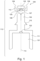
- FIG. 1 a cross-sectional schematic view of an acoustical assembly 100 comprising a receiver unit 101, a nozzle 113 comprising three portions 105, 111, 112 and a microphone unit 102 is depicted.
- the receiver unit 101 comprises a sound outlet opening 103 through which opening 103 sound pressure waves escape the receiver unit 101.
- the receiver unit 101 is adapted to generate sound within the audible range in response to a provided drive signal.
- the microphone unit 102 comprises a sound inlet opening 104 through which opening 104 incoming sound pressure waves enter the microphone unit 102.
- the microphone unit 102 provides an electrical output signal in response to detected sound pressure waves.
- the receiver unit 101 and the microphone unit 102 are arranged in line with each other, i.e. along the imaginary longitudinal centre line 114.
- the nozzle (or spout) 113 comprises three portions - a first portion 111 comprising a receiver unit mount for housing at least part of the receiver unit 101, a second portion 112 comprising a microphone unit mount for housing at least part of the microphone unit 102 and a third portion 105 connecting the first and second nozzle portions 111, 112.
- the third nozzle portion 105 comprises at least one sound channel adapted to guide generated sound pressure waves from the sound outlet opening 103 of the receiver unit 101 to at least one sound outlet opening 106, 107 of the nozzle 113 as indicated by the arrows. Possible implementations of the at least one sound channel within the third nozzle portion 105 will be discussed in further details in relation to Figs. 4 and 5 .
- the three nozzle portions 105, 111, 112 are preferably manufactured as a one-piece structure, such as a moulded one-piece structure.
- the second nozzle portion 112 comprises a microphone unit mount in the form of an indentation into which a least part of the microphone unit 102 is arranged.
- the sound inlet opening 104 of the microphone unit 102 faces, or is oriented towards, the interior of the nozzle 113 in order to prevent that ear wax, moisture or other undesired objects block or damage the microphone unit 102.
- Incoming sound pressure waves thus enter the sound channels 108, 109 (free space regions) between the microphone unit 102 and the indentation before reaching the sound inlet opening 104 as indicated by the two arrows.
- Electrical signals to and from the microphone unit 102 are provided via electrical wires through the third nozzle portion 105.
- Retaining members 110 may optionally be arranged on an exterior surface of the third nozzle portion 105. Such retaining members 110 may be used for securing a positioning member (not shown), such as a dome, to the third nozzle portion 105.
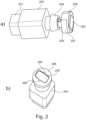
- Figs. 2a and 2b two three-dimensional views of an acoustical assembly according to the present invention are depicted.
- the receiver unit 201 is inserted into the first portion 203 of the nozzle, whereas the second portion 207 of the nozzle houses the microphone unit 202.
- A, preferably replaceable, wax protection member 206 is secured to the second portion 207 of the nozzle.
- the wax protection member 206 is adapted to secure the microphone unit 202 to the second portion 207 of the nozzle, and protect the microphone unit 202 against ear wax.
- the wax protection member 206 comprises sound inlet openings 208, 209 which are aligned with respective sound channels (not shown) of the second portion 207 of the nozzle in order to guide incoming sound pressure waves to a sound inlet opening (not shown) of the microphone unit 202.
- the nozzle further comprises a retaining member 204 and oppositely arranged sound outlet openings 205 (only one opening is visible) for the receiver unit 201.
- the oppositely arranged sound outlet openings 205 are acoustically connected to the sound outlet opening (not shown) of the receiver unit 201 via at least one sound channel within the nozzle.
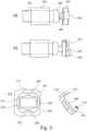
- FIG. 3b two side views of the acoustical assembly of Figs. 2a and 2b are depicted.
- the acoustical assembly is rotated 90 degrees around a longitudinal axis compared to Fig. 3a .
- the receiver unit 301 is inserted into the first portion 303 of the nozzle, said nozzle further comprising a retaining member 304, oppositely arranged sound outlet openings 305 (only one opening is visible in Fig. 3a ) and a second portion 307 for housing the microphone unit 302.
- a preferably replaceable wax protection member 306 is secured to the second portion 307 of the nozzle.
- FIG. 3c shows a top view of the acoustical assembly without the wax protection member 306.
- the microphone unit 302 is arranged at least partly in an indentation 316 provided in the second portion 307 of the nozzle.
- a small gap 317 of free space is provided between the microphone unit 302 and the edges of the indentation 316.
- sound channels 308, 309 are provided on both sides of the microphone unit 302 in order to guide incoming sound pressure waves to a sound inlet opening (not shown) of the microphone unit 302.
- the sound channels 308, 309 are aligned with sound inlet openings 208, 209 of the wax protection member 206, cf. Fig. 2b .
- a pair of oppositely arranged tracks 310, 311 are provided in the second portion 307 of the nozzle. These tracks 310, 311 are adapted to receive respective resilient leg portions 312, 313 of the wax protection member 306. Respective locking arrangements 314, 315 are provided at the ends of the legs portions 312, 313. These locking arrangements 314, 315 are adapted to engage with corresponding locking arrangements (not shown) provided at the ends of the tracks 310, 311 whereby the wax protection member 306 clicks onto the second portion 307 of the nozzle.
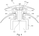
- Fig. 4 depicts a cross-sectional schematic view of an exemplary embodiment 400 of the acoustical assembly of the present invention.
- this embodiment comprises an in line arrangement of a receiver unit 401, a nozzle 403, 404 having two oppositely arranged sound outlet openings 405, 406 and a microphone unit 402. Sound pressure waves escaping the sound outlet opening 412 of the receiver unit 401 are guided to the two oppositely arranged sound outlet openings 405, 406 via respective sound channels 407, 408 within the nozzle as indicated by the two arrows.
- the microphone unit 402 is at least partly arranged in an indentation 414 in the nozzle portion 404 with its sound inlet opening 413 facing the interior of the nozzle in order to prevent that ear wax, moisture or other undesired objects block the sound inlet opening 413 of the microphone unit 402 or damages the microphone unit 402.
- incoming sound pressure waves are allowed to reach the sound inlet opening 413 of the microphone unit 402 via a gap between the microphone unit 402 and the indentation 414.
- the embodiment depicted in Fig. 4 further comprises a preferably soft and/or flexible dome-shaped positioning member 410 for positioning the acoustical assembly correctly in the ear canal.
- the positioning member 410 is preferably manufactured of a soft and flexible material, such as silicone, in order to increase comfort for the user while wearing the acoustical assembly. Moreover, a deflection member 411 comprising a sound inlet opening 409 for the microphone unit 402 is provided. As depicted in Fig. 4 the sound inlet opening 409 for the microphone unit 402 is arranged on top of the deflection member 411 thus facing the ear drum when inserted in an ear canal.
- the deflection member 411 and the positioning member 410 preferably form an integral one-piece moulded structure with sound outlet openings aligned with the corresponding sound outlet openings 405, 406 of the nozzle.
- Fig. 5 depicts a cross-sectional schematic view of another exemplary embodiment 500 of the acoustical assembly of the present invention. Similar to the embodiment of Fig. 4 this embodiment also comprises an in line arrangement of a receiver unit 501, a nozzle 503, 504 and a microphone unit 502. In contrast to the embodiment of Fig. 4 the embodiment of Fig. 5 comprises only a single sound outlet opening 505. Again, sound pressure waves escaping the sound outlet opening 510 of the receiver unit 501 are guided to the sound outlet opening 505 via a sound channel 506 within the nozzle as indicated by the arrow.
- the microphone unit 502 is at least partly arranged in an indentation 512 in the nozzle portion 504 with its sound inlet opening 511 facing the interior of the nozzle in order to prevent that ear wax, moisture or other undesired objects block the sound inlet opening 511 of the microphone unit 502 or damages the microphone unit 502.
- incoming sound pressure waves are allowed to reach the sound inlet opening 511 of the microphone unit 502 via a passage in or beneath the deflection member 509 and a gap between the microphone unit 502 and the indentation 512. Similar to the embodiment shown in Fig. 4 the embodiment depicted in Fig.
- the 5 also comprises a preferably soft and flexible dome-shaped positioning member 508 for positioning the acoustical assembly correctly in the ear canal.
- the positioning member 508 is preferably manufactured of a flexible material, such as silicone, thus increasing the comfort for the user during use.
- a deflection member 509 is also provided. As depicted in Fig. 5 a sound inlet opening 507 for the microphone unit 502 is provided in or beneath the deflection member 509 as indicated by the arrow.
- the deflection member 509 and the positioning member 508 preferably form an integral one-piece moulded structure with a sound outlet opening aligned with the opening 505 of the nozzle.
- the acoustical assembly of the present invention preferably forms part of a hearing device, i.e. hearing aids/hearables earbuds and the like, to be inserted into the ear canal of the user.
- the overall dimensions and shape of the acoustical assembly are thus limited in order to comply with such space limited applications.
Landscapes
- Engineering & Computer Science (AREA)
- Physics & Mathematics (AREA)
- Acoustics & Sound (AREA)
- Signal Processing (AREA)
- Health & Medical Sciences (AREA)
- Otolaryngology (AREA)
- Manufacturing & Machinery (AREA)
- General Health & Medical Sciences (AREA)
- Neurosurgery (AREA)
- Soundproofing, Sound Blocking, And Sound Damping (AREA)
- Headphones And Earphones (AREA)
Description
- The present invention relates to an acoustical assembly adapted to be inserted into an ear canal, said acoustical assembly comprising a receiver unit adapted to generate sound pressure waves, a microphone unit adapted to detect sound pressure waves inside the ear canal when the acoustical assembly is inserted in the ear canal, and a nozzle comprising a receiver unit mount adapted to house at least part of the receiver unit, wherein the nozzle comprises at least one sound channel adapted to guide generated sound pressure waves from a receiver unit outlet opening to at least one sound outlet opening of the nozzle. In particular, the present invention relates to an acoustical assembly comprising a receiver unit and a microphone unit secured to a nozzle in an in line arrangement.
- Various combinations of receivers and microphones have been used in relation to hearing devices, i.e. hearing aids/hearables, earbuds and the like. The role of the microphone is to detect the sound pressure level generated by the receiver in the ear canal. By detecting the sound pressure level with the microphone the sound pressure level generated by the receiver in the ear canal can be monitored and limited.
- Typical combinations of receivers and microphones are for example discussed in prior art references
US 2008/0107287 A1 ,US 2017/0048608 A1 , andUS 2008/0181440 A1 . These references both discuss in line implementations of receiver/microphone arrangements where the microphones are arranged in line with the respective receivers. When inserted into the ear canal the microphones are positioned closer to the ear drum than the respective receivers. - The in line arrangements suggested in both
US 2008/0107287 A1 andUS 2008/0181440 A1 appear disadvantageous in that the positioning, and in particular the orientation, of the microphones (with their sound inlets facing the ear drum) makes them vulnerable to, for example, ear wax, moisture or other undesired objects being present in the ear canal. In particular, moisture from the ear canal may potentially enter the microphone and thus damage it due to electrical short circuiting, whereas ear wax may potentially block the sound inlet opening of the microphone. - It may thus be seen as an object of embodiments of the present invention to provide a receiver/microphone arrangement where the microphone is less vulnerable and thus protected against for example ear wax and moisture while still being positioned close to the ear drum in the ear canal.
- It may be seen as a further object of embodiments of the present invention to provide a receiver/microphone arrangement with an improved fit rate.
- The above-mentioned object is complied with by providing, in a first aspect, an acoustical assembly according to claim 1. It is adapted to be inserted into an ear canal, said acoustical assembly comprising
- a receiver unit adapted to generate sound pressure waves,
- a microphone unit adapted to detect sound pressure waves inside the ear canal when the acoustical assembly is inserted in the ear canal, and
- a nozzle comprising a receiver unit mount adapted to house at least part of the receiver unit, wherein the nozzle comprises at least one sound channel adapted to guide generated sound pressure waves from a receiver unit outlet opening to at least one sound outlet opening of the nozzle
- The acoustical assembly of the present invention is advantageous in that the mutual positioning of the at least one sound outlet opening, the receiver unit mount and the microphone unit mount form, in combination, an elongated structure which improves the fit rate of the overall acoustical assembly.
- Preferably, the microphone unit is arranged in the microphone unit mount in such a way that a sound inlet opening of the microphone unit is oriented towards an interior portion of the microphone unit mount of the nozzle. This is advantageous in that the orientation of the microphone unit prevents that ear wax, moisture or other undesired objects block the sound inlet opening of the microphone unit or damage the microphone unit.
- The acoustical assembly of the present invention is further advantageous due to its simple design where a receiver unit and a microphone unit are attached to the same nozzle in an in line arrangement. Preferably, the at least one sound outlet opening of the nozzle is arranged between the receiver unit mount and the microphone unit mount. The simple design also facilitates that different receiver units and different microphone units may be combined. Further, the sound inlet of the microphone unit and the sound outlet of the receiver unit are spatially separated which makes it less susceptible to acoustic leaks.
- In the present context a receiver unit is to be understood as a unit being capable of generating sound pressure waves, such as audio sound, in response to an electrical drive signal applied thereto. The receiver unit may be a moving armature type receiver unit. A microphone unit is to be understood as a unit being capable of detecting sound pressure waves, such as audio sound, and generate an electrical signal in response thereto. The microphone unit may be a MEMS microphone unit, an electret microphone, or a microphone comprising a biased membrane.
- As addressed above, the microphone unit is arranged in the microphone unit mount in such a way that its sound inlet opening is oriented towards, i.e. facing, an interior portion of the microphone unit mount of the nozzle. Thus, the sound inlet opening of the microphone unit is not oriented towards the ear drum or the ear canal. Instead the sound inlet opening of the microphone unit faces the nozzle which is advantageous in that this orientation prevents, as mentioned above, that ear wax, moisture or other undesired objects blocking the sound inlet opening of the microphone unit or damage the microphone unit.
- Preferably, the nozzle defines a longitudinal centre axis, and the receiver unit and the microphone unit preferably are arranged along said longitudinal centre axis. In this manner the overall shape of the acoustical assembly may become a longitudinal structure that fits easily into a typical ear canal. Preferably, the receiver unit and the microphone unit are arranged symmetrically around, and in line with, said longitudinal centre axis.
- As already mentioned, the microphone unit is arranged in the microphone unit mount in such a way that its sound inlet opening is oriented towards, (or facing), an interior portion of the microphone unit mount of the nozzle. In order to facilitate this advantageous orientation of the microphone unit, the microphone unit mount of the nozzle preferably comprises an indentation into which indentation the microphone unit is at least partly arranged. The microphone unit may thus be arranged in the indentation with its sound inlet opening facing the bottom surface of the indentation. As already addressed the role of the microphone unit is to detect the sound pressure level generated by the receiver in the ear canal. In order to fulfil this role the microphone unit mount preferably comprises at least one sound channel adapted to guide sound pressure waves from the ear canal to the sound inlet opening of the microphone unit, although the sound inlet opening is oriented away from the ear canal.
- The acoustical assembly preferably comprises a wax protection member adapted to be attached to the microphone unit mount of the nozzle. Preferably this wax protection member is replaceable. The wax protection member preferably is attached to the microphone unit mount via a user friendly click-on locking mechanism. This click-on locking mechanism is advantageous in that it allows the wax protection member as well as the microphone unit be easily attached to, or easily detached from, the microphone unit mount. The wax protection member is adapted to prevent that ear wax from the ear canal reaches the sound inlet opening of the microphone unit.
- Thus, the role of wax protection member is to prevent that ear wax blocks the sound inlet opening of the microphone unit which may increase the life span of the microphone unit. Moreover, the wax protection member is adapted to maintain the microphone unit in a fixed position relative to the microphone unit mount of the nozzle. The wax protection member preferably comprises at least one sound inlet opening adapted to be aligned with the at least one sound channel of the microphone unit mount. The dimensions of the at least one sound inlet opening of the wax protection member may be smaller than the corresponding dimensions of the at least one sound channel of the microphone unit mount. The at least one sound inlet opening of the wax protection member may then act as a spatial filter or mesh for ear wax or other undesired objects.
- The at least one sound outlet opening of the nozzle preferably is arranged between the receiver unit mount and the microphone unit mount. In particular, the at least one sound outlet opening of the nozzle may be arranged between the receiver unit mount and the microphone unit mount though closest to the microphone unit mount.
- The number of sound outlet openings in the nozzle may be chosen to meet specific demands. Thus, preferably, a single sound outlet opening of the nozzle is arranged between the receiver unit mount and the microphone unit mount. Alternatively, a pair of oppositely arranged sound outlet openings may be arranged between the receiver unit mount and the microphone unit mount.
- Preferably, the acoustical assembly further comprises a dome-shaped positioning member adapted to ensure correct positioning of the acoustical assembly in the ear canal. Preferably this dome-shaped positioning member is replaceable. Preferably this dome-shaped positioning member is flexible. The dome-shaped positioning member may be attached to the nozzle at a position between the receiver unit mount and the microphone unit mount. By dome-shaped is meant that the positioning member may take the shape of a part of a dome. The flexibility of the dome-shaped positioning member is advantageous in that the positioning member may then, due to its flexibility, adapt to the shape and contours of almost any ear canal and thus minimise undesired acoustical leakage. Moreover, the dome-shaped positioning member is symmetrical around the longitudinal centre axis so the acoustical performance of the acoustical assembly is insensitive to rotations of the acoustical assembly around the longitudinal centre axis. The acoustical assembly may further comprise a deflection member at least partly surrounding the microphone unit mount. The deflection member is preferably replaceable. Preferably this deflection member is flexible. The dome-shaped positioning member and the deflection member preferably form a one-piece structure of the same, preferably flexible material, such as silicone.
- The one-piece structure may comprise at least one sound outlet opening aligned with the at least one sound outlet opening of the nozzle, and at least one sound inlet opening for the microphone unit. The at least one sound inlet opening for the microphone unit is preferably arranged through the deflection member. Alternatively, the at least one sound inlet opening for the microphone unit may be arranged between the positioning member and the deflection member, such as immediately beneath the deflection member.
- In a second aspect the present invention relates to a hearing device comprising an acoustical assembly according to the first aspect.
- The present invention will now be described in further details with reference to the accompanying figures where
-
Fig. 1 shows a cross-sectional schematic view of an acoustical assembly comprising a receiver unit, a nozzle and a microphone unit arranged in line, -
Fig. 2 shows three-dimensional views of an acoustical assembly comprising an in line arrangement of a receiver unit, a nozzle and a microphone unit, -
Fig. 3 shows side and top views of an acoustical assembly comprising an in line arrangement of a receiver unit, a nozzle and a microphone unit arranged in line, -
Fig. 4 shows a cross-sectional schematic view of an embodiment of the acoustical assembly comprising a receiver unit, a nozzle having two oppositely arranged sound outlet openings, a microphone unit, a positioning member and a deflection member with a top sound inlet opening for the microphone unit, and -
Fig. 5 shows a cross-sectional schematic view of another embodiment of the acoustical assembly comprising a receiver unit, a nozzle having a single sound outlet, a microphone unit, a positioning member and a deflection member with a side sound inlet opening for the microphone unit. - As already discussed, the present invention relates to an acoustical assembly comprising a receiver unit and a nozzle (or spout) secured thereto. Moreover, a microphone unit is secured to the nozzle in such a way that its sound inlet opening is oriented towards, i.e. facing, the interior of the nozzle in order to prevent that ear wax, moisture or other undesired objects block the sound inlet opening of the microphone unit or damage the microphone unit.
- Referring now to
Fig. 1 , a cross-sectional schematic view of anacoustical assembly 100 comprising areceiver unit 101, anozzle 113 comprising threeportions microphone unit 102 is depicted. Thereceiver unit 101 comprises asound outlet opening 103 through which opening 103 sound pressure waves escape thereceiver unit 101. Thereceiver unit 101 is adapted to generate sound within the audible range in response to a provided drive signal. Similarly, themicrophone unit 102 comprises a sound inlet opening 104 through which opening 104 incoming sound pressure waves enter themicrophone unit 102. Themicrophone unit 102 provides an electrical output signal in response to detected sound pressure waves. Thereceiver unit 101 and themicrophone unit 102 are arranged in line with each other, i.e. along the imaginarylongitudinal centre line 114. - The nozzle (or spout) 113 comprises three portions - a
first portion 111 comprising a receiver unit mount for housing at least part of thereceiver unit 101, asecond portion 112 comprising a microphone unit mount for housing at least part of themicrophone unit 102 and athird portion 105 connecting the first andsecond nozzle portions third nozzle portion 105 comprises at least one sound channel adapted to guide generated sound pressure waves from the sound outlet opening 103 of thereceiver unit 101 to at least onesound outlet opening nozzle 113 as indicated by the arrows. Possible implementations of the at least one sound channel within thethird nozzle portion 105 will be discussed in further details in relation toFigs. 4 and5 . - The three
nozzle portions - The
second nozzle portion 112 comprises a microphone unit mount in the form of an indentation into which a least part of themicrophone unit 102 is arranged. As depicted inFig. 1 the sound inlet opening 104 of themicrophone unit 102 faces, or is oriented towards, the interior of thenozzle 113 in order to prevent that ear wax, moisture or other undesired objects block or damage themicrophone unit 102. Incoming sound pressure waves thus enter thesound channels 108, 109 (free space regions) between themicrophone unit 102 and the indentation before reaching the sound inlet opening 104 as indicated by the two arrows. Electrical signals to and from themicrophone unit 102 are provided via electrical wires through thethird nozzle portion 105. - Retaining
members 110 may optionally be arranged on an exterior surface of thethird nozzle portion 105. Such retainingmembers 110 may be used for securing a positioning member (not shown), such as a dome, to thethird nozzle portion 105. - Turning now to
Figs. 2a and 2b , two three-dimensional views of an acoustical assembly according to the present invention are depicted. As seen inFig. 2a , thereceiver unit 201 is inserted into thefirst portion 203 of the nozzle, whereas thesecond portion 207 of the nozzle houses themicrophone unit 202. A, preferably replaceable,wax protection member 206 is secured to thesecond portion 207 of the nozzle. Thewax protection member 206 is adapted to secure themicrophone unit 202 to thesecond portion 207 of the nozzle, and protect themicrophone unit 202 against ear wax. - As seen from the top view of
Fig. 2b thewax protection member 206 comprisessound inlet openings second portion 207 of the nozzle in order to guide incoming sound pressure waves to a sound inlet opening (not shown) of themicrophone unit 202. Returning now toFig. 2a the nozzle further comprises a retainingmember 204 and oppositely arranged sound outlet openings 205 (only one opening is visible) for thereceiver unit 201. The oppositely arrangedsound outlet openings 205 are acoustically connected to the sound outlet opening (not shown) of thereceiver unit 201 via at least one sound channel within the nozzle. - Referring now to
Figs. 3a and 3b two side views of the acoustical assembly ofFigs. 2a and 2b are depicted. InFig. 3b the acoustical assembly is rotated 90 degrees around a longitudinal axis compared toFig. 3a . Again, thereceiver unit 301 is inserted into thefirst portion 303 of the nozzle, said nozzle further comprising a retainingmember 304, oppositely arranged sound outlet openings 305 (only one opening is visible inFig. 3a ) and asecond portion 307 for housing themicrophone unit 302. Similar toFig. 2 , a preferably replaceablewax protection member 306 is secured to thesecond portion 307 of the nozzle.Fig. 3c shows a top view of the acoustical assembly without thewax protection member 306. As seen inFig. 3c themicrophone unit 302 is arranged at least partly in anindentation 316 provided in thesecond portion 307 of the nozzle. Asmall gap 317 of free space is provided between themicrophone unit 302 and the edges of theindentation 316. Moreover,sound channels microphone unit 302 in order to guide incoming sound pressure waves to a sound inlet opening (not shown) of themicrophone unit 302. Thesound channels sound inlet openings wax protection member 206, cf.Fig. 2b . A pair of oppositely arrangedtracks second portion 307 of the nozzle. Thesetracks resilient leg portions wax protection member 306.Respective locking arrangements legs portions arrangements tracks wax protection member 306 clicks onto thesecond portion 307 of the nozzle. -
Fig. 4 depicts a cross-sectional schematic view of anexemplary embodiment 400 of the acoustical assembly of the present invention. As depicted inFig. 4 this embodiment comprises an in line arrangement of areceiver unit 401, anozzle sound outlet openings microphone unit 402. Sound pressure waves escaping the sound outlet opening 412 of thereceiver unit 401 are guided to the two oppositely arrangedsound outlet openings respective sound channels microphone unit 402 is at least partly arranged in anindentation 414 in thenozzle portion 404 with its sound inlet opening 413 facing the interior of the nozzle in order to prevent that ear wax, moisture or other undesired objects block the sound inlet opening 413 of themicrophone unit 402 or damages themicrophone unit 402. As indicated by the two arrows around themicrophone unit 402 incoming sound pressure waves are allowed to reach the sound inlet opening 413 of themicrophone unit 402 via a gap between themicrophone unit 402 and theindentation 414. The embodiment depicted inFig. 4 further comprises a preferably soft and/or flexible dome-shapedpositioning member 410 for positioning the acoustical assembly correctly in the ear canal. The positioningmember 410 is preferably manufactured of a soft and flexible material, such as silicone, in order to increase comfort for the user while wearing the acoustical assembly. Moreover, adeflection member 411 comprising a sound inlet opening 409 for themicrophone unit 402 is provided. As depicted inFig. 4 the sound inlet opening 409 for themicrophone unit 402 is arranged on top of thedeflection member 411 thus facing the ear drum when inserted in an ear canal. Thedeflection member 411 and thepositioning member 410 preferably form an integral one-piece moulded structure with sound outlet openings aligned with the correspondingsound outlet openings -
Fig. 5 depicts a cross-sectional schematic view of anotherexemplary embodiment 500 of the acoustical assembly of the present invention. Similar to the embodiment ofFig. 4 this embodiment also comprises an in line arrangement of areceiver unit 501, anozzle microphone unit 502. In contrast to the embodiment ofFig. 4 the embodiment ofFig. 5 comprises only a singlesound outlet opening 505. Again, sound pressure waves escaping the sound outlet opening 510 of thereceiver unit 501 are guided to thesound outlet opening 505 via asound channel 506 within the nozzle as indicated by the arrow. Themicrophone unit 502 is at least partly arranged in anindentation 512 in thenozzle portion 504 with its sound inlet opening 511 facing the interior of the nozzle in order to prevent that ear wax, moisture or other undesired objects block the sound inlet opening 511 of themicrophone unit 502 or damages themicrophone unit 502. As indicated by the arrow to the right of themicrophone unit 502 incoming sound pressure waves are allowed to reach the sound inlet opening 511 of themicrophone unit 502 via a passage in or beneath thedeflection member 509 and a gap between themicrophone unit 502 and theindentation 512. Similar to the embodiment shown inFig. 4 the embodiment depicted inFig. 5 also comprises a preferably soft and flexible dome-shapedpositioning member 508 for positioning the acoustical assembly correctly in the ear canal. The positioningmember 508 is preferably manufactured of a flexible material, such as silicone, thus increasing the comfort for the user during use. Adeflection member 509 is also provided. As depicted inFig. 5 a sound inlet opening 507 for themicrophone unit 502 is provided in or beneath thedeflection member 509 as indicated by the arrow. Thedeflection member 509 and thepositioning member 508 preferably form an integral one-piece moulded structure with a sound outlet opening aligned with theopening 505 of the nozzle. - The acoustical assembly of the present invention preferably forms part of a hearing device, i.e. hearing aids/hearables earbuds and the like, to be inserted into the ear canal of the user. The overall dimensions and shape of the acoustical assembly are thus limited in order to comply with such space limited applications.
- Although the invention has been discussed in the foregoing with reference to exemplary embodiments of the invention, the invention is not restricted to these particular embodiments which can be varied in many ways without departing from the invention. The discussed exemplary embodiments shall therefore not be used to construe the appended claims strictly in accordance therewith. On the contrary, the embodiments are merely intended to explain the wording of the appended claims, without intent to limit the claims to these exemplary embodiments. The scope of protection of the invention shall therefore be construed in accordance with the appended claims only.
Claims (15)
- An acoustical assembly (100) adapted to be inserted into an ear canal, said acoustical assembly (100) comprising- a receiver unit (101) adapted to generate sound pressure waves,- a microphone unit (102) adapted to detect sound pressure waves inside the ear canal when the acoustical assembly (100) is inserted in the ear canal, and- a nozzle (113) comprising a receiver unit mount (111) adapted to house at least part of the receiver unit (101), wherein the nozzle (113) comprises at least one sound channel adapted to guide generated sound pressure waves from a receiver unit outlet opening (103) to at least one sound outlet opening (106, 107) of the nozzle (113),wherein
the nozzle (113) further comprises a microphone unit mount (112) adapted to house at least part of the microphone unit (102), characterised in that the microphone unit (102) is arranged in the microphone unit mount (112) in such a way that a sound inlet opening (104) of the microphone unit (102) is not oriented towards the ear drum when the acoustical assembly is inserted in the ear canal. - An acoustical assembly according to claim 1, characterised in that the microphone unit (102) is arranged in the microphone unit mount (112) in such a way that a sound inlet opening (104) of the microphone unit (102) is oriented towards an interior portion of the microphone unit mount (112) of the nozzle (113).
- An acoustical assembly according to claims 1 or 2, characterised in that the nozzle (113) defines a longitudinal centre axis (114), and the receiver unit (101) and the microphone unit (102) are arranged symmetrically around, and in line with, said longitudinal centre axis (114).
- An acoustical assembly according to any of the preceding claims, characterised in that the microphone unit mount (112) of the nozzle (113) comprises an indentation into which indentation the microphone unit (102) is at least partly arranged.
- An acoustical assembly according to any of the preceding claims, characterised in that the microphone unit mount (112) comprises at least one sound channel (108, 109) adapted to guide sound pressure waves from the ear canal to the sound inlet opening (104) of the microphone unit (102).
- An acoustical assembly according to any of the preceding claims characterised in that the assembly further comprises a wax protection member (306) adapted to be attached to the microphone unit mount (307) of the nozzle, the wax protection member (306) further adapted to prevent that ear wax from the ear canal reaches the sound inlet opening of the microphone unit (302).
- An acoustical assembly according to claim 6, characterised in that the wax protection member (306) comprises at least one sound inlet opening (208, 209) adapted to be aligned with the at least one sound channel of the microphone unit mount (308, 309).
- An acoustical assembly according to any of the preceding claims, characterised in that the at least one sound outlet opening of the nozzle (106, 107) is arranged between the receiver unit mount (111) and the microphone unit mount (112).
- An acoustical assembly according to claim 8, characterised in that a single sound outlet opening (505) of the nozzle is arranged between the receiver unit mount and the microphone unit mount, or in that a pair of oppositely arranged sound outlet openings (106, 107, 405, 406) of the nozzle are arranged between the receiver unit mount and the microphone unit mount.
- An acoustical assembly according to any of the preceding claims, characterised in that the assembly further comprises a dome-shaped positioning member (410, 508) adapted to ensure correct positioning of the acoustical assembly in the ear canal, wherein the dome-shaped positioning member (410, 508) is attached to the nozzle between the receiver unit mount (403, 503) and the microphone unit mount (404, 504).
- An acoustical assembly according to claim 10, characterised in that the assembly further comprises a deflection member (411, 509) at least partly surrounding the microphone unit mount (404, 504).
- An acoustical assembly according to claim 11, characterised in that the dome-shaped positioning member (410, 508) and the deflection member (411, 509) form a one-piece structure of the same material.
- An acoustical assembly according to claim 12, characterised in that the one-piece structure comprises at least one sound outlet opening aligned with the at least one sound outlet opening (405, 406, 505) of the nozzle, and that the one-piece structure comprises at least one sound inlet opening (409, 507) for the microphone unit (102).
- An acoustical assembly according to claim 13, characterised in that the at least one sound inlet opening (409) for the microphone unit (402) is arranged through the deflection member (411), or that the at least one sound inlet opening (507) for the microphone unit (502) is arranged between the positioning member (508) and the deflection member (509).
- A hearing device comprising an acoustical assembly according to any of the preceding claims.
Applications Claiming Priority (2)
| Application Number | Priority Date | Filing Date | Title |
|---|---|---|---|
| DKPA202070553 | 2020-08-26 | ||
| PCT/EP2021/070285 WO2022042951A1 (en) | 2020-08-26 | 2021-07-20 | Microphone unit arranged on top of receiver unit nozzle |
Publications (2)
| Publication Number | Publication Date |
|---|---|
| EP4205407A1 EP4205407A1 (en) | 2023-07-05 |
| EP4205407B1 true EP4205407B1 (en) | 2024-09-11 |
Family
ID=80354653
Family Applications (1)
| Application Number | Title | Priority Date | Filing Date |
|---|---|---|---|
| EP21748557.2A Active EP4205407B1 (en) | 2020-08-26 | 2021-07-20 | Microphone unit arranged on top of receiver unit nozzle |
Country Status (5)
| Country | Link |
|---|---|
| US (2) | US12470861B2 (en) |
| EP (1) | EP4205407B1 (en) |
| CN (1) | CN115943642B (en) |
| DK (1) | DK4205407T3 (en) |
| WO (1) | WO2022042951A1 (en) |
Families Citing this family (3)
| Publication number | Priority date | Publication date | Assignee | Title |
|---|---|---|---|---|
| KR102871761B1 (en) * | 2021-01-12 | 2025-10-16 | 삼성전자 주식회사 | Microphone module and electronic device including the same |
| WO2025202075A1 (en) | 2024-03-25 | 2025-10-02 | Sonion Nederland B.V. | A receiver-in-canal assembly |
| WO2025252820A1 (en) | 2024-06-07 | 2025-12-11 | Sonion Nederland B.V. | Custom-made in-ear audio assembly |
Citations (15)
| Publication number | Priority date | Publication date | Assignee | Title |
|---|---|---|---|---|
| US4291203A (en) | 1979-09-11 | 1981-09-22 | Gaspare Bellafiore | Hearing aid device |
| CH684231A5 (en) | 1992-08-20 | 1994-07-29 | Marco Parodi | Hearing aid to be worn in the auditory canal of a person |
| WO2000042817A1 (en) | 1999-01-15 | 2000-07-20 | Sonic Innovations | Hearing aid with conformal tip, integrated vent and retrieval tube |
| CN2435886Y (en) * | 2000-07-17 | 2001-06-20 | 许宝霞 | Eardrum vibration type hands-free receiver for mobile phone |
| WO2005076991A2 (en) | 2004-02-05 | 2005-08-25 | Insound Medical, Inc. | Extended wear canal device with common microphone-battery air cavity |
| US20080181440A1 (en) | 2007-01-29 | 2008-07-31 | Siemens Hearing Instruments Inc. | Combined Receiver and Ear-Canal Microphone Assembly for a Hearing Instrument |
| EP2134107B1 (en) | 2008-06-11 | 2013-09-25 | Sonion Nederland B.V. | Method of operating a hearing instrument with improved venting |
| EP2795923B1 (en) | 2011-12-23 | 2015-11-04 | Sonova AG | Tip-plate assembly, hearing device with a tip-plate assembly and method of manufacturing a hearing device with a tip-plate assembly |
| US20160324478A1 (en) | 2015-05-08 | 2016-11-10 | Steven Wayne Goldstein | Biometric, physiological or environmental monitoring using a closed chamber |
| US20170048608A1 (en) | 2015-08-10 | 2017-02-16 | Cotron Corporation | In-ear headset module |
| EP3313097A1 (en) | 2016-10-19 | 2018-04-25 | Sonion Nederland B.V. | An ear bud or dome |
| WO2019052714A1 (en) | 2017-09-18 | 2019-03-21 | Sonova Ag | Communication device comprising an acoustical seal and a vent opening |
| US20190208301A1 (en) | 2017-12-29 | 2019-07-04 | Knowles Electronics, Llc | Audio device with acoustic valve |
| US20200077211A1 (en) | 2017-02-27 | 2020-03-05 | Oticon A/S | Hearing device with a microphone structure |
| EP3422734B1 (en) | 2017-06-29 | 2020-05-20 | Starkey Laboratories, Inc. | Flanged earbud and hearing device including same |
Family Cites Families (18)
| Publication number | Priority date | Publication date | Assignee | Title |
|---|---|---|---|---|
| DE102005019148B3 (en) | 2005-04-25 | 2006-08-17 | Siemens Audiologische Technik Gmbh | In-the-ear hearing aid with ear-duct microphone, includes earwax protection system arranged with microphone |
| CN2829265Y (en) | 2005-08-22 | 2006-10-18 | 蔡锦绸 | Headphones that reduce distractions |
| US20070160243A1 (en) * | 2005-12-23 | 2007-07-12 | Phonak Ag | System and method for separation of a user's voice from ambient sound |
| US8027481B2 (en) | 2006-11-06 | 2011-09-27 | Terry Beard | Personal hearing control system and method |
| US8224005B2 (en) | 2007-08-24 | 2012-07-17 | Surefire, Llc | Hearing aid extension |
| US8649540B2 (en) * | 2009-10-30 | 2014-02-11 | Etymotic Research, Inc. | Electronic earplug |
| WO2013075255A1 (en) * | 2011-11-22 | 2013-05-30 | Phonak Ag | A method of processing a signal in a hearing instrument, and hearing instrument |
| WO2014177214A1 (en) * | 2013-05-02 | 2014-11-06 | Phonak Ag | Hearing instrument comprising an ear canal microphone with active control loop |
| EP2819435A1 (en) * | 2013-06-26 | 2014-12-31 | Oticon A/s | Vented dome |
| DK2843971T3 (en) * | 2013-09-02 | 2019-02-04 | Oticon As | Hearing aid device with microphone in the ear canal |
| JP2016116153A (en) | 2014-12-17 | 2016-06-23 | スター精密株式会社 | Ear canal-mounted earphone microphone |
| US9635452B2 (en) | 2015-08-05 | 2017-04-25 | Bose Corporation | Noise reduction with in-ear headphone |
| DK3148218T3 (en) * | 2015-09-18 | 2020-02-24 | Sonion Nederland Bv | ACOUSTIC MODULE WITH ACOUSTIC FILTER |
| EP3624466B1 (en) * | 2015-09-30 | 2024-04-03 | Oticon A/s | Hearing aid comprising a receiver assembly |
| TW201813416A (en) | 2016-09-30 | 2018-04-01 | 美律實業股份有限公司 | Noise-cancelling earphone |
| DK3324644T3 (en) * | 2016-11-17 | 2021-01-04 | Oticon As | WIRELESS HEARING DEVICE WITH STABILIZING GUIDANCE BETWEEN TRAGUS AND ANTITRAGUS |
| US11234085B2 (en) * | 2019-11-21 | 2022-01-25 | Bose Corporation | Earpieces and related articles and devices |
| CN210609653U (en) | 2020-01-08 | 2020-05-22 | 东莞市逸音电子科技有限公司 | Noise reduction earphone with microphone arranged in front cavity sound mouth |
-
2021
- 2021-07-20 EP EP21748557.2A patent/EP4205407B1/en active Active
- 2021-07-20 DK DK21748557.2T patent/DK4205407T3/en active
- 2021-07-20 CN CN202180052426.XA patent/CN115943642B/en active Active
- 2021-07-20 US US18/042,271 patent/US12470861B2/en active Active
- 2021-07-20 WO PCT/EP2021/070285 patent/WO2022042951A1/en not_active Ceased
-
2025
- 2025-10-22 US US19/365,806 patent/US20260046547A1/en active Pending
Patent Citations (15)
| Publication number | Priority date | Publication date | Assignee | Title |
|---|---|---|---|---|
| US4291203A (en) | 1979-09-11 | 1981-09-22 | Gaspare Bellafiore | Hearing aid device |
| CH684231A5 (en) | 1992-08-20 | 1994-07-29 | Marco Parodi | Hearing aid to be worn in the auditory canal of a person |
| WO2000042817A1 (en) | 1999-01-15 | 2000-07-20 | Sonic Innovations | Hearing aid with conformal tip, integrated vent and retrieval tube |
| CN2435886Y (en) * | 2000-07-17 | 2001-06-20 | 许宝霞 | Eardrum vibration type hands-free receiver for mobile phone |
| WO2005076991A2 (en) | 2004-02-05 | 2005-08-25 | Insound Medical, Inc. | Extended wear canal device with common microphone-battery air cavity |
| US20080181440A1 (en) | 2007-01-29 | 2008-07-31 | Siemens Hearing Instruments Inc. | Combined Receiver and Ear-Canal Microphone Assembly for a Hearing Instrument |
| EP2134107B1 (en) | 2008-06-11 | 2013-09-25 | Sonion Nederland B.V. | Method of operating a hearing instrument with improved venting |
| EP2795923B1 (en) | 2011-12-23 | 2015-11-04 | Sonova AG | Tip-plate assembly, hearing device with a tip-plate assembly and method of manufacturing a hearing device with a tip-plate assembly |
| US20160324478A1 (en) | 2015-05-08 | 2016-11-10 | Steven Wayne Goldstein | Biometric, physiological or environmental monitoring using a closed chamber |
| US20170048608A1 (en) | 2015-08-10 | 2017-02-16 | Cotron Corporation | In-ear headset module |
| EP3313097A1 (en) | 2016-10-19 | 2018-04-25 | Sonion Nederland B.V. | An ear bud or dome |
| US20200077211A1 (en) | 2017-02-27 | 2020-03-05 | Oticon A/S | Hearing device with a microphone structure |
| EP3422734B1 (en) | 2017-06-29 | 2020-05-20 | Starkey Laboratories, Inc. | Flanged earbud and hearing device including same |
| WO2019052714A1 (en) | 2017-09-18 | 2019-03-21 | Sonova Ag | Communication device comprising an acoustical seal and a vent opening |
| US20190208301A1 (en) | 2017-12-29 | 2019-07-04 | Knowles Electronics, Llc | Audio device with acoustic valve |
Also Published As
| Publication number | Publication date |
|---|---|
| WO2022042951A1 (en) | 2022-03-03 |
| CN115943642A (en) | 2023-04-07 |
| EP4205407A1 (en) | 2023-07-05 |
| US20230300514A1 (en) | 2023-09-21 |
| US12470861B2 (en) | 2025-11-11 |
| US20260046547A1 (en) | 2026-02-12 |
| CN115943642B (en) | 2024-11-08 |
| DK4205407T3 (en) | 2024-09-30 |
Similar Documents
| Publication | Publication Date | Title |
|---|---|---|
| EP4205407B1 (en) | Microphone unit arranged on top of receiver unit nozzle | |
| US9716936B2 (en) | Noise reduction with in-ear headphone | |
| US9473845B2 (en) | Active noise cancelling ear phone system | |
| EP3637799B1 (en) | Hearing device comprising a housing with a venting passage | |
| ES2795286T3 (en) | Waterproof case | |
| CN105705119A (en) | Concha-fit electronic hearing protection device | |
| US10057697B2 (en) | Hearing device with a barrier element | |
| JP6812463B2 (en) | Feedback Microphone Adapter for Noise Canceling Headphones | |
| CN112913256B (en) | Double-layer microphone protection | |
| CN211744683U (en) | In-ear headphones comprising a DSF channel | |
| CN112333592A (en) | Earphone for detecting wearing mode and earphone for detecting material of earmuffs | |
| JP2011155331A (en) | Headphone unit | |
| DK3101918T3 (en) | HEARING-AID | |
| US11330382B2 (en) | Acoustical protector for audio devices and audio device provided with said protector | |
| US10873818B2 (en) | Damping device for a receiver of a hearing instrument and hearing instrument having such a damping device | |
| CN101300893B (en) | Earpiece and earpiece comprising an active noise compensation device | |
| KR100633050B1 (en) | earphone | |
| CN115002594B (en) | Wearable audio output device | |
| JP5019525B2 (en) | Hearing protector | |
| US20250324194A1 (en) | Vibration insulation suspension for ear wearable audio components | |
| US20240334107A1 (en) | Hearing device | |
| WO2007135740A1 (en) | Packaging structure for electromechanical acoustic transducer | |
| WO2006137665A1 (en) | Micro speaker unit | |
| JP2009010565A (en) | Sounding body and electronic equipment |
Legal Events
| Date | Code | Title | Description |
|---|---|---|---|
| STAA | Information on the status of an ep patent application or granted ep patent |
Free format text: STATUS: UNKNOWN |
|
| STAA | Information on the status of an ep patent application or granted ep patent |
Free format text: STATUS: THE INTERNATIONAL PUBLICATION HAS BEEN MADE |
|
| PUAI | Public reference made under article 153(3) epc to a published international application that has entered the european phase |
Free format text: ORIGINAL CODE: 0009012 |
|
| STAA | Information on the status of an ep patent application or granted ep patent |
Free format text: STATUS: REQUEST FOR EXAMINATION WAS MADE |
|
| 17P | Request for examination filed |
Effective date: 20230327 |
|
| AK | Designated contracting states |
Kind code of ref document: A1 Designated state(s): AL AT BE BG CH CY CZ DE DK EE ES FI FR GB GR HR HU IE IS IT LI LT LU LV MC MK MT NL NO PL PT RO RS SE SI SK SM TR |
|
| DAV | Request for validation of the european patent (deleted) | ||
| DAX | Request for extension of the european patent (deleted) | ||
| GRAP | Despatch of communication of intention to grant a patent |
Free format text: ORIGINAL CODE: EPIDOSNIGR1 |
|
| STAA | Information on the status of an ep patent application or granted ep patent |
Free format text: STATUS: GRANT OF PATENT IS INTENDED |
|
| INTG | Intention to grant announced |
Effective date: 20240404 |
|
| GRAS | Grant fee paid |
Free format text: ORIGINAL CODE: EPIDOSNIGR3 |
|
| GRAA | (expected) grant |
Free format text: ORIGINAL CODE: 0009210 |
|
| STAA | Information on the status of an ep patent application or granted ep patent |
Free format text: STATUS: THE PATENT HAS BEEN GRANTED |
|
| AK | Designated contracting states |
Kind code of ref document: B1 Designated state(s): AL AT BE BG CH CY CZ DE DK EE ES FI FR GB GR HR HU IE IS IT LI LT LU LV MC MK MT NL NO PL PT RO RS SE SI SK SM TR |
|
| REG | Reference to a national code |
Ref country code: GB Ref legal event code: FG4D |
|
| REG | Reference to a national code |
Ref country code: CH Ref legal event code: EP |
|
| REG | Reference to a national code |
Ref country code: DE Ref legal event code: R096 Ref document number: 602021018704 Country of ref document: DE |
|
| REG | Reference to a national code |
Ref country code: DK Ref legal event code: T3 Effective date: 20240926 |
|
| REG | Reference to a national code |
Ref country code: IE Ref legal event code: FG4D |
|
| REG | Reference to a national code |
Ref country code: LT Ref legal event code: MG9D |
|
| PG25 | Lapsed in a contracting state [announced via postgrant information from national office to epo] |
Ref country code: NO Free format text: LAPSE BECAUSE OF FAILURE TO SUBMIT A TRANSLATION OF THE DESCRIPTION OR TO PAY THE FEE WITHIN THE PRESCRIBED TIME-LIMIT Effective date: 20241211 |
|
| REG | Reference to a national code |
Ref country code: NL Ref legal event code: MP Effective date: 20240911 |
|
| PG25 | Lapsed in a contracting state [announced via postgrant information from national office to epo] |
Ref country code: GR Free format text: LAPSE BECAUSE OF FAILURE TO SUBMIT A TRANSLATION OF THE DESCRIPTION OR TO PAY THE FEE WITHIN THE PRESCRIBED TIME-LIMIT Effective date: 20241212 Ref country code: FI Free format text: LAPSE BECAUSE OF FAILURE TO SUBMIT A TRANSLATION OF THE DESCRIPTION OR TO PAY THE FEE WITHIN THE PRESCRIBED TIME-LIMIT Effective date: 20240911 |
|
| PG25 | Lapsed in a contracting state [announced via postgrant information from national office to epo] |
Ref country code: BG Free format text: LAPSE BECAUSE OF FAILURE TO SUBMIT A TRANSLATION OF THE DESCRIPTION OR TO PAY THE FEE WITHIN THE PRESCRIBED TIME-LIMIT Effective date: 20240911 |
|
| PG25 | Lapsed in a contracting state [announced via postgrant information from national office to epo] |
Ref country code: LV Free format text: LAPSE BECAUSE OF FAILURE TO SUBMIT A TRANSLATION OF THE DESCRIPTION OR TO PAY THE FEE WITHIN THE PRESCRIBED TIME-LIMIT Effective date: 20240911 |
|
| PG25 | Lapsed in a contracting state [announced via postgrant information from national office to epo] |
Ref country code: HR Free format text: LAPSE BECAUSE OF FAILURE TO SUBMIT A TRANSLATION OF THE DESCRIPTION OR TO PAY THE FEE WITHIN THE PRESCRIBED TIME-LIMIT Effective date: 20240911 |
|
| PG25 | Lapsed in a contracting state [announced via postgrant information from national office to epo] |
Ref country code: ES Free format text: LAPSE BECAUSE OF FAILURE TO SUBMIT A TRANSLATION OF THE DESCRIPTION OR TO PAY THE FEE WITHIN THE PRESCRIBED TIME-LIMIT Effective date: 20240911 Ref country code: RS Free format text: LAPSE BECAUSE OF FAILURE TO SUBMIT A TRANSLATION OF THE DESCRIPTION OR TO PAY THE FEE WITHIN THE PRESCRIBED TIME-LIMIT Effective date: 20241211 |
|
| PG25 | Lapsed in a contracting state [announced via postgrant information from national office to epo] |
Ref country code: RS Free format text: LAPSE BECAUSE OF FAILURE TO SUBMIT A TRANSLATION OF THE DESCRIPTION OR TO PAY THE FEE WITHIN THE PRESCRIBED TIME-LIMIT Effective date: 20241211 Ref country code: NO Free format text: LAPSE BECAUSE OF FAILURE TO SUBMIT A TRANSLATION OF THE DESCRIPTION OR TO PAY THE FEE WITHIN THE PRESCRIBED TIME-LIMIT Effective date: 20241211 Ref country code: LV Free format text: LAPSE BECAUSE OF FAILURE TO SUBMIT A TRANSLATION OF THE DESCRIPTION OR TO PAY THE FEE WITHIN THE PRESCRIBED TIME-LIMIT Effective date: 20240911 Ref country code: HR Free format text: LAPSE BECAUSE OF FAILURE TO SUBMIT A TRANSLATION OF THE DESCRIPTION OR TO PAY THE FEE WITHIN THE PRESCRIBED TIME-LIMIT Effective date: 20240911 Ref country code: GR Free format text: LAPSE BECAUSE OF FAILURE TO SUBMIT A TRANSLATION OF THE DESCRIPTION OR TO PAY THE FEE WITHIN THE PRESCRIBED TIME-LIMIT Effective date: 20241212 Ref country code: FI Free format text: LAPSE BECAUSE OF FAILURE TO SUBMIT A TRANSLATION OF THE DESCRIPTION OR TO PAY THE FEE WITHIN THE PRESCRIBED TIME-LIMIT Effective date: 20240911 Ref country code: ES Free format text: LAPSE BECAUSE OF FAILURE TO SUBMIT A TRANSLATION OF THE DESCRIPTION OR TO PAY THE FEE WITHIN THE PRESCRIBED TIME-LIMIT Effective date: 20240911 Ref country code: BG Free format text: LAPSE BECAUSE OF FAILURE TO SUBMIT A TRANSLATION OF THE DESCRIPTION OR TO PAY THE FEE WITHIN THE PRESCRIBED TIME-LIMIT Effective date: 20240911 |
|
| REG | Reference to a national code |
Ref country code: AT Ref legal event code: MK05 Ref document number: 1723732 Country of ref document: AT Kind code of ref document: T Effective date: 20240911 |
|
| PG25 | Lapsed in a contracting state [announced via postgrant information from national office to epo] |
Ref country code: NL Free format text: LAPSE BECAUSE OF FAILURE TO SUBMIT A TRANSLATION OF THE DESCRIPTION OR TO PAY THE FEE WITHIN THE PRESCRIBED TIME-LIMIT Effective date: 20240911 |
|
| PG25 | Lapsed in a contracting state [announced via postgrant information from national office to epo] |
Ref country code: IS Free format text: LAPSE BECAUSE OF FAILURE TO SUBMIT A TRANSLATION OF THE DESCRIPTION OR TO PAY THE FEE WITHIN THE PRESCRIBED TIME-LIMIT Effective date: 20250111 Ref country code: PT Free format text: LAPSE BECAUSE OF FAILURE TO SUBMIT A TRANSLATION OF THE DESCRIPTION OR TO PAY THE FEE WITHIN THE PRESCRIBED TIME-LIMIT Effective date: 20250113 |
|
| PG25 | Lapsed in a contracting state [announced via postgrant information from national office to epo] |
Ref country code: RO Free format text: LAPSE BECAUSE OF FAILURE TO SUBMIT A TRANSLATION OF THE DESCRIPTION OR TO PAY THE FEE WITHIN THE PRESCRIBED TIME-LIMIT Effective date: 20240911 Ref country code: SM Free format text: LAPSE BECAUSE OF FAILURE TO SUBMIT A TRANSLATION OF THE DESCRIPTION OR TO PAY THE FEE WITHIN THE PRESCRIBED TIME-LIMIT Effective date: 20240911 |
|
| PG25 | Lapsed in a contracting state [announced via postgrant information from national office to epo] |
Ref country code: AT Free format text: LAPSE BECAUSE OF FAILURE TO SUBMIT A TRANSLATION OF THE DESCRIPTION OR TO PAY THE FEE WITHIN THE PRESCRIBED TIME-LIMIT Effective date: 20240911 Ref country code: EE Free format text: LAPSE BECAUSE OF FAILURE TO SUBMIT A TRANSLATION OF THE DESCRIPTION OR TO PAY THE FEE WITHIN THE PRESCRIBED TIME-LIMIT Effective date: 20240911 |
|
| PG25 | Lapsed in a contracting state [announced via postgrant information from national office to epo] |
Ref country code: PL Free format text: LAPSE BECAUSE OF FAILURE TO SUBMIT A TRANSLATION OF THE DESCRIPTION OR TO PAY THE FEE WITHIN THE PRESCRIBED TIME-LIMIT Effective date: 20240911 Ref country code: CZ Free format text: LAPSE BECAUSE OF FAILURE TO SUBMIT A TRANSLATION OF THE DESCRIPTION OR TO PAY THE FEE WITHIN THE PRESCRIBED TIME-LIMIT Effective date: 20240911 |
|
| PG25 | Lapsed in a contracting state [announced via postgrant information from national office to epo] |
Ref country code: IT Free format text: LAPSE BECAUSE OF FAILURE TO SUBMIT A TRANSLATION OF THE DESCRIPTION OR TO PAY THE FEE WITHIN THE PRESCRIBED TIME-LIMIT Effective date: 20240911 Ref country code: SK Free format text: LAPSE BECAUSE OF FAILURE TO SUBMIT A TRANSLATION OF THE DESCRIPTION OR TO PAY THE FEE WITHIN THE PRESCRIBED TIME-LIMIT Effective date: 20240911 |
|
| REG | Reference to a national code |
Ref country code: DE Ref legal event code: R026 Ref document number: 602021018704 Country of ref document: DE |
|
| PLBI | Opposition filed |
Free format text: ORIGINAL CODE: 0009260 |
|
| PLAX | Notice of opposition and request to file observation + time limit sent |
Free format text: ORIGINAL CODE: EPIDOSNOBS2 |
|
| 26 | Opposition filed |
Opponent name: K/S HIMPP Effective date: 20250611 |
|
| PG25 | Lapsed in a contracting state [announced via postgrant information from national office to epo] |
Ref country code: SE Free format text: LAPSE BECAUSE OF FAILURE TO SUBMIT A TRANSLATION OF THE DESCRIPTION OR TO PAY THE FEE WITHIN THE PRESCRIBED TIME-LIMIT Effective date: 20240911 |
|
| PGFP | Annual fee paid to national office [announced via postgrant information from national office to epo] |
Ref country code: DE Payment date: 20250722 Year of fee payment: 5 Ref country code: DK Payment date: 20250725 Year of fee payment: 5 |
|
| PGFP | Annual fee paid to national office [announced via postgrant information from national office to epo] |
Ref country code: GB Payment date: 20250724 Year of fee payment: 5 |
|
| PGFP | Annual fee paid to national office [announced via postgrant information from national office to epo] |
Ref country code: FR Payment date: 20250725 Year of fee payment: 5 |
|
| PGFP | Annual fee paid to national office [announced via postgrant information from national office to epo] |
Ref country code: CH Payment date: 20250801 Year of fee payment: 5 |
|
| PLBB | Reply of patent proprietor to notice(s) of opposition received |
Free format text: ORIGINAL CODE: EPIDOSNOBS3 |