EP4205305B1 - Schnelle optische empfängerwiederherstellung auf client-seite unter verwendung optischer verbindungen mit dsps - Google Patents
Schnelle optische empfängerwiederherstellung auf client-seite unter verwendung optischer verbindungen mit dsps Download PDFInfo
- Publication number
- EP4205305B1 EP4205305B1 EP22813794.9A EP22813794A EP4205305B1 EP 4205305 B1 EP4205305 B1 EP 4205305B1 EP 22813794 A EP22813794 A EP 22813794A EP 4205305 B1 EP4205305 B1 EP 4205305B1
- Authority
- EP
- European Patent Office
- Prior art keywords
- dsp
- optical
- traffic
- fast
- settings
- Prior art date
- Legal status (The legal status is an assumption and is not a legal conclusion. Google has not performed a legal analysis and makes no representation as to the accuracy of the status listed.)
- Active
Links
Images





Classifications
-
- H—ELECTRICITY
- H04—ELECTRIC COMMUNICATION TECHNIQUE
- H04B—TRANSMISSION
- H04B10/00—Transmission systems employing electromagnetic waves other than radio-waves, e.g. infrared, visible or ultraviolet light, or employing corpuscular radiation, e.g. quantum communication
- H04B10/60—Receivers
- H04B10/66—Non-coherent receivers, e.g. using direct detection
- H04B10/69—Electrical arrangements in the receiver
- H04B10/691—Arrangements for optimizing the photodetector in the receiver
-
- H—ELECTRICITY
- H04—ELECTRIC COMMUNICATION TECHNIQUE
- H04B—TRANSMISSION
- H04B10/00—Transmission systems employing electromagnetic waves other than radio-waves, e.g. infrared, visible or ultraviolet light, or employing corpuscular radiation, e.g. quantum communication
- H04B10/03—Arrangements for fault recovery
- H04B10/032—Arrangements for fault recovery using working and protection systems
-
- H—ELECTRICITY
- H04—ELECTRIC COMMUNICATION TECHNIQUE
- H04B—TRANSMISSION
- H04B10/00—Transmission systems employing electromagnetic waves other than radio-waves, e.g. infrared, visible or ultraviolet light, or employing corpuscular radiation, e.g. quantum communication
- H04B10/60—Receivers
- H04B10/66—Non-coherent receivers, e.g. using direct detection
- H04B10/69—Electrical arrangements in the receiver
- H04B10/693—Arrangements for optimizing the preamplifier in the receiver
Definitions
- the present disclosure generally relates to optical networking. More particularly, the present disclosure relates to systems and methods for fast digital signal processor (DSP) optical receiver recovery, namely for optical interconnects configured on a client side.
- DSP digital signal processor
- Optical modems are equipped with DSP circuitry to perform various functions.
- the optical interconnects can include non-return-to-zero (NRZ), pulse amplitude modulation (PAM), and coherent modulation (e.g., quadrature amplitude modulation (QAM) and the like).
- NRZ non-return-to-zero
- PAM pulse amplitude modulation
- QAM quadrature amplitude modulation
- the DSP can be used in any of these types of modems.
- An optical link is formed by a transmitter (Tx) connected to a receiver (Rx) via a fiber interconnect.
- US 5 838 924 A describes an asynchronous transfer mode connection protection switching apparatus and method.
- a receiver (Rx) digital signal processor (DSP) in an optical receiver includes circuitry configured to detect traffic is interrupted on a current link, enter a holdoff period, and one of i) receive good traffic during the holdoff period and ii) have the holdoff period expire that causes a notification to a host device and retrain to acquire an optical signal.
- a receiver (Rx) digital signal processor (DSP) in an optical receiver is described herein and defined in claim 1.
- the circuitry can be configured to refrain, during the holdoff period, from a retrain to acquire the optical signal and refrain from any notification to the host device.
- the circuitry can be configured to change settings, after entering the holdoff period, for the optical signal to one of default settings and predetermined settings for a new link.
- the settings for the optical signal can be maintained during the holdoff period.
- the notification includes one or more of loss of signal (LOS) and loss of light (LOL).
- the circuitry can be further configured to receive a configuration whereby the holdoff period is used.
- the circuitry can be further configured to, responsive to receiving the good traffic during the holdoff period, continue to process the good traffic and retrain on the optical signal while the good traffic is processed.
- the optical receiver can be connected to an optical protection switch (OPS).
- OPS optical protection switch
- the optical receiver can be connected to an optical coupler whereby two different links including the current link are capable of sending the optical signal. Corresponding optical transmitters on the two different links can be configured for fast turn off and turn on.
- the optical signal can include non-return-to-zero (NRZ) modulation, pulse amplitude modulation (PAM), or coherent modulation.
- NRZ non-return-to-zero
- PAM pulse amplitude modulation
- a transmitter for the current link and a transmitter for protection link can have settings that are adjusted such that there is no need to adjust the Rx DSP when switching between links.
- a method implemented in a receiver (Rx) digital signal processor (DSP) in an optical receiver includes detecting traffic is interrupted on a current link associated with the optical receiver, entering a holdoff period, and one of i) receiving good traffic during the holdoff period and ii) having the holdoff period expire that causes a notification to a host device and retrain to acquire an optical signal.
- the present disclosure relates to systems and methods for fast digital signal processor (DSP) optical receiver recovery, namely for optical interconnects configured on a client side.
- DSP digital signal processor
- the present disclosure is for DSP-based optical interconnects (note, the terms transmitter/receiver, transceiver, transponder, pluggable optical module, plug, etc. are equivalent to an optical interconnect).
- the present disclosure provides various approaches for fast optical switching at both the Tx and Rx side of a link.
- the fast optical switching is for shorter reach applications such as with an optical protection switch (OPS), transponder protection tray (TPT), 1+1, etc.
- OPS optical protection switch
- TPT transponder protection tray
- the present disclosure relates to various types of modems, including non-return-to-zero (NRZ), pulse amplitude modulation (PAM), and coherent modulation (e.g., quadrature amplitude modulation (QAM) and the like).
- NRZ non-return-to-zero
- PAM pulse amplitude modulation
- QAM coherent modulation
- the present disclosure can be implemented in QSFP-DD pluggable modules, QSFP-28 pluggable modules, etc.
- the adaptation process is performed to determine various settings on the Rx, including eye optimization, continuous time linear equalization (CTLE), filter settings, and the like.
- CTLE continuous time linear equalization
- the adaptation process can also be performed at the Tx to determine settings there, such as launch power, pre/post cursor settings, etc.
- the adaptation process must account for differences between the eyes from the two Tx's. These differences can include amplitude, eye-heights, and distortion.
- the impairments required to be equalized are more intensive for more complex modulation types; for example, a PAM-4 signal requires more complicated equalization than an NRZ signal. This complex approach requires certain parameters to be sampled over time prior to comparing with thresholds which can be time consuming.
- the application for the fast optical switching is in simple optical protection schemes, such as OPS, TPT, 1+1, etc. These can be deployed in applications, such as within a data center, short reach campus networks, metro networks, etc.
- OPS optical protection schemes
- TPT TPT
- 1+1 1+1
- the objective of these simple optical protection schemes is quick, efficient, and low-cost protection.
- FIG. 1 is a block diagram of an OPS module 10.
- FIG. 2 is a block diagram of the OPS module 10 at a Rx side modem 12.
- the OPS module 10 shows a transmit side 14to two fibers C, D and a receive side 16 from two fibers E, F.
- the OPS module 10 can perform a switch based on optical power Rx, only one of the fibers E, F will be connected to the fiber B via a switch.
- the fiber A from the Tx sends light to both the fibers C, D.
- the OPS module 10 performs a switch based on optical power RX, e.g., a transponder turns off its laser to initiate a switch.
- RX optical power
- Port B will experience no light/unstable during switch.
- Other switching approaches are also contemplated, such as based on monitoring a signal, looking for an alarm indication signal (AIS), based on bit error ratio (BER), and the like.
- AIS alarm indication signal
- BER bit error ratio
- the Rx side modem 12 includes an optical front end 18 and a DSP 20. There is a node 2 at a far end from the Rx side modem 12. With the OPS module 10, the node 2 includes two Tx modules 22, Tx1, Tx2. FIG. 2 visually illustrates a time delay, d, between turning off the active Tx1 and either the stand-by Tx2 being activated or a switch 24 in the OPS module 10 being switched. (note: This isn't clear to me how it's illustrated, since it appears that Tx2 is being turner on).
- FIG. 3 is a block diagram of a TPT module 30.
- FIG. 4 is a block diagram of the TPT module 30 at the Rx side modem 12.
- the TPT module 30 is a type of 1+1 protection with a similar architecture as the OPS module 10 on the Tx side and a coupler on the Rx side. With an OPS module 10, there is one Tx, and with the TPT module 30, there are two Tx's and on the Rx side, there are never two lasers on at the same time.
- the laser off fast is used to initiate the OPS switch. There is a need to provide a mechanism to shut the laser off within 10ms (inter-integrated circuit (I2C) register or SerDes Fast Tx Squelch mechanism).
- I2C inter-integrated circuit
- SerDes Fast Tx Squelch mechanism For the TPT module 30, we need one laser off fast and the other one fast on.
- the TPT (Y-Cable) switch is performed by turning lasers off on the current active card and then on the newly active card. Also, there is a need to provide a mechanism to shut the laser off within 10ms (inter-integrated circuit (I2C) register or SerDes Fast Tx Squelch mechanism).
- the general approach to fast recovery is to avoid DSP 20 adaptation at the Rx and simply switch with the same settings or predetermined settings. This way a protection switch to a different fiber can be realized within 50ms. That is, the DSP 20 simply keeps the same settings or switches to the predetermined settings.
- the underlying assumption is that this application can support short term LOS or defects and not enter any re-initiation, optimization, adaptation, control loops, etc.
- the conventional DSP approach sees a few milliseconds of loss of light and amplifies this to many seconds to come back up. After the fast switch, the DSP 20 at the Rx can adjust or make changes, but the key here is there was not an automatic adaptation which could take seconds.
- LOS DSP holdoff loss of signal
- LNL loss of light
- FIG. 5A is a diagram of a TPT configuration for illustration of laser off/on and Rx recovery requirements.
- FIG. 5B is a diagram of an optical Rx signature on a switch, from the configuration in FIG. 5A .
- FIG. 6 is a diagram illustrating three methods of DSP Rx fast recovery.
- FIG. 7 is a diagram of a TPT protection example. The following examples describe the fast recovery approach with respect to TPT, but these apply equally to OPS and other protection switching approaches.
- the key to the present disclosure is the functionality at the Rx DSP and optionally at the Tx DSP, the protection switching, and network configurations can be anything.
- FIGS. 5A , 5B , and 6 include an example network / test configuration where there is a service layer (Ethernet (Eth)) connected between two optical transport network (OTN) mappers.
- Eth service layer
- OTN optical transport network
- the OTN mapper includes two line interfaces connected to the other OTN mapper, and two "plugs" which are client-facing interfaces that connect to the router via TPT protection - two client Tx connecting to one Rx.
- TPT configuration there is both a requirement for the two client Tx to turn off/on fast and for the Rx recovery.
- the present disclosure includes approaches at both the Tx side and the Rx side. Namely, there is a requirement for fast Tx on/off for some configurations, such as TPT, but not necessarily for the OPS, where there are no additional requirements at the Tx side. For both OPS and TPT, there is a Rx recovery requirement for the DSP 20.
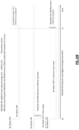
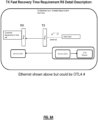
- FIG. 9 shows a diagram for the Tx (off-ramp) direction recovery which like Rx direction must recover fast.
- the connection is electrical and signal sourced.
- the transceiver TX path must all recover from a TX unstable electrical signal event at the host electrical input interface (clock transient, framing transient) in ⁇ 10ms.
- Link budget Support a link that allows for up to about a 6 to 18 dB loss between plugs (channel Insertion loss)
- TPT For TPT we need laser fast off and fast on -
- the TPT (Y-Cable) switch is performed by turning lasers off on the current active card and then on the newly active card, must provide mechanism to shut laser off or on within 10ms (I2C register or SerDes Fast Tx Squelch)
- TX Fast Recovery Time - The transceiver Tx path shall recover from a Tx unstable signal event at the host electrical input interface (clock transient, framing transient) in ⁇ 10ms.
- TPT For TPT, there is a requirement for the Tx side to turn off and on fast.
- the fast turn off and on requirement is used when one Tx line is active but experiencing errors that causes a protection switch. As seen in FIGS. 5 and 7 , the active client Tx has to be turned off at time t0 and the stand-by client Tx has to be turned on.
- the fast Tx off/on requirement in TPT is since both Tx are connected to the Rx. This is not the case in the OPS, where only one Tx line is connected. Thus, there is not necessarily a requirement for fast off/on in the OPS configuration.
- fast can be on the order of 10ms, i.e., on or off in about 10ms.
- 10ms i.e., on or off in about 10ms.
- the protection scheme is configured to switch between the client Tx lines based on specific criteria.
- the Rx DSP 20 may not know which line it is receiving, but it does experience a time where there is no traffic, the present disclosure holds off any reacquisition at the Rx DSP 20 during this time, to hopefully enable a quick switch as any reacquisition would take seconds.
- This Rx DSP functionality is independent of the underlying protection scheme.
- Rx recovery requirements are the same for OPS and TPT.
- the key here is the ability to withstand some period of poor traffic without causing some signal reacquisition that can take seconds.
- the protection switch is performed by an OPS module 10 or equivalent where a 1x2 switch selects one of the two client Tx lines.
- the selection can be based on power, LOS, LOL, bit error rates, explicit commands, etc.
- t0 to t1 delta there is a time period (t0 to t1 delta) where the Rx DSP 20 does not have light / traffic.
- the protection switch is actually performed at the client Tx or based on a break in one of the client Tx lines, since the TPT module 30 or equivalent includes a coupler connecting both client Tx lines to the Rx.
- the Rx DSP 20 For the fast Rx recovery, there is a requirement for the Rx DSP 20 to identify a signature so that it knows a protection switch is occurring to let the Rx DSP 20 know so that it can start the fast Rx recovery process which basically includes holding off any reacquisition and LOS/LOL reporting. As such, the Rx DSP 20 is configured to holdoff reacquisition and LOS/LOL reporting for some time period.
- this can be a configurable aspect, i.e., the Rx DSP 20 is in a fast mode configuration. For example, this can be signaled using vendor user space bytes to the Rx DSP 20 or through some other configuration.
- the signature can include - Rx Signature on switch (t0 to t1 delta), see FIG. 5B .
- the Rx DSP 20 is configured to detect this signature when the fast switch mode is enabled. And upon detection, the Rx DSP 20 enters the fast switch mode performing configuration settings and LOS/LOL holdoff until a predetermined period.
- the Rx DSP 20 fast recovery should be within 10ms after receiving good traffic.
- 400GigE can use FEC transparent monitor mode for Rx LOL detect, e.g., AM unlock for fast detect.
- the Rx recovery modes can be defined in a 100G, 400G, etc. module EEPROM vendor user space bytes.
- the fast Rx recovery support advertising bits can include Fast Rx Auto Mode Supported [ON/OFF] and/or Fast Rx Manual Mode Supported [ON/OFF].
- Rx Recovery Control Bits can include 3 settings: Standards compliant Rx recovery; Fast Rx Auto Mode; Fast Rx Manual Mode.
- Fast Rx Manual Mode Setting bits can include Tx1/Tx2 source select (default Tx1); Rx DSP settings for Tx1; and Rx DSP settings for Tx2. Further control bits include (DSP adaptation hold off (0 to 1 second), LOS reporting holdoff (0 to 1 second).
- the fast Rx recovery mode should be about 10ms after good traffic (stable signal).
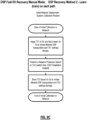
- a Fast RX Auto Mode includes DSP recovery methods 1&3.
- a Fast Rx Manual Mode includes a DSP recovery method 2.
- Method 1 Default starting point (good enough to carry traffic but not necessarily optimal). When transient occurs, use default and allow optimization/training after. Default values could be Vendor Standard across all plugs or factory calibrated.
- Method 2 Can learn (train) on each path to determine any DSP recovery values (stored Tx1 and Tx2 values).
- the Fast RX Recovery Method will require a Manual Fast Module Rx Recovery Calibration procedure to determine and store the optimal Rx DSP settings required for both Tx1 and Tx2. This calibration procedure will be performed at System level. To complement the system level calibration there is also a Module level post calibration procedure when in manual mode. See FIGS. 9B and 9C . This post calibration allows for automatic TX1 /TX2 calibration to occur if the system level calibration did not occur or occur properly for some reason.
- Method 3 Holdover mechanism: Use values from Tx switched away from (e.g., Tx1 if switching to Tx2).
- a provisionable adaptation holdoff can be 0 to 1 sec in steps of 100ms, as well as other values. This can include a Provisionable Plug Holdoff LOS/LOL reporting (avoids host equipment acting on these faults before adaptation holdoff is complete
- Fast Fault Detect Technique 1 Use FEC/PCS block within DSP for Ethernet rates - For Ethernet rates use physical coding sublayer (PCS)/ forward error correction (FEC) block within DSP (examples as follows):
- Host card detects fault (via framer) and drives reserved pin for fast notification to DSP. This would solve the issue where the plug LOS/LOL detect via I2C is too slow (100ms max). OTU4 does not have the FEC transparent monitor option
- the Rx DSP 20 detects the fast switch mode, the Rx has to either maintain or change its configuration settings.
- the Rx DSP 20 is first getting light from a working Tx client link, stops getting light and detects the fast switch mode, and then starts getting from a protection Tx client link.
- the Rx DSP 20 may have to do something to change its settings from the working Tx client link and the protection Tx client link.
- the terms "working Tx client link” and "protection Tx client link” are used for illustration. These can be any types of fiber links.
- the optical module e.g., pluggable
- the optical module will have 2 fast recovery option modes as shown in FIGS. 5A and 5B (Fast Rx Auto Mode and Fast Rx Manual Mode). In manual mode it will have capability to store TX1 and TX2 settings.
- the Rx DSP 20 can start signal acquisition. Bad traffic may be based on some BER threshold or the link. Also, after expiration of the adaptation holdoff and bad traffic, the Rx DSP 20 can report LOS/LOL so that any host equipment can start acting on these faults.
- Traffic interruption detection for fast recovery will likely need to come from the Rx DSP 20 and not rely on the plug Optical LOS as that may be too slow for detection.
- Another way to improve Rx recovery time is to use two transmitters configured to function with the same Rx settings, either through calibration, adjustment at provisioning, or periodic adjustment of Tx parameters.
- One such approach is to select two transmitters that provide similar eyes so that there is no need for adjustment. For example, this could include similar transmitters such as a same module from the same vendor.
- the transmitters can be configured to operate with common Rx settings.
- FIG. 8 is a flowchart of a process 100 implementable by circuitry such as a Rx DSP 20.
- the process 100 includes detecting traffic is interrupted on a current link associated with the optical receiver (step 102), entering a holdoff period (step 104), and one of i) receiving good traffic during the holdoff period and ii) having the holdoff period expire that causes a notification to a host device and retrain to acquire an optical signal (step 106).
- the process 100 can further include, responsive to the holdoff period, refrain from a retrain to the optical signal and refrain from any notification to the host device (step 108).
- the process 100 can further include, responsive to the holdoff period, change settings for the optical signal to one of default settings and predetermined settings for a new link (step 110). Settings for an optical signal can be maintained during the holdoff period.
- the notification can include any of loss of signal (LOS) and loss of light (LOL).
- the process 100 can further include receive a configuration for a fast switch mode whereby the holdoff period is used.
- the process 100 can further include, responsive to the good traffic during the holdoff period, continue to process the good traffic and retrain on the optical signal while the good traffic is processed (step 112).
- the optical receiver can be connected to an optical protection switch (OPS).
- OPS optical protection switch
- the optical receiver can be connected to an optical coupler whereby two different links including the current link are capable of sending the optical signal; this can be the TPT.
- Corresponding optical transmitters on the two different links can be configured for fast turn off and turn on.
- the optical signal can include non-return-to-zero (NRZ) modulation, pulse amplitude modulation (PAM), or coherent modulation.
- NRZ non-return-to-zero
- PAM pulse amplitude modulation
- Tx Fast Recovery Requirement means the transceiver Tx path shall recover in ⁇ 10ms from a Tx unstable event at the host electrical input interface (clock transient, framing transient). Vendor Optional, if required: Similar to Rx Fast Recovery Modes described previously, a fast Tx Recovery Mode can be implemented if required and where appropriate.
- processors such as microprocessors; Central Processing Units (CPUs); Digital Signal Processors (DSPs): customized processors such as Network Processors (NPs) or Network Processing Units (NPUs), Graphics Processing Units (GPUs), or the like; Field-Programmable Gate Arrays (FPGAs); and the like along with unique stored program instructions (including both software and firmware) for control thereof to implement, in conjunction with certain non-processor circuits, some, most, or all of the functions of the methods and/or systems described herein.
- processors such as microprocessors; Central Processing Units (CPUs); Digital Signal Processors (DSPs): customized processors such as Network Processors (NPs) or Network Processing Units (NPUs), Graphics Processing Units (GPUs), or the like; Field-Programmable Gate Arrays (FPGAs); and the like along with unique stored program instructions (including both software and firmware) for control thereof to implement, in conjunction with certain non-processor circuits, some, most, or all
- circuitry configured to
- logic configured to
- some embodiments may include a non-transitory computer-readable medium having instructions stored thereon for programming a computer, server, appliance, device, at least one processor, circuit/circuitry, etc. to perform functions as described and claimed herein.
- Examples of such non-transitory computer-readable medium include, but are not limited to, a hard disk, an optical storage device, a magnetic storage device, a Read-Only Memory (ROM), a Programmable ROM (PROM), an Erasable PROM (EPROM), an Electrically EPROM (EEPROM), Flash memory, and the like.
- software can include instructions executable by one or more processors (e.g., any type of programmable circuitry or logic) that, in response to such execution, cause the one or more processors to perform a set of operations, steps, methods, processes, algorithms, functions, techniques, etc. as described herein for the various embodiments.
- processors e.g., any type of programmable circuitry or logic
Landscapes
- Physics & Mathematics (AREA)
- Electromagnetism (AREA)
- Engineering & Computer Science (AREA)
- Computer Networks & Wireless Communication (AREA)
- Signal Processing (AREA)
- Optical Communication System (AREA)
Claims (15)
- Digitaler Rx-Empfänger-Signalprozessor, DSP, (20) in einem optischen Empfänger, wobei der Rx-DSP (20) eine Schaltungsanordnung umfasst, die konfiguriert ist, umzu erfassen (102), dass der Verkehr auf einer aktuellen Verbindung, die dem optischen Empfänger zugeordnet ist, unterbrochen ist,in eine Holdoff-Periode einzutreten (104), in der kein Signalverlust, LOS, oder Lichtverlust, LOL, gemeldet wird, während ein optisches Signal, das dem Verkehr zugeordnet ist, i) zu einer neuen Verbindung umgeschaltet wird oder ii) sich von der Unterbrechung auf der aktuellen Verbindung erholt, undeines (106) von i) Empfangen des Verkehrs während der Holdoff-Periode oder ii) Ablaufenlassen der Holdoff-Periode, das a) eine Bekanntgabe an eine Host-Vorrichtung und b) erneutes Trainieren des Rx-DSP (20) veranlasst, um dessen optisches Signal zu erheben, um den Verkehr auf der neuen Verbindung oder der aktuellen Verbindung zu empfangen, wobei der RX-DSP (20) neu trainiert wird, um verschiedene Einstellungen auf dem optischen Empfänger zu bestimmen.
- Rx-DSP (20) nach Anspruch 1, wobei die Schaltungsanordnung konfiguriert ist, um
während der Holdoff-Periode von einem erneuten Trainieren zum Erheben des optischen Signals abzusehen (108) und von jeder Bekanntgabe an die Host-Vorrichtung abzusehen. - Rx-DSP (20) nach einem der Ansprüche 1 bis 2, wobei die Schaltungsanordnung konfiguriert ist, um
Einstellungen (110) nach dem Eintreten in die Holdoff-Periode für das optische Signal auf eine von Standardeinstellungen und vorbestimmten Einstellungen für die neue Verbindung zu ändern. - Rx-DSP (20) nach einem der Ansprüche 1 bis 2, wobei Einstellungen für das optische Signal während der Holdoff-Periode aufrechterhalten werden.
- Rx-DSP (20) nach einem der Ansprüche 1 bis 4, wobei die Bekanntgabe eines oder mehrere von Signalverlust, LOS, und Lichtverlust, LOL, beinhaltet.
- Rx-DSP (20) nach einem der Ansprüche 1 bis 5, wobei die Schaltungsanordnung weiter konfiguriert ist, um
eine Konfiguration zu empfangen, wodurch die Holdoff-Periode verwendet wird. - Rx-DSP (20) nach einem der Ansprüche 1 bis 6, wobei die Schaltungsanordnung weiter konfiguriert ist, um
als Reaktion (112) auf das Empfangen des Verkehrs während der Holdoff-Periode, das Verarbeiten des Verkehrs und erneute Trainieren an dem optischen Signal fortzusetzen, während der Verkehr verarbeitet wird. - Rx-DSP (20) nach einem der Ansprüche 1 bis 7, wobei der optische Empfänger mit einem optischen Schutzschalter (OPS) verbunden ist.
- Rx-DSP (20) nach einem der Ansprüche 1 bis 7, wobei der optische Empfänger mit einem optischen Koppler verbunden ist, wodurch zwei unterschiedliche Verbindungen, die die aktuelle Verbindung beinhalten, in der Lage sind, das optische Signal zu senden.
- Rx-DSP (20) nach Anspruch 9, wobei entsprechende optische Sender an den zwei unterschiedlichen Verbindungen dazu konfiguriert sind, schnell aus- und einzuschalten.
- Rx-DSP (20) nach einem der Ansprüche 1 bis 10, wobei das optische Signal eine Non-Return-to-Zero-Modulation (NRZ-Modulation) beinhaltet.
- Rx-DSP (20) nach einem der Ansprüche 1 bis 10, wobei das optische Signal eine Pulsamplitudenmodulation, PAM, beinhaltet.
- Rx-DSP (20) nach einem der Ansprüche 1 bis 10, wobei das optische Signal eine kohärente Modulation beinhaltet.
- Rx-DSP (20) nach einem der Ansprüche 1 bis 13, wobei Einstellungen eines Senders für die aktuelle Verbindung und eines Senders für die Schutzverbindung derart eingestellt sind, dass kein Bedarf an Einstellen des Rx-DSP beim Umschalten zwischen Verbindungen besteht.
- Verfahren (100) das in einem digitalen Rx-Empfänger-Signalprozessor, DSP, (20) in einem optischen Empfänger umgesetzt wird, wobei das Verfahren die folgenden Schritte umfasst:Erfassen (102), dass der Verkehr auf einer aktuellen Verbindung, die dem optischen Empfänger zugeordnet ist, unterbrochen ist,Eintreten in eine Holdoff-Periode (104), in der kein Signalverlust, LOS, oder Lichtverlust, LOL, gemeldet wird, während ein optisches Signal, das dem Verkehr zugeordnet ist, i) zu einer neuen Verbindung umgeschaltet wird oder ii) sich von der Unterbrechung auf der aktuellen Verbindung erholt, undeines (106) von i) Empfangen des Verkehrs während der Holdoff-Periode oder ii) Ablaufenlassen der Holdoff-Periode, das a) eine Bekanntgabe an eine Host-Vorrichtung und b) erneutes Trainieren des Rx-DSP (20) veranlasst, um ein optisches Signal zu erheben, um den Verkehr auf der neuen Verbindung oder der aktuellen Verbindung zu empfangen, wobei das erneute Trainieren das Bestimmen verschiedener Einstellungen auf dem optischen Empfänger beinhaltet.
Applications Claiming Priority (2)
| Application Number | Priority Date | Filing Date | Title |
|---|---|---|---|
| US202163272133P | 2021-10-26 | 2021-10-26 | |
| PCT/US2022/047838 WO2023076347A1 (en) | 2021-10-26 | 2022-10-26 | Fast optical receiver recovery on client side using optical interconnects with dsps |
Publications (2)
| Publication Number | Publication Date |
|---|---|
| EP4205305A1 EP4205305A1 (de) | 2023-07-05 |
| EP4205305B1 true EP4205305B1 (de) | 2024-02-07 |
Family
ID=84363728
Family Applications (1)
| Application Number | Title | Priority Date | Filing Date |
|---|---|---|---|
| EP22813794.9A Active EP4205305B1 (de) | 2021-10-26 | 2022-10-26 | Schnelle optische empfängerwiederherstellung auf client-seite unter verwendung optischer verbindungen mit dsps |
Country Status (5)
| Country | Link |
|---|---|
| US (2) | US12113579B2 (de) |
| EP (1) | EP4205305B1 (de) |
| CN (1) | CN118160243B (de) |
| CA (1) | CA3216038A1 (de) |
| WO (1) | WO2023076347A1 (de) |
Families Citing this family (1)
| Publication number | Priority date | Publication date | Assignee | Title |
|---|---|---|---|---|
| US12381624B2 (en) | 2023-06-27 | 2025-08-05 | Ciena Corporation | Signal-to-noise ratio-based bit error ratio calculation for reporting beyond a forward error correction threshold |
Family Cites Families (42)
| Publication number | Priority date | Publication date | Assignee | Title |
|---|---|---|---|---|
| CA2065558C (en) | 1992-04-08 | 1999-06-15 | David John Nicholson | Communications system with a single protection loop |
| US5365510A (en) | 1992-04-09 | 1994-11-15 | Northern Telecom Limited | Communications system with a single protection loop |
| US6761999B2 (en) | 1996-07-08 | 2004-07-13 | The Regents Of The University Of California | Nondegenerate four-wave mixing using photoinduced charge-transfer materials |
| US5838924A (en) * | 1996-08-06 | 1998-11-17 | Lucent Technologies Inc | Asynchronous transfer mode (ATM) connection protection switching apparatus and method |
| US7065298B1 (en) | 1998-11-17 | 2006-06-20 | Intel Corporation | Code-based optical networks, methods, and apparatus |
| US6650618B1 (en) | 1999-07-01 | 2003-11-18 | Nortel Networks Limited | Method and apparatus for managing communications between nodes in a bi-directional ring network |
| US6952396B1 (en) | 1999-09-27 | 2005-10-04 | Nortel Networks Limited | Enhanced dual counter rotating ring network control system |
| US7203151B2 (en) | 1999-10-05 | 2007-04-10 | Intel Corporation | Spatially-spectrally swept optical memories and addressing methods |
| IL132727A (en) | 1999-11-03 | 2003-11-23 | Eci Telecom Ltd | Method and system for diverting communication to a protection path in an optical communication network |
| US6313771B1 (en) | 1999-11-17 | 2001-11-06 | Templex Technology, Inc. | Codes, methods, and apparatus for optical encoding and decoding |
| CA2322905A1 (en) | 1999-11-17 | 2001-05-17 | Nortel Networks Corporation | Methods and devices for adding and removing data from serial data streams |
| US20010046074A1 (en) * | 2000-05-25 | 2001-11-29 | Sunao Kakizaki | Protection switching apparatus for 1 + 1 optical transmission lines |
| US6646790B2 (en) | 2002-01-28 | 2003-11-11 | Nortel Networks Limited | Optical amplifier gain control monitoring |
| US7483450B1 (en) | 2002-03-08 | 2009-01-27 | Nortel Networks Limited | Method and system for link-based clock synchronization in asynchronous networks |
| US6842561B2 (en) | 2002-03-29 | 2005-01-11 | Nortel Networks Limited | Optical performance monitoring scheme |
| US7508846B2 (en) | 2002-11-22 | 2009-03-24 | Nortel Networks Ltd. | Physical capacity aggregation system and method |
| US7433603B2 (en) | 2002-12-13 | 2008-10-07 | Intel Corporation | Using active and passive optical components for an optical network |
| US7369514B1 (en) | 2003-06-18 | 2008-05-06 | Nortel Networks Limited | Source credit based fairness scheme |
| US20060013133A1 (en) | 2004-07-16 | 2006-01-19 | Wang-Hsin Peng | Packet-aware time division multiplexing switch with dynamically configurable switching fabric connections |
| US7467056B2 (en) | 2007-03-09 | 2008-12-16 | Nortel Networks Limited | Method and apparatus for aligning multiple outputs of an FPGA |
| US9319758B2 (en) * | 2008-10-21 | 2016-04-19 | Broadcom Corporation | Method and system for protection switching in ethernet passive optical networks |
| US8948313B2 (en) | 2010-01-20 | 2015-02-03 | LG-Erricsson Co., Ltd. | Method and apparatus for adjusting a symbol decision threshold at a receiver in a communication network |
| US9100116B2 (en) | 2011-08-24 | 2015-08-04 | Ciena Corporation | Short-term optical recovery systems and methods for coherent optical receivers |
| JP5970943B2 (ja) * | 2012-05-01 | 2016-08-17 | 富士通株式会社 | 光伝送装置、及び光伝送方法 |
| US9088380B2 (en) | 2012-05-31 | 2015-07-21 | Ciena Corporation | Optical transport network generic non-client specific protection systems and methods |
| US10637604B2 (en) | 2014-10-24 | 2020-04-28 | Ciena Corporation | Flexible ethernet and multi link gearbox mapping procedure to optical transport network |
| US9806801B2 (en) | 2015-11-03 | 2017-10-31 | Ciena Corporation | In-service optical fault isolation systems and methods |
| US9793984B2 (en) | 2016-01-20 | 2017-10-17 | Ciena Corporation | Coherent receiver based virtual optical spectrum analyzer |
| US10944478B2 (en) * | 2016-04-12 | 2021-03-09 | Cable Television Laboratories, Inc. | Fiber communication systems and methods |
| US10097262B2 (en) | 2016-11-30 | 2018-10-09 | Ciena Corporation | Client protection switch in optical pluggable transceivers activated through fast electrical data squelch |
| US10382167B2 (en) | 2016-12-13 | 2019-08-13 | Ciena Corporation | Flexible ethernet enhanced forward error correction |
| US10348410B1 (en) | 2018-04-24 | 2019-07-09 | Ciena Corporation | Adaptive optical modem configuration based on operating conditions |
| US10826601B2 (en) * | 2019-01-16 | 2020-11-03 | Ciena Corporation | Optical switch with path continuity monitoring for optical protection switching |
| US10852497B2 (en) | 2019-02-27 | 2020-12-01 | Ciena Corporation | Pluggable optical module thermal management and heat shield assemblies, devices, and methods |
| US11082367B2 (en) | 2019-05-10 | 2021-08-03 | Ciena Corporation | FlexE frame format using 256b/257b block encoding |
| US10985837B2 (en) | 2019-06-17 | 2021-04-20 | Ciena Corporation | Generic non-client specific protection via TCM status and enhanced OTN network propagation of client faults |
| US10877230B1 (en) | 2019-10-18 | 2020-12-29 | Ciena Corporation | Thermal control system with sliding heatsink resistance control for pluggable optics in a hardened optical platform |
| US11026001B1 (en) | 2019-12-05 | 2021-06-01 | Ciena Corporation | Systems and methods for increasing granularity and fan-out of electric circuits with co-packaged optical interfaces |
| US11309984B2 (en) | 2020-03-04 | 2022-04-19 | Ciena Corporation | TCM control for physical layer on OTU ports |
| US10979139B1 (en) | 2020-03-31 | 2021-04-13 | Ciena Corporation | Optical protection devices having passive splitter/couplers and built-in interrupters |
| US11101882B1 (en) | 2020-06-17 | 2021-08-24 | Ciena Corporation | Low order regenerator with high order traffic conditioning in optical transport network |
| US11099339B1 (en) | 2020-06-30 | 2021-08-24 | Ciena Corporation | Management interface handler to expedite module boot time in pluggable optical modules |
-
2022
- 2022-10-26 WO PCT/US2022/047838 patent/WO2023076347A1/en not_active Ceased
- 2022-10-26 US US17/973,849 patent/US12113579B2/en active Active
- 2022-10-26 CA CA3216038A patent/CA3216038A1/en active Pending
- 2022-10-26 CN CN202280072468.4A patent/CN118160243B/zh active Active
- 2022-10-26 EP EP22813794.9A patent/EP4205305B1/de active Active
-
2024
- 2024-09-06 US US18/826,276 patent/US20240430013A1/en active Pending
Also Published As
| Publication number | Publication date |
|---|---|
| EP4205305A1 (de) | 2023-07-05 |
| CN118160243A (zh) | 2024-06-07 |
| CN118160243B (zh) | 2025-03-11 |
| US20230127848A1 (en) | 2023-04-27 |
| US20240430013A1 (en) | 2024-12-26 |
| CA3216038A1 (en) | 2023-05-04 |
| US12113579B2 (en) | 2024-10-08 |
| WO2023076347A1 (en) | 2023-05-04 |
Similar Documents
| Publication | Publication Date | Title |
|---|---|---|
| US8090258B2 (en) | Method and apparatus for correcting faults in a passive optical network | |
| US10305605B2 (en) | Optical receiver, optical transceiver comprising the same, and method of protecting a photodetector in the optical receiver with a transient event or a transient state determination | |
| US10396891B2 (en) | Client protection switch in optical pluggable transceivers activated through fast electrical data squelch | |
| US7809275B2 (en) | XFP transceiver with 8.5G CDR bypass | |
| US20130073749A1 (en) | Backchannel communication between host and interface module | |
| US20120063295A1 (en) | PHY Retraining | |
| US8499103B2 (en) | Converter device to convert between different small form factor pluggable standards | |
| US20090010643A1 (en) | Method and apparatus for identifying faults in a passive optical network | |
| CN101978703A (zh) | 用于无源光网络的快速保护方案 | |
| US20240430013A1 (en) | Fast optical receiver recovery on client side using optical interconnects with DSPs | |
| US20260019149A1 (en) | Messaging Channel in a Coherent Optical DSP Frame | |
| US20260113137A1 (en) | Out-Of-Band Based Independent Link Training Of In-Band Links Between Host Devices And Optical Modules | |
| CN115643503A (zh) | 一种光模块配置方法以及装置 | |
| CN101141218B (zh) | 用于波分复用承载客户网的保护倒换系统及方法 | |
| JP2008294752A (ja) | 光データリンク及び補償係数調整方法 | |
| US9002195B2 (en) | Solution for hitless protection in high-speed OTN framer and front-end | |
| CN101783975B (zh) | 通信网络中的测距方法、装置及系统 | |
| US20060215782A1 (en) | Methods and apparatus for asynchronous serial channel connections in communication systems | |
| JP2009081800A (ja) | 加入者宅側光回線終端装置 | |
| CN102684955B (zh) | 1G Ethernet与OC48网络自适应接入系统和方法 | |
| WO2025247045A9 (zh) | 一种故障定位方法及装置 | |
| TW202245446A (zh) | 網路裝置之操作方法及網路裝置之控制晶片 | |
| JP2018050117A (ja) | 光受信装置及び閾値調整方法 |
Legal Events
| Date | Code | Title | Description |
|---|---|---|---|
| STAA | Information on the status of an ep patent application or granted ep patent |
Free format text: STATUS: UNKNOWN |
|
| STAA | Information on the status of an ep patent application or granted ep patent |
Free format text: STATUS: THE INTERNATIONAL PUBLICATION HAS BEEN MADE |
|
| PUAI | Public reference made under article 153(3) epc to a published international application that has entered the european phase |
Free format text: ORIGINAL CODE: 0009012 |
|
| STAA | Information on the status of an ep patent application or granted ep patent |
Free format text: STATUS: REQUEST FOR EXAMINATION WAS MADE |
|
| 17P | Request for examination filed |
Effective date: 20230329 |
|
| AK | Designated contracting states |
Kind code of ref document: A1 Designated state(s): AL AT BE BG CH CY CZ DE DK EE ES FI FR GB GR HR HU IE IS IT LI LT LU LV MC ME MK MT NL NO PL PT RO RS SE SI SK SM TR |
|
| STAA | Information on the status of an ep patent application or granted ep patent |
Free format text: STATUS: EXAMINATION IS IN PROGRESS |
|
| 17Q | First examination report despatched |
Effective date: 20230714 |
|
| P01 | Opt-out of the competence of the unified patent court (upc) registered |
Effective date: 20231004 |
|
| GRAP | Despatch of communication of intention to grant a patent |
Free format text: ORIGINAL CODE: EPIDOSNIGR1 |
|
| STAA | Information on the status of an ep patent application or granted ep patent |
Free format text: STATUS: GRANT OF PATENT IS INTENDED |
|
| DAV | Request for validation of the european patent (deleted) | ||
| DAX | Request for extension of the european patent (deleted) | ||
| GRAS | Grant fee paid |
Free format text: ORIGINAL CODE: EPIDOSNIGR3 |
|
| GRAA | (expected) grant |
Free format text: ORIGINAL CODE: 0009210 |
|
| STAA | Information on the status of an ep patent application or granted ep patent |
Free format text: STATUS: THE PATENT HAS BEEN GRANTED |
|
| INTG | Intention to grant announced |
Effective date: 20231212 |
|
| AK | Designated contracting states |
Kind code of ref document: B1 Designated state(s): AL AT BE BG CH CY CZ DE DK EE ES FI FR GB GR HR HU IE IS IT LI LT LU LV MC ME MK MT NL NO PL PT RO RS SE SI SK SM TR |
|
| REG | Reference to a national code |
Ref country code: GB Ref legal event code: FG4D |
|
| REG | Reference to a national code |
Ref country code: CH Ref legal event code: EP |
|
| REG | Reference to a national code |
Ref country code: DE Ref legal event code: R096 Ref document number: 602022001877 Country of ref document: DE |
|
| REG | Reference to a national code |
Ref country code: IE Ref legal event code: FG4D |
|
| REG | Reference to a national code |
Ref country code: NL Ref legal event code: FP |
|
| REG | Reference to a national code |
Ref country code: LT Ref legal event code: MG9D |
|
| PG25 | Lapsed in a contracting state [announced via postgrant information from national office to epo] |
Ref country code: IS Free format text: LAPSE BECAUSE OF FAILURE TO SUBMIT A TRANSLATION OF THE DESCRIPTION OR TO PAY THE FEE WITHIN THE PRESCRIBED TIME-LIMIT Effective date: 20240607 |
|
| PG25 | Lapsed in a contracting state [announced via postgrant information from national office to epo] |
Ref country code: LT Free format text: LAPSE BECAUSE OF FAILURE TO SUBMIT A TRANSLATION OF THE DESCRIPTION OR TO PAY THE FEE WITHIN THE PRESCRIBED TIME-LIMIT Effective date: 20240207 |
|
| PG25 | Lapsed in a contracting state [announced via postgrant information from national office to epo] |
Ref country code: GR Free format text: LAPSE BECAUSE OF FAILURE TO SUBMIT A TRANSLATION OF THE DESCRIPTION OR TO PAY THE FEE WITHIN THE PRESCRIBED TIME-LIMIT Effective date: 20240508 |
|
| REG | Reference to a national code |
Ref country code: AT Ref legal event code: MK05 Ref document number: 1656023 Country of ref document: AT Kind code of ref document: T Effective date: 20240207 |
|
| PG25 | Lapsed in a contracting state [announced via postgrant information from national office to epo] |
Ref country code: HR Free format text: LAPSE BECAUSE OF FAILURE TO SUBMIT A TRANSLATION OF THE DESCRIPTION OR TO PAY THE FEE WITHIN THE PRESCRIBED TIME-LIMIT Effective date: 20240207 Ref country code: RS Free format text: LAPSE BECAUSE OF FAILURE TO SUBMIT A TRANSLATION OF THE DESCRIPTION OR TO PAY THE FEE WITHIN THE PRESCRIBED TIME-LIMIT Effective date: 20240507 |
|
| PG25 | Lapsed in a contracting state [announced via postgrant information from national office to epo] |
Ref country code: ES Free format text: LAPSE BECAUSE OF FAILURE TO SUBMIT A TRANSLATION OF THE DESCRIPTION OR TO PAY THE FEE WITHIN THE PRESCRIBED TIME-LIMIT Effective date: 20240207 |
|
| PG25 | Lapsed in a contracting state [announced via postgrant information from national office to epo] |
Ref country code: AT Free format text: LAPSE BECAUSE OF FAILURE TO SUBMIT A TRANSLATION OF THE DESCRIPTION OR TO PAY THE FEE WITHIN THE PRESCRIBED TIME-LIMIT Effective date: 20240207 |
|
| PG25 | Lapsed in a contracting state [announced via postgrant information from national office to epo] |
Ref country code: RS Free format text: LAPSE BECAUSE OF FAILURE TO SUBMIT A TRANSLATION OF THE DESCRIPTION OR TO PAY THE FEE WITHIN THE PRESCRIBED TIME-LIMIT Effective date: 20240507 Ref country code: NO Free format text: LAPSE BECAUSE OF FAILURE TO SUBMIT A TRANSLATION OF THE DESCRIPTION OR TO PAY THE FEE WITHIN THE PRESCRIBED TIME-LIMIT Effective date: 20240507 Ref country code: LT Free format text: LAPSE BECAUSE OF FAILURE TO SUBMIT A TRANSLATION OF THE DESCRIPTION OR TO PAY THE FEE WITHIN THE PRESCRIBED TIME-LIMIT Effective date: 20240207 Ref country code: IS Free format text: LAPSE BECAUSE OF FAILURE TO SUBMIT A TRANSLATION OF THE DESCRIPTION OR TO PAY THE FEE WITHIN THE PRESCRIBED TIME-LIMIT Effective date: 20240607 Ref country code: HR Free format text: LAPSE BECAUSE OF FAILURE TO SUBMIT A TRANSLATION OF THE DESCRIPTION OR TO PAY THE FEE WITHIN THE PRESCRIBED TIME-LIMIT Effective date: 20240207 Ref country code: GR Free format text: LAPSE BECAUSE OF FAILURE TO SUBMIT A TRANSLATION OF THE DESCRIPTION OR TO PAY THE FEE WITHIN THE PRESCRIBED TIME-LIMIT Effective date: 20240508 Ref country code: FI Free format text: LAPSE BECAUSE OF FAILURE TO SUBMIT A TRANSLATION OF THE DESCRIPTION OR TO PAY THE FEE WITHIN THE PRESCRIBED TIME-LIMIT Effective date: 20240207 Ref country code: ES Free format text: LAPSE BECAUSE OF FAILURE TO SUBMIT A TRANSLATION OF THE DESCRIPTION OR TO PAY THE FEE WITHIN THE PRESCRIBED TIME-LIMIT Effective date: 20240207 Ref country code: BG Free format text: LAPSE BECAUSE OF FAILURE TO SUBMIT A TRANSLATION OF THE DESCRIPTION OR TO PAY THE FEE WITHIN THE PRESCRIBED TIME-LIMIT Effective date: 20240207 Ref country code: AT Free format text: LAPSE BECAUSE OF FAILURE TO SUBMIT A TRANSLATION OF THE DESCRIPTION OR TO PAY THE FEE WITHIN THE PRESCRIBED TIME-LIMIT Effective date: 20240207 |
|
| PG25 | Lapsed in a contracting state [announced via postgrant information from national office to epo] |
Ref country code: PT Free format text: LAPSE BECAUSE OF FAILURE TO SUBMIT A TRANSLATION OF THE DESCRIPTION OR TO PAY THE FEE WITHIN THE PRESCRIBED TIME-LIMIT Effective date: 20240607 Ref country code: PL Free format text: LAPSE BECAUSE OF FAILURE TO SUBMIT A TRANSLATION OF THE DESCRIPTION OR TO PAY THE FEE WITHIN THE PRESCRIBED TIME-LIMIT Effective date: 20240207 |
|
| PG25 | Lapsed in a contracting state [announced via postgrant information from national office to epo] |
Ref country code: SE Free format text: LAPSE BECAUSE OF FAILURE TO SUBMIT A TRANSLATION OF THE DESCRIPTION OR TO PAY THE FEE WITHIN THE PRESCRIBED TIME-LIMIT Effective date: 20240207 Ref country code: PT Free format text: LAPSE BECAUSE OF FAILURE TO SUBMIT A TRANSLATION OF THE DESCRIPTION OR TO PAY THE FEE WITHIN THE PRESCRIBED TIME-LIMIT Effective date: 20240607 Ref country code: PL Free format text: LAPSE BECAUSE OF FAILURE TO SUBMIT A TRANSLATION OF THE DESCRIPTION OR TO PAY THE FEE WITHIN THE PRESCRIBED TIME-LIMIT Effective date: 20240207 Ref country code: LV Free format text: LAPSE BECAUSE OF FAILURE TO SUBMIT A TRANSLATION OF THE DESCRIPTION OR TO PAY THE FEE WITHIN THE PRESCRIBED TIME-LIMIT Effective date: 20240207 |
|
| PG25 | Lapsed in a contracting state [announced via postgrant information from national office to epo] |
Ref country code: DK Free format text: LAPSE BECAUSE OF FAILURE TO SUBMIT A TRANSLATION OF THE DESCRIPTION OR TO PAY THE FEE WITHIN THE PRESCRIBED TIME-LIMIT Effective date: 20240207 |
|
| PG25 | Lapsed in a contracting state [announced via postgrant information from national office to epo] |
Ref country code: SM Free format text: LAPSE BECAUSE OF FAILURE TO SUBMIT A TRANSLATION OF THE DESCRIPTION OR TO PAY THE FEE WITHIN THE PRESCRIBED TIME-LIMIT Effective date: 20240207 |
|
| PG25 | Lapsed in a contracting state [announced via postgrant information from national office to epo] |
Ref country code: CZ Free format text: LAPSE BECAUSE OF FAILURE TO SUBMIT A TRANSLATION OF THE DESCRIPTION OR TO PAY THE FEE WITHIN THE PRESCRIBED TIME-LIMIT Effective date: 20240207 Ref country code: EE Free format text: LAPSE BECAUSE OF FAILURE TO SUBMIT A TRANSLATION OF THE DESCRIPTION OR TO PAY THE FEE WITHIN THE PRESCRIBED TIME-LIMIT Effective date: 20240207 |
|
| PG25 | Lapsed in a contracting state [announced via postgrant information from national office to epo] |
Ref country code: SK Free format text: LAPSE BECAUSE OF FAILURE TO SUBMIT A TRANSLATION OF THE DESCRIPTION OR TO PAY THE FEE WITHIN THE PRESCRIBED TIME-LIMIT Effective date: 20240207 |
|
| PG25 | Lapsed in a contracting state [announced via postgrant information from national office to epo] |
Ref country code: SM Free format text: LAPSE BECAUSE OF FAILURE TO SUBMIT A TRANSLATION OF THE DESCRIPTION OR TO PAY THE FEE WITHIN THE PRESCRIBED TIME-LIMIT Effective date: 20240207 Ref country code: SK Free format text: LAPSE BECAUSE OF FAILURE TO SUBMIT A TRANSLATION OF THE DESCRIPTION OR TO PAY THE FEE WITHIN THE PRESCRIBED TIME-LIMIT Effective date: 20240207 Ref country code: RO Free format text: LAPSE BECAUSE OF FAILURE TO SUBMIT A TRANSLATION OF THE DESCRIPTION OR TO PAY THE FEE WITHIN THE PRESCRIBED TIME-LIMIT Effective date: 20240207 Ref country code: EE Free format text: LAPSE BECAUSE OF FAILURE TO SUBMIT A TRANSLATION OF THE DESCRIPTION OR TO PAY THE FEE WITHIN THE PRESCRIBED TIME-LIMIT Effective date: 20240207 Ref country code: DK Free format text: LAPSE BECAUSE OF FAILURE TO SUBMIT A TRANSLATION OF THE DESCRIPTION OR TO PAY THE FEE WITHIN THE PRESCRIBED TIME-LIMIT Effective date: 20240207 Ref country code: CZ Free format text: LAPSE BECAUSE OF FAILURE TO SUBMIT A TRANSLATION OF THE DESCRIPTION OR TO PAY THE FEE WITHIN THE PRESCRIBED TIME-LIMIT Effective date: 20240207 |
|
| REG | Reference to a national code |
Ref country code: DE Ref legal event code: R097 Ref document number: 602022001877 Country of ref document: DE |
|
| PG25 | Lapsed in a contracting state [announced via postgrant information from national office to epo] |
Ref country code: IT Free format text: LAPSE BECAUSE OF FAILURE TO SUBMIT A TRANSLATION OF THE DESCRIPTION OR TO PAY THE FEE WITHIN THE PRESCRIBED TIME-LIMIT Effective date: 20240207 |
|
| PLBE | No opposition filed within time limit |
Free format text: ORIGINAL CODE: 0009261 |
|
| STAA | Information on the status of an ep patent application or granted ep patent |
Free format text: STATUS: NO OPPOSITION FILED WITHIN TIME LIMIT |
|
| PG25 | Lapsed in a contracting state [announced via postgrant information from national office to epo] |
Ref country code: IT Free format text: LAPSE BECAUSE OF FAILURE TO SUBMIT A TRANSLATION OF THE DESCRIPTION OR TO PAY THE FEE WITHIN THE PRESCRIBED TIME-LIMIT Effective date: 20240207 |
|
| 26N | No opposition filed |
Effective date: 20241108 |
|
| PG25 | Lapsed in a contracting state [announced via postgrant information from national office to epo] |
Ref country code: SI Free format text: LAPSE BECAUSE OF FAILURE TO SUBMIT A TRANSLATION OF THE DESCRIPTION OR TO PAY THE FEE WITHIN THE PRESCRIBED TIME-LIMIT Effective date: 20240207 |
|
| PG25 | Lapsed in a contracting state [announced via postgrant information from national office to epo] |
Ref country code: MC Free format text: LAPSE BECAUSE OF FAILURE TO SUBMIT A TRANSLATION OF THE DESCRIPTION OR TO PAY THE FEE WITHIN THE PRESCRIBED TIME-LIMIT Effective date: 20240207 |
|
| PG25 | Lapsed in a contracting state [announced via postgrant information from national office to epo] |
Ref country code: LU Free format text: LAPSE BECAUSE OF NON-PAYMENT OF DUE FEES Effective date: 20241026 Ref country code: BE Free format text: LAPSE BECAUSE OF NON-PAYMENT OF DUE FEES Effective date: 20241031 |
|
| REG | Reference to a national code |
Ref country code: BE Ref legal event code: MM Effective date: 20241031 |
|
| PG25 | Lapsed in a contracting state [announced via postgrant information from national office to epo] |
Ref country code: IE Free format text: LAPSE BECAUSE OF NON-PAYMENT OF DUE FEES Effective date: 20241026 |
|
| PGFP | Annual fee paid to national office [announced via postgrant information from national office to epo] |
Ref country code: NL Payment date: 20251021 Year of fee payment: 4 |
|
| PGFP | Annual fee paid to national office [announced via postgrant information from national office to epo] |
Ref country code: DE Payment date: 20251021 Year of fee payment: 4 |
|
| PGFP | Annual fee paid to national office [announced via postgrant information from national office to epo] |
Ref country code: FR Payment date: 20251030 Year of fee payment: 4 |
|
| PG25 | Lapsed in a contracting state [announced via postgrant information from national office to epo] |
Ref country code: CY Free format text: LAPSE BECAUSE OF FAILURE TO SUBMIT A TRANSLATION OF THE DESCRIPTION OR TO PAY THE FEE WITHIN THE PRESCRIBED TIME-LIMIT; INVALID AB INITIO Effective date: 20221026 |
|
| PG25 | Lapsed in a contracting state [announced via postgrant information from national office to epo] |
Ref country code: HU Free format text: LAPSE BECAUSE OF FAILURE TO SUBMIT A TRANSLATION OF THE DESCRIPTION OR TO PAY THE FEE WITHIN THE PRESCRIBED TIME-LIMIT; INVALID AB INITIO Effective date: 20221026 |