EP4204265B1 - Braking system for at least one railway vehicle and railway signaling architecture - Google Patents
Braking system for at least one railway vehicle and railway signaling architecture Download PDFInfo
- Publication number
- EP4204265B1 EP4204265B1 EP21778218.4A EP21778218A EP4204265B1 EP 4204265 B1 EP4204265 B1 EP 4204265B1 EP 21778218 A EP21778218 A EP 21778218A EP 4204265 B1 EP4204265 B1 EP 4204265B1
- Authority
- EP
- European Patent Office
- Prior art keywords
- braking
- railway vehicle
- information regarding
- signaling system
- vehicle
- Prior art date
- Legal status (The legal status is an assumption and is not a legal conclusion. Google has not performed a legal analysis and makes no representation as to the accuracy of the status listed.)
- Active
Links
Images



Classifications
-
- B—PERFORMING OPERATIONS; TRANSPORTING
- B61—RAILWAYS
- B61L—GUIDING RAILWAY TRAFFIC; ENSURING THE SAFETY OF RAILWAY TRAFFIC
- B61L27/00—Central railway traffic control systems; Trackside control; Communication systems specially adapted therefor
- B61L27/70—Details of trackside communication
-
- B—PERFORMING OPERATIONS; TRANSPORTING
- B60—VEHICLES IN GENERAL
- B60T—VEHICLE BRAKE CONTROL SYSTEMS OR PARTS THEREOF; BRAKE CONTROL SYSTEMS OR PARTS THEREOF, IN GENERAL; ARRANGEMENT OF BRAKING ELEMENTS ON VEHICLES IN GENERAL; PORTABLE DEVICES FOR PREVENTING UNWANTED MOVEMENT OF VEHICLES; VEHICLE MODIFICATIONS TO FACILITATE COOLING OF BRAKES
- B60T17/00—Component parts, details, or accessories of power brake systems not covered by groups B60T8/00, B60T13/00 or B60T15/00, or presenting other characteristic features
- B60T17/18—Safety devices; Monitoring
- B60T17/22—Devices for monitoring or checking brake systems; Signal devices
- B60T17/228—Devices for monitoring or checking brake systems; Signal devices for railway vehicles
-
- B—PERFORMING OPERATIONS; TRANSPORTING
- B61—RAILWAYS
- B61L—GUIDING RAILWAY TRAFFIC; ENSURING THE SAFETY OF RAILWAY TRAFFIC
- B61L15/00—Indicators provided on the vehicle or train for signalling purposes
- B61L15/0062—On-board target speed calculation or supervision
-
- B—PERFORMING OPERATIONS; TRANSPORTING
- B61—RAILWAYS
- B61L—GUIDING RAILWAY TRAFFIC; ENSURING THE SAFETY OF RAILWAY TRAFFIC
- B61L15/00—Indicators provided on the vehicle or train for signalling purposes
- B61L15/0072—On-board train data handling
-
- B—PERFORMING OPERATIONS; TRANSPORTING
- B61—RAILWAYS
- B61L—GUIDING RAILWAY TRAFFIC; ENSURING THE SAFETY OF RAILWAY TRAFFIC
- B61L27/00—Central railway traffic control systems; Trackside control; Communication systems specially adapted therefor
- B61L27/20—Trackside control of safe travel of vehicle or train, e.g. braking curve calculation
-
- B—PERFORMING OPERATIONS; TRANSPORTING
- B61—RAILWAYS
- B61L—GUIDING RAILWAY TRAFFIC; ENSURING THE SAFETY OF RAILWAY TRAFFIC
- B61L27/00—Central railway traffic control systems; Trackside control; Communication systems specially adapted therefor
- B61L27/40—Handling position reports or trackside vehicle data
-
- B—PERFORMING OPERATIONS; TRANSPORTING
- B60—VEHICLES IN GENERAL
- B60Y—INDEXING SCHEME RELATING TO ASPECTS CROSS-CUTTING VEHICLE TECHNOLOGY
- B60Y2200/00—Type of vehicle
- B60Y2200/30—Railway vehicles
- B60Y2200/31—Locomotives
-
- B—PERFORMING OPERATIONS; TRANSPORTING
- B60—VEHICLES IN GENERAL
- B60Y—INDEXING SCHEME RELATING TO ASPECTS CROSS-CUTTING VEHICLE TECHNOLOGY
- B60Y2400/00—Special features of vehicle units
- B60Y2400/81—Braking systems
Definitions
- This invention is generally in the field of management, control, and protection systems for railway traffic and related on-board vehicle signaling, ERTMS/ETCS (European Rail Traffic Management System/European Train Control System); in particular, the invention relates to a braking system for at least one railway vehicle and a railway signaling architecture.
- ERTMS/ETCS European Rail Traffic Management System/European Train Control System
- the performance of a railway vehicle during its operation is related to the railway infrastructure over which it is traveling and the performance of said railway vehicle.
- the railway vehicle and the railway infrastructure are connected by a signaling system, which allows control and management of the railway vehicle, ensuring safe operation.
- Most new railway transit vehicles are called gamma trains and have a fixed composition, a specified number of railway vehicles, and a known set of braking devices.
- the signaling system is the bridge between the railway vehicle and the railway infrastructure and is part of both.
- Known signaling systems typically comprise at least one trackside signaling system, TS, and at least one on-board vehicle signaling system, OB.
- the relationship between the speed of the at least one railway vehicle and the distance traveled by the at least one railway vehicle during braking is called the braking curve.
- Said trackside signaling systems, TS, and on-board vehicle signaling systems, OB are arranged to determine said braking curve. From the braking curve they may then determine the stopping distance of said railway vehicle.
- said corrective factor K wet is assigned a predetermined value so as to ensure that, even under adverse environmental conditions, the determined stopping distance is sufficient to ensure that safety is maintained. Consequently, the value of this corrective factor K wet is usually defined considering that there is a low-adhesion condition.
- signaling systems are mainly based on the fixed block concept, where the parameters for determining the braking curve are based on predefined parameters determined during the construction of at least one railway vehicle or train. Therefore, also the value of this correction factor K wet is only defined during the construction of the at least one railway vehicle or train.
- the braking curve determined by the at least one trackside signaling system, TS, and the at least one on-board vehicle signaling system, OB will be a further degraded braking curve, which would also take into account the possible presence of said at least one fault.
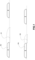
- Fig. 1 shows at the top the stopping distance D1 determined by the trackside signaling system, TS, and the at least one on-board vehicle signaling system, OB, in the light of said predetermined parameters, and at the bottom the actual stopping distance D2 of the railway vehicle RV in the absence of faults.
- a safe deceleration A safe is based on the safe deceleration of the emergency brake A brakesafe and on the deceleration of the gradient A gradient for locations with normal adhesion conditions.
- a safe v d MIN A Brake safe v d , A MAXREDADH + A gradient d
- a BRAKEsafe is the deceleration that the railway vehicle is able to achieve as a function of speed and distance.
- the equation shows that it depends on A brake emergency as a function of speed and distance.
- the values depend on the special type of brake that may be used during braking.
- the special type of braking device that may be used is obviously determined by the presence or absence of that special braking device, but also by the value of M TRACKCOND . In effect, this variable represents the inhibition of some type of special braking device on a portion of the track.
- the equation also depends on K wet as a function of the speed.
- the K wet coefficient is based on field tests according to EN15595 during which the performance of the WSP ("Wheel Slip Protection") system is evaluated and the extension of the braking distance is monitored. The extent of the braking distance is then converted to the K wet coefficient.
- the system is resilient at the first fault because the fault was considered by calculating the K dry for the nominal operating condition. This consideration also degrades the performance achievable under real nominal conditions (no fault).
- the braking distance always considers the degradation of the braking distance based on the low-adhesion conditions defined in EN15595.
- KR 102 088 409 B1 relates to an automatic shunting control system and a control method thereof
- WO 2020/118373 A1 relates to a system and method of monitoring transport and rail infrastructure
- US 2016/075354 A1 relates to an apparatus for warning of exceeding speed limit in railway vehicles configured to warn in advance to a driver or a supervisor lest a train exceed an operation limit speed in an automatic train operation system
- KR 101 945 971 B1 relates to a device for determining a train position
- KR 101 456 534 B1 relates to a train control and monitoring system
- WO 2005/095175 A1 relates to a method and an apparatus for managing the operation of trains so as to minimize the effects of low adhesion, however, the above-mentioned problems remain unsolved.
- the trackside signaling system, TS, and/or the on-board vehicle signaling system, OB will be able to use the received information regarding the adhesion condition to determine the performance achievable by the railway vehicle and adjust the calculation of the braking curves, and consequently the stopping distance, as a function of the actual working conditions of the railway vehicle.
- the trackside signaling system, TS, and/or the on-board vehicle signaling system, OB will be able to determine a true braking distance that will allow for a shorter braking distance than in the prior art so that vehicles may travel closer together, increasing overall line capacity.
- the trackside signaling system, TS, and/or the on-board vehicle signaling system, OB will result in a greater braking distance than the previous case to ensure safe stopping distances.
- the braking distance may be determined by taking into account the actual adhesion condition and the relative correction factor K wet to be applied when calculating the braking curve.
- the new signaling system is oriented toward movable blocks and automatic train operation (ATO).
- Movable blocks allow the vehicle's movement to be modulated according to their features and the actual presence of other railway vehicles.
- This type of signaling system may take into account the features of each vehicle.
- a braking system for at least one railway vehicle having the features defined in claims 1 and 2 and by railway signaling architecture having the features defined in claim 14.
- Preferred embodiments of the invention are defined in the dependent claims, the content of which is to be understood as an integral part of this description.
- the at least one trackside signaling system TS is arranged to determine the corrective factor to be applied to a predefined value of nominal deceleration of the at least one railway vehicle in low-adhesion conditions, k wet , depending on said information regarding the available adhesion of the at least one wheel W of the railway vehicle and rail R received.
- the at least one on-board vehicle signaling system OB is arranged to determine a correction factor to be applied to a predefined nominal deceleration value of the at least one railway vehicle in low-adhesion conditions, k wet , depending on said information regarding the available adhesion of at least one wheel W of the railway vehicle and rail R received.
- the trackside signaling system TS communicates a rail adhesion value ⁇ track to the passing railway vehicle.
- ⁇ min or ⁇ measured may be used in the braking distance calculation by modulating the factor, e.g., K wet , used in ETCS, determining the impact of braking distance extension due to low adhesion.
- K wet the factor used in ETCS
- This method allows for the rail adhesion data to be continuously updated and for a braking distance calculation based on the actual state of rail adhesion to be used, as described above in reference to the second embodiment.
- Another alternative approach would be to transmit the K wet coefficient instead of the measured adhesion, as described above in reference to the first embodiment.
- railway vehicle suppliers calculate a fault rate for each and every piece of braking equipment, i.e., each type of braking device and the other elements involved in initiating, propagating, and applying emergency braking.
- the vehicle is running and has no EP device faults.
- the probabilistic distribution of the EP brake is equal to one dirac.
- the vehicle will achieve 100% deceleration with a certainty of at least 1 ⁇ 10 -5 equivalent to EBCL level 5. In other words, the vehicle will reach deceleration with less certainty than the fault rate of 1 fault of the EP device.
- the vehicle will achieve 90% deceleration with a certainty of at least 1 ⁇ 10 - 10 , which is higher than EBCL level 9. In other words, the vehicle will reach deceleration with less certainty than the fault rate of 2 faults of the EP device.
- the certainty is higher than the fault rate of 1 EP device, we consider that 1 EP device will fail.
- Electropneumatic EP, electrodynamic ED, electromechanical EM braking devices usually include a WSP function, which adjusts the force exerted on the wheel based on the sliding defined as the difference in longitudinal speed between the wheels and the vehicle. To adjust the force, the device in which the WSP function is embedded measures the speed of the wheel and estimates the vehicle speed according to processed algorithms.
- each device bases the estimation of the speed of at least one railway vehicle on the speed of four different wheels and may also use an accelerometer or GPS to calculate the speed of the railway vehicle with at least as much accuracy as required by EN15595.
- the at least one special braking device may be at least one magnetic track brake, MTB, and/or sandbox and/or eddy current type brake.
- the control unit may be a solution with a Safety Integrity Level (SEL) ⁇ 2, e.g., according to the latest regulations in effect as of August 27, 2020.
- SEL Safety Integrity Level
- the invention further relates to a railway signaling architecture, including:
- the on-board vehicle signaling system when said braking system is arranged to provide to the on-board vehicle signaling system, OB, said information regarding factors affecting braking of the railway vehicle, the on-board vehicle signaling system, OB, may be arranged to determine a braking curve of the railway vehicle according to/as a function of said information regarding factors affecting braking of the railway vehicle.
- the braking system when special braking devices are present, when said braking system is arranged to provide said information regarding factors affecting braking of the railway vehicle to the on-board vehicle signaling system, OB, and said information regarding factors affecting braking of the railway vehicle comprises information regarding the availability for use of said at least one special braking device, the on-board vehicle signaling system, OB, may be arranged to determine the deceleration achievable by the railway vehicle based on said information regarding the availability for use of said at least one special braking device.
- said at least one on-board vehicle signaling system may be arranged to forward said information regarding factors affecting the braking of the railway vehicle to the at least one trackside signaling system (TS).
- At least one railway vehicle may be similarly applied in the case of a train comprising a plurality of railway vehicles.
Landscapes
- Engineering & Computer Science (AREA)
- Mechanical Engineering (AREA)
- Transportation (AREA)
- Regulating Braking Force (AREA)
- Electric Propulsion And Braking For Vehicles (AREA)
- Train Traffic Observation, Control, And Security (AREA)
Description
- This invention is generally in the field of management, control, and protection systems for railway traffic and related on-board vehicle signaling, ERTMS/ETCS (European Rail Traffic Management System/European Train Control System); in particular, the invention relates to a braking system for at least one railway vehicle and a railway signaling architecture.
- The performance of a railway vehicle during its operation is related to the railway infrastructure over which it is traveling and the performance of said railway vehicle.
- The railway vehicle and the railway infrastructure are connected by a signaling system, which allows control and management of the railway vehicle, ensuring safe operation.
- These days there are many types of railway vehicles with different features and the same may be said of signaling systems.
- Most new railway transit vehicles are called gamma trains and have a fixed composition, a specified number of railway vehicles, and a known set of braking devices.
- The signaling system is the bridge between the railway vehicle and the railway infrastructure and is part of both.
- Known signaling systems typically comprise at least one trackside signaling system, TS, and at least one on-board vehicle signaling system, OB.
- The on-board vehicle signaling system, OB, is comprised in the railway vehicle. The on-board vehicle signaling system, OB, communicates with the backbone of the at least one railway vehicle, receiving and sending information to various railway vehicle subsystems, and also communicates with the trackside signaling system, TS.
- The trackside signaling system, TS, is comprised in the railway infrastructure and communicates with an infrastructure network and the on-board vehicle signaling system, OB.
- The relationship between the speed of the at least one railway vehicle and the distance traveled by the at least one railway vehicle during braking is called the braking curve.
- Current and past signaling systems are mainly based on the fixed block concept, where the parameters for determining the braking curve are based on predefined parameters determined during the construction of the at least one railway vehicle or train.
- Said trackside signaling systems, TS, and on-board vehicle signaling systems, OB, are arranged to determine said braking curve. From the braking curve they may then determine the stopping distance of said railway vehicle.
- As explained above, this braking curve is determined for each railway vehicle as a function of predetermined parameters, the value of which is predefined at the time the railway vehicle is made.
- As for the case of unfavorable environmental conditions, a correction factor is usually used for cases of low adhesion coefficient. In the railway industry, this correction factor is commonly referred to as Kwet.
- In the prior art, said corrective factor Kwet is assigned a predetermined value so as to ensure that, even under adverse environmental conditions, the determined stopping distance is sufficient to ensure that safety is maintained. Consequently, the value of this corrective factor Kwet is usually defined considering that there is a low-adhesion condition.
- As explained above, signaling systems are mainly based on the fixed block concept, where the parameters for determining the braking curve are based on predefined parameters determined during the construction of at least one railway vehicle or train. Therefore, also the value of this correction factor Kwet is only defined during the construction of the at least one railway vehicle or train.
- As a result, during the normal operating condition of the railway vehicle, even when the railway vehicle is not in favorable environmental conditions, the braking curve determined by the at least one trackside signaling system, TS, and the at least one on-board vehicle signaling system, OB, will be a non-real degraded braking curve, which would account for the presence of said alleged unfavorable environmental conditions, which are not actually present.
- As a result, the trackside signaling system, TS, and the at least one on-board vehicle signaling system, OB, would assign a greater stopping distance to said railway vehicle than the railway vehicle could actually achieve under more favorable environmental conditions.
- On the other hand, with regard to the case wherein there is at least one fault at the level of the railway vehicle, in addition to the correction factor Kwet, for the determination of the braking curve by the at least one trackside signaling system, TS, and the at least one on-board vehicle signaling system, OB, further predetermined parameters may also be used, the value of which is again predefined at the time the railway vehicle is made.
- In such a case, the braking curve determined by the at least one trackside signaling system, TS, and the at least one on-board vehicle signaling system, OB, will be a further degraded braking curve, which would also take into account the possible presence of said at least one fault.
- As a result, even when the railway vehicle has no fault, the braking curve determined by the at least one trackside signaling system, TS, and the at least one on-board vehicle signaling system, OB, will be a non-real degraded braking curve that takes into account the presence of said presumed fault.
- In this case, the trackside signaling system, TS, and the at least one on-board vehicle signaling system, OB, would therefore assign a greater stopping distance to said railway vehicle than the railway vehicle could actually achieve in the absence of faults or favorable environmental conditions.
-
Fig. 1 shows at the top the stopping distance D1 determined by the trackside signaling system, TS, and the at least one on-board vehicle signaling system, OB, in the light of said predetermined parameters, and at the bottom the actual stopping distance D2 of the railway vehicle RV in the absence of faults. - The determination of a degraded braking curve and the consequent allocation of a longer stopping distance to said railway vehicle result in a disadvantageous handling of e.g., traffic on the rail line. In effect, the railway vehicles will be made to travel greater distances from each other than are necessary.
- A possible example of a braking curve calculation is provided generically below. The calculation of the braking curve is for example described in the ETCS specification (ERTMS/ETCS, Subset 026-3, Subset 026-7).
- A braking curve is usually generated by the braking calculation performed by the on-board vehicle signaling system OB. The calculation of the braking curve is based in part on said correction factor Kwet in case of a low adhesion coefficient. This correction factor usually depends on the speed Kwet(V) and said vehicle.
- Some examples of parameters that may impact the calculation of the braking curve are for example:
- safe deceleration, relevant to safety: A_SAFE (V, d): Depends on speed and distance, dependent on the railway vehicle;
- safe deceleration of the emergency brake: A_BRAKE_SAFE (V, d): Depends on the speed and distance, depends on the vehicle;
- emergency brake deceleration: A_BRAKE_EMERGENCY (V, d): Depends on the speed and distance, depends on the vehicle;
- coefficients of the confidence levels: M_NVEBCL: National value, dependent on the railway line;
- vehicle braking performance: Kdry(V, M_NVEBCL): Depends on the speed and confidence level, depends on the vehicle;
- weighing factor for available wheel/rail adhesion: M_NVAVADH: National value, dependent on the rail line;
- adhesion factor: M_ADHESION: Coefficient on the rail, dependent on the rail;
- condition type of the rail: M_TRACKCOND: may disable certain types of brakes, depending on the rail;
- special brakes (EP, MTB, Eddy current, ED): Used to affect brake build-up and deceleration time, depending on the railway vehicle;
- maximum deceleration under reduced adhesion conditions (mu <0.06): A_MAXREDADH: According to the location of the brake and special brakes, national value.
- In the prior art, the emergency brake deceleration and the coefficients Kdry and Kwet that affect the overall braking distance calculation and the overall performance of the railway vehicle are measured during commissioning or calculated offline using Monte Carlo simulations.
- The formula that may be used is

- The safe deceleration Asafe is based on the safe deceleration of the emergency brake Abrakesafe and on the deceleration of the gradient Agradient for locations with normal adhesion conditions.

- The safe deceleration Asafe is based on the minimum value between the safe emergency brake deceleration Abrakesafe and the maximum deceleration in reduced adhesion conditions AMAXREDADH and deceleration of the gradient Agradient for positions with reduced adhesion conditions.

- ABRAKEsafe is the deceleration that the railway vehicle is able to achieve as a function of speed and distance. The equation shows that it depends on Abrake emergency as a function of speed and distance. The values depend on the special type of brake that may be used during braking.
- The special type of braking device that may be used is obviously determined by the presence or absence of that special braking device, but also by the value of MTRACKCOND. In effect, this variable represents the inhibition of some type of special braking device on a portion of the track.
- The equation also depends on Kdry as a function of speed and confidence level. The confidence level is the target for the reliability of the Kdry coefficient. It is used to account for the fault rate of a piece of equipment and the distribution around the expected value.
- The equation also depends on Kwet as a function of the speed. The Kwet coefficient is based on field tests according to EN15595 during which the performance of the WSP ("Wheel Slip Protection") system is evaluated and the extension of the braking distance is monitored. The extent of the braking distance is then converted to the Kwet coefficient.
- The equation also depends on MNVAVADH and this value is used to allow modulation of the Kwet coefficient by the operator.
- The formulas above are just an example of the various possible formulas for calculating the overall braking distance.
- The following are some exemplifying cases:
- The following data provides an example of the use of the different variables and their impact (based on actual field data):
- MNVAVADH = 0 | Kwet is fully considered in the formula (3) above;
- Kwet = 0.7 | Kwet is determined according to EN15595;
- MADHESION = 1 | The rail is not slippery;
- Kdry = 0.8 | Kdry calculated based on the EBCL level, considers 1 fault;
- AMAXREDADH = 0.5 | Not relevant in this situation since the rail is not slippery;
- With the variables set as described above, the system is resilient at the first fault because the fault was considered by calculating the Kdry for the nominal operating condition. This consideration also degrades the performance achievable under real nominal conditions (no fault).
- With the variables set as described above, the system should run at a slower speed from the second fault, thus affecting operational service.
- With the variables set as above, under normal dry running conditions, the braking distance always considers the degradation of the braking distance based on the low-adhesion conditions defined in EN15595.
- Considering now this second dataset:
- MNVAVADH = 0 | Kwet is fully considered in the formula (3) above;
- Kwet = 0.7 | Kwet is determined according to EN15595;
- MADHESION = 0 | the rail is slippery;
- Kdry = 0.8 | Kdry calculated based on the EBCL level, considers 1 fault;
- AMAXREDADH = 0.3 | relevant in this situation since the rail is slippery;
- With the variables set as described above, the rail is slippery and the minimum value between the safe emergency brake deceleration and AMAXREDADH is used to determine the safe deceleration.
- Considering that A_MAXREDADH is the minimum, Kdry and Kwet are no longer used, and the deceleration used does not depend on either actual adhesion or equipment fault.
-
KR 102 088 409 B1WO 2020/118373 A1 relates to a system and method of monitoring transport and rail infrastructure,US 2016/075354 A1 relates to an apparatus for warning of exceeding speed limit in railway vehicles configured to warn in advance to a driver or a supervisor lest a train exceed an operation limit speed in an automatic train operation system,KR 101 945 971 B1 KR 101 456 534 B1 WO 2005/095175 A1 relates to a method and an apparatus for managing the operation of trains so as to minimize the effects of low adhesion, however, the above-mentioned problems remain unsolved. - One object of this invention is to provide a solution for informing a trackside signaling system, TS, and/or an on-board vehicle signaling system, OB, on the actual performance achievable by the vehicle during braking, in real time, depending on the actual adhesion condition of the line on which the at least one railway vehicle is traveling.
- In this way, the trackside signaling system, TS, and/or the on-board vehicle signaling system, OB, will be able to use the received information regarding the adhesion condition to determine the performance achievable by the railway vehicle and adjust the calculation of the braking curves, and consequently the stopping distance, as a function of the actual working conditions of the railway vehicle.
- For example, under dry conditions, the trackside signaling system, TS, and/or the on-board vehicle signaling system, OB, will be able to determine a true braking distance that will allow for a shorter braking distance than in the prior art so that vehicles may travel closer together, increasing overall line capacity.
- Conversely, in low-adhesion conditions, the trackside signaling system, TS, and/or the on-board vehicle signaling system, OB, will result in a greater braking distance than the previous case to ensure safe stopping distances. In this case, the braking distance may be determined by taking into account the actual adhesion condition and the relative correction factor Kwet to be applied when calculating the braking curve.
- The new signaling system is oriented toward movable blocks and automatic train operation (ATO).
- Movable blocks allow the vehicle's movement to be modulated according to their features and the actual presence of other railway vehicles. This type of signaling system may take into account the features of each vehicle.
- The aforesaid and other objects and advantages are achieved, according to one aspect of the invention, by a braking system for at least one railway vehicle having the features defined in claims 1 and 2 and by railway signaling architecture having the features defined in claim 14. Preferred embodiments of the invention are defined in the dependent claims, the content of which is to be understood as an integral part of this description.
- The functional and structural features of some preferred embodiments of a braking system for a vehicle for at least one railway vehicle and a railway signaling architecture according to the invention will now be described. Reference is made to the appended drawings, wherein:
-
Fig. 1 illustrates by way of example two possible braking curves; -
Fig. 2 illustrates an embodiment of the invention; -
Fig. 2B illustrates a block diagram of an example of using adhesion information; -
Fig. 3 illustrates three possible usage configurations; -
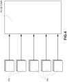
Fig. 4 illustrates an embodiment in which information regarding factors affecting the braking of the railway vehicle is transmitted in a distributed manner; and -
Fig. 5 illustrates an embodiment in which information regarding factors affecting the braking of the railway vehicle is transmitted centrally. - Before describing a plurality of embodiments of the invention in detail, it should be clarified that the invention is not limited in its application to the construction details and configuration of the components presented in the following description or illustrated in the drawings. The invention may assume other embodiments and be implemented or constructed in practice in different ways. It should also be understood that the phraseology and terminology have a descriptive purpose and should not be construed as limiting. The use of "include" and "comprise" and their variations is to be understood as encompassing the elements set out below and their equivalents, as well as additional elements and the equivalents thereof.
- In the following, a first embodiment of a braking system for at least one railway vehicle according to the invention is described.
- In this first embodiment, the braking system is arranged to provide information regarding respective factors affecting braking of the railway vehicle to at least one trackside signaling system, TS, or to at least one on-board vehicle signaling system, OB, or to both at least one trackside signaling system, TS, and at least one on-board vehicle signaling system, OB. Such information regarding respective factors affecting the railway vehicle braking includes information regarding a correction factor to be applied to a predefined value of nominal deceleration of the at least one railway vehicle in low-adhesion conditions, kwet.
- This information regarding respective factors affecting railway vehicle braking is determined in real time by the braking system. In particular, such information regarding factors affecting railway vehicle braking is not static and is not default values defined during the construction of the railway vehicle.
- For example, the braking system may determine in real time the corrective factor to be applied to a predefined nominal deceleration value of the at least one railway vehicle in low-adhesion conditions, kwet, from, for example, an adhesion value associated with an axle of said railway vehicle. For example, it may be the same braking system that determines the corrective factor kwet by measuring the adhesion value of said one axle or by reading or receiving the adhesion value of said one axle from a special system/means/device associated with said braking system (e.g., a "wheel slide protection" system, WSP).
- In a second embodiment, the
braking system 100 is again arranged to provide information regarding respective factors affecting braking of the railway vehicle to at least one trackside signaling system TS, or to at least one on-board vehicle signaling system OB, or to both at least one trackside signaling system TS and at least one on-board vehicle signaling system OB. - In contrast to the preceding embodiment, in this second embodiment, the information regarding respective factors affecting braking of the railway vehicle includes information regarding the available adhesion of at least one wheel W of the railway vehicle and rail R.
- The information regarding respective factors affecting the braking of the railway vehicle is again determined in real time by the braking system.
- In this embodiment, the at least one trackside signaling system TS is arranged to determine the corrective factor to be applied to a predefined value of nominal deceleration of the at least one railway vehicle in low-adhesion conditions, kwet, depending on said information regarding the available adhesion of the at least one wheel W of the railway vehicle and rail R received. Additionally or alternatively, the at least one on-board vehicle signaling system OB is arranged to determine a correction factor to be applied to a predefined nominal deceleration value of the at least one railway vehicle in low-adhesion conditions, kwet, depending on said information regarding the available adhesion of at least one wheel W of the railway vehicle and rail R received.
- Preferably, as for example observable in
Fig. 2 , a braking system for at least one railway vehicle may include at least onebraking device 102. - Preferably, for any of the preceding described embodiments, the information regarding respective factors affecting braking of the railway vehicle may further include at least one of:
- information regarding an optimal sliding point between wheel and rail, determined by the
braking system 100; - information regarding a speed of at least one railway vehicle;
- information regarding a braking distance determined by the braking system (100) based on the current speed of the at least one railway vehicle;
- information regarding the availability for use of said at least one
braking device 102; - information regarding a deceleration of the railway vehicle;
- information regarding a level of braking force applied by at least one braking device.
- The term "providing" to at least one trackside signaling system, TS, or to at least one on-board vehicle signaling system, OB, or to both the at least one trackside signaling system, TS, in this invention, means both where there is a direct provision and where there is an indirect provision obtained through an intermediate provision to one or more intermediate means elements/devices or systems, e.g., an intermediate train control and management system, TCMS ("TRAIN CONTROL & MANAGEMENT SYSTEM") TCMS that receives information from the braking system and transmits it to the at least one trackside signaling system, TS, or the at least one on-board vehicle signaling system, OB, or to both the at least one trackside signaling system, TS, and the at least one on-board vehicle signaling system, OB.
- Factors affecting the railway vehicle braking may be understood to mean all those aspects internal to the railway vehicle or environmental aspects external to the railway vehicle that may impact the braking action of the railway vehicle.
- Information regarding the available adhesion of at least one wheel of the railway vehicle and rail may be understood as information indicative of the currently available adhesion of at least one wheel of the railway vehicle and rail, for example detected or determined in real time according to known algorithms.
- Information regarding an optimal sliding point between wheel and rail, determined by the braking system, may be understood as information indicative of an optimal sliding point between wheel and rail, for example detected or determined in real time according to known algorithms. Modern WSPs use the axle sliding point to improve braking performance in low-adhesion conditions. This sliding point may be determined in several ways. Many of them require trial and error to determine the optimal sliding point. This generates a loss of braking force compared to having the optimal sliding point already available. The optimum sliding point is valuable information for the braking system because it may affect the overall deceleration/braking distance of the vehicle.
- Using a principle similar to that described for adhesion information, the optimal sliding point may be shared between related braking devices and related signaling devices and then sent back to a subsequent railway vehicle or train.
- Information regarding a correction factor to be applied to a predefined value of nominal deceleration of at least one railway vehicle in low-adhesion conditions, kwet, may be understood as information indicative of a correction factor value in the case of a low adhesion coefficient.
- Information regarding a railway vehicle speed may be understood as information indicative of a current railway vehicle speed detected or determined in real time.
- Information regarding a braking distance determined by the braking system from the current speed of the vehicle may be understood as information indicative of the braking distance determined by the braking system, according to any known algorithm.
- Information regarding the current availability for use of said at least one braking device may be understood to mean, for example, information regarding whether a certain braking device is usable or not, for example due to a fault.
- Information regarding a current deceleration of the railway vehicle may be understood as information indicating the deceleration of the railway vehicle in real time.
- Information regarding a current braking force level may be understood as information indicative of the current level of braking applied by the braking devices. This information is, for example, the percentage of application with respect to a maximum possible braking level. This information may also be sent for monitoring purposes.
- This information may be used to adapt the braking distance calculation based on the actual force transferred rather than the expected force to be transferred. This would make the braking distance calculation more accurate.
- Preferably, the at least one braking device is of the electropneumatic or electrodynamic or electromechanical type.
- The following is an example of using adhesion information. In this case, it is considered that the at least one braking device may measure the adhesion present between the wheel and rail. A common method for measuring adhesion is described in EN15595. The measured adhesion value may then be communicated by the braking system. As may be observed in
Fig. 2B , the braking distance calculation uses as input an adhesion value µmin based on the lowest value between the measured adhesion µmeasured and the rail adhesion µtrack to determine the braking distance, MIN(µmeasured, µtrack). - Vaxle1,2,..n is the speed of the respective axles used to determine the measured adhesion µmeasured.
- The trackside signaling system TS communicates a rail adhesion value µtrack to the passing railway vehicle.
- When the first railway vehicle brakes, the measured adhesion µmeasured is communicated to the on-board vehicle signaling system OB. At the end of each braking sequence (end of braking or with railway vehicle speed is equal to 0 VRV =0) the measured adhesion of the on-board vehicle signaling system µOBmeasured is communicated to the trackside signaling system TS. The trackside signaling system TS stores the rail information received pOBmeasured. The on-board vehicle signaling system OB of a subsequent railway vehicle may receive a µtrack rail adhesion value µtrack updated based on said µOBmeasured.
- µtrack is the average adhesion measured over at least the last 3 stored adhesion values, AVERAGE(µ, µn-1, µn-2).
- µmin or µmeasured may be used in the braking distance calculation by modulating the factor, e.g., Kwet, used in ETCS, determining the impact of braking distance extension due to low adhesion.
- In this case

- This would allow the braking curves to be modulated based on the actual measured adhesion values and to have a conservative approach since the coefficient thus defined would estimate a longer braking distance than the actual vehicle performance due to the rail cleaning effect.
- This method allows for the rail adhesion data to be continuously updated and for a braking distance calculation based on the actual state of rail adhesion to be used, as described above in reference to the second embodiment. Another alternative approach would be to transmit the Kwet coefficient instead of the measured adhesion, as described above in reference to the first embodiment.
- The following is an example of using information regarding the availability of the braking device.
- Currently, railway vehicle suppliers calculate a fault rate for each and every piece of braking equipment, i.e., each type of braking device and the other elements involved in initiating, propagating, and applying emergency braking.
- In the current ETCS braking distance calculation, a confidence level variable is used to determine the validity of emergency braking deceleration, taking into account the possible unavailability of the braking devices and the probabilistic distribution of their force. Typically, an offline Monte Carlo approach is used for the faults of different devices.
- Disadvantageously, this approach is static and does not consider actual faults but does take into account the broader probability of faults.
- Due to this invention, the signaling, given the appropriate information, may comprise in real time the availability of all braking devices on board the vehicle. With this information exactly how much braking distance is achievable may be calculated.
- For example, the railway vehicle has only electropneumatic brakes EP, no other components are part of the initiation, propagation, or application of emergency braking. Consider, for example, that 10 devices are used nominally. Each device corresponds to 10% of the entire braking force. The fault rate of the single EP braking device is 5×10⁻⁶ per hour.
- The vehicle is running and has no EP device faults. The probabilistic distribution of the EP brake is equal to one dirac. The vehicle will achieve 100% deceleration with a certainty of at least 1×10⁻⁵ equivalent to EBCL level 5. In other words, the vehicle will reach deceleration with less certainty than the fault rate of 1 fault of the EP device. The vehicle will achieve 90% deceleration with a certainty of at least 1 ×10- 10, which is higher than EBCL level 9. In other words, the vehicle will reach deceleration with less certainty than the fault rate of 2 faults of the EP device. However, since the certainty is higher than the fault rate of 1 EP device, we consider that 1 EP device will fail.
- The vehicle is running and has 1 EP device fault. This has been notified to the on-board vehicle signaling, meaning that the deceleration degraded with 1 EP device fault is 90% of the nominal deceleration. The vehicle will achieve 90% deceleration with a certainty of at least 1×10⁻⁵ equivalent to EBCL level 5. The vehicle will achieve degraded deceleration with less certainty than the fault rate of 1 fault of the EP device. It achieves degraded deceleration and not the nominal deceleration because 1 EP unit has already failed. The vehicle will achieve 80% deceleration with a certainty of at least 1×10⁻¹⁰ above EBCL level 9. The vehicle will reach deceleration with less certainty with respect to the fault of 2 faults of the EP device.
- The following steps show how to calculate the deceleration based on the required EBCL and based on the fault rates of the considered device.

- This example was provided for a vehicle using only EP electropneumatic brakes. The same concept may be applied to a vehicle with multiple types of braking devices if they all contribute to deceleration. The above may be applied similarly to special braking devices.
- In a further aspect, referring to the current deceleration and speed of the vehicle, these may be provided by the braking devices to the related signaling devices TS, OB. The multitude of measurements may then be analyzed, and a more accurate railway vehicle speed and deceleration are made available.
- Generally, the on-board vehicle signaling system OB bases the calculation of the reference speed on a limited number of speed sensors, typically between 1 and 2.
- Electropneumatic EP, electrodynamic ED, electromechanical EM braking devices usually include a WSP function, which adjusts the force exerted on the wheel based on the sliding defined as the difference in longitudinal speed between the wheels and the vehicle. To adjust the force, the device in which the WSP function is embedded measures the speed of the wheel and estimates the vehicle speed according to processed algorithms.
- Locally, each device bases the estimation of the speed of at least one railway vehicle on the speed of four different wheels and may also use an accelerometer or GPS to calculate the speed of the railway vehicle with at least as much accuracy as required by EN15595.
- Based on the number of wheels considered and compliance with the EN standard, the estimation of the vehicle speed by the brake devices will be better than that calculated by the on-board vehicle signaling system OB.
- In addition, the calculation of the speed of different units could be concentrated to have a more accurate estimate of the speed of the at least one railway vehicle.
- In a further aspect, obviously the
braking system 100 may also controlmultiple braking devices 102, associated with, for example, respective wheels of an axle or various axles. - Preferably, the braking system may also comprise at least one special braking device ("special brake"). In this case, the information regarding factors affecting the braking of the railway vehicle may further comprise:
- information regarding the current availability for use of said at least one special braking device;
- information regarding a current level of braking force applied by at least one special braking device.
- Information regarding the current availability for use of said at least one special braking device may be understood as, for example, information indicating whether a certain special braking device is usable or not, for example due to a fault.
- Information regarding a current level of braking force applied by at least one special braking device may be understood as, for example, information indicative of the current level of braking applied by special braking devices. This information is, for example, the percentage of application with respect to a maximum possible braking level. This information may also be sent for monitoring purposes.
- Preferably, the at least one special braking device may be at least one magnetic track brake, MTB, and/or sandbox and/or eddy current type brake.
- For example, the sandbox belongs to the category of special brakes; although it has the peculiarity of not directly contributing to the deceleration of the vehicle, it enhances the force generated by the other braking devices, and therefore has an impact on the braking of the railway vehicle.
- The sandbox efficiency information may also be sent for monitoring purposes.
- As observable in
Fig. 3 , in the configuration 1 of a railway signaling architecture, the braking system may provide at least one of said information regarding factors affecting braking of the railway vehicle directly to the at least one trackside signaling system, TS. - In the configuration 2 of a railway signaling architecture, the braking system may provide at least one of said information regarding factors affecting braking of the railway vehicle to the at least one on-board vehicle signaling system, OB. In this case, said at least one on-board vehicle signaling system, OB, may be arranged to forward said information regarding factors affecting braking of the railway vehicle to the at least one trackside signaling system, TS.
- In the configuration 3 of a railway signaling architecture, the braking system may be arranged to provide at least one of said information regarding factors affecting braking of the railway vehicle also by sending said information regarding factors affecting braking of the railway vehicle also to at least one train control and management system, TCMS, of said at least one railway vehicle. In such a case, said at least one on-board vehicle signaling system, OB, and/or said at least one trackside signaling system, TS, may each be arranged to receive said information concerning factors affecting braking of the railway vehicle from said train control and management system, TCMS.
- In a further embodiment, when the braking system is arranged to provide at least one of said information regarding factors affecting braking of the railway vehicle to the at least one trackside signaling system, TS, the braking system may be arranged to transmit at least one of said information regarding factors affecting braking of the railway vehicle also to at least one remote server. In this case, the trackside signaling system, TS, may be arranged to receive said information regarding factors affecting braking of the railway vehicle from said at least one remote server.
- As is observable in
Fig. 4 , said at least one braking device may be arranged to directly provide said information regarding factors affecting braking of the railway vehicle to said at least one on-board vehicle signaling system, OB, and/or said at least one trackside signaling system, TS, or again to said at least one train control and management system, TCMS. When present, said at least onespecial braking device 104 may also be arranged to provide said information regarding factors affecting braking of the railway vehicle to said at least one on-board vehicle signaling system, OB, and/or said at least one trackside signaling system, TS. - That is, the information is provided in a distributed manner by the one or more braking devices or one or more special braking devices.
- As observable in
Fig. 5 , in a further embodiment, the braking system may comprise at least onebraking control unit 106, for example assigned to control the one or more braking devices and/or the one or more special braking devices. In this case, the braking control unit may be arranged to collect centrally from the braking devices said information regarding factors affecting braking of the railway vehicle to be provided to said at least one on-board vehicle signaling system, OB, and/or said at least one trackside signaling system, TS, or said at least one train control and management system, TCMS. When the special braking devices are present, the braking control unit may be arranged to collect also centrally from the special braking devices said information concerning factors affecting braking of the railway vehicle to be provided to said at least one on-board vehicle signaling system, OB, and/or said at least one trackside signaling system, TS. - For some types of architectures, such as the centralized one described above, it is possible to perform the braking distance calculation through the main braking device.
- In effect, the real-time data needed to make an accurate estimate of braking distance is available to the unit.
- Preferably, said braking control unit may process at least one of said information on factors affecting braking of the railway vehicle.
- The control unit may be a solution with a Safety Integrity Level (SEL) ≥ 2, e.g., according to the latest regulations in effect as of August 27, 2020.
- Preferably, the braking system provides to the at least one trackside signaling system, TS, or to the at least one on-board vehicle signaling system, OB, or to both the at least one trackside signaling system, TS, and the at least one on-board vehicle signaling system, OB, said information regarding factors affecting braking of the railway vehicle via at least one wired communication means or one wireless communication means. For example, the communication means may be a Digital I/O, Ethernet, MVB, CAN, Echelon, Bluetooth, WiFi, GSM.
- The invention further relates to a railway signaling architecture, including:
- a braking system according to any of the embodiments described above;
- at least one trackside signaling system, TS, or at least one on-board vehicle signaling system, OB, or both at least one trackside signaling system, TS, and at least one on-board vehicle signaling system, OB.
- In said railway signaling management architecture, when said braking system is arranged to provide to the on-board vehicle signaling system, OB, said information regarding factors affecting braking of the railway vehicle, the on-board vehicle signaling system, OB, may be arranged to determine a braking curve of the railway vehicle according to/as a function of said information regarding factors affecting braking of the railway vehicle.
- Further, when said braking system is arranged to provide said information regarding factors affecting braking of the railway vehicle to the on-board vehicle signaling system, OB, and said information regarding factors affecting braking of the railway vehicle comprise information regarding the availability for use of said at least one braking device, the on-board vehicle signaling system, OB, may be arranged to determine the deceleration achievable by the railway vehicle based on said information regarding the availability for use of said at least one braking device.
- Moreover, when special braking devices are present, when said braking system is arranged to provide said information regarding factors affecting braking of the railway vehicle to the on-board vehicle signaling system, OB, and said information regarding factors affecting braking of the railway vehicle comprises information regarding the availability for use of said at least one special braking device, the on-board vehicle signaling system, OB, may be arranged to determine the deceleration achievable by the railway vehicle based on said information regarding the availability for use of said at least one special braking device.
- Preferably, when the braking system is arranged to provide at least one of said information regarding factors affecting the braking of the railway vehicle to the at least one on-board vehicle signaling system (OB), said at least one on-board vehicle signaling system (OB) may be arranged to forward said information regarding factors affecting the braking of the railway vehicle to the at least one trackside signaling system (TS).
- Preferably, said braking system may be arranged to provide at least one of said information regarding factors affecting the braking of the railway vehicle by sending said information regarding factors affecting the braking of the railway vehicle to at least one train control and management system (TCMS) of said at least one railway vehicle. Further, said at least one on-board vehicle signaling system (OB) and/or said at least one trackside signaling system (TS) may be arranged to receive said information regarding factors affecting the braking of the railway vehicle from said train control and management system (TCMS).
- Preferably, when the braking system is arranged to provide at least one of said information regarding factors affecting the braking of the railway vehicle to the at least one trackside signaling system (TS), said braking system may be arranged to transmit at least one of said information regarding factors affecting the braking of the railway vehicle to at least one remote server, and said trackside signaling system (TS) may be arranged to receive said information regarding factors affecting the braking of the railway vehicle from said at least one remote server.
- That which is explained in this description with respect to at least one railway vehicle may be similarly applied in the case of a train comprising a plurality of railway vehicles.
- The advantage achieved is therefore that of having proposed a solution that allows the trackside signaling system TS and the on-board vehicle signaling system to determine the braking curve of the railway vehicle and the stopping distance of the railway vehicle as a function of real time parameters inherent to the adhesion condition surrounding it. Various aspects and embodiments of a braking system with a signaling architecture according to the invention have been described. Furthermore, the invention is not limited to the described embodiments, but may be varied within the scope defined by the appended claims.
Claims (15)
- Braking system (100) for at least one railway vehicle (RV), wherein said braking system (100) is arranged to provide to at least one trackside signaling system (TS), or to at least one on-board vehicle signaling system (OB), or to both at least one trackside signaling system (TS) and at least one on-board vehicle signaling system (OB), information regarding respective factors affecting braking of the railway vehicle;wherein said information regarding respective factors affecting the braking of the railway vehicle includes:- information regarding a correction factor to be applied to a predefined nominal deceleration value of the at least one railway vehicle in conditions of low adhesion, kwet;wherein said information regarding factors affecting the braking of the railway vehicle is determined in real time by said braking system.
- Braking system (100) for at least one railway vehicle (RV), wherein said braking system (100) is arranged to provide to at least one trackside signaling system (TS), or to at least one on-board vehicle signaling system (OB), or to both at least one trackside signaling system (TS) and at least one on-board vehicle signaling system (OB), information regarding respective factors affecting the braking of the railway vehicle;wherein said information regarding respective factors affecting the braking of the railway vehicle includes:- information regarding the available adhesion of at least one wheel (W) of the railway vehicle and rail (R);wherein said information regarding respective factors affecting the braking of the railway vehicle is determined in real time by said braking system;wherein said at least one trackside signaling system (TS) is arranged to determine a corrective factor to be applied to a predefined nominal deceleration value of the at least one railway vehicle in low-adhesion conditions, kwet, as a function of said information regarding the available adhesion of the at least one wheel (W) of the railway vehicle and rail (R) received, and/or said at least one on-board vehicle signaling system (OB) is arranged to determine a corrective factor to be applied to a predetermined nominal deceleration value of the at least one railway vehicle in low-adhesion conditions, kwet, as a function of said information regarding the available adhesion of the at least one wheel (W) of the railway vehicle and rail (R) received.
- Braking system according to claim 1 or 2, wherein said braking system includes at least one braking device (102).
- Braking system according to any of the preceding claims, wherein said information regarding respective factors affecting braking of the railway vehicle further includes at least one of:- information regarding an optimal sliding point between wheel and rail, determined by the braking system (100);- information regarding a speed of the at least one railway vehicle;- information regarding a braking distance determined by the braking system (100) based on the current speed of the at least one railway vehicle;- information regarding the availability for use of the at least one braking device (102);- information regarding a deceleration of the railway vehicle;- information regarding a level of braking force applied by the at least one braking device.
- Braking system according to any of claims 3 or 4, wherein said at least one braking device is of an electropneumatic or electrodynamic or electromechanical type.
- Braking system according to any of the preceding claims, further comprising at least one special braking device (104);
wherein said information regarding factors affecting braking of the railway vehicle, determined in real time by said braking system, further comprises:- information regarding the availability for use of said at least one special braking device (104);- information regarding a level of braking force applied by the at least one special braking device (104). - Braking system according to claim 6, wherein said at least one special braking device includes at least one of the following devices:- a magnetic track brake, MTB;- a sandbox;- an Eddy current brake.
- Braking system according to any of claims 3 to 7, wherein said at least one braking device is arranged to provide said information regarding factors affecting the braking of the railway vehicle to said at least one on-board vehicle signaling system (OB) and/or said at least one trackside signaling system (TS).
- Braking system according to any of claims 6 to 8, wherein said at least one special braking device is arranged to provide said information regarding factors affecting the braking of the railway vehicle to said at least one on-board vehicle signaling system (OB) and/or said at least one trackside signaling system (TS).
- Braking system according to any of the preceding claims from 3 to 9, comprising at least one braking control unit;
the braking control unit being arranged to collect in a centralized manner from the braking devices said information regarding factors affecting the braking of the railway vehicle to be provided to said at least one on-board vehicle signaling system (OB) and/or said at least one trackside signaling system (TS). - Braking system according to claim 10, when dependent on claim 6, wherein the braking control unit is arranged to collect in a centralized way from the special braking devices said information regarding factors affecting the braking of the railway vehicle to be provided to said at least one on-board vehicle signaling system (OB) and/or said at least one trackside signaling system (TS).
- Braking system according to claim 10 or 11, wherein said braking control unit is arranged to process at least one of said information regarding factors affecting the braking of the railway vehicle.
- Braking system according to any of the preceding claims, wherein the braking system provides to the at least one trackside signaling system (TS), or to the at least one on-board vehicle signaling system (OB) or to both the at least one trackside signaling system (TS) and at least one on-board vehicle signaling system (OB), said information regarding factors affecting the braking of the railway vehicle through at least one hard-wired communication means or wireless communication means.
- Railway signaling architecture, including:- a braking system according to any of the preceding claims;- at least one trackside signaling system (TS), or at least one on-board vehicle signaling system (OB), or at least one trackside signaling system (TS) and at least one on-board vehicle signaling system (OB).
- Railway signaling architecture, according to claim 14, wherein:- when said braking system is arranged to provide to the on-board vehicle signaling system (OB) said information regarding factors affecting the braking of the railway vehicle, the on-board vehicle signaling system (OB) is arranged to determine a braking curve of the railway vehicle as a function of said information regarding factors affecting the braking of the railway vehicle.
Applications Claiming Priority (2)
| Application Number | Priority Date | Filing Date | Title |
|---|---|---|---|
| IT202000020677 | 2020-08-31 | ||
| PCT/IB2021/057936 WO2022043964A1 (en) | 2020-08-31 | 2021-08-31 | Braking system for at least one railway vehicle and railway signaling architecture |
Publications (2)
| Publication Number | Publication Date |
|---|---|
| EP4204265A1 EP4204265A1 (en) | 2023-07-05 |
| EP4204265B1 true EP4204265B1 (en) | 2024-07-10 |
Family
ID=73139267
Family Applications (1)
| Application Number | Title | Priority Date | Filing Date |
|---|---|---|---|
| EP21778218.4A Active EP4204265B1 (en) | 2020-08-31 | 2021-08-31 | Braking system for at least one railway vehicle and railway signaling architecture |
Country Status (9)
| Country | Link |
|---|---|
| US (1) | US20240262401A1 (en) |
| EP (1) | EP4204265B1 (en) |
| JP (1) | JP7817246B2 (en) |
| KR (1) | KR20230088676A (en) |
| CN (1) | CN115867477B (en) |
| BR (1) | BR112023002653A2 (en) |
| ES (1) | ES2987302T3 (en) |
| HU (1) | HUE067751T2 (en) |
| WO (1) | WO2022043964A1 (en) |
Family Cites Families (11)
| Publication number | Priority date | Publication date | Assignee | Title |
|---|---|---|---|---|
| EP1730009A1 (en) * | 2004-03-27 | 2006-12-13 | DeltaRail Group Limited | Train operating system |
| DE102004017632A1 (en) * | 2004-04-10 | 2005-10-27 | Daimlerchrysler Ag | Method for determining brake characteristics and brake control |
| DE102011113117A1 (en) * | 2011-09-09 | 2013-03-14 | Knorr-Bremse Systeme für Schienenfahrzeuge GmbH | Brake control device for rail vehicles, brake system for rail vehicles and methods for brake control for rail vehicles and computer program product |
| KR101456534B1 (en) * | 2013-06-17 | 2014-10-31 | 현대로템 주식회사 | Train control supervision system |
| KR101866610B1 (en) | 2014-09-17 | 2018-06-11 | 엘에스산전 주식회사 | Apparatus for Warning of Exceeding Speed Limit in Railway Vehicles |
| IT201700100433A1 (en) * | 2017-09-07 | 2019-03-07 | Faiveley Transport Italia Spa | Control procedure of a braking system of at least one railway vehicle. |
| KR102088409B1 (en) | 2017-12-07 | 2020-03-13 | 한국철도기술연구원 | Automatic shunting control system and method thereof |
| WO2019187643A1 (en) | 2018-03-27 | 2019-10-03 | 株式会社日立製作所 | Train control system and train control method |
| KR101945971B1 (en) | 2018-04-26 | 2019-05-02 | (주)그린시스템 | Method and apparatus for determining train location |
| AU2019396832B2 (en) * | 2018-12-13 | 2021-07-29 | Asiatic Innovations Pty Ltd | Transport and rail infrastructure monitoring system |
| CN110949342B (en) * | 2019-12-17 | 2021-06-04 | 中车株洲电力机车有限公司 | Air braking parking control method and system for railway vehicle |
-
2021
- 2021-08-31 EP EP21778218.4A patent/EP4204265B1/en active Active
- 2021-08-31 HU HUE21778218A patent/HUE067751T2/en unknown
- 2021-08-31 KR KR1020237006529A patent/KR20230088676A/en active Pending
- 2021-08-31 WO PCT/IB2021/057936 patent/WO2022043964A1/en not_active Ceased
- 2021-08-31 JP JP2023513723A patent/JP7817246B2/en active Active
- 2021-08-31 CN CN202180050540.9A patent/CN115867477B/en active Active
- 2021-08-31 BR BR112023002653A patent/BR112023002653A2/en unknown
- 2021-08-31 US US18/041,978 patent/US20240262401A1/en active Pending
- 2021-08-31 ES ES21778218T patent/ES2987302T3/en active Active
Also Published As
| Publication number | Publication date |
|---|---|
| CN115867477B (en) | 2026-05-01 |
| BR112023002653A2 (en) | 2023-04-04 |
| JP2023538952A (en) | 2023-09-12 |
| WO2022043964A1 (en) | 2022-03-03 |
| CN115867477A (en) | 2023-03-28 |
| EP4204265A1 (en) | 2023-07-05 |
| ES2987302T3 (en) | 2024-11-14 |
| JP7817246B2 (en) | 2026-02-18 |
| HUE067751T2 (en) | 2024-11-28 |
| KR20230088676A (en) | 2023-06-20 |
| US20240262401A1 (en) | 2024-08-08 |
Similar Documents
| Publication | Publication Date | Title |
|---|---|---|
| US10328922B2 (en) | Train brake safety monitoring and fault action system with PTC brake performance assurance | |
| US9592815B2 (en) | Train brake safety monitoring and fault action system | |
| EP3168111A1 (en) | Control system with adhesion map for rail vehicles | |
| AU2009203960A1 (en) | Method for the onboard determination of train detection, train integrity and positive train separation | |
| WO2010093760A1 (en) | System and method for controlling braking of a train | |
| JP2020516525A (en) | Support of train central management system by online transmission of information about braking ability | |
| US12049204B2 (en) | Method and equipment for determining braking-relevant actual values of a rail vehicle for the performance of controlled-retardation braking with distributed sensors | |
| EP3288806B1 (en) | Train brake safety monitoring and fault action system | |
| WO2009089492A1 (en) | Method for the onboard determination of train detection, train integrity and positive train separation | |
| GB2621327A (en) | Rail network management system, and train for operation on a rail network | |
| US20240262401A1 (en) | Braking system for at least one railway vehicle and railway signaling architecture | |
| Folęga et al. | Effect of train position reporting on railway line capacity | |
| CN114435428A (en) | Train braking curve determining method and device and train control method and system | |
| JP7339351B2 (en) | Method for detecting braking operation of railway vehicle and emergency braking method for railway vehicle | |
| RU2766473C2 (en) | Method for controlling braking system of at least one railway vehicle | |
| EP3569468B1 (en) | Method of and arrangement for determining a vehicle speed recommendation for operating a railway vehicle | |
| EP4306384B1 (en) | Data communication system, computer-implemented method for data communication in a railway network, computer program and non-volatile data carrier | |
| EP3354524B1 (en) | Adhesion estimating device for a brake system | |
| CN120646056B (en) | Train data management system | |
| CN118722771B (en) | Train control methods, onboard controllers and trains | |
| EP4275985B1 (en) | Friction testing system, computer-implemented friction-testing method for a rail vehicle, computer program and non-volatile data carrier |
Legal Events
| Date | Code | Title | Description |
|---|---|---|---|
| STAA | Information on the status of an ep patent application or granted ep patent |
Free format text: STATUS: UNKNOWN |
|
| STAA | Information on the status of an ep patent application or granted ep patent |
Free format text: STATUS: THE INTERNATIONAL PUBLICATION HAS BEEN MADE |
|
| PUAI | Public reference made under article 153(3) epc to a published international application that has entered the european phase |
Free format text: ORIGINAL CODE: 0009012 |
|
| STAA | Information on the status of an ep patent application or granted ep patent |
Free format text: STATUS: REQUEST FOR EXAMINATION WAS MADE |
|
| 17P | Request for examination filed |
Effective date: 20230322 |
|
| AK | Designated contracting states |
Kind code of ref document: A1 Designated state(s): AL AT BE BG CH CY CZ DE DK EE ES FI FR GB GR HR HU IE IS IT LI LT LU LV MC MK MT NL NO PL PT RO RS SE SI SK SM TR |
|
| P01 | Opt-out of the competence of the unified patent court (upc) registered |
Effective date: 20230727 |
|
| DAV | Request for validation of the european patent (deleted) | ||
| DAX | Request for extension of the european patent (deleted) | ||
| GRAP | Despatch of communication of intention to grant a patent |
Free format text: ORIGINAL CODE: EPIDOSNIGR1 |
|
| STAA | Information on the status of an ep patent application or granted ep patent |
Free format text: STATUS: GRANT OF PATENT IS INTENDED |
|
| INTG | Intention to grant announced |
Effective date: 20240216 |
|
| GRAS | Grant fee paid |
Free format text: ORIGINAL CODE: EPIDOSNIGR3 |
|
| GRAA | (expected) grant |
Free format text: ORIGINAL CODE: 0009210 |
|
| STAA | Information on the status of an ep patent application or granted ep patent |
Free format text: STATUS: THE PATENT HAS BEEN GRANTED |
|
| AK | Designated contracting states |
Kind code of ref document: B1 Designated state(s): AL AT BE BG CH CY CZ DE DK EE ES FI FR GB GR HR HU IE IS IT LI LT LU LV MC MK MT NL NO PL PT RO RS SE SI SK SM TR |
|
| REG | Reference to a national code |
Ref country code: CH Ref legal event code: EP |
|
| REG | Reference to a national code |
Ref country code: DE Ref legal event code: R096 Ref document number: 602021015586 Country of ref document: DE |
|
| REG | Reference to a national code |
Ref country code: LT Ref legal event code: MG9D |
|
| REG | Reference to a national code |
Ref country code: NL Ref legal event code: MP Effective date: 20240710 |
|
| REG | Reference to a national code |
Ref country code: ES Ref legal event code: FG2A Ref document number: 2987302 Country of ref document: ES Kind code of ref document: T3 Effective date: 20241114 |
|
| REG | Reference to a national code |
Ref country code: HU Ref legal event code: AG4A Ref document number: E067751 Country of ref document: HU |
|
| PG25 | Lapsed in a contracting state [announced via postgrant information from national office to epo] |
Ref country code: PT Free format text: LAPSE BECAUSE OF FAILURE TO SUBMIT A TRANSLATION OF THE DESCRIPTION OR TO PAY THE FEE WITHIN THE PRESCRIBED TIME-LIMIT Effective date: 20241111 |
|
| REG | Reference to a national code |
Ref country code: AT Ref legal event code: MK05 Ref document number: 1701808 Country of ref document: AT Kind code of ref document: T Effective date: 20240710 |
|
| PG25 | Lapsed in a contracting state [announced via postgrant information from national office to epo] |
Ref country code: NL Free format text: LAPSE BECAUSE OF FAILURE TO SUBMIT A TRANSLATION OF THE DESCRIPTION OR TO PAY THE FEE WITHIN THE PRESCRIBED TIME-LIMIT Effective date: 20240710 |
|
| PG25 | Lapsed in a contracting state [announced via postgrant information from national office to epo] |
Ref country code: PT Free format text: LAPSE BECAUSE OF FAILURE TO SUBMIT A TRANSLATION OF THE DESCRIPTION OR TO PAY THE FEE WITHIN THE PRESCRIBED TIME-LIMIT Effective date: 20241111 Ref country code: NL Free format text: LAPSE BECAUSE OF FAILURE TO SUBMIT A TRANSLATION OF THE DESCRIPTION OR TO PAY THE FEE WITHIN THE PRESCRIBED TIME-LIMIT Effective date: 20240710 |
|
| PG25 | Lapsed in a contracting state [announced via postgrant information from national office to epo] |
Ref country code: NO Free format text: LAPSE BECAUSE OF FAILURE TO SUBMIT A TRANSLATION OF THE DESCRIPTION OR TO PAY THE FEE WITHIN THE PRESCRIBED TIME-LIMIT Effective date: 20241010 |
|
| PG25 | Lapsed in a contracting state [announced via postgrant information from national office to epo] |
Ref country code: GR Free format text: LAPSE BECAUSE OF FAILURE TO SUBMIT A TRANSLATION OF THE DESCRIPTION OR TO PAY THE FEE WITHIN THE PRESCRIBED TIME-LIMIT Effective date: 20241011 Ref country code: FI Free format text: LAPSE BECAUSE OF FAILURE TO SUBMIT A TRANSLATION OF THE DESCRIPTION OR TO PAY THE FEE WITHIN THE PRESCRIBED TIME-LIMIT Effective date: 20240710 Ref country code: PL Free format text: LAPSE BECAUSE OF FAILURE TO SUBMIT A TRANSLATION OF THE DESCRIPTION OR TO PAY THE FEE WITHIN THE PRESCRIBED TIME-LIMIT Effective date: 20240710 |
|
| PG25 | Lapsed in a contracting state [announced via postgrant information from national office to epo] |
Ref country code: BG Free format text: LAPSE BECAUSE OF FAILURE TO SUBMIT A TRANSLATION OF THE DESCRIPTION OR TO PAY THE FEE WITHIN THE PRESCRIBED TIME-LIMIT Effective date: 20240710 |
|
| PG25 | Lapsed in a contracting state [announced via postgrant information from national office to epo] |
Ref country code: LV Free format text: LAPSE BECAUSE OF FAILURE TO SUBMIT A TRANSLATION OF THE DESCRIPTION OR TO PAY THE FEE WITHIN THE PRESCRIBED TIME-LIMIT Effective date: 20240710 |
|
| PG25 | Lapsed in a contracting state [announced via postgrant information from national office to epo] |
Ref country code: IS Free format text: LAPSE BECAUSE OF FAILURE TO SUBMIT A TRANSLATION OF THE DESCRIPTION OR TO PAY THE FEE WITHIN THE PRESCRIBED TIME-LIMIT Effective date: 20241110 Ref country code: AT Free format text: LAPSE BECAUSE OF FAILURE TO SUBMIT A TRANSLATION OF THE DESCRIPTION OR TO PAY THE FEE WITHIN THE PRESCRIBED TIME-LIMIT Effective date: 20240710 |
|
| PG25 | Lapsed in a contracting state [announced via postgrant information from national office to epo] |
Ref country code: HR Free format text: LAPSE BECAUSE OF FAILURE TO SUBMIT A TRANSLATION OF THE DESCRIPTION OR TO PAY THE FEE WITHIN THE PRESCRIBED TIME-LIMIT Effective date: 20240710 |
|
| PG25 | Lapsed in a contracting state [announced via postgrant information from national office to epo] |
Ref country code: RS Free format text: LAPSE BECAUSE OF FAILURE TO SUBMIT A TRANSLATION OF THE DESCRIPTION OR TO PAY THE FEE WITHIN THE PRESCRIBED TIME-LIMIT Effective date: 20241010 |
|
| PG25 | Lapsed in a contracting state [announced via postgrant information from national office to epo] |
Ref country code: RS Free format text: LAPSE BECAUSE OF FAILURE TO SUBMIT A TRANSLATION OF THE DESCRIPTION OR TO PAY THE FEE WITHIN THE PRESCRIBED TIME-LIMIT Effective date: 20241010 Ref country code: PL Free format text: LAPSE BECAUSE OF FAILURE TO SUBMIT A TRANSLATION OF THE DESCRIPTION OR TO PAY THE FEE WITHIN THE PRESCRIBED TIME-LIMIT Effective date: 20240710 Ref country code: NO Free format text: LAPSE BECAUSE OF FAILURE TO SUBMIT A TRANSLATION OF THE DESCRIPTION OR TO PAY THE FEE WITHIN THE PRESCRIBED TIME-LIMIT Effective date: 20241010 Ref country code: LV Free format text: LAPSE BECAUSE OF FAILURE TO SUBMIT A TRANSLATION OF THE DESCRIPTION OR TO PAY THE FEE WITHIN THE PRESCRIBED TIME-LIMIT Effective date: 20240710 Ref country code: IS Free format text: LAPSE BECAUSE OF FAILURE TO SUBMIT A TRANSLATION OF THE DESCRIPTION OR TO PAY THE FEE WITHIN THE PRESCRIBED TIME-LIMIT Effective date: 20241110 Ref country code: HR Free format text: LAPSE BECAUSE OF FAILURE TO SUBMIT A TRANSLATION OF THE DESCRIPTION OR TO PAY THE FEE WITHIN THE PRESCRIBED TIME-LIMIT Effective date: 20240710 Ref country code: GR Free format text: LAPSE BECAUSE OF FAILURE TO SUBMIT A TRANSLATION OF THE DESCRIPTION OR TO PAY THE FEE WITHIN THE PRESCRIBED TIME-LIMIT Effective date: 20241011 Ref country code: FI Free format text: LAPSE BECAUSE OF FAILURE TO SUBMIT A TRANSLATION OF THE DESCRIPTION OR TO PAY THE FEE WITHIN THE PRESCRIBED TIME-LIMIT Effective date: 20240710 Ref country code: BG Free format text: LAPSE BECAUSE OF FAILURE TO SUBMIT A TRANSLATION OF THE DESCRIPTION OR TO PAY THE FEE WITHIN THE PRESCRIBED TIME-LIMIT Effective date: 20240710 Ref country code: AT Free format text: LAPSE BECAUSE OF FAILURE TO SUBMIT A TRANSLATION OF THE DESCRIPTION OR TO PAY THE FEE WITHIN THE PRESCRIBED TIME-LIMIT Effective date: 20240710 |
|
| REG | Reference to a national code |
Ref country code: CH Ref legal event code: PL |
|
| REG | Reference to a national code |
Ref country code: DE Ref legal event code: R097 Ref document number: 602021015586 Country of ref document: DE |
|
| PG25 | Lapsed in a contracting state [announced via postgrant information from national office to epo] |
Ref country code: DK Free format text: LAPSE BECAUSE OF FAILURE TO SUBMIT A TRANSLATION OF THE DESCRIPTION OR TO PAY THE FEE WITHIN THE PRESCRIBED TIME-LIMIT Effective date: 20240710 Ref country code: SM Free format text: LAPSE BECAUSE OF FAILURE TO SUBMIT A TRANSLATION OF THE DESCRIPTION OR TO PAY THE FEE WITHIN THE PRESCRIBED TIME-LIMIT Effective date: 20240710 Ref country code: RO Free format text: LAPSE BECAUSE OF FAILURE TO SUBMIT A TRANSLATION OF THE DESCRIPTION OR TO PAY THE FEE WITHIN THE PRESCRIBED TIME-LIMIT Effective date: 20240710 |
|
| PG25 | Lapsed in a contracting state [announced via postgrant information from national office to epo] |
Ref country code: LU Free format text: LAPSE BECAUSE OF NON-PAYMENT OF DUE FEES Effective date: 20240831 |
|
| PG25 | Lapsed in a contracting state [announced via postgrant information from national office to epo] |
Ref country code: EE Free format text: LAPSE BECAUSE OF FAILURE TO SUBMIT A TRANSLATION OF THE DESCRIPTION OR TO PAY THE FEE WITHIN THE PRESCRIBED TIME-LIMIT Effective date: 20240710 Ref country code: MC Free format text: LAPSE BECAUSE OF FAILURE TO SUBMIT A TRANSLATION OF THE DESCRIPTION OR TO PAY THE FEE WITHIN THE PRESCRIBED TIME-LIMIT Effective date: 20240710 Ref country code: CH Free format text: LAPSE BECAUSE OF NON-PAYMENT OF DUE FEES Effective date: 20240831 |
|
| PG25 | Lapsed in a contracting state [announced via postgrant information from national office to epo] |
Ref country code: CZ Free format text: LAPSE BECAUSE OF FAILURE TO SUBMIT A TRANSLATION OF THE DESCRIPTION OR TO PAY THE FEE WITHIN THE PRESCRIBED TIME-LIMIT Effective date: 20240710 |
|
| PG25 | Lapsed in a contracting state [announced via postgrant information from national office to epo] |
Ref country code: SK Free format text: LAPSE BECAUSE OF FAILURE TO SUBMIT A TRANSLATION OF THE DESCRIPTION OR TO PAY THE FEE WITHIN THE PRESCRIBED TIME-LIMIT Effective date: 20240710 |
|
| PLBE | No opposition filed within time limit |
Free format text: ORIGINAL CODE: 0009261 |
|
| STAA | Information on the status of an ep patent application or granted ep patent |
Free format text: STATUS: NO OPPOSITION FILED WITHIN TIME LIMIT |
|
| 26N | No opposition filed |
Effective date: 20250411 |
|
| REG | Reference to a national code |
Ref country code: BE Ref legal event code: MM Effective date: 20240831 |
|
| PG25 | Lapsed in a contracting state [announced via postgrant information from national office to epo] |
Ref country code: BE Free format text: LAPSE BECAUSE OF NON-PAYMENT OF DUE FEES Effective date: 20240831 |
|
| PG25 | Lapsed in a contracting state [announced via postgrant information from national office to epo] |
Ref country code: IE Free format text: LAPSE BECAUSE OF NON-PAYMENT OF DUE FEES Effective date: 20240831 |
|
| PG25 | Lapsed in a contracting state [announced via postgrant information from national office to epo] |
Ref country code: SE Free format text: LAPSE BECAUSE OF FAILURE TO SUBMIT A TRANSLATION OF THE DESCRIPTION OR TO PAY THE FEE WITHIN THE PRESCRIBED TIME-LIMIT Effective date: 20240710 |
|
| PGFP | Annual fee paid to national office [announced via postgrant information from national office to epo] |
Ref country code: HU Payment date: 20250724 Year of fee payment: 5 |
|
| PGFP | Annual fee paid to national office [announced via postgrant information from national office to epo] |
Ref country code: ES Payment date: 20250911 Year of fee payment: 5 |
|
| PGFP | Annual fee paid to national office [announced via postgrant information from national office to epo] |
Ref country code: DE Payment date: 20250714 Year of fee payment: 5 |
|
| PGFP | Annual fee paid to national office [announced via postgrant information from national office to epo] |
Ref country code: IT Payment date: 20250714 Year of fee payment: 5 |
|
| PGFP | Annual fee paid to national office [announced via postgrant information from national office to epo] |
Ref country code: GB Payment date: 20250821 Year of fee payment: 5 |
|
| PGFP | Annual fee paid to national office [announced via postgrant information from national office to epo] |
Ref country code: FR Payment date: 20250818 Year of fee payment: 5 |
|
| PG25 | Lapsed in a contracting state [announced via postgrant information from national office to epo] |
Ref country code: CY Free format text: LAPSE BECAUSE OF FAILURE TO SUBMIT A TRANSLATION OF THE DESCRIPTION OR TO PAY THE FEE WITHIN THE PRESCRIBED TIME-LIMIT; INVALID AB INITIO Effective date: 20210831 |