EP4203758B1 - Fan assembly and vacuum cleaner with fan assembly - Google Patents
Fan assembly and vacuum cleaner with fan assembly Download PDFInfo
- Publication number
- EP4203758B1 EP4203758B1 EP21871374.1A EP21871374A EP4203758B1 EP 4203758 B1 EP4203758 B1 EP 4203758B1 EP 21871374 A EP21871374 A EP 21871374A EP 4203758 B1 EP4203758 B1 EP 4203758B1
- Authority
- EP
- European Patent Office
- Prior art keywords
- housing
- impeller
- cover assembly
- vacuum cleaner
- assembly
- Prior art date
- Legal status (The legal status is an assumption and is not a legal conclusion. Google has not performed a legal analysis and makes no representation as to the accuracy of the status listed.)
- Active
Links
Images


Classifications
-
- A—HUMAN NECESSITIES
- A47—FURNITURE; DOMESTIC ARTICLES OR APPLIANCES; COFFEE MILLS; SPICE MILLS; SUCTION CLEANERS IN GENERAL
- A47L—DOMESTIC WASHING OR CLEANING; SUCTION CLEANERS IN GENERAL
- A47L5/00—Structural features of suction cleaners
- A47L5/12—Structural features of suction cleaners with power-driven air-pumps or air-compressors, e.g. driven by motor vehicle engine vacuum
- A47L5/22—Structural features of suction cleaners with power-driven air-pumps or air-compressors, e.g. driven by motor vehicle engine vacuum with rotary fans
- A47L5/36—Suction cleaners with hose between nozzle and casing; Suction cleaners for fixing on staircases; Suction cleaners for carrying on the back
- A47L5/365—Suction cleaners with hose between nozzle and casing; Suction cleaners for fixing on staircases; Suction cleaners for carrying on the back of the vertical type, e.g. tank or bucket type
-
- A—HUMAN NECESSITIES
- A47—FURNITURE; DOMESTIC ARTICLES OR APPLIANCES; COFFEE MILLS; SPICE MILLS; SUCTION CLEANERS IN GENERAL
- A47L—DOMESTIC WASHING OR CLEANING; SUCTION CLEANERS IN GENERAL
- A47L9/00—Details or accessories of suction cleaners, e.g. mechanical means for controlling the suction or for effecting pulsating action; Storing devices specially adapted to suction cleaners or parts thereof; Carrying-vehicles specially adapted for suction cleaners
- A47L9/0009—Storing devices ; Supports, stands or holders
- A47L9/0018—Storing devices ; Supports, stands or holders integrated in or removably mounted upon the suction cleaner for storing parts of said suction cleaner
- A47L9/0036—Storing devices ; Supports, stands or holders integrated in or removably mounted upon the suction cleaner for storing parts of said suction cleaner specially adapted for holding the suction hose
-
- A—HUMAN NECESSITIES
- A47—FURNITURE; DOMESTIC ARTICLES OR APPLIANCES; COFFEE MILLS; SPICE MILLS; SUCTION CLEANERS IN GENERAL
- A47L—DOMESTIC WASHING OR CLEANING; SUCTION CLEANERS IN GENERAL
- A47L9/00—Details or accessories of suction cleaners, e.g. mechanical means for controlling the suction or for effecting pulsating action; Storing devices specially adapted to suction cleaners or parts thereof; Carrying-vehicles specially adapted for suction cleaners
- A47L9/10—Filters; Dust separators; Dust removal; Automatic exchange of filters
- A47L9/14—Bags or the like; Rigid filtering receptacles; Attachment of, or closures for, bags or receptacles
- A47L9/1409—Rigid filtering receptacles
-
- A—HUMAN NECESSITIES
- A47—FURNITURE; DOMESTIC ARTICLES OR APPLIANCES; COFFEE MILLS; SPICE MILLS; SUCTION CLEANERS IN GENERAL
- A47L—DOMESTIC WASHING OR CLEANING; SUCTION CLEANERS IN GENERAL
- A47L9/00—Details or accessories of suction cleaners, e.g. mechanical means for controlling the suction or for effecting pulsating action; Storing devices specially adapted to suction cleaners or parts thereof; Carrying-vehicles specially adapted for suction cleaners
- A47L9/22—Mountings for motor fan assemblies
-
- A—HUMAN NECESSITIES
- A47—FURNITURE; DOMESTIC ARTICLES OR APPLIANCES; COFFEE MILLS; SPICE MILLS; SUCTION CLEANERS IN GENERAL
- A47L—DOMESTIC WASHING OR CLEANING; SUCTION CLEANERS IN GENERAL
- A47L9/00—Details or accessories of suction cleaners, e.g. mechanical means for controlling the suction or for effecting pulsating action; Storing devices specially adapted to suction cleaners or parts thereof; Carrying-vehicles specially adapted for suction cleaners
- A47L9/24—Hoses or pipes; Hose or pipe couplings
- A47L9/248—Parts, details or accessories of hoses or pipes
-
- A—HUMAN NECESSITIES
- A47—FURNITURE; DOMESTIC ARTICLES OR APPLIANCES; COFFEE MILLS; SPICE MILLS; SUCTION CLEANERS IN GENERAL
- A47L—DOMESTIC WASHING OR CLEANING; SUCTION CLEANERS IN GENERAL
- A47L9/00—Details or accessories of suction cleaners, e.g. mechanical means for controlling the suction or for effecting pulsating action; Storing devices specially adapted to suction cleaners or parts thereof; Carrying-vehicles specially adapted for suction cleaners
- A47L9/32—Handles
- A47L9/327—Handles for suction cleaners with hose between nozzle and casing
-
- A—HUMAN NECESSITIES
- A47—FURNITURE; DOMESTIC ARTICLES OR APPLIANCES; COFFEE MILLS; SPICE MILLS; SUCTION CLEANERS IN GENERAL
- A47L—DOMESTIC WASHING OR CLEANING; SUCTION CLEANERS IN GENERAL
- A47L9/00—Details or accessories of suction cleaners, e.g. mechanical means for controlling the suction or for effecting pulsating action; Storing devices specially adapted to suction cleaners or parts thereof; Carrying-vehicles specially adapted for suction cleaners
- A47L9/28—Installation of the electric equipment, e.g. adaptation or attachment to the suction cleaner; Controlling suction cleaners by electric means
- A47L9/2868—Arrangements for power supply of vacuum cleaners or the accessories thereof
- A47L9/2884—Details of arrangements of batteries or their installation
Definitions
- the disclosure relates to the technical field of vacuum cleaners, in particular to a vacuum cleaner.
- Vacuum cleaner is a kind of electrical appliances commonly used in production and life, mainly used for cleaning and collecting dust and debris.
- the conventional vacuum cleaners on the market have good performance when cleaning up dust, garbage and other debris with low adsorption on the carpet and the ground.
- a debris blowing and/or vacuum appliance is disclosed in EP 2545766 , wherein a height of the fan housing in a direction of the rotational axis increasing along a direction of the air flow.
- a vacuum cleaner with the fan assembly is provided to solve the problem that the conventional vacuum cleaner cannot completely clean up the dust attached to the wall or the cracks or the debris with certain adhesion.
- the fan assembly of the disclosure is provided with a spiral air channel in the fan housing, so that when the motor rotates, the fan blade can be driven to rotate and a high-pressure airflow is formed at the top of the fan blade. Then the high-pressure airflow flows out along the spiral air channel in the fan housing.
- the spiral air channel is beneficial to reduce wind pressure loss and wind resistance, increase air flow, and improve the suction effect and working efficiency of the vacuum cleaner to a certain extent.
- the disclosure provides a fan assembly and a vacuum cleaner with the fan assembly.
- the vacuum cleaner can improve the suction effect to a certain extent, which improves work efficiency.
- the disclosure provides a vacuum cleaner 100, the vacuum cleaner 100 includes a housing, a dust suction assembly 5, a filter assembly 4 and a fan assembly 6.
- the housing is provided with a dust collection cavity 13, a mounting cavity 24, and a through hole 221 communicating the dust collection cavity 13 and the mounting cavity 24.
- the dust suction assembly 5 is arranged on the housing and communicates with the dust collection cavity 13.
- the filter assembly 4 is arranged in the dust collection cavity 13.
- the fan assembly 6 is installed in the mounting cavity 24.
- the housing includes a dust collector 1, a middle cover assembly 2 arranged above the dust collector 1 and an upper cover assembly 3 covering the middle cover assembly 2.
- a dust collection cavity 13 is formed between the dust collector 1 and the middle cover assembly 2, and a mounting cavity 24 is formed between the upper cover assembly 3 and the middle cover assembly 2.
- the upper cover assembly 3 is provided with an air inlet 30 communicating with the dust suction assembly 5, and an air outlet 30' is arranged between the middle cover assembly 2 and the upper cover assembly 3.
- the dust collector 1 is capable of being made into various shapes.
- the dust collector 1 is rectangular and includes a bottom wall 11 and a side wall 12 for connecting the bottom wall 11 and the middle cover assembly 2.
- the side walls 12 are provided with four and jointly define a housing space with the bottom wall 11.
- the middle cover assembly 2 protrudes into the housing space and forms a dust collection cavity 13 with it, and the filter assembly 4 is housed in the dust collection cavity 13.
- the fan assembly 6 is arranged in the mounting cavity 24 between the middle cover assembly 2 and the upper cover assembly 3 and communicates with connecting the dust collector 1.
- the side wall 12 of the dust collector 1 is also provided with a connecting part 14 for connecting and fixing the middle cover assembly 2 and the upper cover assembly 3.
- the connecting part 14 is configured as a movable buckle, so that the middle cover assembly 2 and the upper cover assembly 3 are detachably fixed on the dust collector 1.
- the middle cover assembly 2 includes a middle cover body 21 arranged on the dust collector 1 and a recessed part 22 denting from the middle cover body 21 toward the inside of the dust collector 1.
- the bottom wall of the recessed part 22 is provided with a through hole 221 for communicating the dust collection cavity 13 and the mounting cavity 24.
- the middle cover assembly 2 is embedded and fixed on the dust collector 1, and a sealing ring 20 is also arranged between the middle cover assembly 2 and the dust collector 1 to ensure that the middle cover assembly 2 and the dust collector 1 are arranged tightly and prevent air from escaping into the dust collector 1 from the gap between mounting positions of the middle cover assembly 2 and the dust collector 1 due to the pressure difference during the working process of the vacuum cleaner 100, which ensures the working efficiency of the vacuum cleaner 100.
- the middle cover assembly 2 is fixed on the dust collector 1.
- the upper cover assembly 3 is used to cover on the middle cover assembly 2.
- the connecting part 14 is fastened to fix the middle cover assembly 2 and the upper cover assembly 3 on the dust collector 1, which ensures that the upper cover assembly 3 and the middle cover assembly 2 are stably connected with the dust collector 1 during the working process.
- the upper cover assembly 3 is used to cover on the middle cover assembly 2 and is detachably connected with the dust collector 1 through the connecting part 14.
- a battery cavity 31 for housing a battery pack 200 is formed in the upper cover assembly 3
- a battery insert 32 is arranged in the battery cavity 31, and the battery insert 32 is arranged corresponding to the battery pack 200.
- the battery cavity 31 is formed through denting from a top of the upper cover assembly 3 toward the dust collector 1 (downward).
- the position of the middle cover assembly 2 corresponding to the battery cavity 31 is recessed in the direction of the dust collector 1 to receive the battery cavity 31, and the battery cavity 31 is arranged on a different side of the recessed part 22 of the middle cover assembly 2.
- a motor 61 and the battery pack 200 are respectively located at two ends of the vacuum cleaner 100, so that the center of gravity of the vacuum cleaner 100 is approximately at the center of the housing, thereby avoiding the problem that the vacuum cleaner 100 is difficult to carry due to one side being too heavy.
- the battery pack 200 is housed in the battery cavity 31 and plugged on the battery insert 32 to provide power to the vacuum cleaner 100.
- An upper part of the battery cavity 31 is provided with a battery pack cover 33 covering the battery cavity 31, and the battery pack cover 33 is movably connected with the upper cover assembly 3.
- the battery pack cover 33 and the upper cover assembly 3 are pivotally connected, and it can be understood that the connection method is not limited to this.
- the battery pack 200 of the vacuum cleaner 100 of the disclosure is capable of being mounted and removed only through opening the battery pack cover 33, which improves the convenience to use the vacuum cleaner 100.
- the upper cover assembly 3 is further provided with a handle 34, and the handle 34 is capable of being freely rotated on the upper cover assembly 3 to facilitate the use and movement of the vacuum cleaner 100.
- the dust suction assembly 5 includes a throat pipe 51 and a dust suction accessory 52 connected with the throat pipe 51.
- the throat pipe 51 includes a soft throat pipe 511 and a hard throat pipe 512 arranged on both sides of the soft throat 511.
- a first side of the soft throat pipe 511 is fixed on the upper cover assembly 3 through the hard throat pipe 512 and a connecting part 513, and a second side is connected to the dust suction accessory 52 through the hard throat pipe 512, so that the throat pipe 51 is capable of working through the dust suction accessory 52.
- the dust suction accessory 52 is capable of being a commonly used accessory of the vacuum cleaner 100 such as a floor brush, a flat vacuum, a round brush, a bed sheet brush, a sofa vacuum and so on, which means that the dust suction accessory 52 is capable of being selected and replaced according to the location where the vacuum cleaner 100 is used, and it is not limited here.
- an accessory groove 35 for housing the dust suction accessory 52 is further formed in the upper cover assembly 3, and the accessory groove 35 is recessed from the top of the upper cover assembly 3 toward the dust collector 1.
- the accessory groove 35 is located beside the battery cavity 31 and is simultaneously covered by the battery pack cover 33. With this arrangement, not only the dust suction accessory 52 can be stored well, be convenient for storage and avoid damage, but also it is convenient for access. Under the condition that the connection between the upper cover assembly 3 with the middle cover assembly 2 and the dust collector 1 is maintained, the dust suction attachment 52 is capable of being replaced as needed.
- the upper cover assembly 3 is also provided with a fixing component 36 for fixing the hard throat 512 and a groove 37 for housing the soft throat 511.
- the groove 37 is formed through denting downwardly from an upper surface of the upper cover assembly 3.
- the fixing component 36 is an arc-shaped gasket. In the storage state, the hard throat pipe 512 at the second side is placed on the gasket 36 to match the groove 37 to jointly fix and limit the throat pipe 51, which makes the throat 51 be fixed on the upper cover assembly 3.
- the fan assembly 6 includes a motor 61, an impeller 62 and a fan housing.
- the impeller 62 is arranged on the output shaft of the motor 61 and is driven by the motor 61.
- the impeller 62 includes an impeller air outlet 622 and an impeller air inlet 621.
- the impeller air inlet 621 is located in the axial direction of the impeller 62 and is communicated with the through hole 221.
- the impeller air outlet 622 is located in the radial direction of the impeller 62.
- An air channel 631 is formed in the fan housing, the impeller 62 is at least partially housed in the fan housing, and a height of the fan housing in the direction of a rotational axis increases along the direction of the airflow.
- the fan assembly 6 is arranged in the recessed part 22 of the middle cover assembly 2.
- the motor 61 is placed vertically.
- the impeller 62 is connected to the motor shaft 611 of the motor 61, and the impeller 62 is housed in the recessed part 22.
- the impeller air inlet 621 is located on the axis of the impeller 62 and is directly opposite to the through hole 221 on the bottom wall of the recessed part 22.
- the outlet direction of the impeller air outlet 622 is perpendicular to the axis of the impeller 62. Therefore, when the motor 61 rotates, the impeller 62 is driven to rotate and a high pressure area is formed at a top of the impeller 62, so that the airflow moves from a low pressure area to a high pressure area, and a spiral upward airflow direction with the vertical direction as an axis is generated at the position of the fan assembly 6.
- the fan housing includes an upper housing 63 and a lower housing.
- the upper housing 63 is a ring-shaped structure, and the bottom thereof is in a shape of an opening, so that the cross section in the direction of the rotational axis of upper housing 63 of the fan housing is in an inverted U-shape.
- the lower housing includes a bottom wall and side walls arranged in the circumferential direction along the bottom wall.
- the side walls of the lower housing are connected with outer side walls 634 of the upper housing 63, so that the upper housing 63 and the lower housing form an air channel 631.
- the bottom wall of the recessed part 22 of the middle cover assembly is the lower housing of the fan housing, and the air channel 631 is formed by the combination of the upper housing 63 of the fan housing and the bottom wall of the recessed part 22 of the middle cover assembly 2.
- a circular arc structure 23 is formed at the position of the recessed part 22 corresponding to the upper housing 63 of the fan housing, and the circular arc structure 23 is used to guide high-pressure airflow around the impeller 62 upwards into the air channel 631.
- the lower housing can also be set up separately, so that an air channel 631 is formed between the upper housing 63 and the lower housing, which is not limited to this.
- the upper housing 63 of the fan housing is provided with a first end A, a spiral part 632 spirally extending upward from the first end A, and a second end B located at the end of the spiral part 632.
- the spiral part 632 spirals from the first end A to the second end B until the first end A and the second end B merge.
- a fan air outlet 636 is arranged at the second end B of the upper housing 63 of the fan housing.
- the fan air outlet 636 communicates with the air outlet 30'.
- the high-pressure airflow spirally flows in the air channel 631 and is finally discharged from the air outlet 30'.
- the base surfaces of the first end A, the spiral part 632, and the second end B are in the same plane, and the height of the spiral part 632 close to the first end A is lower than the height of the spiral part 632 close to the second end B, so that the top surface of the spiral part 632 is spiral.
- the top surface of the spiral part 632 is designed as a spiral shape to form a spiral air channel 631 inside the fan housing.
- the overall height of the spiral part 632 may be kept constant, and then a groove is formed at the bottom of the spiral part 632 to form a spiral air channel 631, which is not limited here.
- the top surface of the spiral part 632 gradually spirally extends upward along the helix angle ⁇ .
- the helix angle ⁇ is preferably a constant angle.
- the helix angle ⁇ is the angle between a tangent of the helix on the top surface and a plane perpendicular to a helix axis (i.e., the horizontal plane).
- the helix angle is one of the important parameters that affect the wind resistance of the air channel and the work efficiency.
- Table 1 shows that the upper housings 63 of the fan housing with different helix angles are applied to the vacuum cleaner 100.
- the vacuum cleaner 100 is working normally (which means when the working voltage remains the same)
- current, shaft power, fluid power, flow, total pressure and work efficiency will be analyzed and then specific values can be obtained. The specific values are shown in the table below.
- the helix angle is set between 3° to 35°.
- the working efficiency of the vacuum cleaner 100 reaches 28.8%, and when the helix angle is 8°, the working efficiency of the vacuum cleaner 100 reaches 32%.
- the current value, the shaft power and the total voltage are all low.
- the working efficiency of the vacuum cleaner 100 is 32.2%, and the current value, the shaft power, the fluid power and the total pressure are all high at this time.
- the working efficiency of the vacuum cleaner 100 is 32.8%.
- the working efficiency of the vacuum cleaner 100 reaches 34%, which is the highest value, and at the same time the flow also reaches the maximum. From this data, it can be concluded that under the same voltage, when the helix angle of the spiral part 632 is between 3 degrees to 35 degrees, the working efficiency of the vacuum cleaner 100 will gradually increase and reach the highest value when the helix angle is 35°. Therefore, the helix angle of the top surface of the spiral part 632 is preferably 3 degrees to 35 degrees. Such a design is beneficial to reduce wind pressure loss and wind resistance, improve air flow, and increase work efficiency by about 10% to a certain extent.
- the motor 61 can be selected as a brushless motor.
- the brushless motor is not provided with brushes, so that the brushless motor can rotate at a high speed with low noise.
- the volume of the brushless motor is smaller, which can free up more space for housing the battery assembly and extend the endurance time of the vacuum cleaner 100.
- the brushless motor is also provided with a fan blade 612 for heat dissipation.
- the fan blade 612 is located between the brushless motor and the impeller 62. When the brushless motor is working, the fan blade 612 is driven by the brushless motor to rotate, thereby driving wind from an end of the brushless motor away from the fan blade 612 into the brushless motor.
- the wind is discharged from the gap between the brushless motor and the recessed part 22 of the middle cover assembly 2, which means that the cooling wind enters the brushless motor along the direction C, and then exits along the direction D, so that heat is dissipated from the brushless motor.
- the fan blade 612 is also capable of being arranged at the end of the brushless motor away from the impeller 62, the cooling wind is introduced into the brushless motor along the direction C, and then discharged along the direction D. Or the cooling wind enters the brushless motor along the opposite direction of the direction D, and then exits along the opposite direction of the direction C.
- the rated rotating speed of the impeller 62 is set between 20,000 rpm to 80,000 rpm, and the diameter of the impeller 62 is set between 60 mm and 90 mm. With this arrangement, the total pressure efficiency of the vacuum cleaner 100 is relatively high, so that the dust suction efficiency of the vacuum cleaner 100 can be improved.
- the rotating speed of the impeller 62 may also be greater than 80,000 rpm, and the diameter of the impeller 62 may be less than 60 mm or greater than 90 mm, which is not a limited herein.
- the diameter of the impeller 62 is between 60 mm to 80 mm.
- the impeller 62 When the rated rotating speed of the impeller 62 is set to 40,000 rpm, and the diameter of the impeller 62 is set to 70 mm, the impeller 62 has the highest total pressure efficiency at this time. Preferably, the diameter of the impeller 62 is set to 60 mm. With this arrangement, when the rotating speed of the impeller 62 is between 20,000 rpm to 80,000 rpm, the vacuum cleaner 100 has a better total pressure efficiency, so that the fan suction assembly 6 is capable of being applied widely.
- the filter assembly 4 includes a filter element 41.
- the filter element 41 is fixedly arranged in the dust collection cavity 13 formed by the dust collector 1 and the middle cover assembly 2, located below the impeller 62, and communicates with the through hole 221 in the bottom wall of the recessed part 22 of the middle cover assembly 2, so that when the impeller 62 rotates, the filtered gas will be sucked into the impeller 62 and a high-pressure airflow is formed at the top of the impeller 62, which makes the high-pressure airflow flows out along the spiral air channel 631 inside the fan housing. Since the specific structure of the filter assembly 4 can adopt conventional technical solutions, it will not be repeated here.
- the air flow direction of the vacuum cleaner 100 of the disclosure is: the air flow carries impurities into the dust collector 1 through the dust suction accessory 52, the throat pipe 51 and the air inlet 30. After filtered by the filter assembly 4, the impurities will fall into the dust collector 1.
- the air flow continues to flow along the spiral air channel 631 in the fan housing, so that when the motor 61 rotates, the impeller 62 can be driven to rotate and a high-pressure air flow can be formed at the top of the impeller 62. Then the high-pressure air flows out from the air outlet 30' along the spiral air channel 631 in the fan housing.
- the spiral air channel 631 is beneficial to reduce wind pressure loss and wind resistance, improves air flow, and improves suction effect and working efficiency of the vacuum cleaner 100 to a certain extent.
Landscapes
- Engineering & Computer Science (AREA)
- Mechanical Engineering (AREA)
- Structures Of Non-Positive Displacement Pumps (AREA)
Description
- The disclosure relates to the technical field of vacuum cleaners, in particular to a vacuum cleaner.
- Vacuum cleaner is a kind of electrical appliances commonly used in production and life, mainly used for cleaning and collecting dust and debris. The conventional vacuum cleaners on the market have good performance when cleaning up dust, garbage and other debris with low adsorption on the carpet and the ground. However, it is impossible to completely clean up the dust attached to the wall or the cracks or the debris with certain adhesion, which seriously affects users' experience of the conventional vacuum cleaner.
- A debris blowing and/or vacuum appliance is disclosed in
EP 2545766 , wherein a height of the fan housing in a direction of the rotational axis increasing along a direction of the air flow. - Therefore, it is necessary to further improve the conventional vacuum cleaner to solve the problems mentioned above.
- In view of this, a vacuum cleaner with the fan assembly is provided to solve the problem that the conventional vacuum cleaner cannot completely clean up the dust attached to the wall or the cracks or the debris with certain adhesion.
- The invention is embodied in the independent claim. Optional embodiments are reflected by the
dependent claims 2 to 12. - In summary, the fan assembly of the disclosure is provided with a spiral air channel in the fan housing, so that when the motor rotates, the fan blade can be driven to rotate and a high-pressure airflow is formed at the top of the fan blade. Then the high-pressure airflow flows out along the spiral air channel in the fan housing. The spiral air channel is beneficial to reduce wind pressure loss and wind resistance, increase air flow, and improve the suction effect and working efficiency of the vacuum cleaner to a certain extent.
- In order to explain the embodiments of the disclosure or the technical solutions in the conventional art more clearly, the following will briefly introduce the drawings that need to be used in the description of the embodiments or the conventional art. Obviously, the drawings in the following description are only some embodiments of the disclosure. For those of ordinary skill in the art, other drawings can be obtained based on these drawings without creative work.
-
FIG. 1 is a perspective view of a vacuum cleaner of the disclosure. -
FIG. 2 is an exploded view of the vacuum cleaner shown inFIG. 1 . -
FIG. 3 is a perspective view of a dust collector inFIG. 2 . -
FIG. 4 is a perspective view of a middle cover assembly inFIG. 2 . -
FIG. 5 is a perspective view of an upper cover assembly inFIG. 2 . -
FIG. 6 is another perspective view of the upper cover assembly shown inFIG. 5 . -
FIG. 7 is a perspective view of a dust suction assembly inFIG. 2 . -
FIG. 8 is a state view when a battery pack cover of the vacuum cleaner shown inFIG. 1 is opened. -
FIG. 9 is a cross-sectional view of the vacuum cleaner shown inFIG. 1 . -
FIG. 10 is a partial enlarged view of a circle shown inFIG. 9 . -
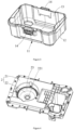
FIG. 11 is a perspective view of a fan housing inFIG. 2 . -
FIG. 12 is a perspective view of the fan housing inFIG. 2 from another angle. -
FIG. 13 is a cross-sectional view of a fan assembly inFIG. 2 . - The following describes the implementation of the disclosure through specific embodiments, and those skilled in the art can easily understand other advantages and effects of the disclosure from the content disclosed in this specification. The disclosure can also be implemented or applied through other different specific embodiments. Various details in this specification can also be modified or changed based on different viewpoints and applications without departing from the spirit of the disclosure. It should be noted that, the following embodiments and the features in the embodiments can be combined with each other without conflict. It should further be understood that the terms used in the examples of the disclosure are used to describe specific embodiments, instead of limiting the protection scope of the disclosure. The test methods that do not indicate specific conditions in the following examples are usually in accordance with conventional conditions, or conditions recommended by each manufacturer.
- It should be noted that the structure, scale, size, etc. of the drawings in this specification are merely for illustration of the disclosed content for understanding and reading by those skilled in the art, and do not intend to limit the restrictive conditions under which the disclosure can be implemented, so it has no technical significance. Any structural modification, proportional relationship change or size adjustment should still be within the scope of the technical content disclosed in the disclosure, without affecting the effects and objectives that can be achieved by the disclosure. At the same time, the terms such as "upper", "lower", "left", "right", "middle" and "one" cited in this specification are only for the convenience of description and are not used to limit the scope of the disclosure. The change or adjustment of the relative relationship should also be regarded as the applicable scope of the disclosure without substantial change in the technical content.
- The disclosure provides a fan assembly and a vacuum cleaner with the fan assembly. The vacuum cleaner can improve the suction effect to a certain extent, which improves work efficiency.
- Please refer to
FIG. 1 to FIG. 4 andFIG. 9 . The disclosure provides avacuum cleaner 100, thevacuum cleaner 100 includes a housing, adust suction assembly 5, a filter assembly 4 and a fan assembly 6. The housing is provided with adust collection cavity 13, amounting cavity 24, and a throughhole 221 communicating thedust collection cavity 13 and themounting cavity 24. Thedust suction assembly 5 is arranged on the housing and communicates with thedust collection cavity 13. The filter assembly 4 is arranged in thedust collection cavity 13. The fan assembly 6 is installed in themounting cavity 24. - Please refer to
FIG. 1 through FIG. 6 , the housing includes adust collector 1, amiddle cover assembly 2 arranged above thedust collector 1 and anupper cover assembly 3 covering themiddle cover assembly 2. Adust collection cavity 13 is formed between thedust collector 1 and themiddle cover assembly 2, and amounting cavity 24 is formed between theupper cover assembly 3 and themiddle cover assembly 2. Theupper cover assembly 3 is provided with anair inlet 30 communicating with thedust suction assembly 5, and an air outlet 30' is arranged between themiddle cover assembly 2 and theupper cover assembly 3. Thedust collector 1 is capable of being made into various shapes. In one embodiment, thedust collector 1 is rectangular and includes abottom wall 11 and aside wall 12 for connecting thebottom wall 11 and themiddle cover assembly 2. Theside walls 12 are provided with four and jointly define a housing space with thebottom wall 11. Themiddle cover assembly 2 protrudes into the housing space and forms adust collection cavity 13 with it, and the filter assembly 4 is housed in thedust collection cavity 13. The fan assembly 6 is arranged in themounting cavity 24 between themiddle cover assembly 2 and theupper cover assembly 3 and communicates with connecting thedust collector 1. Theside wall 12 of thedust collector 1 is also provided with a connectingpart 14 for connecting and fixing themiddle cover assembly 2 and theupper cover assembly 3. In this embodiment, the connectingpart 14 is configured as a movable buckle, so that themiddle cover assembly 2 and theupper cover assembly 3 are detachably fixed on thedust collector 1. - Please refer to
FIG.2 andFIG. 4 , themiddle cover assembly 2 includes amiddle cover body 21 arranged on thedust collector 1 and arecessed part 22 denting from themiddle cover body 21 toward the inside of thedust collector 1. In addition, the bottom wall of therecessed part 22 is provided with athrough hole 221 for communicating thedust collection cavity 13 and themounting cavity 24. In this embodiment, themiddle cover assembly 2 is embedded and fixed on thedust collector 1, and asealing ring 20 is also arranged between themiddle cover assembly 2 and thedust collector 1 to ensure that themiddle cover assembly 2 and thedust collector 1 are arranged tightly and prevent air from escaping into thedust collector 1 from the gap between mounting positions of themiddle cover assembly 2 and thedust collector 1 due to the pressure difference during the working process of thevacuum cleaner 100, which ensures the working efficiency of thevacuum cleaner 100. Specifically, during the assembly process of thevacuum cleaner 100 of the disclosure, at first, themiddle cover assembly 2 is fixed on thedust collector 1. Secondly, theupper cover assembly 3 is used to cover on themiddle cover assembly 2. At last, the connectingpart 14 is fastened to fix themiddle cover assembly 2 and theupper cover assembly 3 on thedust collector 1, which ensures that theupper cover assembly 3 and themiddle cover assembly 2 are stably connected with thedust collector 1 during the working process. - Please refer to
FIG. 2 ,FIG. 5 ,FIG. 6 andFIG.8 , theupper cover assembly 3 is used to cover on themiddle cover assembly 2 and is detachably connected with thedust collector 1 through the connectingpart 14. Abattery cavity 31 for housing abattery pack 200 is formed in theupper cover assembly 3, abattery insert 32 is arranged in thebattery cavity 31, and thebattery insert 32 is arranged corresponding to thebattery pack 200. Thebattery cavity 31 is formed through denting from a top of theupper cover assembly 3 toward the dust collector 1 (downward). Correspondingly, the position of themiddle cover assembly 2 corresponding to thebattery cavity 31 is recessed in the direction of thedust collector 1 to receive thebattery cavity 31, and thebattery cavity 31 is arranged on a different side of the recessedpart 22 of themiddle cover assembly 2. With this arrangement, amotor 61 and thebattery pack 200 are respectively located at two ends of thevacuum cleaner 100, so that the center of gravity of thevacuum cleaner 100 is approximately at the center of the housing, thereby avoiding the problem that thevacuum cleaner 100 is difficult to carry due to one side being too heavy. Thebattery pack 200 is housed in thebattery cavity 31 and plugged on thebattery insert 32 to provide power to thevacuum cleaner 100. An upper part of thebattery cavity 31 is provided with abattery pack cover 33 covering thebattery cavity 31, and thebattery pack cover 33 is movably connected with theupper cover assembly 3. In this embodiment, thebattery pack cover 33 and theupper cover assembly 3 are pivotally connected, and it can be understood that the connection method is not limited to this. With this arrangement, thebattery pack 200 of thevacuum cleaner 100 of the disclosure is capable of being mounted and removed only through opening thebattery pack cover 33, which improves the convenience to use thevacuum cleaner 100. Theupper cover assembly 3 is further provided with ahandle 34, and thehandle 34 is capable of being freely rotated on theupper cover assembly 3 to facilitate the use and movement of thevacuum cleaner 100. - Please refer to
FIG. 2 andFIG. 7 , thedust suction assembly 5 includes athroat pipe 51 and a dust suction accessory 52 connected with thethroat pipe 51. Thethroat pipe 51 includes a soft throat pipe 511 and a hard throat pipe 512 arranged on both sides of the soft throat 511. A first side of the soft throat pipe 511 is fixed on theupper cover assembly 3 through the hard throat pipe 512 and a connectingpart 513, and a second side is connected to the dust suction accessory 52 through the hard throat pipe 512, so that thethroat pipe 51 is capable of working through the dust suction accessory 52. The dust suction accessory 52 is capable of being a commonly used accessory of thevacuum cleaner 100 such as a floor brush, a flat vacuum, a round brush, a bed sheet brush, a sofa vacuum and so on, which means that the dust suction accessory 52 is capable of being selected and replaced according to the location where thevacuum cleaner 100 is used, and it is not limited here. - Please refer to
FIG. 2 ,FIG. 5 through FIG. 8 , anaccessory groove 35 for housing the dust suction accessory 52 is further formed in theupper cover assembly 3, and theaccessory groove 35 is recessed from the top of theupper cover assembly 3 toward thedust collector 1. Preferably, theaccessory groove 35 is located beside thebattery cavity 31 and is simultaneously covered by thebattery pack cover 33. With this arrangement, not only the dust suction accessory 52 can be stored well, be convenient for storage and avoid damage, but also it is convenient for access. Under the condition that the connection between theupper cover assembly 3 with themiddle cover assembly 2 and thedust collector 1 is maintained, the dust suction attachment 52 is capable of being replaced as needed. Theupper cover assembly 3 is also provided with a fixingcomponent 36 for fixing the hard throat 512 and agroove 37 for housing the soft throat 511. Thegroove 37 is formed through denting downwardly from an upper surface of theupper cover assembly 3. The fixingcomponent 36 is an arc-shaped gasket. In the storage state, the hard throat pipe 512 at the second side is placed on thegasket 36 to match thegroove 37 to jointly fix and limit thethroat pipe 51, which makes thethroat 51 be fixed on theupper cover assembly 3. - Please refer to
FIG. 2 ,FIG. 4 andFIG 10 throughFIG. 13 , the fan assembly 6 includes amotor 61, animpeller 62 and a fan housing. Theimpeller 62 is arranged on the output shaft of themotor 61 and is driven by themotor 61. Theimpeller 62 includes animpeller air outlet 622 and animpeller air inlet 621. Theimpeller air inlet 621 is located in the axial direction of theimpeller 62 and is communicated with the throughhole 221. Theimpeller air outlet 622 is located in the radial direction of theimpeller 62. Anair channel 631 is formed in the fan housing, theimpeller 62 is at least partially housed in the fan housing, and a height of the fan housing in the direction of a rotational axis increases along the direction of the airflow. In an embodiment, the fan assembly 6 is arranged in the recessedpart 22 of themiddle cover assembly 2. Specifically, themotor 61 is placed vertically. Theimpeller 62 is connected to the motor shaft 611 of themotor 61, and theimpeller 62 is housed in the recessedpart 22. Theimpeller air inlet 621 is located on the axis of theimpeller 62 and is directly opposite to the throughhole 221 on the bottom wall of the recessedpart 22. The outlet direction of theimpeller air outlet 622 is perpendicular to the axis of theimpeller 62. Therefore, when themotor 61 rotates, theimpeller 62 is driven to rotate and a high pressure area is formed at a top of theimpeller 62, so that the airflow moves from a low pressure area to a high pressure area, and a spiral upward airflow direction with the vertical direction as an axis is generated at the position of the fan assembly 6. The fan housing includes anupper housing 63 and a lower housing. Theupper housing 63 is a ring-shaped structure, and the bottom thereof is in a shape of an opening, so that the cross section in the direction of the rotational axis ofupper housing 63 of the fan housing is in an inverted U-shape. Aninner side wall 633 of theupper housing 63 is connected by a connectingplate 635, and the connectingplate 635 is provided with a through hole for the motor shaft 611 to pass through. The lower housing includes a bottom wall and side walls arranged in the circumferential direction along the bottom wall. The side walls of the lower housing are connected withouter side walls 634 of theupper housing 63, so that theupper housing 63 and the lower housing form anair channel 631. In this embodiment, the bottom wall of the recessedpart 22 of the middle cover assembly is the lower housing of the fan housing, and theair channel 631 is formed by the combination of theupper housing 63 of the fan housing and the bottom wall of the recessedpart 22 of themiddle cover assembly 2. Preferably, acircular arc structure 23 is formed at the position of the recessedpart 22 corresponding to theupper housing 63 of the fan housing, and thecircular arc structure 23 is used to guide high-pressure airflow around theimpeller 62 upwards into theair channel 631. In other embodiments, the lower housing can also be set up separately, so that anair channel 631 is formed between theupper housing 63 and the lower housing, which is not limited to this. - Please refer to
FIG. 9 through FIG. 11 , theupper housing 63 of the fan housing is provided with a first end A, aspiral part 632 spirally extending upward from the first end A, and a second end B located at the end of thespiral part 632. In other words, thespiral part 632 spirals from the first end A to the second end B until the first end A and the second end B merge. At this time, a round of spiral is completed. Afan air outlet 636 is arranged at the second end B of theupper housing 63 of the fan housing. Thefan air outlet 636 communicates with the air outlet 30'. The high-pressure airflow spirally flows in theair channel 631 and is finally discharged from the air outlet 30'. After the high-pressure airflow is discharged from the air outlet 30', a negative pressure is formed inside thedust suction assembly 5, which encourages external air to enter the soft throat pipe 511 from the dust suction accessory 52, and the function of thevacuum cleaner 100 is completed at this time. In this embodiment, the base surfaces of the first end A, thespiral part 632, and the second end B are in the same plane, and the height of thespiral part 632 close to the first end A is lower than the height of thespiral part 632 close to the second end B, so that the top surface of thespiral part 632 is spiral. The top surface of thespiral part 632 is designed as a spiral shape to form aspiral air channel 631 inside the fan housing. Of course, in other embodiments, the overall height of thespiral part 632 may be kept constant, and then a groove is formed at the bottom of thespiral part 632 to form aspiral air channel 631, which is not limited here. In this embodiment, the top surface of thespiral part 632 gradually spirally extends upward along the helix angle α. The helix angle α is preferably a constant angle. As shown inFIG. 11 , the helix angle α is the angle between a tangent of the helix on the top surface and a plane perpendicular to a helix axis (i.e., the horizontal plane). In this embodiment, the helix angle is one of the important parameters that affect the wind resistance of the air channel and the work efficiency. - Table 1 shows that the
upper housings 63 of the fan housing with different helix angles are applied to thevacuum cleaner 100. When thevacuum cleaner 100 is working normally (which means when the working voltage remains the same), current, shaft power, fluid power, flow, total pressure and work efficiency will be analyzed and then specific values can be obtained. The specific values are shown in the table below.Table 1 helix angle voltage current Shaft power fluid power flow total pressure work efficiency ° V A W W 1/ s KPa % 3° 36.0 9.17 330 95 10.5 7.2 28.8% 8° 36.0 8.53 307.1 98.2 11.7 8.4 32% 12° 36.0 9.35 336.6 108.3 11.2 9.67 32.2% 20° 36.0 8.55 307.8 101 11.7 8.6 32.8% 35° 36.0 8.89 320 108 12.1 8.9 34% - It can be seen from the above table: under the voltage of 36V, the helix angle is set between 3° to 35°. When the helix angle is 3°, the working efficiency of the
vacuum cleaner 100 reaches 28.8%, and when the helix angle is 8°, the working efficiency of thevacuum cleaner 100reaches 32%. At this time, the current value, the shaft power and the total voltage are all low. When the helix angle is 12°, the working efficiency of thevacuum cleaner 100 is 32.2%, and the current value, the shaft power, the fluid power and the total pressure are all high at this time. When the helix angle is 20°, the working efficiency of thevacuum cleaner 100 is 32.8%. When the helix angle is 35°, the working efficiency of thevacuum cleaner 100reaches 34%, which is the highest value, and at the same time the flow also reaches the maximum. From this data, it can be concluded that under the same voltage, when the helix angle of thespiral part 632 is between 3 degrees to 35 degrees, the working efficiency of thevacuum cleaner 100 will gradually increase and reach the highest value when the helix angle is 35°. Therefore, the helix angle of the top surface of thespiral part 632 is preferably 3 degrees to 35 degrees. Such a design is beneficial to reduce wind pressure loss and wind resistance, improve air flow, and increase work efficiency by about 10% to a certain extent. - Please refer to
FIG. 13 , in one embodiment, themotor 61 can be selected as a brushless motor. The brushless motor is not provided with brushes, so that the brushless motor can rotate at a high speed with low noise. Secondly, the volume of the brushless motor is smaller, which can free up more space for housing the battery assembly and extend the endurance time of thevacuum cleaner 100. The brushless motor is also provided with afan blade 612 for heat dissipation. Thefan blade 612 is located between the brushless motor and theimpeller 62. When the brushless motor is working, thefan blade 612 is driven by the brushless motor to rotate, thereby driving wind from an end of the brushless motor away from thefan blade 612 into the brushless motor. Then the wind is discharged from the gap between the brushless motor and the recessedpart 22 of themiddle cover assembly 2, which means that the cooling wind enters the brushless motor along the direction C, and then exits along the direction D, so that heat is dissipated from the brushless motor. In other embodiments, thefan blade 612 is also capable of being arranged at the end of the brushless motor away from theimpeller 62, the cooling wind is introduced into the brushless motor along the direction C, and then discharged along the direction D. Or the cooling wind enters the brushless motor along the opposite direction of the direction D, and then exits along the opposite direction of the direction C. - The rated rotating speed of the
impeller 62 is set between 20,000 rpm to 80,000 rpm, and the diameter of theimpeller 62 is set between 60 mm and 90 mm. With this arrangement, the total pressure efficiency of thevacuum cleaner 100 is relatively high, so that the dust suction efficiency of thevacuum cleaner 100 can be improved. The rotating speed of theimpeller 62 may also be greater than 80,000 rpm, and the diameter of theimpeller 62 may be less than 60 mm or greater than 90 mm, which is not a limited herein. Preferably, the diameter of theimpeller 62 is between 60 mm to 80 mm. When the rated rotating speed of theimpeller 62 is set to 40,000 rpm, and the diameter of theimpeller 62 is set to 70 mm, theimpeller 62 has the highest total pressure efficiency at this time. Preferably, the diameter of theimpeller 62 is set to 60 mm. With this arrangement, when the rotating speed of theimpeller 62 is between 20,000 rpm to 80,000 rpm, thevacuum cleaner 100 has a better total pressure efficiency, so that the fan suction assembly 6 is capable of being applied widely. - Please refer to
FIG. 2 andFIG. 10 , the filter assembly 4 includes afilter element 41. Thefilter element 41 is fixedly arranged in thedust collection cavity 13 formed by thedust collector 1 and themiddle cover assembly 2, located below theimpeller 62, and communicates with the throughhole 221 in the bottom wall of the recessedpart 22 of themiddle cover assembly 2, so that when theimpeller 62 rotates, the filtered gas will be sucked into theimpeller 62 and a high-pressure airflow is formed at the top of theimpeller 62, which makes the high-pressure airflow flows out along thespiral air channel 631 inside the fan housing. Since the specific structure of the filter assembly 4 can adopt conventional technical solutions, it will not be repeated here. - In summary, the air flow direction of the
vacuum cleaner 100 of the disclosure is: the air flow carries impurities into thedust collector 1 through the dust suction accessory 52, thethroat pipe 51 and theair inlet 30. After filtered by the filter assembly 4, the impurities will fall into thedust collector 1. The air flow continues to flow along thespiral air channel 631 in the fan housing, so that when themotor 61 rotates, theimpeller 62 can be driven to rotate and a high-pressure air flow can be formed at the top of theimpeller 62. Then the high-pressure air flows out from the air outlet 30' along thespiral air channel 631 in the fan housing. Thespiral air channel 631 is beneficial to reduce wind pressure loss and wind resistance, improves air flow, and improves suction effect and working efficiency of thevacuum cleaner 100 to a certain extent. - The above embodiments are only used to illustrate the technical solutions of the disclosure and not to limit them. Although the disclosure has been described in detail with reference to preferred embodiments, those of ordinary skill in the art should understand that the technical solutions of the disclosure can be modified or equivalently replaced without departing from the scope of protection defined by the appended claims.
Claims (12)
- A vacuum cleaner, comprising:a housing, wherein a dust collection cavity (13), a mounting cavity (24), and a through hole (221) communicating the dust collection cavity (13) and the mounting cavity (24) are arranged in the housing,a dust suction assembly (5), one end thereof passing through the housing and extending to the dust collection cavity (13),a filter assembly (4), arranged in the dust collection cavity (13), anda fan assembly (6), arranged in the mounting cavity (24), and comprising:an impeller (62), driven by a motor (61), the impeller (62) comprising an impeller air inlet (621) located in an axial direction of the impeller (62) and an impeller air outlet (622) located in a radial direction of the impeller (62), anda fan housing, defining an air channel (631) therein, the impeller (62) being at least partially housed in the fan housing, the impeller (62) rotating relative to the fan housing about a rotational axis, a generated airflow entering the air channel (631) during a rotation of the impeller (62), and a height of the fan housing in a direction of the rotational axis increasing along a direction of the air flow, characterized in that the housing comprising a dust collector (1), a middle cover assembly (2) and an upper cover assembly (3), the middle cover assembly (2) is arranged above the dust collector (1) and forms the dust collection cavity (13) with the dust collector (1), the upper cover assembly (3) is arranged above the middle cover assembly (2) and forms the mounting cavity (24) with the middle cover assembly (2).
- The vacuum cleaner according to claim 1, wherein
the fan housing comprises an upper housing (63) and a lower housing, the upper housing (63) has an inverted U-shaped cross section along the direction of the rotational axis, and the lower housing is arranged below the upper housing (63) and being a spiral air channel with the upper housing (63). - The vacuum cleaner according to claim 2, wherein
the upper housing (63) comprises a first end (A), a spiral part (632) spirally extending upward from the first end (A), and a second end (B) located at an end of the spiral part (632), and base surfaces of the first end (A), the spiral part (632), and the second end (B) are in a same plane. - The vacuum cleaner according to claim 3, whereinthe lower housing comprises a bottom wall (11) and a side wall (12) arranged along a circumferential direction of the bottom wall (11), and the side wall (12) of the lower housing is connected with an side wall of the upper housing (63),a top surface of the spiral part (632) is spiraling in the direction of the airflow, anda top surface of the spiral part (632) gradually spirally extends upward along a helix angle and the helix angle is between 3° and 35°.
- The vacuum cleaner according to claim 1, whereina ratio of a rated rotating speed of the impeller (62) to a diameter of the impeller (62) is not less than 220, the rated rotating speed of the impeller (62) is not less than 20000 rpm, andthe diameter of the impeller (62) is between 60mm and 80 mm.
- The vacuum cleaner according to claim 2, wherein
the middle cover assembly (2) comprises a middle cover body (21) and a recessed part (22) denting downwardly from the middle cover body (21), the through hole (221) is arranged on a bottom wall of the recessed part (22), the fan assembly (6) is housed in the recessed part (22), the bottom wall of the recessed part (22) is the lower housing of the fan housing, and a circular arc structure (23) is formed at a position of the recessed part (22) corresponding to the upper housing (63) to guide high-pressure airflow around the impeller (62) upwards into the air channel (631). - The vacuum cleaner according to claim 3, whereina height of the spiral part (632) close to the first end (A) is lower than a height of the spiral part (632) close to the second end (B), and a top surface of the spiral part (632) is spiraling in the direction of the airflow, andthe upper cover assembly (3) comprises a battery cavity (31) housing a battery pack (200), a battery pack cover (33) is arranged on an upper part of the battery cavity (31), and the battery pack cover (33) is movably connected with the upper cover assembly (3).
- The vacuum cleaner according to claim 2, wherein
the dust suction assembly (5) is arranged on the upper cover assembly (3), the dust suction assembly (5) comprises a throat pipe (51) and a dust suction accessory (52) connected to the throat pipe (51), the throat pipe (51) comprises a soft throat pipe (511) and a hard throat pipe (512) arranged on both sides of the soft throat pipe (511), a first side of the soft throat pipe (511) is fixed on the upper cover assembly (3) through the hard throat pipe (512), and a second side of the soft throat pipe (511) is connected to the dust suction accessory (5) through the hard throat pipe (512). - The vacuum cleaner according to claim 8, whereinthe upper cover assembly (3) further comprises an accessory groove (35) housing the dust suction accessory (52), andthe upper cover assembly (3) is provided with a fixing component (36) to fix the hard throat pipe (512) and a groove (37) to house the soft throat pipe (511), the fixing component (36) is a circular arc-shaped gasket, as in a storing state, the hard throat pipe (512) at the second side is located on the gasket to match the groove (37) to fix and limit the throat pipe (51).
- The vacuum cleaner according to claim 2, wherein
the upper cover assembly (3) is provided with an air inlet (30) communicated with the dust suction assembly (5), and an air outlet (30') is arranged between the middle cover assembly (2) and the upper cover assembly (3). - The vacuum cleaner according to claim 1, wherein
the motor (61) is a brushless motor. - The vacuum cleaner according to claim 11, wherein
the brushless motor (61) comprises a fan blade (612) for heat dissipation, and the fan blade (612) is arranged between the brushless motor (61) and the impeller (62).
Applications Claiming Priority (3)
| Application Number | Priority Date | Filing Date | Title |
|---|---|---|---|
| CN202011008165.5A CN112006603A (en) | 2020-09-23 | 2020-09-23 | Vacuum cleaner |
| CN202011414998.1A CN112426092A (en) | 2020-12-07 | 2020-12-07 | Brushless air suction assembly and brushless dry and wet dust collector |
| PCT/CN2021/118553 WO2022063003A1 (en) | 2020-09-23 | 2021-09-15 | Fan assembly and vacuum cleaner with fan assembly |
Publications (3)
| Publication Number | Publication Date |
|---|---|
| EP4203758A1 EP4203758A1 (en) | 2023-07-05 |
| EP4203758A4 EP4203758A4 (en) | 2024-03-06 |
| EP4203758B1 true EP4203758B1 (en) | 2025-02-19 |
Family
ID=80846242
Family Applications (1)
| Application Number | Title | Priority Date | Filing Date |
|---|---|---|---|
| EP21871374.1A Active EP4203758B1 (en) | 2020-09-23 | 2021-09-15 | Fan assembly and vacuum cleaner with fan assembly |
Country Status (3)
| Country | Link |
|---|---|
| US (1) | US12484744B2 (en) |
| EP (1) | EP4203758B1 (en) |
| WO (1) | WO2022063003A1 (en) |
Families Citing this family (1)
| Publication number | Priority date | Publication date | Assignee | Title |
|---|---|---|---|---|
| USD1089912S1 (en) * | 2022-01-13 | 2025-08-19 | Emerson Electric Co. | Wet/dry vacuum cleaner |
Citations (20)
| Publication number | Priority date | Publication date | Assignee | Title |
|---|---|---|---|---|
| DE8704717U1 (en) | 1987-03-31 | 1988-02-25 | Zubler Gerätebau GmbH, 7910 Neu-Ulm | Brushless industrial vacuum cleaner |
| DE9113641U1 (en) | 1991-11-04 | 1992-02-27 | Obermüller, Herbert, 6464 Linsengericht | Door-accessible industrial vacuum cleaner with rectangular column-shaped housing, based on a cleanable HEPA filter cell as a working filter, pneumatic cleaning technology, and a HEPA filter cell as a safety post-filter |
| US6158083A (en) | 1998-08-31 | 2000-12-12 | Emerson Electric, Co. | Wet/dry vacuum with reduced operating noise |
| WO2001024676A2 (en) | 1999-09-28 | 2001-04-12 | Royal Appliance Mfg. Co. | Impeller and housing assembly with reduced noise and improved airflow |
| US6777844B2 (en) | 2000-10-24 | 2004-08-17 | Rexair, Inc. | Brushless motor |
| EP2545766A1 (en) | 2011-07-14 | 2013-01-16 | Black & Decker Inc. | A debris blowing and/or vacuum appliance |
| EP2644072A2 (en) | 2012-03-27 | 2013-10-02 | Black & Decker Inc. | Wet and dry vacuum cleaner |
| CN203776830U (en) | 2014-03-18 | 2014-08-20 | 天佑电器(苏州)有限公司 | Vacuum cleaner |
| EP2987441A1 (en) | 2014-08-20 | 2016-02-24 | Octrooifabriek B.V. | Vacuum cleaning device, method of its use and method of its manufacture |
| CN109276182A (en) | 2017-07-20 | 2019-01-29 | 上海耐柯环保科技有限公司 | A kind of semi-automatic industrial dust collector |
| CN208905592U (en) | 2017-12-08 | 2019-05-28 | 东昌电机(深圳)有限公司 | A kind of industrial dust collector |
| CN208973659U (en) | 2017-12-25 | 2019-06-14 | 常州格力博有限公司 | Dust catcher |
| CN110215161A (en) | 2019-05-29 | 2019-09-10 | 尚科宁家(中国)科技有限公司 | A kind of clean robot and dust-collecting box |
| CN209458188U (en) | 2019-01-11 | 2019-10-01 | 日本电产株式会社 | Centrifugal fan and dust catcher |
| CN211187036U (en) | 2019-11-01 | 2020-08-07 | 苏州欧圣电气股份有限公司 | a vacuum cleaner |
| CN211355203U (en) | 2019-12-06 | 2020-08-28 | 格力博(江苏)股份有限公司 | Vacuum cleaner |
| CN112006603A (en) | 2020-09-23 | 2020-12-01 | 格力博(江苏)股份有限公司 | Vacuum cleaner |
| CN212307705U (en) | 2020-09-23 | 2021-01-08 | 格力博(江苏)股份有限公司 | Vacuum cleaner |
| CN112426092A (en) | 2020-12-07 | 2021-03-02 | 格力博(江苏)股份有限公司 | Brushless air suction assembly and brushless dry and wet dust collector |
| CN109008797B (en) | 2017-06-09 | 2024-07-02 | 天佑电器(苏州)有限公司 | Dust collector |
Family Cites Families (5)
| Publication number | Priority date | Publication date | Assignee | Title |
|---|---|---|---|---|
| US5443362A (en) * | 1994-03-16 | 1995-08-22 | The Hoover Company | Air turbine |
| CA2478295A1 (en) * | 2002-03-12 | 2003-09-18 | Cube Investments Limited | Suction motor for vacuum cleaner |
| CN203756560U (en) | 2014-01-02 | 2014-08-06 | 常州格力博有限公司 | Double-section centrifugal draught fan |
| KR101781694B1 (en) * | 2015-09-24 | 2017-09-25 | 엘지전자 주식회사 | Centrifugal fan |
| CN112168057B (en) * | 2019-07-04 | 2025-03-14 | 苏州宝时得电动工具有限公司 | Vacuum cleaner |
-
2021
- 2021-09-15 EP EP21871374.1A patent/EP4203758B1/en active Active
- 2021-09-15 WO PCT/CN2021/118553 patent/WO2022063003A1/en not_active Ceased
-
2023
- 2023-01-12 US US18/153,379 patent/US12484744B2/en active Active
Patent Citations (20)
| Publication number | Priority date | Publication date | Assignee | Title |
|---|---|---|---|---|
| DE8704717U1 (en) | 1987-03-31 | 1988-02-25 | Zubler Gerätebau GmbH, 7910 Neu-Ulm | Brushless industrial vacuum cleaner |
| DE9113641U1 (en) | 1991-11-04 | 1992-02-27 | Obermüller, Herbert, 6464 Linsengericht | Door-accessible industrial vacuum cleaner with rectangular column-shaped housing, based on a cleanable HEPA filter cell as a working filter, pneumatic cleaning technology, and a HEPA filter cell as a safety post-filter |
| US6158083A (en) | 1998-08-31 | 2000-12-12 | Emerson Electric, Co. | Wet/dry vacuum with reduced operating noise |
| WO2001024676A2 (en) | 1999-09-28 | 2001-04-12 | Royal Appliance Mfg. Co. | Impeller and housing assembly with reduced noise and improved airflow |
| US6777844B2 (en) | 2000-10-24 | 2004-08-17 | Rexair, Inc. | Brushless motor |
| EP2545766A1 (en) | 2011-07-14 | 2013-01-16 | Black & Decker Inc. | A debris blowing and/or vacuum appliance |
| EP2644072A2 (en) | 2012-03-27 | 2013-10-02 | Black & Decker Inc. | Wet and dry vacuum cleaner |
| CN203776830U (en) | 2014-03-18 | 2014-08-20 | 天佑电器(苏州)有限公司 | Vacuum cleaner |
| EP2987441A1 (en) | 2014-08-20 | 2016-02-24 | Octrooifabriek B.V. | Vacuum cleaning device, method of its use and method of its manufacture |
| CN109008797B (en) | 2017-06-09 | 2024-07-02 | 天佑电器(苏州)有限公司 | Dust collector |
| CN109276182A (en) | 2017-07-20 | 2019-01-29 | 上海耐柯环保科技有限公司 | A kind of semi-automatic industrial dust collector |
| CN208905592U (en) | 2017-12-08 | 2019-05-28 | 东昌电机(深圳)有限公司 | A kind of industrial dust collector |
| CN208973659U (en) | 2017-12-25 | 2019-06-14 | 常州格力博有限公司 | Dust catcher |
| CN209458188U (en) | 2019-01-11 | 2019-10-01 | 日本电产株式会社 | Centrifugal fan and dust catcher |
| CN110215161A (en) | 2019-05-29 | 2019-09-10 | 尚科宁家(中国)科技有限公司 | A kind of clean robot and dust-collecting box |
| CN211187036U (en) | 2019-11-01 | 2020-08-07 | 苏州欧圣电气股份有限公司 | a vacuum cleaner |
| CN211355203U (en) | 2019-12-06 | 2020-08-28 | 格力博(江苏)股份有限公司 | Vacuum cleaner |
| CN112006603A (en) | 2020-09-23 | 2020-12-01 | 格力博(江苏)股份有限公司 | Vacuum cleaner |
| CN212307705U (en) | 2020-09-23 | 2021-01-08 | 格力博(江苏)股份有限公司 | Vacuum cleaner |
| CN112426092A (en) | 2020-12-07 | 2021-03-02 | 格力博(江苏)股份有限公司 | Brushless air suction assembly and brushless dry and wet dust collector |
Non-Patent Citations (1)
| Title |
|---|
| Q. GUO AND X. ZHAO: "Principles and Technical Applications of Brushless DC Motors", 2008, CHINA ELECTRIC POWER PRESS,, Beijing, ISBN: 978-7-5083-5939-7, article D5-, pages: 1, 2, 185, 189 |
Also Published As
| Publication number | Publication date |
|---|---|
| US20230148808A1 (en) | 2023-05-18 |
| WO2022063003A1 (en) | 2022-03-31 |
| US12484744B2 (en) | 2025-12-02 |
| EP4203758A4 (en) | 2024-03-06 |
| EP4203758A1 (en) | 2023-07-05 |
Similar Documents
| Publication | Publication Date | Title |
|---|---|---|
| CA2281241C (en) | Wet/dry vacuum with reduced operating noise | |
| CN1264569A (en) | Electric broom | |
| EP4203758B1 (en) | Fan assembly and vacuum cleaner with fan assembly | |
| TW202002876A (en) | Cleaner | |
| CN114174685A (en) | Blower | |
| CN212307705U (en) | Vacuum cleaner | |
| CN112426092A (en) | Brushless air suction assembly and brushless dry and wet dust collector | |
| CN211355203U (en) | Vacuum cleaner | |
| KR100409173B1 (en) | Electric vacuum cleaner | |
| CN112545365A (en) | Floating shell, rolling brush mechanism, dust collection assembly, dust collection system and sweeping robot | |
| CN112006603A (en) | Vacuum cleaner | |
| TW200813334A (en) | Apparatus of centrifugal fan and a dust-collecting module of using the same | |
| WO2022134611A1 (en) | Dust collecting box and sweeping robot | |
| CN112450797B (en) | Vacuum cleaner with rotating wheel assembly | |
| CN219250040U (en) | Cleaning apparatus | |
| CN207384203U (en) | A low-pressure vacuum cleaner powertrain | |
| CN213508249U (en) | Handheld Hair Dryer | |
| CN101153615A (en) | Centrifugal fan and dust collecting box module with same | |
| CN213185728U (en) | Air duct matching structure of dust collector motor | |
| EP4000804A1 (en) | Sanding tool | |
| US20040261218A1 (en) | Electric vacuum brush for vacuum cleaners | |
| JP2001003898A (en) | Electric blower and vacuum cleaner using it | |
| CN220059960U (en) | Fan assembly and cleaning device | |
| CN220586083U (en) | Driving motor, submersible motor and submersible pump | |
| CN218304709U (en) | Vertical dust collector |
Legal Events
| Date | Code | Title | Description |
|---|---|---|---|
| STAA | Information on the status of an ep patent application or granted ep patent |
Free format text: STATUS: THE INTERNATIONAL PUBLICATION HAS BEEN MADE |
|
| PUAI | Public reference made under article 153(3) epc to a published international application that has entered the european phase |
Free format text: ORIGINAL CODE: 0009012 |
|
| STAA | Information on the status of an ep patent application or granted ep patent |
Free format text: STATUS: REQUEST FOR EXAMINATION WAS MADE |
|
| 17P | Request for examination filed |
Effective date: 20230330 |
|
| AK | Designated contracting states |
Kind code of ref document: A1 Designated state(s): AL AT BE BG CH CY CZ DE DK EE ES FI FR GB GR HR HU IE IS IT LI LT LU LV MC MK MT NL NO PL PT RO RS SE SI SK SM TR |
|
| DAV | Request for validation of the european patent (deleted) | ||
| DAX | Request for extension of the european patent (deleted) | ||
| A4 | Supplementary search report drawn up and despatched |
Effective date: 20240202 |
|
| RIC1 | Information provided on ipc code assigned before grant |
Ipc: A47L 7/00 20060101ALI20240129BHEP Ipc: A47L 9/28 20060101ALI20240129BHEP Ipc: A47L 9/16 20060101ALI20240129BHEP Ipc: A47L 9/00 20060101AFI20240129BHEP |
|
| GRAP | Despatch of communication of intention to grant a patent |
Free format text: ORIGINAL CODE: EPIDOSNIGR1 |
|
| STAA | Information on the status of an ep patent application or granted ep patent |
Free format text: STATUS: GRANT OF PATENT IS INTENDED |
|
| INTG | Intention to grant announced |
Effective date: 20241128 |
|
| GRAS | Grant fee paid |
Free format text: ORIGINAL CODE: EPIDOSNIGR3 |
|
| GRAA | (expected) grant |
Free format text: ORIGINAL CODE: 0009210 |
|
| STAA | Information on the status of an ep patent application or granted ep patent |
Free format text: STATUS: THE PATENT HAS BEEN GRANTED |
|
| AK | Designated contracting states |
Kind code of ref document: B1 Designated state(s): AL AT BE BG CH CY CZ DE DK EE ES FI FR GB GR HR HU IE IS IT LI LT LU LV MC MK MT NL NO PL PT RO RS SE SI SK SM TR |
|
| REG | Reference to a national code |
Ref country code: GB Ref legal event code: FG4D |
|
| REG | Reference to a national code |
Ref country code: CH Ref legal event code: EP |
|
| REG | Reference to a national code |
Ref country code: IE Ref legal event code: FG4D |
|
| REG | Reference to a national code |
Ref country code: DE Ref legal event code: R096 Ref document number: 602021026550 Country of ref document: DE |
|
| REG | Reference to a national code |
Ref country code: NL Ref legal event code: MP Effective date: 20250219 |
|
| PG25 | Lapsed in a contracting state [announced via postgrant information from national office to epo] |
Ref country code: RS Free format text: LAPSE BECAUSE OF FAILURE TO SUBMIT A TRANSLATION OF THE DESCRIPTION OR TO PAY THE FEE WITHIN THE PRESCRIBED TIME-LIMIT Effective date: 20250519 |
|
| PG25 | Lapsed in a contracting state [announced via postgrant information from national office to epo] |
Ref country code: FI Free format text: LAPSE BECAUSE OF FAILURE TO SUBMIT A TRANSLATION OF THE DESCRIPTION OR TO PAY THE FEE WITHIN THE PRESCRIBED TIME-LIMIT Effective date: 20250219 |
|
| PG25 | Lapsed in a contracting state [announced via postgrant information from national office to epo] |
Ref country code: PL Free format text: LAPSE BECAUSE OF FAILURE TO SUBMIT A TRANSLATION OF THE DESCRIPTION OR TO PAY THE FEE WITHIN THE PRESCRIBED TIME-LIMIT Effective date: 20250219 |
|
| PG25 | Lapsed in a contracting state [announced via postgrant information from national office to epo] |
Ref country code: ES Free format text: LAPSE BECAUSE OF FAILURE TO SUBMIT A TRANSLATION OF THE DESCRIPTION OR TO PAY THE FEE WITHIN THE PRESCRIBED TIME-LIMIT Effective date: 20250219 |
|
| REG | Reference to a national code |
Ref country code: LT Ref legal event code: MG9D |
|
| PG25 | Lapsed in a contracting state [announced via postgrant information from national office to epo] |
Ref country code: IS Free format text: LAPSE BECAUSE OF FAILURE TO SUBMIT A TRANSLATION OF THE DESCRIPTION OR TO PAY THE FEE WITHIN THE PRESCRIBED TIME-LIMIT Effective date: 20250619 Ref country code: NO Free format text: LAPSE BECAUSE OF FAILURE TO SUBMIT A TRANSLATION OF THE DESCRIPTION OR TO PAY THE FEE WITHIN THE PRESCRIBED TIME-LIMIT Effective date: 20250519 |
|
| PG25 | Lapsed in a contracting state [announced via postgrant information from national office to epo] |
Ref country code: NL Free format text: LAPSE BECAUSE OF FAILURE TO SUBMIT A TRANSLATION OF THE DESCRIPTION OR TO PAY THE FEE WITHIN THE PRESCRIBED TIME-LIMIT Effective date: 20250219 |
|
| PG25 | Lapsed in a contracting state [announced via postgrant information from national office to epo] |
Ref country code: HR Free format text: LAPSE BECAUSE OF FAILURE TO SUBMIT A TRANSLATION OF THE DESCRIPTION OR TO PAY THE FEE WITHIN THE PRESCRIBED TIME-LIMIT Effective date: 20250219 |
|
| PG25 | Lapsed in a contracting state [announced via postgrant information from national office to epo] |
Ref country code: LV Free format text: LAPSE BECAUSE OF FAILURE TO SUBMIT A TRANSLATION OF THE DESCRIPTION OR TO PAY THE FEE WITHIN THE PRESCRIBED TIME-LIMIT Effective date: 20250219 Ref country code: PT Free format text: LAPSE BECAUSE OF FAILURE TO SUBMIT A TRANSLATION OF THE DESCRIPTION OR TO PAY THE FEE WITHIN THE PRESCRIBED TIME-LIMIT Effective date: 20250620 |
|
| PG25 | Lapsed in a contracting state [announced via postgrant information from national office to epo] |
Ref country code: GR Free format text: LAPSE BECAUSE OF FAILURE TO SUBMIT A TRANSLATION OF THE DESCRIPTION OR TO PAY THE FEE WITHIN THE PRESCRIBED TIME-LIMIT Effective date: 20250520 Ref country code: BG Free format text: LAPSE BECAUSE OF FAILURE TO SUBMIT A TRANSLATION OF THE DESCRIPTION OR TO PAY THE FEE WITHIN THE PRESCRIBED TIME-LIMIT Effective date: 20250219 |
|
| REG | Reference to a national code |
Ref country code: AT Ref legal event code: MK05 Ref document number: 1767487 Country of ref document: AT Kind code of ref document: T Effective date: 20250219 |
|
| PG25 | Lapsed in a contracting state [announced via postgrant information from national office to epo] |
Ref country code: SE Free format text: LAPSE BECAUSE OF FAILURE TO SUBMIT A TRANSLATION OF THE DESCRIPTION OR TO PAY THE FEE WITHIN THE PRESCRIBED TIME-LIMIT Effective date: 20250219 |
|
| PG25 | Lapsed in a contracting state [announced via postgrant information from national office to epo] |
Ref country code: SM Free format text: LAPSE BECAUSE OF FAILURE TO SUBMIT A TRANSLATION OF THE DESCRIPTION OR TO PAY THE FEE WITHIN THE PRESCRIBED TIME-LIMIT Effective date: 20250219 |
|
| PG25 | Lapsed in a contracting state [announced via postgrant information from national office to epo] |
Ref country code: DK Free format text: LAPSE BECAUSE OF FAILURE TO SUBMIT A TRANSLATION OF THE DESCRIPTION OR TO PAY THE FEE WITHIN THE PRESCRIBED TIME-LIMIT Effective date: 20250219 |
|
| PGFP | Annual fee paid to national office [announced via postgrant information from national office to epo] |
Ref country code: DE Payment date: 20250919 Year of fee payment: 5 |
|
| PG25 | Lapsed in a contracting state [announced via postgrant information from national office to epo] |
Ref country code: IT Free format text: LAPSE BECAUSE OF FAILURE TO SUBMIT A TRANSLATION OF THE DESCRIPTION OR TO PAY THE FEE WITHIN THE PRESCRIBED TIME-LIMIT Effective date: 20250219 |
|
| PGFP | Annual fee paid to national office [announced via postgrant information from national office to epo] |
Ref country code: GB Payment date: 20250923 Year of fee payment: 5 |
|
| PG25 | Lapsed in a contracting state [announced via postgrant information from national office to epo] |
Ref country code: AT Free format text: LAPSE BECAUSE OF FAILURE TO SUBMIT A TRANSLATION OF THE DESCRIPTION OR TO PAY THE FEE WITHIN THE PRESCRIBED TIME-LIMIT Effective date: 20250219 |
|
| PGFP | Annual fee paid to national office [announced via postgrant information from national office to epo] |
Ref country code: FR Payment date: 20250925 Year of fee payment: 5 |
|
| PG25 | Lapsed in a contracting state [announced via postgrant information from national office to epo] |
Ref country code: EE Free format text: LAPSE BECAUSE OF FAILURE TO SUBMIT A TRANSLATION OF THE DESCRIPTION OR TO PAY THE FEE WITHIN THE PRESCRIBED TIME-LIMIT Effective date: 20250219 Ref country code: CZ Free format text: LAPSE BECAUSE OF FAILURE TO SUBMIT A TRANSLATION OF THE DESCRIPTION OR TO PAY THE FEE WITHIN THE PRESCRIBED TIME-LIMIT Effective date: 20250219 |
|
| PG25 | Lapsed in a contracting state [announced via postgrant information from national office to epo] |
Ref country code: RO Free format text: LAPSE BECAUSE OF FAILURE TO SUBMIT A TRANSLATION OF THE DESCRIPTION OR TO PAY THE FEE WITHIN THE PRESCRIBED TIME-LIMIT Effective date: 20250219 |
|
| PG25 | Lapsed in a contracting state [announced via postgrant information from national office to epo] |
Ref country code: SK Free format text: LAPSE BECAUSE OF FAILURE TO SUBMIT A TRANSLATION OF THE DESCRIPTION OR TO PAY THE FEE WITHIN THE PRESCRIBED TIME-LIMIT Effective date: 20250219 |
|
| REG | Reference to a national code |
Ref country code: DE Ref legal event code: R026 Ref document number: 602021026550 Country of ref document: DE |
|
| PLBI | Opposition filed |
Free format text: ORIGINAL CODE: 0009260 |
|
| PLAX | Notice of opposition and request to file observation + time limit sent |
Free format text: ORIGINAL CODE: EPIDOSNOBS2 |