EP4203375A1 - Method and apparatus for transmitting synchronized broadcast information - Google Patents
Method and apparatus for transmitting synchronized broadcast information Download PDFInfo
- Publication number
- EP4203375A1 EP4203375A1 EP23156768.6A EP23156768A EP4203375A1 EP 4203375 A1 EP4203375 A1 EP 4203375A1 EP 23156768 A EP23156768 A EP 23156768A EP 4203375 A1 EP4203375 A1 EP 4203375A1
- Authority
- EP
- European Patent Office
- Prior art keywords
- ssb
- candidate
- ssbs
- transmission
- time interval
- Prior art date
- Legal status (The legal status is an assumption and is not a legal conclusion. Google has not performed a legal analysis and makes no representation as to the accuracy of the status listed.)
- Pending
Links
- 238000000034 method Methods 0.000 title claims abstract description 56
- 230000001360 synchronised effect Effects 0.000 title abstract description 8
- 230000005540 biological transmission Effects 0.000 claims abstract description 322
- 101710093976 Plasmid-derived single-stranded DNA-binding protein Proteins 0.000 claims description 137
- 235000019527 sweetened beverage Nutrition 0.000 claims description 137
- 230000004044 response Effects 0.000 claims description 10
- 238000010408 sweeping Methods 0.000 description 29
- 238000012545 processing Methods 0.000 description 19
- 101000824890 Homo sapiens SOSS complex subunit B2 Proteins 0.000 description 18
- 102100022330 SPRY domain-containing SOCS box protein 2 Human genes 0.000 description 18
- 238000010586 diagram Methods 0.000 description 16
- 101000824892 Homo sapiens SOSS complex subunit B1 Proteins 0.000 description 15
- 102100022320 SPRY domain-containing SOCS box protein 1 Human genes 0.000 description 15
- 238000004891 communication Methods 0.000 description 10
- 230000009286 beneficial effect Effects 0.000 description 9
- 102100022310 SPRY domain-containing SOCS box protein 3 Human genes 0.000 description 7
- 101150012404 spsb3 gene Proteins 0.000 description 7
- 101150049705 ssb3 gene Proteins 0.000 description 7
- 238000005516 engineering process Methods 0.000 description 5
- 238000007726 management method Methods 0.000 description 5
- 238000013461 design Methods 0.000 description 4
- 230000003287 optical effect Effects 0.000 description 4
- 230000008569 process Effects 0.000 description 4
- 230000005236 sound signal Effects 0.000 description 4
- 238000006243 chemical reaction Methods 0.000 description 3
- 238000001514 detection method Methods 0.000 description 3
- 230000006855 networking Effects 0.000 description 3
- 101100366710 Arabidopsis thaliana SSL12 gene Proteins 0.000 description 2
- 101150007842 SS1 gene Proteins 0.000 description 2
- 230000001133 acceleration Effects 0.000 description 2
- 230000009471 action Effects 0.000 description 2
- 230000008859 change Effects 0.000 description 2
- 230000002349 favourable effect Effects 0.000 description 2
- 230000003993 interaction Effects 0.000 description 2
- 230000002093 peripheral effect Effects 0.000 description 2
- 230000008054 signal transmission Effects 0.000 description 2
- 238000001228 spectrum Methods 0.000 description 2
- 235000016936 Dendrocalamus strictus Nutrition 0.000 description 1
- 102100022311 SPRY domain-containing SOCS box protein 4 Human genes 0.000 description 1
- 101710141933 Single-stranded DNA-binding protein 1 Proteins 0.000 description 1
- 101150069080 Spsb4 gene Proteins 0.000 description 1
- 101100366687 Streptococcus agalactiae serotype V (strain ATCC BAA-611 / 2603 V/R) ssb4 gene Proteins 0.000 description 1
- 230000006978 adaptation Effects 0.000 description 1
- 238000003491 array Methods 0.000 description 1
- 230000000295 complement effect Effects 0.000 description 1
- 238000013500 data storage Methods 0.000 description 1
- 230000006870 function Effects 0.000 description 1
- 238000003384 imaging method Methods 0.000 description 1
- 239000004973 liquid crystal related substance Substances 0.000 description 1
- 229910044991 metal oxide Inorganic materials 0.000 description 1
- 150000004706 metal oxides Chemical class 0.000 description 1
- 238000011160 research Methods 0.000 description 1
- 239000004065 semiconductor Substances 0.000 description 1
- 230000003068 static effect Effects 0.000 description 1
Images


Classifications
-
- H—ELECTRICITY
- H04—ELECTRIC COMMUNICATION TECHNIQUE
- H04B—TRANSMISSION
- H04B7/00—Radio transmission systems, i.e. using radiation field
-
- H—ELECTRICITY
- H04—ELECTRIC COMMUNICATION TECHNIQUE
- H04W—WIRELESS COMMUNICATION NETWORKS
- H04W48/00—Access restriction; Network selection; Access point selection
- H04W48/08—Access restriction or access information delivery, e.g. discovery data delivery
- H04W48/12—Access restriction or access information delivery, e.g. discovery data delivery using downlink control channel
-
- H—ELECTRICITY
- H04—ELECTRIC COMMUNICATION TECHNIQUE
- H04W—WIRELESS COMMUNICATION NETWORKS
- H04W56/00—Synchronisation arrangements
-
- H—ELECTRICITY
- H04—ELECTRIC COMMUNICATION TECHNIQUE
- H04J—MULTIPLEX COMMUNICATION
- H04J11/00—Orthogonal multiplex systems, e.g. using WALSH codes
- H04J11/0069—Cell search, i.e. determining cell identity [cell-ID]
-
- H—ELECTRICITY
- H04—ELECTRIC COMMUNICATION TECHNIQUE
- H04L—TRANSMISSION OF DIGITAL INFORMATION, e.g. TELEGRAPHIC COMMUNICATION
- H04L5/00—Arrangements affording multiple use of the transmission path
- H04L5/003—Arrangements for allocating sub-channels of the transmission path
- H04L5/0044—Arrangements for allocating sub-channels of the transmission path allocation of payload
-
- H—ELECTRICITY
- H04—ELECTRIC COMMUNICATION TECHNIQUE
- H04L—TRANSMISSION OF DIGITAL INFORMATION, e.g. TELEGRAPHIC COMMUNICATION
- H04L5/00—Arrangements affording multiple use of the transmission path
- H04L5/003—Arrangements for allocating sub-channels of the transmission path
- H04L5/0048—Allocation of pilot signals, i.e. of signals known to the receiver
- H04L5/0051—Allocation of pilot signals, i.e. of signals known to the receiver of dedicated pilots, i.e. pilots destined for a single user or terminal
-
- H—ELECTRICITY
- H04—ELECTRIC COMMUNICATION TECHNIQUE
- H04L—TRANSMISSION OF DIGITAL INFORMATION, e.g. TELEGRAPHIC COMMUNICATION
- H04L5/00—Arrangements affording multiple use of the transmission path
- H04L5/02—Channels characterised by the type of signal
- H04L5/06—Channels characterised by the type of signal the signals being represented by different frequencies
- H04L5/10—Channels characterised by the type of signal the signals being represented by different frequencies with dynamo-electric generation of carriers; with mechanical filters or demodulators
-
- H—ELECTRICITY
- H04—ELECTRIC COMMUNICATION TECHNIQUE
- H04W—WIRELESS COMMUNICATION NETWORKS
- H04W16/00—Network planning, e.g. coverage or traffic planning tools; Network deployment, e.g. resource partitioning or cells structures
- H04W16/24—Cell structures
- H04W16/28—Cell structures using beam steering
-
- H—ELECTRICITY
- H04—ELECTRIC COMMUNICATION TECHNIQUE
- H04W—WIRELESS COMMUNICATION NETWORKS
- H04W48/00—Access restriction; Network selection; Access point selection
- H04W48/08—Access restriction or access information delivery, e.g. discovery data delivery
- H04W48/10—Access restriction or access information delivery, e.g. discovery data delivery using broadcasted information
-
- H—ELECTRICITY
- H04—ELECTRIC COMMUNICATION TECHNIQUE
- H04W—WIRELESS COMMUNICATION NETWORKS
- H04W56/00—Synchronisation arrangements
- H04W56/001—Synchronization between nodes
-
- H—ELECTRICITY
- H04—ELECTRIC COMMUNICATION TECHNIQUE
- H04W—WIRELESS COMMUNICATION NETWORKS
- H04W72/00—Local resource management
- H04W72/04—Wireless resource allocation
- H04W72/044—Wireless resource allocation based on the type of the allocated resource
- H04W72/0446—Resources in time domain, e.g. slots or frames
-
- H—ELECTRICITY
- H04—ELECTRIC COMMUNICATION TECHNIQUE
- H04W—WIRELESS COMMUNICATION NETWORKS
- H04W72/00—Local resource management
- H04W72/04—Wireless resource allocation
- H04W72/044—Wireless resource allocation based on the type of the allocated resource
- H04W72/046—Wireless resource allocation based on the type of the allocated resource the resource being in the space domain, e.g. beams
-
- H—ELECTRICITY
- H04—ELECTRIC COMMUNICATION TECHNIQUE
- H04W—WIRELESS COMMUNICATION NETWORKS
- H04W72/00—Local resource management
- H04W72/30—Resource management for broadcast services
-
- H—ELECTRICITY
- H04—ELECTRIC COMMUNICATION TECHNIQUE
- H04W—WIRELESS COMMUNICATION NETWORKS
- H04W72/00—Local resource management
- H04W72/50—Allocation or scheduling criteria for wireless resources
- H04W72/54—Allocation or scheduling criteria for wireless resources based on quality criteria
- H04W72/542—Allocation or scheduling criteria for wireless resources based on quality criteria using measured or perceived quality
-
- H—ELECTRICITY
- H04—ELECTRIC COMMUNICATION TECHNIQUE
- H04B—TRANSMISSION
- H04B7/00—Radio transmission systems, i.e. using radiation field
- H04B7/02—Diversity systems; Multi-antenna system, i.e. transmission or reception using multiple antennas
- H04B7/04—Diversity systems; Multi-antenna system, i.e. transmission or reception using multiple antennas using two or more spaced independent antennas
- H04B7/06—Diversity systems; Multi-antenna system, i.e. transmission or reception using multiple antennas using two or more spaced independent antennas at the transmitting station
- H04B7/0686—Hybrid systems, i.e. switching and simultaneous transmission
- H04B7/0695—Hybrid systems, i.e. switching and simultaneous transmission using beam selection
-
- H—ELECTRICITY
- H04—ELECTRIC COMMUNICATION TECHNIQUE
- H04L—TRANSMISSION OF DIGITAL INFORMATION, e.g. TELEGRAPHIC COMMUNICATION
- H04L5/00—Arrangements affording multiple use of the transmission path
- H04L5/0001—Arrangements for dividing the transmission path
- H04L5/0014—Three-dimensional division
- H04L5/0023—Time-frequency-space
-
- Y—GENERAL TAGGING OF NEW TECHNOLOGICAL DEVELOPMENTS; GENERAL TAGGING OF CROSS-SECTIONAL TECHNOLOGIES SPANNING OVER SEVERAL SECTIONS OF THE IPC; TECHNICAL SUBJECTS COVERED BY FORMER USPC CROSS-REFERENCE ART COLLECTIONS [XRACs] AND DIGESTS
- Y02—TECHNOLOGIES OR APPLICATIONS FOR MITIGATION OR ADAPTATION AGAINST CLIMATE CHANGE
- Y02D—CLIMATE CHANGE MITIGATION TECHNOLOGIES IN INFORMATION AND COMMUNICATION TECHNOLOGIES [ICT], I.E. INFORMATION AND COMMUNICATION TECHNOLOGIES AIMING AT THE REDUCTION OF THEIR OWN ENERGY USE
- Y02D30/00—Reducing energy consumption in communication networks
- Y02D30/70—Reducing energy consumption in communication networks in wireless communication networks
Definitions
- the present disclosure relates to the technical field of communication, and particularly, to a method and device for transmitting a synchronization broadcast transmission.
- Embodiments of the present disclosure provide a method and device for transmitting a synchronization broadcast transmission.
- the technical solutions are implemented as follows.
- a method for transmitting a synchronization broadcast transmission which includes:
- the number of candidate transmission locations is greater than the number of the SSBs in one time interval.
- a system prepares more candidate transmission locations, and if a channel is occupied at a transmitting moment for a certain candidate transmission location, there are more other candidate transmission locations for selection, so that the probability that a base station transmits the synchronization broadcast transmission is improved, and convenience is brought to timely synchronization processing of User Equipment (UE).
- UE User Equipment
- the number of the candidate transmission locations may be n times the number of the SSBs in one time interval, n is equal to 2 or n is a ratio of a duration of a time interval to a duration of a half frame.
- the number of the candidate transmission locations is at least twice the number of the SSBs in one time interval, so that relatively more candidate transmission locations are provided, the probability that the base station transmits the synchronization broadcast transmission is improved, and convenience is brought to timely synchronization processing of the UE.
- the synchronization broadcast transmission further comprises an SSB identifier of the SSB; the SSB identifier is carried in the SSB; and
- the technical solution provided in the embodiment of the present disclosure may have the following beneficial effects.
- multiple numbering manners for the SSB identifier are provided and may be adopted flexibly, and convenience is brought to recognition and synchronization processing of the UE.
- the SSB identifier may be transmitted through a demodulation reference signal (DMRS) sequence of a PBCH in the SSB and data bits in the PBCH.
- DMRS demodulation reference signal
- an implementation solution for a transmission location of the SSB identifier is provided.
- the operation of transmitting the generated synchronization broadcast transmission at the candidate transmission location in the beam sweeping manner may include:
- the technical solution provided in the embodiment of the present disclosure may have the following beneficial effects.
- relatively more candidate transmission locations are provided, so that the candidate transmitting slots are changed accordingly.
- an implementation solution for the candidate transmitting slot is provided.
- At least two SSBs to be transmitted may belong to a group; and the method may further include:
- multiple SSBs to be transmitted may be classified into a group, so that the base station may manage multiple SSBs in batches and control transmission and waiving transmission of the multiple SSBs.
- a method for transmitting a synchronization broadcast transmission which includes:
- UE may parse the SSB identifier and determine the corresponding subframe number, and implement synchronization with a network side.
- a maximum value of the SSB identifier may correspond to the number of candidate transmission locations; the method may further include:
- the UE may recognize the parsed out SSB identifier and convert the SSB identifier into an SSB identifier that may correspond to the subframe number, to implement synchronization processing.
- the operation of parsing the SSB according to the synchronization broadcast transmission, for acquiring the SSB identifier may include:
- the UE may acquire the SSB identifier from the DMRS sequence of the PBCH and the data bits in the PBCH, and an implementation solution is provided.
- a device for transmitting a synchronization broadcast transmission which includes:
- the number of the candidate transmission locations may be n times the number of the SSBs in one time interval, n is equal to 2 or n is a ratio of a duration of a time interval to a duration of a half frame.
- the synchronization broadcast transmission may further include an SSB identifier of the SSB; the SSB identifier may be carried in the SSB; and
- the SSB identifier may be transmitted through a DMRS sequence of a PBCH in the SSB and data bits in the PBCH.
- the broadcast module may include:
- At least two SSBs to be transmitted may belong to a group; and the device may further include:
- a device for transmitting a synchronization broadcast transmission which includes:
- a maximum value of the SSB identifier may correspond to the number of candidate transmission locations
- the parsing module may include:
- a device for transmitting a synchronization broadcast transmission which includes:
- a device for transmitting a synchronization broadcast transmission which includes:
- a computer-readable storage medium in which a computer instruction is stored, the instructions being executed by a processor to implement the method applied to a base station side.
- a computer-readable storage medium in which a computer instruction may be stored, the instructions being executed by a processor to implement the method applied to a UE side.
- the UE may bring the problem of search delay of UE. For example, in the unlicensed frequency band, if the UE starts searching for SSBs at a transmitting opportunity of an SSB1 while a base station detects that the channel is occupied at a transmitting moment of the SSB1, the base station may miss the transmitting opportunity of the SSB 1, and the UE has to wait to search for an SSB2. If the above situation also occurs when the SSB2 and an SSB3 are transmitted, the UE may not find any SSB in this time interval, resulting in the search delay of the UE.
- the UE may not receive the transmitted beam, and thus cannot find the SSB2 and the SSB3, resulting in the search delay of the UE.
- more candidate transmission locations are provided in the embodiments, and the number of the candidate transmission locations is greater than the number of SSBs in one time interval. Even if a certain candidate transmission location is occupied by another resource, a base station may transmit synchronization broadcast transmission at other candidate transmission locations. Therefore, there are more opportunities for the base station to transmit the synchronization broadcast transmission, which is favorable for timely synchronization processing of UE.
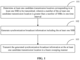
- Fig. 1 is a flow chart showing a method for transmitting a synchronization broadcast transmission according to an exemplary embodiment.
- the method for transmitting a synchronization broadcast transmission is applied to a network access device such as a base station. As shown in Fig. 1 , the method includes the following Step 101 to Step 103.
- Step 101 a candidate transmission location corresponding to an SSB to be transmitted is determined, wherein a number of candidate transmission locations is greater than a number of SSBs in one time interval.
- Step 102 synchronization broadcast transmission including the SSB is generated.
- Step 103 the generated synchronization broadcast transmission is transmitted at the candidate transmission location in a beam sweeping manner.
- the number of SSBs in one time interval is pre-configured by a system according to a frequency band, and is the maximum number of SSBs that may be transmitted in one time interval.
- the number of the candidate transmission locations is also pre-configured by the system, and is a maximum number of candidate transmission locations in one time interval.
- the number of the candidate transmission locations is no greater than the number of SSBs in one time interval.
- the number of the candidate transmission locations is greater than the number of SSBs in one time interval. More candidate transmission locations are provided, and a larger number of beams carrying synchronization broadcast transmission in more possible directions are also provided.
- the base station may have a relatively larger number of other candidate transmission locations for transmission of the synchronization broadcast transmission. Therefore, there are more opportunities for the base station to transmit the synchronization broadcast transmission in one time interval, which is favorable for UE to timely find the synchronization broadcast transmission for synchronization processing.
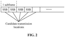
- the number of SSBs in one time interval is 4 (namely L is equal to 4), that is, at most four SSBs are transmitted in one time interval. At most two SSBs are transmitted in a subframe.
- the number of the candidate transmission locations is greater than the number of SSBs in one time interval. That is, When L is equal to 4, the number of the candidate transmission locations is at least equal to 5. When L is equal to 8, the number of the candidate transmission locations is at least equal to 9.
- L may also be 64 and the like. The principle is the same as the above and will not be elaborated herein.
- the number of the candidate transmission locations may be determined according to a configuration of the number of SSBs in one time interval.
- a subframe and a location in the subframe corresponding to each candidate transmission location may be configured flexibly, and the locations may be discontinuous or may be continuous.
- the base station may notify the UE of all configured candidate transmission locations and corresponding subframes as well as corresponding half frames in advance.
- the base station firstly determines an SSB identifier of the SSB to be transmitted, then determines the candidate transmission location corresponding to the SSB identifier, and then transmits the generated synchronization broadcast transmission at the candidate transmission location in a beam sweeping manner.
- the number of the candidate transmission locations is n times the number of SSBs in one time interval, n is equal to 2 or n is a ratio of a duration of a time interval to a duration of a half frame.
- the number of the candidate transmission locations is an integral multiple of SSBs in one time interval, which facilitates the base station to manage and control the candidate transmission locations, conveniently set SSB identifier, and notify the UE of a correspondence relationship between an SSB identifier and a subframe number, and facilitates the UE to recognize the SSB identifier.
- n is a ratio of a duration of a time interval to a duration of a half frame. If the duration of the time interval is 20ms and the duration of the half frame is 5ms, n is equal to 4.
- the number of the candidate transmission locations is 16.
- the number of the candidate transmission locations is 32. That is, the candidate transmission locations may be configured in four half frames, more candidate transmission locations are provided in one time interval, and the candidate transmission locations are distributed in multiple half frames. Even if a half frame is missed, the SSB may also be transmitted in other half frames in one time interval, and there are more options and transmission opportunities.
- the synchronization broadcast transmission further includes an SSB identifier of the SSB; and the SSB identifier is carried in the SSB.
- a maximum value of the SSB identifier corresponds to the number of SSBs in one time interval.
- the maximum value of the SSB identifier corresponds to the number of the candidate transmission locations.
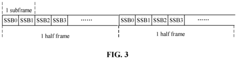
- n 2 as an example, when L is equal to 4, the number of the candidate transmission locations is 8, which correspond to 8 SSBs.
- the maximum value of the SSB identifiers is 3, and the SSBs are numbered from 0 to be SS0, SS1, SSB2 and SSB3.
- the number of the candidate transmission locations is 8, and thus there are two groups of SSB0, SSB1, SSB2 and SSB3, as shown in Fig. 3 .
- the two groups of SSBs may be in the same half frame, or the two groups of SSBs may be in two half frames respectively, one group of SSBs are in in one half frame.
- the half frames and the subframes in the half frames, which are determined as candidate transmission locations, may be configured flexibly.
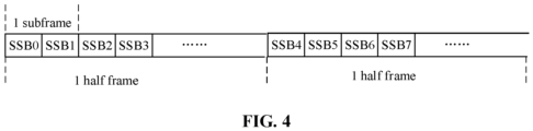
- the maximum value of the SSB identifiers corresponds to the number of the candidate transmission locations.
- the maximum value of the SSB identifiers is 7, and the SSBs are numbered from 0 to be SS0, SS1, ising, SSB6 and SSB7.
- the SSBs are numbered from 0 to be SS0, SS1, ??, SSB6 and SSB7.
- the corresponding SSB identifier is transmitted at the candidate transmission location, and is unrelated to previously transmitted SSB identifier.
- the SSB identifier is transmitted through both a DMRS sequence of a PBCH and data bits in the PBCH in the SSB.
- the maximum value of the SSB identifiers corresponds to the number of the candidate transmission locations.
- L the number of the candidate transmission locations is 8
- the maximum value of the SSB identifiers is 7, and the SSB identifier occupies three bits.
- L the number of the candidate transmission locations is 16
- the maximum value of the SSB identifiers is 15, and the SSB identifier occupies four bits.
- L is equal to 64
- the number of the candidate transmission locations is 128, the maximum value of the SSB identifiers is 127, and the SSB identifier occupies six bits.
- the SSB identifier is transmitted by use of both the DMRS sequence of the PBCH and the data bits in the PBCH.
- the SSB identifier may occupy lower three bits in the DMRS sequence of the PBCH and three data bits in the PBCH.
- the base station transmits the subframe where the SSB is actually transmitted and an SSB identifier in the subframe to the UE in Remaining Minimum System Information (RMSI).
- RMSI Remaining Minimum System Information
- S 103 includes Step A.
- Step A the generated synchronization broadcast transmission is transmitted at the candidate transmission location in a selected candidate transmitting slot in the beam sweeping manner.
- a candidate set of the candidate transmitting slot is ⁇ 10, 20, 40, 80, 160 ⁇ ms.
- a candidate set of the candidate transmitting slot is ⁇ 5, 10, 20, 40, 80, 160 ⁇ ms when the number of SSBs in one time interval is 4, and the candidate set of the candidate transmitting slot is ⁇ 10, 20, 40, 80, 160 ⁇ ms when the number of SSBs in one time interval is greater than 4.
- the number of the candidate transmission locations is increased, and multiple candidate transmission locations may correspond to multiple subframes. Taking that the duration of the half frame is 5ms as an example, when L is equal to 8 and n is equal to 2, the number of the candidate transmission locations is 16, at least corresponding to 8 subframes and two half frames. If the candidate transmitting slot is 5ms, and another candidate transmitting slot is reached at 10ms, the requirement of two half frames may not be met. Therefore, in the embodiment, a candidate set of the candidate transmitting slot is ⁇ 10, 20, 40, 80, 160 ⁇ ms when L is equal to 4, 8, 64 and n is at least 2.
- a candidate set of the candidate transmitting slot is ⁇ 5, 10, 20, 40, 80, 160 ⁇ ms when the number of SSBs in one time interval is 4, and a candidate set of the candidate transmitting slot is ⁇ 10, 20, 40, 80, 160 ⁇ ms when the number of SSBs in one time interval is greater than 4.
- the method further includes Step B1 and Step B2.
- Step B 1 whether a candidate transmission location is idle or not is detected.
- Step B2 when it is detected that the candidate transmission location is not idle, transmission of the generated synchronization broadcast transmission at the candidate transmission location in the beam sweeping manner is waived. A next candidate transmission location is determined, which is equivalent to Step 101.
- Step 102 is continued.
- the base station after selecting a candidate transmission location, detects whether the candidate transmission location is idle or not. If YES, the candidate transmission location may be adopted to transmit the SSB. If NO, another candidate transmission location is required to be selected.
- the reselected candidate transmission location may be a next candidate transmission location adjacent to the candidate transmission location or may be a candidate transmission location spaced from the candidate transmission location by L candidate transmission locations. For example, when a presently selected candidate transmission location corresponds to an SSB0 and the presently selected candidate transmission location is not idle, transmission of the SSB0 is waived, and candidate transmission location corresponding to an SSB1 is selected or a candidate transmission location corresponding to SSB0+L is selected.
- the SSB0 and the SSB2 are expected to be transmitted, and if the candidate transmission location corresponding to the SSB0 is not idle, the SSB1 and the SSB2 are transmitted instead, or the SSB2 and SSB0+L are transmitted instead.
- At least two SSBs to be transmitted belong to a group.
- the method further includes Step B 1, Step B3 and Step B4.
- Step B whether the candidate transmission location is idle or not is detected.
- Step B3 when the candidate transmission location is not idle, all SSBs in a group to which the SSB to be transmitted belongs are determined.
- Step B4 transmission of the generated synchronization broadcast transmission at candidate transmission locations corresponding to all the SSBs in the group in the beam sweeping manner is waived.
- a next SSB to be transmitted in the group is determined, and whether a candidate transmission location corresponding to the next SSB is idle or not is detected.
- the synchronization broadcast transmission is transmitted at the corresponding candidate transmission locations in the beam sweeping manner.
- multiple SSBs are classified into a group in advance.
- the SSB1 and the SSB2 belong to a group.
- An SSB presently to be transmitted is the SSB1.
- the candidate transmission location corresponding to the SSB1 is idle or not is detected, and if NO, it is determined that a group where the SSB1 is located further includes the SSB2, the candidate transmission location corresponding to the SSB2 is determined, and transmission of the generated synchronization broadcast transmission at the candidate transmission locations corresponding to the SSB1 and the SSB2 in the beam sweeping manner are waived.
- the base station may also transmit the SSB1 and the SSB2 or transmit other SSBs at other candidate transmission locations.
- the SSB group is proposed, and multiple SSBs are classified into a group. All the SSBs in a group are managed and controlled in a unified manner, and their transmissions are performed in the unified manner or waived in the unified manner, so that convenience is brought to centralized management of the SSBs.
- Fig. 5 is a flow chart showing a method for transmitting a synchronization broadcast transmission according to an exemplary embodiment.
- the method for transmitting a synchronization broadcast transmission is applied to a network access device such as a base station. As shown in Fig. 5 , the method includes the following Step 501 to Step 502.
- Step 501 a candidate transmission location corresponding to an SSB to be transmitted is determined, wherein a number of candidate transmission locations is greater than a number of SSBs in one time interval.
- Step 502 it is detected whether the candidate transmission location is idle or not, and when it is detected that the candidate transmission locations is not idle, transmission of generated synchronization broadcast transmission at the candidate transmission location in a beam sweeping manner is waived.
- a next candidate transmission location is determined, which is equivalent to Step 501.
- Step 503 is performed.
- Step 503 the synchronization broadcast transmission including the SSB is generated.
- Step 504 the generated synchronization broadcast transmission is transmitted at the candidate transmission location in a selected candidate transmitting slot in the beam sweeping manner.
- the implementation process of transmission of the synchronization broadcast transmission at a base station side is introduced above.
- a UE side is required to correspondingly receive the synchronization broadcast transmission and perform synchronization processing.
- An implementation process of the UE side will be introduced below.
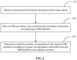
- Fig. 6 is a flow chart showing a method for transmitting a synchronization broadcast transmission according to an exemplary embodiment.
- the method for transmitting a synchronization broadcast transmission is adapted for a network access device such as a base station.
- a terminal may be a mobile phone, a computer, a digital broadcast terminal, a messaging device, a gaming console, a tablet, a medical device, exercise equipment, a personal digital assistant and the like.
- the method includes the following Step 601 to Step 603.
- Step 601 synchronization broadcast transmission from a base station is received.
- Step 602 an SSB is parsed according to the synchronization broadcast transmission, for acquiring an SSB identifier.
- Step 603 a subframe number corresponding to the acquired SSB identifier is determined according to a preset correspondence relationship between SSB identifiers and subframe numbers.
- UE may acquire a subframe where the SSB is located and the SSB identifier in the subframe in advance through RMSI.
- the UE parses the SSB identifier, the corresponding subframe number may be determined, and a beam direction of the SSB identifier may further be determined as a reference for uplink signal transmission to complete synchronization.
- a maximum value of the SSB identifiers corresponds to the number of candidate transmission locations.
- the method further includes Step C1.
- Step C1 the acquired SSB identifier is converted according to a correspondence relationship between the number of the candidate transmission locations and the number of SSBs in one time interval.
- Step 603 includes Step C2.
- Step C2 a subframe number corresponding to the converted SSB identifier is determined.
- SSB identifiers include SSB0, SSB1, whil, SSB6 and SSB7.
- One group of SSBs include SSB0, SSB1, SSB2 and SSB3, and the other group of SSBs include SSB4, SSBS, SSB6 and SSB7.
- the two groups of SSBs are in two half frames respectively.
- a correspondence relationship between SSB identifiers and subframe numbers may be simplified as Table 1.
- Table 1 SSB identifier Subframe number SSB0 Subframe 0 SSB1 Subframe 1 SSB2 Subframe 2 SSB3 Subframe 3
- the UE recognizes that the SSB identifier is SSB6 and converts the acquired SSB identifier according to the correspondence relationship between the number of the candidate transmission locations and the number of SSBs in one time interval.
- n is equal to 2
- SSB6 divided by 2 rounded up, and then minus 1 (since numbering is started from 0) is SSB2. It is determined that a subframe number corresponding to SSB2 is subframe 2.
- Table 1 may also be changed to a correspondence relationship between SSB0, SSB1, ??, SSB6 and SSB7 and subframe numbers, and a correspondence relationship between SSB identifiers and subframe numbers as well as half frame numbers may be added.
- the UE may directly determine the corresponding subframe number according to Table 1 without converting the SSB identifier.
- S602 includes Step D1 to Step D2.
- Step D1 a DMRS sequence of a PBCH in the SSB and data bits in the PBCH are parsed according to the synchronization broadcast transmission.
- Step D2 the SSB identifier is acquired through the DMRS sequence of the PBCH in the SSB and the data bits in the PBCH.
- the UE learns in advance that the SSB identifier is transmitted in the DMRS of the PBCH and the data bits in the PBCH.
- the DMRS sequence of the PBCH carries lower three bits in the SSB identifier, and the data bits in the PBCH carries higher two bits in the SSB identifier.
- Fig. 7 is a flow chart showing a method for transmitting a synchronization broadcast transmission according to an exemplary embodiment.
- the method for transmitting a synchronization broadcast transmission is applied a network access device such as a base station.
- a terminal may be a mobile phone, a computer, a digital broadcast terminal, a messaging device, a gaming console, a tablet, a medical device, exercise equipment, a personal digital assistant and the like.
- the method includes the following Step 701 to Step 703.
- Step 701 synchronization broadcast transmission from a base station is received.
- Step 702 a DMRS sequence of a PBCH in an SSB and a data bits in the PBCH are parsed out according to the synchronization broadcast transmission.
- Step 703 an SSB identifier is acquired through the DMRS sequence of the PBCH in the SSB and the data bits in the PBCH.
- Step 704 the acquired SSB identifier is converted according to a correspondence relationship between the number of candidate transmission locations and the number of SSBs in one time interval.
- Step 705 a subframe number corresponding to the converted SSB identifier is determined according to a preset correspondence relationship between SSB identifiers and subframe numbers.
- the below is a device embodiment of the present disclosure and may be configured to execute the method embodiment of the present disclosure.
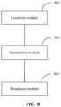
- Fig. 8 is a block diagram of a device for transmitting a synchronization broadcast transmission, according to an exemplary embodiment.
- the device may be implemented as part or whole of an electronic device through software, hardware or a combination of the two.
- the device for transmitting a synchronization broadcast transmission includes a location module 801, a generation module 802 and a broadcast module 803.
- the location module 801 is configured to determine a candidate transmission location corresponding to an SSB to be transmitted, wherein a number of candidate transmission locations is greater than a number of SSBs in one time interval.
- the generation module 802 is configured to generate synchronization broadcast transmission including the SSB.
- the broadcast module 803 is configured to transmit the generated synchronization broadcast transmission at the candidate transmission location in a beam sweeping manner.
- the number of candidate transmission locations is n times the number of SSBs in one time interval, n is equal to 2 or n is a ratio of a duration of a time interval to a duration of a half frame.
- the synchronization broadcast transmission further includes an SSB identifier of the SSB; the SSB identifier is carried in the SSB.
- the maximum value of the SSB identifier corresponds to the number of SSBs in one time interval.
- the maximum value of the SSB identifier corresponds to the number of candidate transmission locations.
- the SSB identifier is transmitted through both a DMRS sequence of a PBCH in the SSB and data bits in the PBCH.
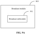
- the broadcast module 803 includes a broadcast submodule 901.
- the broadcast submodule 901 is configured to transmit the generated synchronization broadcast transmission at the candidate transmission location in a selected candidate transmitting slot in the beam sweeping manner.
- a candidate set of the candidate transmitting slot is ⁇ 10, 20, 40, 80, 160 ⁇ ms.
- a candidate set of the candidate transmitting slot is ⁇ 5, 10, 20, 40, 80, 160 ⁇ ms when the number of SSBs in one time interval is 4; and a candidate set of the candidate transmitting slot is ⁇ 10, 20, 40, 80, 160 ⁇ ms when the number of SSBs in one time interval is greater than 4.
- At least two SSBs to be transmitted belong to a group.
- the device further includes a detection module 911, a group module 912 and a waiving module 913.
- the detection module 911 is configured to detect whether the candidate transmission location is idle or not.
- the group module 912 is configured to, when the candidate transmission location is not idle, determine all SSBs in a group to which the SSB to be transmitted belongs.
- the waiving module 913 is configured to waive transmission of the generated synchronization broadcast transmission at candidate transmission locations corresponding to all the SSBs in the group in the beam sweeping manner.
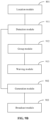
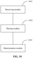
- Fig. 10 is a block diagram of a device for transmitting a synchronization broadcast transmission according to an exemplary embodiment.
- the device may be implemented as a part or whole of an electronic device through software, hardware or a combination of the two.
- the device for transmitting a synchronization broadcast transmission includes a receiving module 1001, a parsing module 1002 and a determination module 1003.
- the receiving module 1001 is configured to receive synchronization broadcast transmission from a base station.
- the parsing module 1002 is configured to parse an SSB according to the synchronization broadcast transmission, for acquiring an SSB identifier.
- the determination module 1003 is configured to determine a subframe number corresponding to the acquired SSB identifier according to a preset correspondence relationship between SSB identifiers and subframe numbers.
- a maximum value of the SSB identifier corresponds to the number of candidate transmission locations.
- the device further includes a conversion module 1101.
- the conversion module 1101 is configured to convert the acquired SSB identifier according to a correspondence relationship between the number of candidate transmission locations and the number of SSBs in one time interval.
- the determination module 1003 includes a determination submodule 1201.
- the determination submodule 1201 is configured to determine a subframe number corresponding to the converted SSB identifier.
- the parsing module 1002 includes a parsing submodule 1301 and an acquisition submodule 1302;
- the parsing submodule 1301 is configured to parse a DMRS sequence of a PBCH in the SSB and data bits in the PBCH according to the synchronization broadcast transmission.
- the acquisition submodule 1302 is configured for acquiring the SSB identifier through the DMRS sequence of the PBCH in the SSB and the data bits in the PBCH.
- Fig. 14 is a block diagram of a device for transmitting synchronization broadcast transmission according to an exemplary embodiment.
- the device 1400 may be a mobile phone, a computer, a digital broadcast terminal, a messaging device, a gaming console, a tablet, a medical device, exercise equipment, a personal digital assistant and the like.
- the device 1400 may include one or more of the following components: a processing component 1402, a memory 1404, a power component 1406, a multimedia component 1408, an audio component 1410, an Input/Output (I/O) interface 1414, a sensor component 1414, and a communication component 1416.
- a processing component 1402 a memory 1404, a power component 1406, a multimedia component 1408, an audio component 1410, an Input/Output (I/O) interface 1414, a sensor component 1414, and a communication component 1416.
- the processing component 1402 typically controls overall operations of the device 1400, such as the operations associated with display, telephone calls, data communications, camera operations, and recording operations.
- the processing component 1402 may include one or more processors 1420 to execute instructions to perform all or part of the steps in the abovementioned method.
- the processing component 1402 may include one or more modules which facilitate interaction between the processing component 1402 and the other components.
- the processing component 1402 may include a multimedia module to facilitate interaction between the multimedia component 1408 and the processing component 1402.
- the memory 1404 is configured to store various types of data to support the operation of the device 1400. Examples of such data include instructions for any applications or methods operated on the device 1400, contact data, phonebook data, messages, pictures, video, etc.
- the memory 1404 may be implemented by any type of volatile or non-volatile memory devices, or a combination thereof, such as a Static Random Access Memory (SRAM), an Electrically Erasable Programmable Read-Only Memory (EEPROM), an Erasable Programmable Read-Only Memory (EPROM), a Programmable Read-Only Memory (PROM), a Read-Only Memory (ROM), a magnetic memory, a flash memory, and a magnetic or optical disk.
- SRAM Static Random Access Memory
- EEPROM Electrically Erasable Programmable Read-Only Memory
- EPROM Erasable Programmable Read-Only Memory
- PROM Programmable Read-Only Memory
- ROM Read-Only Memory
- magnetic memory a magnetic memory
- flash memory and a magnetic or optical disk.
- the power component 1406 provides power for various components of the device 1400.
- the power component 1406 may include a power management system, one or more power supplies, and other components associated with generation, management and distribution of power for the device 1400.
- the multimedia component 1408 includes a screen providing an output interface between the device 1400 and a user.
- the screen may include a Liquid Crystal Display (LCD) and a Touch Panel (TP). If the screen includes the TP, the screen may be implemented as a touch screen to receive an input signal from the user.
- the TP includes one or more touch sensors to sense touches, swipes and gestures on the TP. The touch sensors may not only sense a boundary of a touch or swipe action but also detect a duration and pressure associated with the touch or swipe action.
- the multimedia component 1408 includes a front camera and/or a rear camera.
- the front camera and/or the rear camera may receive external multimedia data when the device 1400 is in an operation mode, such as a photographing mode or a video mode.
- an operation mode such as a photographing mode or a video mode.
- Each of the front camera and the rear camera may be a fixed optical lens system or have focusing and optical zooming capabilities.
- the audio component 1410 is configured to output and/or input an audio signal.
- the audio component 1410 includes a Microphone (MIC), and the MIC is configured to receive an external audio signal when the device 1400 is in the operation mode, such as a call mode, a recording mode and a voice recognition mode.
- the received audio signal may further be stored in the memory 1404 or transmitted through the communication component 1416.
- the audio component 1410 further includes a speaker configured to output the audio signal.
- the I/O interface 1414 provides an interface between the processing component 1402 and a peripheral interface module, and the peripheral interface module may be a keyboard, a click wheel, a button and the like.
- the button may include, but not limited to: a home button, a volume button, a starting button and a locking button.
- the sensor component 1414 includes one or more sensors configured to provide status assessment in various aspects for the device 1400. For instance, the sensor component 1414 may detect an on/off status of the device 1400 and relative locationing of components, such as a display and small keyboard of the device 1400, and the sensor component 1414 may further detect a change in a location of the device 1400 or a component of the device 1400, presence or absence of contact between the user and the device 1400, orientation or acceleration/deceleration of the device 1400 and a change in temperature of the device 1400.
- the sensor component 1414 may include a proximity sensor configured to detect presence of an object nearby without any physical contact.
- the sensor component 1414 may also include a light sensor, such as a Complementary Metal Oxide Semiconductor (CMOS) or Charge Coupled Device (CCD) image sensor, configured for use in an imaging application.
- CMOS Complementary Metal Oxide Semiconductor
- CCD Charge Coupled Device
- the sensor component 1414 may also include an acceleration sensor, a gyroscope sensor, a magnetic sensor, a pressure sensor or a temperature sensor.
- the communication component 1416 is configured to facilitate wired or wireless communication between the device 1400 and another device.
- the device 1400 may access a communication-standard-based wireless network, such as a Wireless Fidelity (WiFi) network, a 2nd-Generation (2G) or 3rd-Generation (3G) network or a combination thereof.
- WiFi Wireless Fidelity
- 2G 2nd-Generation
- 3G 3rd-Generation
- the communication component 1416 receives a broadcast signal or broadcast associated information from an external broadcast management system through a broadcast channel.
- the communication component 1416 further includes a Near Field Communication (NFC) module to facilitate short-range communication.
- NFC Near Field Communication
- the NFC module may be implemented based on a Radio Frequency Identification (RFID) technology, an Infrared Data Association (IrDA) technology, an Ultra-Wide Band (UWB) technology, a Bluetooth (BT) technology and another technology.
- RFID Radio Frequency Identification
- IrDA Infrared Data Association
- UWB Ultra-Wide Band
- BT Bluetooth
- the device 1400 may be implemented by one or more Application Specific Integrated Circuits (ASICs), Digital Signal Processors (DSPs), Digital Signal Processing Devices (DSPDs), Programmable Logic Devices (PLDs), Field Programmable Gate Arrays (FPGAs), controllers, micro-controllers, microprocessors or other electronic components, and is configured to execute the abovementioned method.
- ASICs Application Specific Integrated Circuits
- DSPs Digital Signal Processors
- DSPDs Digital Signal Processing Devices
- PLDs Programmable Logic Devices
- FPGAs Field Programmable Gate Arrays
- controllers micro-controllers, microprocessors or other electronic components, and is configured to execute the abovementioned method.
- a non-transitory computer-readable storage medium including an instruction such as the memory 1404 including an instruction
- the instruction may be executed by the processor 1420 of the device 1400 to implement the abovementioned method.
- the non-transitory computer-readable storage medium may be a ROM, a Random Access Memory (RAM), a Compact Disc Read-Only Memory (CD-ROM), a magnetic tape, a floppy disc, an optical data storage device and the like.
- a device for transmitting a synchronization broadcast transmission which includes:
- the processor may further be configured such that:
- the processor may further be configured to:
- a computer-readable storage medium is provided. Instructions in the storage medium, when executed by the processor of the device, enables the device to execute the method for transmitting a synchronization broadcast transmission, the method includes:
- the instructions in the storage medium may further include that:
- the instructions in the storage medium may further include that: the operation of parsing the SSB according to the synchronization broadcast transmission and the SSB identifier includes:
- Fig. 15 is a block diagram of a device 1500 for data synchronization, according to an exemplary embodiment.
- the device 1500 may be provided as a computer.
- the device 1500 includes a processing component 1522, further including one or more processors, and a memory resource represented by a memory 1532, configured to store instructions executable for the processing component 1522, for example, an application program.
- the application program stored in the memory 1532 may include one or more than one module of which each corresponds to a set of instructions.
- the processing component 1522 is configured to execute the instructions to execute the data synchronization method.
- the device 1500 may further include a power component 1526 configured to execute power management of the device 1500, a wired or wireless network interface 1550 configured to connect the device 1500 to a network and an I/O interface 1558.
- the device 1500 may be operated based on an operating system stored in the memory 1532, for example, Windows ServerTM, Mac OS XTM, UnixTM, LinuxTM, FreeBSDTM or the like.
- a device for transmitting a synchronization broadcast transmission which includes:
- the processor may further be configured such that: the number of the candidate transmission locations is n times the number of SSBs in one time interval, n is equal to 2 or n is a ratio of a duration of a time interval to a duration of a half frame.
- the processor may further be configured such that:
- the processor may further be configured to: transmit the SSB identifier through both a DMRS sequence of a PBCH in the SSB and data bits in the PBCH.
- the processor may further be configured to: in transmitting the generated synchronization broadcast transmission at the candidate transmission location in the beam sweeping manner includes:
- the processor may further be configured such that:
- a computer-readable storage medium is provided. Instructions in the storage medium, when executed by the processor of the device, enable the device to execute the method for transmitting a synchronization broadcast transmission, the method including:
- the instructions in the storage medium may further include that: the number of the candidate transmission locations is n times the number of SSBs in one time interval, n is equal to 2 or n is a ratio of a duration of a time interval to a duration of a half frame.
- the instructions in the storage medium may further include that:
- the instructions in the storage medium may further include that: the SSB identifier is transmitted through a DMRS sequence of a PBCH in the SSB and data bits in the PBCH.
- the instructions in the storage medium may further include that: the operation of transmitting the generated synchronization broadcast transmission at the candidate transmission location in the beam sweeping manner includes:
- the instructions in the storage medium may further include that:
Landscapes
- Engineering & Computer Science (AREA)
- Signal Processing (AREA)
- Computer Networks & Wireless Communication (AREA)
- Computer Security & Cryptography (AREA)
- Databases & Information Systems (AREA)
- Quality & Reliability (AREA)
- Mobile Radio Communication Systems (AREA)
- Circuits Of Receivers In General (AREA)
Priority Applications (1)
| Application Number | Priority Date | Filing Date | Title |
|---|---|---|---|
| EP23156768.6A EP4203375A1 (en) | 2018-04-02 | 2018-04-02 | Method and apparatus for transmitting synchronized broadcast information |
Applications Claiming Priority (3)
| Application Number | Priority Date | Filing Date | Title |
|---|---|---|---|
| EP23156768.6A EP4203375A1 (en) | 2018-04-02 | 2018-04-02 | Method and apparatus for transmitting synchronized broadcast information |
| PCT/CN2018/081524 WO2019191857A1 (zh) | 2018-04-02 | 2018-04-02 | 传输同步广播信息的方法及装置 |
| EP18913219.4A EP3780785B1 (en) | 2018-04-02 | 2018-04-02 | Method and apparatus for transmitting synchronized broadcast information |
Related Parent Applications (2)
| Application Number | Title | Priority Date | Filing Date |
|---|---|---|---|
| EP18913219.4A Division EP3780785B1 (en) | 2018-04-02 | 2018-04-02 | Method and apparatus for transmitting synchronized broadcast information |
| EP18913219.4A Division-Into EP3780785B1 (en) | 2018-04-02 | 2018-04-02 | Method and apparatus for transmitting synchronized broadcast information |
Publications (1)
| Publication Number | Publication Date |
|---|---|
| EP4203375A1 true EP4203375A1 (en) | 2023-06-28 |
Family
ID=63343585
Family Applications (2)
| Application Number | Title | Priority Date | Filing Date |
|---|---|---|---|
| EP18913219.4A Active EP3780785B1 (en) | 2018-04-02 | 2018-04-02 | Method and apparatus for transmitting synchronized broadcast information |
| EP23156768.6A Pending EP4203375A1 (en) | 2018-04-02 | 2018-04-02 | Method and apparatus for transmitting synchronized broadcast information |
Family Applications Before (1)
| Application Number | Title | Priority Date | Filing Date |
|---|---|---|---|
| EP18913219.4A Active EP3780785B1 (en) | 2018-04-02 | 2018-04-02 | Method and apparatus for transmitting synchronized broadcast information |
Country Status (11)
| Country | Link |
|---|---|
| US (2) | US11617142B2 (es) |
| EP (2) | EP3780785B1 (es) |
| JP (1) | JP7089051B2 (es) |
| KR (2) | KR20200132960A (es) |
| CN (2) | CN108496321B (es) |
| BR (1) | BR112020020233A2 (es) |
| ES (1) | ES2946238T3 (es) |
| PL (1) | PL3780785T3 (es) |
| RU (1) | RU2758286C1 (es) |
| SG (1) | SG11202009721WA (es) |
| WO (1) | WO2019191857A1 (es) |
Families Citing this family (11)
| Publication number | Priority date | Publication date | Assignee | Title |
|---|---|---|---|---|
| CN109496438B (zh) * | 2018-09-27 | 2022-06-24 | 北京小米移动软件有限公司 | 传输同步指示信息的方法及装置 |
| WO2020062136A1 (en) * | 2018-09-29 | 2020-04-02 | Lenovo (Beijing) Limited | Candidate synchronization signal block transmission resources |
| WO2020087524A1 (zh) * | 2018-11-02 | 2020-05-07 | Oppo广东移动通信有限公司 | 非授权频段上ssb的传输方法和设备 |
| JP7137705B2 (ja) | 2018-11-15 | 2022-09-14 | ペキン シャオミ モバイル ソフトウェア カンパニー, リミテッド | 同期信号ブロックの構成情報のブロードキャスト、受信方法及び装置 |
| CN111245537B (zh) * | 2018-11-29 | 2021-06-01 | 华为技术有限公司 | 一种测量方法及装置 |
| CN112369093B (zh) * | 2018-11-30 | 2023-09-12 | Oppo广东移动通信有限公司 | 同步信号块ssb传输方式的确定方法、设备、芯片和介质 |
| US11109375B2 (en) | 2018-12-17 | 2021-08-31 | Samsung Electronics Co., Ltd. | Method and apparatus for configuration of common search space for discovery signal and channel |
| WO2020164142A1 (zh) | 2019-02-15 | 2020-08-20 | Oppo广东移动通信有限公司 | 同步信号块信息处理方法、装置及通信装置 |
| CN111901807A (zh) * | 2019-05-06 | 2020-11-06 | 普天信息技术有限公司 | 非授权频谱上的同步信号传输方法和装置 |
| CN112105078B (zh) * | 2019-06-18 | 2023-05-02 | 大唐联仪科技有限公司 | 一种终端信号的数据同步处理方法及装置 |
| CN110649943B (zh) * | 2019-09-20 | 2021-04-20 | 西安交通大学 | 一种通过多个子波束叠加设计波束宽度的波束扫描方法 |
Family Cites Families (17)
| Publication number | Priority date | Publication date | Assignee | Title |
|---|---|---|---|---|
| CN1324824C (zh) * | 2004-11-19 | 2007-07-04 | 中兴通讯股份有限公司 | 多时隙通信系统中终端同步控制命令的映射方法 |
| US8139580B2 (en) * | 2008-02-27 | 2012-03-20 | Industrial Technology Research Institute | System and method for providing multicast and broadcast services |
| CN102201905B (zh) * | 2010-03-23 | 2014-06-25 | 卓胜微电子(上海)有限公司 | Dtmb系统中32qam及4qam-nr的ldpc数据块的同步方法 |
| US8599826B2 (en) * | 2010-04-15 | 2013-12-03 | Motorola Solutions, Inc. | Method for synchronizing direct mode time division multiple access (TDMA) transmissions |
| WO2014043922A1 (zh) * | 2012-09-24 | 2014-03-27 | 华为技术有限公司 | 传输广播消息的方法、基站和用户设备 |
| EP3664353B1 (en) * | 2013-02-06 | 2022-05-04 | LG Electronics Inc. | Method for receiving signal and apparatus for same |
| WO2015174438A1 (ja) * | 2014-05-15 | 2015-11-19 | 株式会社Nttドコモ | ユーザ端末、無線基地局、無線通信方法及び無線通信システム |
| WO2016163842A1 (ko) * | 2015-04-10 | 2016-10-13 | 엘지전자 (주) | 무선 통신 시스템에서 채널 상태 정보를 보고하기 위한 방법 및 이를 위한 장치 |
| WO2016203290A1 (en) * | 2015-06-15 | 2016-12-22 | Telefonaktiebolaget Lm Ericsson (Publ) | Variable synchronization block format |
| CN106453182B (zh) * | 2015-08-07 | 2020-06-09 | 中兴通讯股份有限公司 | 前导发送方法和装置 |
| CN111030794A (zh) * | 2015-12-03 | 2020-04-17 | 华为技术有限公司 | 一种数据的传输方法和基站以及用户设备 |
| CN106793058B (zh) * | 2016-12-30 | 2019-03-05 | 展讯通信(上海)有限公司 | 处理同步信号块的方法、基站及用户设备 |
| CN107278383B (zh) * | 2017-03-28 | 2020-08-14 | 北京小米移动软件有限公司 | 传输、获取同步信息块的方法及装置 |
| CN107528682B (zh) * | 2017-09-20 | 2020-12-22 | 宇龙计算机通信科技(深圳)有限公司 | 参考信号的发送方法及装置 |
| EP3711396B1 (en) * | 2017-11-17 | 2024-07-24 | Panasonic Intellectual Property Corporation of America | Schemes for ssb to paging coreset mapping in nr |
| CN110365438B (zh) * | 2018-03-26 | 2021-05-11 | 华为技术有限公司 | 信号传输方法、相关设备及系统 |
| RU2748223C1 (ru) | 2018-03-29 | 2021-05-21 | Гуандун Оппо Мобайл Телекоммьюникейшнз Корп., Лтд. | Способ передачи сигнала, сетевое устройство и терминал |
-
2018
- 2018-04-02 BR BR112020020233A patent/BR112020020233A2/pt unknown
- 2018-04-02 SG SG11202009721WA patent/SG11202009721WA/en unknown
- 2018-04-02 RU RU2020135501A patent/RU2758286C1/ru active
- 2018-04-02 CN CN201880000501.6A patent/CN108496321B/zh active Active
- 2018-04-02 CN CN202110092663.0A patent/CN112867098B/zh active Active
- 2018-04-02 EP EP18913219.4A patent/EP3780785B1/en active Active
- 2018-04-02 JP JP2020552860A patent/JP7089051B2/ja active Active
- 2018-04-02 KR KR1020207029754A patent/KR20200132960A/ko not_active IP Right Cessation
- 2018-04-02 ES ES18913219T patent/ES2946238T3/es active Active
- 2018-04-02 KR KR1020227007780A patent/KR20220038801A/ko not_active Application Discontinuation
- 2018-04-02 PL PL18913219.4T patent/PL3780785T3/pl unknown
- 2018-04-02 EP EP23156768.6A patent/EP4203375A1/en active Pending
- 2018-04-02 WO PCT/CN2018/081524 patent/WO2019191857A1/zh unknown
-
2020
- 2020-09-28 US US17/034,978 patent/US11617142B2/en active Active
-
2023
- 2023-02-10 US US18/167,549 patent/US12004103B2/en active Active
Non-Patent Citations (3)
| Title |
|---|
| CATT: "Transmitted SS-block Indication", vol. RAN WG1, no. Prague, Czechia; 20170821 - 20170825, 20 August 2017 (2017-08-20), XP051315165, Retrieved from the Internet <URL:http://www.3gpp.org/ftp/Meetings_3GPP_SYNC/RAN1/Docs/> [retrieved on 20170820] * |
| NOKIA ET AL: "On SS Burst Set composition", vol. RAN WG1, no. Qingdao, P.R. China; 20170515 - 20170519, 16 June 2017 (2017-06-16), XP051304430, Retrieved from the Internet <URL:http://www.3gpp.org/ftp/tsg_ran/WG1_RL1/TSGR1_AH/NR_AH_1706/Docs/> [retrieved on 20170616] * |
| NTT DOCOMO ET AL: "Remaining details on Remaining minimum system information delivery", vol. RAN WG1, no. Reno, USA; 20171127 - 20171201, 18 November 2017 (2017-11-18), XP051370220, Retrieved from the Internet <URL:http://www.3gpp.org/ftp/tsg%5Fran/WG1%5FRL1/TSGR1%5F91/Docs/> [retrieved on 20171118] * |
Also Published As
| Publication number | Publication date |
|---|---|
| RU2758286C1 (ru) | 2021-10-28 |
| US12004103B2 (en) | 2024-06-04 |
| CN112867098A (zh) | 2021-05-28 |
| ES2946238T3 (es) | 2023-07-14 |
| CN108496321A (zh) | 2018-09-04 |
| JP2021517429A (ja) | 2021-07-15 |
| PL3780785T3 (pl) | 2023-07-24 |
| WO2019191857A1 (zh) | 2019-10-10 |
| CN112867098B (zh) | 2023-07-18 |
| US11617142B2 (en) | 2023-03-28 |
| KR20200132960A (ko) | 2020-11-25 |
| US20210014807A1 (en) | 2021-01-14 |
| JP7089051B2 (ja) | 2022-06-21 |
| EP3780785A1 (en) | 2021-02-17 |
| EP3780785B1 (en) | 2023-05-31 |
| EP3780785A4 (en) | 2021-04-07 |
| US20230189174A1 (en) | 2023-06-15 |
| KR20220038801A (ko) | 2022-03-29 |
| CN108496321B (zh) | 2020-12-04 |
| SG11202009721WA (en) | 2020-10-29 |
| BR112020020233A2 (pt) | 2021-11-09 |
Similar Documents
| Publication | Publication Date | Title |
|---|---|---|
| US12004103B2 (en) | Method and apparatus for transmitting synchronized broadcast transmission | |
| EP3537792B1 (en) | Signal reception method and apparatus | |
| EP3481107A1 (en) | System information transmission method and device | |
| EP3911066B1 (en) | Methods and devices for configuring, sending and receiving discovery reference signal (drs) | |
| CN109644326A (zh) | 传输随机接入指示信息的方法及装置 | |
| US20230254818A1 (en) | Resource allocation method and resource allocation apparatus | |
| US11206627B2 (en) | System information transmission method and device | |
| US11910334B2 (en) | Method and device for transmitting synchronization indication information | |
| EP3522596B1 (en) | Communication method and device | |
| US11012958B2 (en) | Signal transmission method and signal transmission apparatus | |
| US11310694B2 (en) | Method and device for receiving downlink data during RRC inactive state | |
| US11291035B2 (en) | Information transmitting method and apparatus, base station, and user equipment | |
| CN108781425B (zh) | 传输同步信号的方法及装置 | |
| US20220295461A1 (en) | Downlink control channel receiving and transmitting method and device | |
| EP3562177A1 (en) | System information transmission method and device | |
| US12022513B2 (en) | Method and device for random access | |
| US12041562B2 (en) | Method and device for transmitting synchronization indication information | |
| EP3734897A1 (en) | Data transmission method, device, and system |
Legal Events
| Date | Code | Title | Description |
|---|---|---|---|
| PUAI | Public reference made under article 153(3) epc to a published international application that has entered the european phase |
Free format text: ORIGINAL CODE: 0009012 |
|
| STAA | Information on the status of an ep patent application or granted ep patent |
Free format text: STATUS: REQUEST FOR EXAMINATION WAS MADE |
|
| 17P | Request for examination filed |
Effective date: 20230215 |
|
| AC | Divisional application: reference to earlier application |
Ref document number: 3780785 Country of ref document: EP Kind code of ref document: P |
|
| AK | Designated contracting states |
Kind code of ref document: A1 Designated state(s): AL AT BE BG CH CY CZ DE DK EE ES FI FR GB GR HR HU IE IS IT LI LT LU LV MC MK MT NL NO PL PT RO RS SE SI SK SM TR |