EP4203295B1 - Elektromotor für eine stellende oder fördernde vorrichtung eines kraftfahrzeugs - Google Patents
Elektromotor für eine stellende oder fördernde vorrichtung eines kraftfahrzeugs Download PDFInfo
- Publication number
- EP4203295B1 EP4203295B1 EP22215112.8A EP22215112A EP4203295B1 EP 4203295 B1 EP4203295 B1 EP 4203295B1 EP 22215112 A EP22215112 A EP 22215112A EP 4203295 B1 EP4203295 B1 EP 4203295B1
- Authority
- EP
- European Patent Office
- Prior art keywords
- rotor
- winding
- electric motor
- stator
- axis
- Prior art date
- Legal status (The legal status is an assumption and is not a legal conclusion. Google has not performed a legal analysis and makes no representation as to the accuracy of the status listed.)
- Active
Links
Images


Classifications
-
- H—ELECTRICITY
- H02—GENERATION; CONVERSION OR DISTRIBUTION OF ELECTRIC POWER
- H02P—CONTROL OR REGULATION OF ELECTRIC MOTORS, ELECTRIC GENERATORS OR DYNAMO-ELECTRIC CONVERTERS; CONTROLLING TRANSFORMERS, REACTORS OR CHOKE COILS
- H02P25/00—Arrangements or methods for the control of AC motors characterised by the kind of AC motor or by structural details
- H02P25/16—Arrangements or methods for the control of AC motors characterised by the kind of AC motor or by structural details characterised by the circuit arrangement or by the kind of wiring
- H02P25/22—Multiple windings; Windings for more than three phases
-
- H—ELECTRICITY
- H02—GENERATION; CONVERSION OR DISTRIBUTION OF ELECTRIC POWER
- H02K—DYNAMO-ELECTRIC MACHINES
- H02K1/00—Details of the magnetic circuit
- H02K1/06—Details of the magnetic circuit characterised by the shape, form or construction
- H02K1/12—Stationary parts of the magnetic circuit
- H02K1/14—Stator cores with salient poles
- H02K1/145—Stator cores with salient poles having an annular coil, e.g. of the claw-pole type
-
- H—ELECTRICITY
- H02—GENERATION; CONVERSION OR DISTRIBUTION OF ELECTRIC POWER
- H02K—DYNAMO-ELECTRIC MACHINES
- H02K29/00—Motors or generators having non-mechanical commutating devices, e.g. discharge tubes or semiconductor devices
- H02K29/06—Motors or generators having non-mechanical commutating devices, e.g. discharge tubes or semiconductor devices with position sensing devices
- H02K29/08—Motors or generators having non-mechanical commutating devices, e.g. discharge tubes or semiconductor devices with position sensing devices using magnetic effect devices, e.g. Hall-plates, magneto-resistors
-
- H—ELECTRICITY
- H02—GENERATION; CONVERSION OR DISTRIBUTION OF ELECTRIC POWER
- H02P—CONTROL OR REGULATION OF ELECTRIC MOTORS, ELECTRIC GENERATORS OR DYNAMO-ELECTRIC CONVERTERS; CONTROLLING TRANSFORMERS, REACTORS OR CHOKE COILS
- H02P6/00—Arrangements for controlling synchronous motors or other dynamo-electric motors using electronic commutation dependent on the rotor position; Electronic commutators therefor
- H02P6/14—Electronic commutators
- H02P6/16—Circuit arrangements for detecting position
-
- G—PHYSICS
- G01—MEASURING; TESTING
- G01D—MEASURING NOT SPECIALLY ADAPTED FOR A SPECIFIC VARIABLE; ARRANGEMENTS FOR MEASURING TWO OR MORE VARIABLES NOT COVERED IN A SINGLE OTHER SUBCLASS; TARIFF METERING APPARATUS; MEASURING OR TESTING NOT OTHERWISE PROVIDED FOR
- G01D5/00—Mechanical means for transferring the output of a sensing member; Means for converting the output of a sensing member to another variable where the form or nature of the sensing member does not constrain the means for converting; Transducers not specially adapted for a specific variable
- G01D5/12—Mechanical means for transferring the output of a sensing member; Means for converting the output of a sensing member to another variable where the form or nature of the sensing member does not constrain the means for converting; Transducers not specially adapted for a specific variable using electric or magnetic means
- G01D5/14—Mechanical means for transferring the output of a sensing member; Means for converting the output of a sensing member to another variable where the form or nature of the sensing member does not constrain the means for converting; Transducers not specially adapted for a specific variable using electric or magnetic means influencing the magnitude of a current or voltage
- G01D5/142—Mechanical means for transferring the output of a sensing member; Means for converting the output of a sensing member to another variable where the form or nature of the sensing member does not constrain the means for converting; Transducers not specially adapted for a specific variable using electric or magnetic means influencing the magnitude of a current or voltage using Hall-effect devices
- G01D5/145—Mechanical means for transferring the output of a sensing member; Means for converting the output of a sensing member to another variable where the form or nature of the sensing member does not constrain the means for converting; Transducers not specially adapted for a specific variable using electric or magnetic means influencing the magnitude of a current or voltage using Hall-effect devices influenced by the relative movement between the Hall device and magnetic fields
-
- H—ELECTRICITY
- H02—GENERATION; CONVERSION OR DISTRIBUTION OF ELECTRIC POWER
- H02K—DYNAMO-ELECTRIC MACHINES
- H02K2201/00—Specific aspects not provided for in the other groups of this subclass relating to the magnetic circuits
- H02K2201/06—Magnetic cores, or permanent magnets characterised by their skew
-
- H—ELECTRICITY
- H02—GENERATION; CONVERSION OR DISTRIBUTION OF ELECTRIC POWER
- H02P—CONTROL OR REGULATION OF ELECTRIC MOTORS, ELECTRIC GENERATORS OR DYNAMO-ELECTRIC CONVERTERS; CONTROLLING TRANSFORMERS, REACTORS OR CHOKE COILS
- H02P8/00—Arrangements for controlling dynamo-electric motors rotating step by step
- H02P8/12—Control or stabilisation of current
Definitions
- the invention relates to an electric motor for a positioning or conveying device of a motor vehicle, comprising a stator with a first winding and a second winding, wherein the second winding and the first winding can be controlled independently of one another, in particular with a phase shift, a rotor which magnetically interacts with the magnetic fields generated by energizing the windings, and a sensor device for detecting a position of the rotor.
- Such electric motors for actuating or conveying devices are known in the art in a wide variety of designs. Such devices include, in particular, different valves, wherein the electric motor allows a valve body to be adjusted stepwise or continuously between different positions.
- expansion valves which serve to reduce the pressure of a working fluid by throttling the available flow cross-section, which can be varied by the valve body, and to increase the volume of the working fluid, i.e., to expand it.
- expansion valves which serve to reduce the pressure of a working fluid by throttling the available flow cross-section, which can be varied by the valve body, and to increase the volume of the working fluid, i.e., to expand it.
- a conveying device is understood to mean, in particular, pumps or compressors, wherein the electric motor, in contrast to actuating devices, which move to different positions, serves to continuously drive a pump or compressor rotor, whereby a fluid is continuously conveyed.
- an electric motor for positioning or conveying devices has a stator with two windings. When the windings are energized, a magnetic field is generated in different directions depending on the current direction of the energized windings. The magnetic field generated by the energization of the windings interacts with a magnetized rotor, thereby driving the rotor and causing it to rotate around an axial axis.
- Electric motors also differ in the type of commutation.
- Brushless motors are further differentiated between sensorless and sensor-controlled commutation.
- Electric motors with sensor-controlled commutation typically include a sensor device with multiple Hall sensors for detecting the rotor position by sensing the rotor's magnetic field. The stator windings are controlled via appropriate control electronics based on the rotor position.
- sensor-controlled commutation is that the electric motor can be operated even at very low speeds or while stationary.
- Such an electric motor is used, for example, in the DE 10 2015 106 890 A1
- the electric motor is designed as a two-phase stepper motor, wherein the two phases are controlled with a phase shift of 90° to one another.
- the electric motor further comprises either a sensor device with a single Hall sensor, wherein a second output signal is derived from a first output signal by differentiation, or two Hall sensors, each with an output signal.
- the two output signals are used for the phase-shifted control of the two windings.
- the disadvantage of the first embodiment i.e. with a single Hall sensor, is that the determination of the second output signal is complex and only upon a movement, in particular a rotation, of a signal connected to the Hall sensor interacting magnetic field. This makes the first design particularly unsuitable for positioning devices where the rotor speed is relatively low.
- the second design, with two Hall sensors has the disadvantage that adequate space must be available for both Hall sensors. Furthermore, the two Hall sensors increase the cost and assembly effort of the electric motor.
- JP 2015 114208 A and from DE 10 2020 112 658 A1 An electric motor with a two-phase stator is known, whereby the rotational angle position of the rotor required for controlling the stator is determined by a multi-axis Hall sensor.
- the stator is designed as a claw-pole stator.
- the US 2017/244345 A1 an actuator for a flap or for a valve for adjusting a gaseous or liquid volume flow is known, wherein the actuator has a brushless two-phase DC motor and a Hall sensor.
- the task is to provide an electric motor in which the independent or phase-shifted control of the two windings can be carried out in a simple, reliable, space-saving and cost-effective manner.
- the electric motor according to the invention comprises a sensor device with a multi-phase Hall element with two output signals.
- the first output signal is assigned to the first winding, so that the first winding is controlled by the first output signal.
- the second Output signal is assigned to the second winding so that the second winding is controlled by the second output signal.
- the multi-axis Hall element has several axes aligned perpendicular to each other, i.e., 90° to each other.
- the multi-axis Hall element can detect magnetic field lines aligned along the axes and the associated magnetic flux density. In other words, the multi-axis Hall element detects two different components of the magnetic flux density.
- the detected magnetic flux density, and thus the output signals change depending on the rotor position, with the magnetic flux density changing between a maximum and a minimum in each direction, with the maximum and minimum of the first axis being phase-shifted from the maximum and minimum of the second axis.
- the output signals of the multi-axis Hall element are phase-shifted.
- the phase shift of the output signals corresponds to the phase shift required to control the two windings. This allows the output signals of the multi-axis Hall element to be used unchanged, or almost unchanged, to control the two windings. This creates a direct link between the rotor position and the control of the windings.
- the stator is a claw-pole stator, with the claw-pole stator comprising two, preferably identical, claw-pole stator elements arranged axially adjacent to one another, each having a winding and a pair of claw-pole laminations.
- a claw-pole stator, or a claw-pole motor with two claw-pole stator elements is a two-phase electric motor that can be manufactured simply and cost-effectively and is particularly well-suited for low speeds.
- Each pair of claw pole plates comprises two claw pole plates, each comprising a plate-like section and a plurality of claws extending axially from the plate-like section and distributed over the circumference.
- the plate-like sections are arranged at opposite axial ends of the windings, and the claws of the claw pole plates each engage in the free areas between the claws of the opposite claw pole plate.
- the claw pole plates, and in particular the claws are magnetized opposite to one another, with the magnetization depending on the direction of current flow in the winding.
- a first claw-pole stator element is arranged electrically rotated by 90° relative to a second claw-pole stator element. This allows for a two-phase claw-pole motor, whereby the 90° rotation of the claw-pole stator elements requires a 90° phase-shifted control of the two windings, and the required phase-shifted control of the windings can be achieved directly by the output signals of the multi-axis Hall element.
- the control, especially the phase-shifted control, of the two windings can be achieved in a simple, reliable, space-saving, and cost-effective manner. Only one Hall element is required, eliminating the need for complex output signal processing. Furthermore, this allows for fine resolution when detecting the rotor position.
- the magnetic poles associated with the first winding are arranged rotated relative to the magnetic poles associated with the second winding, wherein the phase shift between the two output signals of the multi-axis Hall element is identical to the electrical rotation between the two magnetic poles assigned to the two windings.
- the magnetic poles assigned to the first winding are arranged electrically rotated by 90° relative to the magnetic poles assigned to the second winding. Because the electrical rotation of the magnetic poles assigned to the two windings relative to one another corresponds to the phase shift of the two output signals, a fixed connection can be established between the output signals and the control of the windings.
- the magnetic poles assigned to the first winding are mechanically rotated by an angle of 90°/number of pole pairs relative to the magnetic poles assigned to the second winding.
- the angle is 11.25°, whereby this mechanical rotation corresponds to an electrical rotation of 90° for eight magnetic pole pairs.
- the multi-axis Hall element is a multi-axis Hall switch, wherein the multi-axis Hall switch can be switched to a first switching state when a magnetic field threshold is exceeded and to a second switching state when the magnetic field threshold is exceeded.
- the multi-axis Hall switch detects, for each axis, whether a sufficiently high magnetic flux density is present during rotor rotation.
- the switching states result in a sinusoidal output signal for each axis. Due to the 90° arrangement of the two axes to each other, a sinusoidal first output signal is generated for controlling the first winding and a cosinusoidal second output signal is generated for controlling the second winding. This allows the windings to be controlled in a simple manner with a phase shift depending on the rotor position.
- the rotor has a plurality of permanent magnets or a plurality of permanently magnetized regions, wherein the permanent magnets or the magnetized regions are arranged or designed such that a north pole and a south pole are arranged alternately over an annular cross-section.
- the multi-axis Hall element interacts with the permanent magnets or the magnetized regions of the rotor to detect the angle of rotation of the rotor, the rotor protruding axially from the stator, and the multi-axis Hall element is arranged on a protruding section of the rotor. This allows the permanent magnets or the magnetized regions of the rotor to be used to determine the rotor position, so that no additional sensor magnet is required. The functionality is also maintained with a rotor that is flush with the stator, although the detection of the magnetic field is improved with a rotor that protrudes from the stator.
- the multi-axis Hall element is a two-axis Hall element or a three-axis Hall element.
- a three-axis Hall element only two axes spanning a single plane are used for the two output signals.
- the three-axis Hall element can be arranged in any orientation. The axes aligned in the radial and tangential directions of the rotor are used for the output signals.
- both claw-pole plates of a claw-pole plate pair each have eight claws, and the rotor is designed with 16 poles. This allows for fine resolution in the control and in determining the rotor position.
- the claw-pole stator elements are arranged mechanically rotated relative to one another around an axial axis of the stator by an angle of 11.25°, which results from 90° per magnetic pole pair.
- An electric motor is thus provided for a positioning or conveying device of a motor vehicle, in which the control of the both windings in a simple, reliable, space-saving and cost-effective manner.
- the Figure 1 shows an actuating device 2, in particular for a refrigerant or air conditioning circuit.
- the device 2 comprises an actuator 10 and a multi-part housing 11, wherein the actuator 10 is arranged in the housing 11 and the valve components are arranged on or in the housing 11.
- the actuator 10 comprises an electric motor 12, an electronics unit 58, and a spindle gear 60.
- the electric motor 12 is designed in the form of a permanent magnet synchronous motor, in particular in the form of a claw-pole motor.
- the electric motor 12 has a claw-pole stator 14 with two axially adjacent claw-pole stator elements 16, 18, wherein the two claw-pole stator elements 16, 18 each have a winding 20, 22 and a pair of claw-pole sheets 24, 26.
- the pairs of claw-pole sheets 24, 26 each have two claw-pole sheets 28, 30, 32, 34 and a return plate 31, 33, wherein the claw-pole sheets 28, 30, 32, 34 each have a plate-like section and a plurality of claws 38 extending perpendicularly from the plate-like sections.
- the claws 38 of a Claw pole sheets 28, 30, 32, 34 of a claw pole sheet pair 24, 26 engage in a space between adjacent claws 38 of the other claw pole sheet 28, 30, 32, 34 of the same claw pole sheet pair 24, 26, so that the claws 38 of the claw pole sheets 28, 30, 32, 34 are arranged alternately in the circumferential direction.
- the claw-pole plates 28, 30, 32, 34 of a claw-pole plate pair 24, 26 are magnetized depending on the current direction of the winding 20, 22 and the resulting magnetic field.
- each claw pole plate 28, 30, 32, 34 has eight claws 38, so that each claw pole stator element 16, 18 has 16 poles.
- the claw-pole stator elements 16, 18 are arranged directly next to one another in the axial direction, wherein the magnetic poles of the claw-pole stator elements 16, 18 formed by the claws 38 are arranged mechanically rotated relative to one another by an angle of 11.25° about an axial axis A.
- the rotated arrangement of the claw-pole stator elements 16, 18 is shown in Figure 2 shown.
- a rotation of the claw-pole stator elements 16, 18 by 11.25° corresponds to an electrical rotation of 90° with eight magnetic pole pairs of the claw-pole stator elements 16, 18.
- Such an arrangement of the claw-pole stator elements 16, 18 requires a 90° phase-shifted control of the two windings 20, 22.
- the electric motor 12 further comprises a rotor 40, which is designed with 16 poles and has corresponding magnetized regions.
- the regions are designed such that eight north poles N and eight south poles S are provided, with the south poles S and the north poles N being arranged in
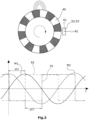
- the arrangement of the magnetized areas of the rotor 40 is shown in Figure 3 shown, with the magnetic field between a north pole and a south pole being shown as an example.
- the electric motor 12 also has a sensor device 50 with a multi-axis Hall element 52.
- the multi-axis Hall element 52 is arranged on the electronics unit 58 and protrudes, as shown in Figure 2 shown, in the direction of the rotor 40.
- the rotor 40 is designed to be longer than the claw-pole stator 14, whereby the multi-axis Hall element 52 can detect the magnetic fields of the rotor 40.
- the rotor 40 can also be designed to be flush with the claw-pole stator 14, whereby the magnetic fields of the rotor 40 can also be detected by the multi-axis Hall element 52.
- a separate permanent magnet could be arranged on the rotor 40, which interacts with the multi-axis Hall element 52.
- the multi-axis Hall element 52 is designed as a two-axis Hall switch 53 and has two output signals S1, S2, with two perpendicular axes A1, A2 each assigned an output signal S1, S2.
- a three-axis Hall switch or sensor can be used, with two axes spanning a plane being assigned to the output signals S1, S2.
- the functionality of the two-axis Hall switch 53 with respect to the output signals S1, S2 is such that a circuit of the two-axis Hall switch 53 switches to a first switching state when a predefined magnetic field threshold is exceeded and to a second switching state when the magnetic field threshold is below.
- a signal corresponding to the magnetization of the rotor 40, in particular a sinusoidal signal, is generated from the detected switching states.
- the Figure 3 shows schematically the arrangement of the two-axis Hall switch 53 on the rotor 40 as well as the curves of the magnetic flux densities M1, M2 in the direction of the two axes A1, A2 and the output signals S1, S2 of the two-axis Hall switch 53 used to control the windings 20, 22.
- the rotor 40 rotates and the two-axis Hall switch 53 detects the magnetic field line aligned in the direction of the axes A1, A2 and the associated magnetic flux density.
- the two-axis Hall switch 53 detects two different components of the magnetic flux density.
- the detected magnetic flux densities M1, M2 change with the rotation of the rotor 40 between a maximum and a minimum, wherein the Figure 3 shown curves of the two magnetic flux densities M1, M2 are phase-shifted by 90°, i.e. n/2, from one another.
- the two-axis Hall switch 53 switches between two switching states, resulting in the two rectangular output signals S1, S2, which are phase-shifted by 90° from one another. Switching between the two switching states occurs when a defined magnetic field threshold value is exceeded or undershot, which is defined in the region of the zero crossing of the curves of the magnetic flux densities S1, S2.
- the phase shift of the output signals S1, S2 corresponds to the phase shift required to control the two windings 20, 22.
- the output signals S1, S2 of the two-axis Hall switch 53 can therefore be used unchanged or almost unchanged to control the two windings 20, 22. This creates a direct link between the position of the rotor 40 and the control of the windings 20, 22.
- the spindle gear 60 has a spindle nut 62 and a spindle rod 64.
- the spindle nut 62 is arranged in a receiving opening 42 provided on the rotor 40 and is firmly connected to the rotor.
- the spindle nut 62 has an internal thread that engages with an external thread of the spindle nut 62.
- a valve body 66 is arranged on the spindle rod 64, which valve body cooperates with a valve seat 68 which is formed on the housing 11 and onto which the valve body 66 is placed when the rotor 40 rotates or from which the valve body 66 is lifted off, so that a precise control of a free flow cross-section between the valve seat 68 and the valve body 66 takes place depending on the rotational position of the rotor 40.
- an electric motor 12 for a positioning or conveying device of a motor vehicle in which the phase-shifted control of the two windings 20, 22 can be carried out in a simple, reliable, space-saving and cost-effective manner.
Landscapes
- Engineering & Computer Science (AREA)
- Power Engineering (AREA)
- Brushless Motors (AREA)
- Control Of Motors That Do Not Use Commutators (AREA)
Description
- Die Erfindung betrifft einen Elektromotor für eine stellende oder fördernde Vorrichtung eines Kraftfahrzeugs, mit einem Stator mit einer ersten Wicklung und einer zweiten Wicklung, wobei die zweite Wicklung und die erste Wicklung unabhängig voneinander, insbesondere phasenverschoben, ansteuerbar sind, einem Rotor, welcher mit den durch eine Bestromung der Wicklungen entstehenden Magnetfeldern magnetisch zusammenwirkt, und einer Sensorvorrichtung zur Erfassung einer Position des Rotors.
- Derartige Elektromotoren für stellende oder fördernde Vorrichtungen sind in unterschiedlichsten Ausführungsformen aus dem Stand der Technik bekannt. Unter derartigen Vorrichtungen sind insbesondere unterschiedliche Ventile zu verstehen, wobei durch den Elektromotor ein Ventilkörper zwischen unterschiedlichen Stellungen stufenartig oder stufenlos verstellbar ist. Ein Beispiel dafür sind Expansionsventile, welche dazu dienen, den Druck eines Arbeitsfluids durch Drosselung des zur Verfügung stehenden und durch den Ventilkörper veränderbaren Durchströmungsquerschnitts zu verringern und das Volumen des Arbeitsfluids zu erhöhen, dieses also zu expandieren. Durch die Verwendung geregelter Expansionsventile kann dabei sowohl der Druckabfall und damit die Volumenzunahme geregelt werden als auch der Fluidstrom nahezu vollständig unterbrochen werden. Unter einer fördernden Vorrichtung sind insbesondere Pumpen bzw. Verdichter zu verstehen, wobei der Elektromotor, im Gegensatz zu stellenden Vorrichtungen, welche unterschiedliche Stellungen anfahren, einem kontinuierlichen Antrieb eines Pumpen- bzw. Verdichterrotors dienen, wodurch ein Fluid kontinuierlich gefördert wird.
- Eine Ausführungsform eines Elektromotors für stellende oder fördernde Vorrichtungen weist einen Stator mit zwei Wicklungen auf, wobei bei einer Bestromung der Wicklungen in Abhängigkeit von der Stromrichtung der bestromten Wicklungen ein Magnetfeld in unterschiedliche Richtungen hervorgerufen wird. Das durch die Bestromung der Wicklungen hervorgerufene Magnetfeld wirkt mit einem magnetisierten Rotor zusammen, wobei der Rotor dadurch angetrieben wird und um eine Axialachse rotiert.
- Weiterhin unterscheiden sich Elektromotoren in der Art der Kommutierung. Bei den bürstenlosen Motoren wird nochmals zwischen sensorloser und sensorgesteuerter Kommutierung unterschieden. Die Elektromotoren mit einer sensorgesteuerten Kommutierung umfassen üblicherweise eine Sensorvorrichtung, welche mehrere Hall-Sensoren zur Erfassung der Rotorposition durch Erfassung eines Magnetfelds des Rotors aufweisen, wobei entsprechend der Rotorposition die Wicklungen des Stators über eine entsprechende Steuerelektronik angesteuert werden. Der entscheidende Vorteil der sensorgesteuerten Kommutierung ist, dass der Elektromotor auch bei sehr geringen Drehzahlen bzw. im Stand betrieben werden kann.
- Ein derartiger Elektromotor ist beispielsweise in der
DE 10 2015 106 890 A1 offenbart. Dabei ist der Elektromotor als ein Zweiphasen-Schrittmotor ausgeführt, wobei die beiden Phasen um 90° phasenverschoben zueinander angesteuert werden. Der Elektromotor weist weiterhin entweder eine Sensorvorrichtung mit einem einzigen Hallsensor, wobei ein zweites Ausgangssignal durch eine Differentiation von einem ersten Ausgangssignal abgeleitet wird, oder zwei Hallsensoren mit jeweils einem Ausgangssignal auf. Die beiden Ausgangssignale werden zur phasenverschobenen Ansteuerung der beiden Wicklungen genutzt. Nachteilig an der ersten Ausführung, d.h. mit einem einzigen Hallsensor, ist, dass die Ermittlung des zweiten Ausgangssignals aufwendig ist und erst bei einer Bewegung, insbesondere einer Drehung, eines mit dem Hallsensor zusammenwirkenden Magnetfelds erfolgen kann. Damit ist die erste Ausführung insbesondere für stellende Vorrichtungen, bei welcher die Drehzahl des Rotors relativ gering ist, eher ungeeignet. Die zweite Ausführungsform, d.h. mit zwei Hallsensoren, hat den Nachteil, dass ein entsprechender Bauraum für die beiden Hallsensoren zur Verfügung stehen muss. Weiterhin erhöhen die beiden Hallsensoren die Kosten und den Montageaufwand des Elektromotors. - Ferner ist aus
JP 2015 114208 A DE 10 2020 112 658 A1 jeweils ein Elektromotor mit einem zweiphasigen Stator bekannt, wobei die für die Ansteuerung des Stators erforderliche Drehwinkelposition des Rotors durch einen mehrachsigen Hall-Sensor ermittelt wird. In der Ausführung derDE 10 2020 112 658 A1 ist der Stator als Klauenpolstator ausgeführt. - Ferner ist aus der
US 2017/244345 A1 ein Stellantrieb für eine Klappe oder für ein Ventil zum Einstellen eines gasförmigen oder flüssigen Volumenstroms bekannt, wobei der Stellantrieb einen bürstenlosen Zweiphasen-Gleichstrommotor und einen Hall-Sensor aufweist. - Es stellt sich die Aufgabe, einen Elektromotor bereitzustellen, bei welchem die voneinander unabhängige bzw. phasenverschobene Ansteuerung der beiden Wicklungen auf eine einfache, zuverlässige, bauraumsparende und kostengünstige Weise erfolgen kann.
- Diese Aufgabe wird durch einen Elektromotor für eine stellende oder fördernde Vorrichtung eines Kraftfahrzeugs mit den Merkmalen des Anspruchs 1 gelöst.
- Der erfindungsgemäße Elektromotor weist eine Sensorvorrichtung mit einem Mehr-Phasen-Hall-Element mit zwei Ausgangssignalen auf. Das erste Ausgangssignal ist der ersten Wicklung zugeordnet, so dass die erste Wicklung durch das erste Ausgangssignal angesteuert wird. Das zweite Ausgangssignal ist der zweiten Wicklung zugeordnet, so dass die zweite Wicklung durch das zweite Ausgangssignal angesteuert wird.
- Das Mehr-Achsen-Hall-Element weist mehrere senkrecht zueinander, d.h. 90° zueinander, ausgerichtete Achsen auf, wobei durch das Mehr-Achsen-Hall-Element in Richtung der Achsen ausgerichtete Magnetfeldlinie und die dazugehörige magnetische Flussdichte erfasst werden können. In anderen Worten erfasst das Mehr-Achsen-Hall-Element zwei verschiedene Komponenten der magnetischen Flussdichte. Dabei verändert sich die erfasste Magnetflussdichte und damit die Ausgangssignale in Abhängigkeit von der Rotorposition, wobei sich die Magnetflussdichte in die jeweilige Richtung zwischen einem Maximum und einem Minimum verändert, wobei das Maximum bzw. das Minimum der ersten Achse zum Maximum bzw. Minimum der zweiten Achse phasenverschoben sind.
- Dadurch, dass die Achsen 90° zueinander ausgerichtet sind, sind die Ausgangssignale des Mehr-Achsen-Hall-Elements phasenverschoben zueinander. Die Phasenverschiebung der Ausgangssignale entspricht der erforderlichen Phasenverschiebung zur Ansteuerung der beiden Wicklungen. Damit können die Ausgangssignale des Mehr-Achsen-Hall-Elements unverändert bzw. nahezu unverändert zur Ansteuerung der beiden Wicklungen genutzt werden. Dadurch besteht eine direkte Verknüpfung zwischen der Rotorposition und der Ansteuerung der Wicklungen.
- Der Stator ist ein Klauenpolstator, wobei der Klauenpolstator zwei, vorzugsweise identische, Klauenpolstatorelemente aufweist, welche axial nebeneinander angeordnet sind und jeweils eine Wicklung und jeweils ein Klauenpolblechpaar aufweisen. Ein Klauenpolstator bzw. ein Klauenpolmotor mit zwei Klauenpolstatorelementen ist ein zweiphasiger Elektromotor, welcher auf eine einfache und kostengünstige Weise hergestellt werden kann und für niedrige Drehzahlen besonders gut geeignet ist.
- Jedes Klauenpolblechpaar weist zwei Klauenpolbleche auf, welche jeweils einen plattenartigen Abschnitt und mehrere von dem plattenartigen Abschnitt, in Axialrichtung erstreckende und über den Umfang verteilte Klauen aufweisen. Im montierten Zustand sind die plattenartigen Abschnitte an entgegengesetzten Axialenden der Wicklungen angeordnet und die Klauen der Klauenpolbleche greifen jeweils in die freien Bereiche zwischen den Klauen des gegenüberliegenden Klauenpolblechs ein. Bei einer Bestromung der Wicklung erfolgt eine Magnetisierung der Klauenpolbleche und insbesondere der Klauen entgegengesetzt zueinander, wobei die Magnetisierung von der Richtung des Stromflusses der Wicklung abhängt.
- Ein erstes Klauenpolstatorelement ist elektrisch um 90° zu einem zweiten Klauenpolstatorelement verdreht angeordnet. Auf diese Weise kann ein zweiphasiger Klauenpolmotor bereitgestellt werden, wobei durch die 90°-Verdrehung der Klauenpolstatorelemente eine um 90°-phasenverschobene Ansteuerung der beiden Wicklungen erforderlich ist, und wobei die erforderliche, phasenverschobene Ansteuerung der Wicklungen direkt durch die Ausgangssignale des Mehr-Achsen-Hall-Elements erfolgen kann.
- Durch die Ausführung des Elektromotors mit einem Mehr-Achsen-Hall-Element kann die Ansteuerung, insbesondere die phasenverschobene Ansteuerung, der beiden Wicklungen auf eine einfache, zuverlässige, bauraumsparende und kostengünstige Weise erfolgen, wobei lediglich ein Hall-Element erforderlich ist und auf eine aufwendige Aufbereitung der Ausgangssignale verzichtet werden kann. Weiterhin kann dadurch eine feine Auflösung bei der Erfassung der Rotorposition bereitgestellt werden.
- Vorzugsweise sind die der ersten Wicklung zugeordnete Magnetpole zu den der zweiten Wicklung zugeordneten Magnetpolen verdreht angeordnet, wobei die Phasenverschiebung zwischen den beiden Ausgangssignalen des Mehr-Achsen-Hall-Elements identisch zu der elektrischen Verdrehung zwischen den beiden, den beiden Wicklung zugeordneten Magnetpolen ist. In einer bevorzugten Ausgestaltung sind die der ersten Wicklung zugeordneten Magnetpole um 90° elektrisch zu den der zweiten Wicklung zugeordneten Magnetpolen verdreht angeordnet. Dadurch, dass die elektrische Verdrehung der den beiden Wicklungen zugeordneten Magnetpole relativ zueinander der Phasenverschiebung der beiden Ausgangssignale entspricht, kann eine feste Verknüpfung zwischen den Ausgangssignalen und der Ansteuerung der Wicklungen hergestellt werden.
- Vorzugsweise sind die der ersten Wicklung zugeordneten Magnetpole um einen Winkel = 90°/Polpaaranzahl zu den der zweiten Wicklung zugeordneten Magnetpolen mechanisch verdreht angeordnet. Bei acht Magnetpolpaaren ist der Winkel 11,25°, wobei diese mechanische Verdrehung bei acht Magnetpolpaaren einer elektrischen Verdrehung von 90° entspricht.
- Vorzugsweise ist das Mehr-Achsen-Hall-Element ein Mehr-Achsen-Hall-Schalter, wobei der Mehr-Achsen-Hall-Schalter bei einer Überschreitung eines Magnetfeld-Schwellenwerts in einen ersten Schaltzustand schaltbar ist und unterhalb des Magnetfeld-Schwellenwerts in einen zweiten Schaltzustand schaltbar ist. In anderen Worten detektiert der Mehr-Achsen-Hall-Schalter bei einer Rotation des Rotors für jede Achse, ob eine ausreichend hohe Magnetflussdichte vorliegt oder nicht. Aus den Schaltzuständen resultiert für jede Achse jeweils ein sinusförmiges Ausgangssignal, wobei aufgrund der 90°-Anordnung der beiden Achsen zueinander ein sinusförmiges, erstes Ausgangssignal für die Ansteuerung der ersten Wicklung und ein cosinusförmiges, zweites Ausgangssignal zur Ansteuerung der zweiten Wicklung hervorgeht. Damit können die Wicklungen auf eine einfache Weise in Abhängigkeit von der Rotorposition phasenverschoben angesteuert werden.
- Vorzugsweise weist der Rotor mehrere Permanentmagnete oder mehrere permanent magnetisierte Bereiche auf, wobei die Permanentmagnete bzw. die magnetisierten Bereiche derart angeordnet oder ausgeführt sind, dass über einen ringförmigen Querschnitt jeweils ein Nordpol und ein Südpol abwechselnd angeordnet sind. In einer bevorzugten Ausgestaltung wirken das Mehr-Achsen-Hall-Element zur Erfassung des Drehwinkels des Rotors mit den Permanentmagneten oder den magnetisierten Bereichen des Rotors zusammen, wobei der Rotor axial aus dem Stator herausragt, wobei an einem herausragenden Abschnitt des Rotors das Mehr-Achsen-Hall-Element angeordnet ist. Dadurch können die Permanentmagnete oder die magnetisierten Bereiche des Rotors zur Ermittlung der Rotorposition verwendet werden, so dass kein zusätzlicher Sensormagnet erforderlich ist. Die Funktionsweise ist auch bei einem bündig mit dem Stator ausgeführten Rotor gegeben, wobei bei einem aus dem Stator herausragenden Rotor die Erfassung des Magnetfeldes verbessert ist.
- Vorzugsweise ist das Mehr-Achsen-Hall-Element ein Zwei-Achsen-Hall-Element oder ein Drei-Achsen-Hall-Element. Beim Drei-Achsen-Hall-Element werden ausschließlich zwei, gemeinsam eine Ebene aufspannende Achsen für die beiden Ausgangssignale genutzt, wobei das Drei-Achsen-hall-Element in einer beliebigen Ausrichtung angeordnet werden kann. Dabei werden für die Ausgangssignale die in Radial- und Tangentialrichtung des Rotors ausgerichteten Achsen genutzt.
- In einer bevorzugten Ausgestaltung weisen beide Klauenpolbleche eines Klauenpolblechpaars jeweils acht Klauen auf und der Rotor ist 16-polig ausgeführt. Dadurch kann eine feine Auflösung bei der Ansteuerung sowie bei der Ermittlung der Rotorposition erzielt werden. Bei einem 16-poligen Rotor, d.h. mit acht Magnetpolpaaren, sind die Klauenpolstatorelement um einen Winkel von 11,25°, welcher sich aus 90°/Magnetpolpaare ergibt, um eine Axialachse des Stators mechanisch verdreht zueinander angeordnet.
- Es wird somit ein Elektromotor für eine stellende oder fördernde Vorrichtung eines Kraftfahrzeugs bereitgestellt, bei welchem die Ansteuerung der beiden Wicklungen auf eine einfache, zuverlässige, bauraumsparende und kostengünstige Weise erfolgen kann.
- Ein Ausführungsbeispiel eines erfindungsgemäßen Elektromotors ist in den Figuren dargestellt und wird nachfolgend beschrieben.
-
Figur 1 zeigt ein Ventil mit einem erfindungsgemäßen Elektromotor in geschnittener Darstellung. -
Figur 2 zeigt einen Stator, einen Rotor und ein Mehr-Achsen-Hall-Element des Elektromotors ausFigur 1 in perspektivischer Ansicht. -
Figur 3 zeigt schematisch den Rotor und das Mehr-Achsen-Hall-Element des Elektromotors ausFigur 1 sowie den Verlauf von zwei Ausgangssignalen des zwei Mehr-Achsen-Hall-Elements. - Die
Figur 1 zeigt eine stellende Vorrichtung 2, insbesondere für einen Kältemittel- oder Klimakreislauf. Die Vorrichtung 2 umfasst einen Aktor 10 und ein mehrteiliges Gehäuse 11, wobei der Aktor 10 im Gehäuse 11 angeordnet ist und die Ventilkomponenten am bzw. im Gehäuse 11 angeordnet sind. Der Aktor 10 umfasst einen Elektromotor 12, eine Elektronikeinheit 58 und ein Spindelgetriebe 60. - Der Elektromotor 12 ist in Form eines permanenterregten Synchronmotors, insbesondere in Form eines Klauenpolmotors, ausgeführt. Der Elektromotor 12 weist einen Klauenpolstator 14 mit zwei, axial aneinander anliegenden Klauenpolstatorelementen 16, 18 auf, wobei die beiden Klauenpolstatorelemente 16, 18 jeweils eine Wicklung 20, 22 und ein Klauenpolblechpaar 24, 26 aufweisen. Die Klauenpolblechpaare 24, 26 weisen jeweils zwei Klauenpolbleche 28, 30, 32, 34 und jeweils ein Rückschlussblech 31, 33 auf, wobei die Klauenpolbleche 28, 30, 32, 34 jeweils einen plattenartigen Abschnitt und mehrere von den plattenartigen Abschnitten senkrecht erstreckende Klauen 38 auf. Die Klauen 38 eines Klauenpolblechs 28, 30, 32, 34 eines Klauenpolblechpaars 24, 26 greifen in einen Zwischenraum zwischen, zueinander benachbarte Klauen 38 des anderen Klauenpolblech 28, 30, 32, 34 des gleichen Klauenpolblechpaars 24, 26 ein, so dass sie Klauen 38 der Klauenpolbleche 28, 30, 32, 34 in Umfangsrichtung abwechselnd angeordnet sind. Bei einer Bestromung der Wicklung 20, 22 werden die Klauenpolbleche 28, 30, 32, 34 eines Klauenpolblechpaars 24, 26 in Abhängigkeit der Stromrichtung der Wicklung 20, 22 und dem dadurch entstehenden Magnetfeld magnetisiert, wobei bei einem Stromfluss in eine erste Richtung die Klauen 38 eines ersten Klauenpolblechs 28, 32 jeweils einen Nordpol und die Klauen 38 eines, zum ersten Klauenpolblech 28, 32 korrespondierenden, zweiten Klauenpolblechs 30, 34 jeweils einen Südpol bilden. Bei einem Stromfluss in eine zweite Richtung ändert sich die Magnetisierung der Klauenpolbleche 28, 30, 32, 34, so dass das erste Klauenpolblech 28, 32 den Südpol und das zweite Klauenpolblech 30, 34 den Nordpol bilden. Jedes Klauenpolblech 28, 30, 32, 34 weist acht Klauen 38 auf, so dass jedes Klauenpolstatorelementen 16, 18 16-polig ausgeführt ist.
- Die Klauenpolstatorelemente 16, 18 sind in Axialrichtung unmittelbar nebeneinander angeordnet, wobei die durch die Klauen 38 gebildeten Magnetpole der Klauenpolstatorelemente 16, 18, um einen Winkel von 11,25° um eine Axialachse A mechanisch verdreht zueinander angeordnet sind. Die verdrehte Anordnung der Klauenpolstatorelemente 16, 18 ist in
Figur 2 gezeigt. Eine Verdrehung der Klauenpolstatorelemente 16, 18 um 11,25° entspricht bei acht Magnetpolpaaren der Klauenpolstatorelemente 16, 18 einer elektrischen Verdrehung von 90°. Eine derartige Anordnung der Klauenpolstatorelemente 16, 18 erfordert eine um 90° phasenverschobene Ansteuerung der beiden Wicklung 20, 22. - Der Elektromotor 12 weist weiterhin einen Rotor 40 auf, welcher 16-polig ausgeführt ist und entsprechende magnetisierte Bereiche aufweist. Dabei sind die Bereiche derart ausgestaltet, dass acht Nordpole N und acht Südpole S vorgesehen sind, wobei die Südpole S und die Nordpole N in Umfangsrichtung abwechselnd angeordnet sind. Die Anordnung der magnetisierten Bereiche des Rotors 40 ist in
Figur 3 gezeigt, wobei das Magnetfeld zwischen einem Nordpol und einem Südpol exemplarisch eingezeichnet ist. - Der Elektromotor 12 weist außerdem eine Sensorvorrichtung 50 mit einem Mehr-Achsen-Hall-Element 52 auf. Das Mehr-Achsen-Hall-Element 52 ist an der Elektronikeinheit 58 angeordnet und ragt, wie in
Figur 2 gezeigt, in Richtung des Rotors 40. Hierfür ist der Rotor 40 länger als der Klauenpolstator 14 ausgestaltet, wodurch das Mehr-Achsen-Hall-Element 52 die Magnetfelder des Rotors 40 erfassen kann. Der Rotor 40 kann auch bündig mit dem Klauenpolstator 14 ausgeführt sein, wobei auch hierbei die Magnetfelder des Rotors 40 durch das Mehr-Achsen-Hall-Element 52 erfasst werden können. Alternativ könnte auch ein separater Permanentmagnet am Rotor 40 angeordnet werden, welcher mit dem Mehr-Achsen-Hall-Element 52 zusammenwirkt. - Das Mehr-Achsen-Hall-Element 52 ist als Zwei-Achsen-Hall-Schalter 53 ausgeführt und weist zwei Ausgangssignale S1, S2 auf, wobei zwei, senkrecht zueinander ausgerichteten Achsen A1, A2 jeweils ein Ausgangssignal S1, S2 zugeordnet ist. Alternativ kann auch ein Drei-Achsen-Hall-Schalter bzw. -Sensor verwendet werden, wobei zwei, gemeinsam eine Ebene aufspannende Achsen den Ausgangssignalen S1, S2 zugeordnet sind.
- Die Funktionsweise des Zwei-Achsen-Hall-Schalters 53 bezüglich der Ausgangssignale S1, S2 ist derart, dass eine Schaltung des Zwei-Achsen-Hall-Schalters 53 bei einer Überschreitung eines vordefinierten Magnetfeld-Schwellenwerts in einen ersten Schaltzustand schaltet und unterhalb des Magnetfeld-Schwellenwerts in einen zweiten Schaltzustand schaltet. Aus den erfassten Schaltzuständen wird ein der Magnetisierung des Rotors 40 entsprechendes, insbesondere ein sinusförmiges, Signal erzeugt.
- Die
Figur 3 zeigt schematisch die Anordnung des Zwei-Achsen-Hall-Schalters 53 an dem Rotor 40 sowie die Verläufe der Magnetflussdichten M1, M2 in Richtung der beiden Achsen A1, A2 und der zur Ansteuerung der Wicklungen 20, 22 genutzten Ausgangssignale S1, S2 des Zwei-Achsen-Hall-Schalters 53. Im Betrieb rotiert der Rotor 40 und der Zwei-Achsen-Hall-Schalter 53 erfasst die in Richtung der Achsen A1, A2 ausgerichtete Magnetfeldlinie und die dazugehörige magnetische Flussdichte. In anderen Worten erfasst der Zwei-Achsen-Hall-Schalter 53 zwei verschiedene Komponenten der magnetischen Flussdichte. Dabei verändern sich die erfassten Magnetflussdichten M1, M2 mit der Rotation des Rotors 40 zwischen einem Maximum und einem Minimum, wobei die inFigur 3 gezeigten Verläufe der beiden Magnetflussdichten M1, M2 um 90°, d.h. n/2, zueinander phasenverschoben sind. Der Zwei-Achsen-Hall-Schalter 53 schaltet zwischen zwei Schaltzuständen, woraus sich die beiden, um 90° zueinander phasenverschobene, rechteckartige Ausgangssignale S1, S2 ergeben. Das Umschalten zwischen den beiden Schaltzuständen erfolgt jeweils bei einem Über- bzw. Unterschreiten eines definierten Magnetfeld-Schwellenwerts, welcher im Bereich des Nulldurchgangs der Verläufe der Magnetflussdichten S1, S2 definiert ist. Die Phasenverschiebung der Ausgangssignale S1, S2 entspricht der erforderlichen Phasenverschiebung zur Ansteuerung der beiden Wicklungen 20, 22. Damit können die Ausgangssignale S1, S2 des Zwei-Achsen-Hall-Schalters 53 unverändert bzw. nahezu unverändert zur Ansteuerung der beiden Wicklungen 20, 22 genutzt werden. Dadurch besteht eine direkte Verknüpfung zwischen der Position des Rotors 40 und der Ansteuerung der Wicklungen 20, 22. - Das Spindelgetriebe 60 weist eine Spindelmutter 62 und eine Spindelstange 64 auf. Die Spindelmutter 62 ist in einer am Rotor 40 vorgesehenen Aufnahmeöffnung 42 angeordnet und mit dem Rotor fest verbunden. Die Spindelmutter 62 weist ein Innengewinde auf, welches in ein Außengewinde der Spindelmutter 62 eingreift.
- An einem dem Rotor 40 abgewandten Axialende der Spindelstange 64 ist an der Spindelstange 64 ein Ventilkörper 66 angeordnet, der mit einem Ventilsitz 68 zusammenwirkt, welcher am Gehäuse 11 ausgebildet ist und auf welchen der Ventilkörper 66 bei Drehung des Rotors 40 aufgesetzt wird oder von dem der Ventilkörper 66 abgehoben wird, so dass eine genaue Regelung eines freien Durchströmungsquerschnitts zwischen dem Ventilsitz 68 und dem Ventilkörper 66 in Abhängigkeit der Drehstellung des Rotors 40 erfolgt.
- Es wird somit ein Elektromotor 12 für eine stellende oder fördernde Vorrichtung eines Kraftfahrzeugs bereitgestellt, bei welchem die phasenverschobene Ansteuerung der beiden Wicklungen 20, 22 auf eine einfache, zuverlässige, bauraumsparende und kostengünstige Weise erfolgen kann.
- Es sollte deutlich sein, dass der Schutzbereich des Hauptanspruchs nicht auf das beschriebene Ausführungsbeispiel begrenzt ist, sondern verschiedene Modifikationen möglich sind. So kann das Mehr-Achsen-Hall-Element 52 anders ausgeführt sein.
Claims (9)
- Elektromotor für eine stellende oder fördernde Vorrichtung eines Kraftfahrzeugs, miteinem Stator (14) mit einer ersten Wicklung (20) und einer zweiten Wicklung (22), wobei die zweite Wicklung (22) und die erste Wicklung (20) unabhängig voneinander ansteuerbar sind,einem Rotor (40), welcher mit den durch eine Bestromung der Wicklungen (20, 22) entstehenden Magnetfeldern magnetisch zusammenwirkt, undeiner Sensorvorrichtung (50) zur Erfassung der Position des Rotors (40),wobei die Sensorvorrichtung (50) ein Mehr-Achsen-Hall-Element (52) mit zwei Ausgangssignalen (S1, S2) aufweist, wobei jedes Ausgangssignal (S1, S2) jeweils einer Achse (A1, A2) zugeordnet ist, derart, dass in Richtung der Achsen (S1, S2) ausgerichtete Magnetfeldlinie und die dazugehörige Magnetflussdichte erfasst werden und sich die erfasste Magnetflussdichte und damit die Ausgangssignale (S1, S2) in Abhängigkeit von der Rotorposition verändern,wobei das der ersten Achse (A1) zugeordnete, erste Ausgangssignal (S1) zu dem der zweiten Achse (A2) zugeordneten, zweiten Ausgangssignal (S2) phasenverschoben ist,wobei die erste Wicklung (20) durch Nutzung des ersten Ausgangssignals (S1) ansteuerbar ist und die zweite Wicklung (22) durch Nutzung des zweiten Ausgangssignal (S2) ansteuerbar ist,dadurch gekennzeichnet, dassder Stator (14) ein Klauenpolstator ist, wobei der Klauenpolstator zwei Klauenpolstatorelemente (16, 18) aufweist, welche axial nebeneinander angeordnet sind und jeweils eine Wicklung (20, 22) und jeweils ein Klauenpolblechpaar (24, 26) aufweisen, und wobei ein erstes Klauenpolstatorelement (16, 18) um 90° zu einem zweiten Klauenpolstatorelement (16, 18) um eine Axialachse des Stators (14) elektrisch verdreht angeordnet ist.
- Elektromotor nach Anspruch 1,
dadurch gekennzeichnet, dass
die der ersten Wicklung (20) zugeordneten Magnetpole zu den der zweiten Wicklung (22) zugeordneten Magnetpolen verdreht angeordnet sind, wobei die Phasenverschiebung zwischen den beiden Ausgangssignalen (S1, S2) des Mehr-Achsen-Hall-Elements (52) identisch zu der elektrischen Verdrehung zwischen den beiden, den beiden Wicklung (20, 22) zugeordneten Magnetpolen ist. - Elektromotor nach Anspruch 2,
dadurch gekennzeichnet, dass
die der ersten Wicklung (20) zugeordneten Magnetpole elektrisch um 90° zu den der zweiten Wicklung (22) zugeordneten Magnetpolen verdreht angeordnet sind. - Elektromotor nach Anspruch 2 oder 3,
dadurch gekennzeichnet, dass
die der ersten Wicklung (20) zugeordneten Magnetpole um einen Winkel = 90°/Polpaaranzahl zu den der zweiten Wicklung (22) zugeordneten Magnetpolen mechanisch verdreht angeordnet sind. - Elektromotor nach einem der vorhergehenden Ansprüche,
dadurch gekennzeichnet, dass
das Mehr-Achsen-Hall-Element (52) ein Mehr-Achsen-Hall-Schalter (53) ist, wobei der Mehr-Achsen-Hall-Schalter (53) bei einer Überschreitung eines Magnetfeld-Schwellenwerts in einen ersten Schaltzustand schaltbar ist und unterhalb des Magnetfeld-Schwellenwerts in einen zweiten Schaltzustand schaltbar ist. - Elektromotor nach einem der vorhergehenden Ansprüche,
dadurch gekennzeichnet, dass
der Rotor (40) mehrere Permanentmagnete oder mehrere permanent magnetisierte Bereiche aufweist. - Elektromotor nach Anspruch 6,
dadurch gekennzeichnet, dass
das Mehr-Achsen-Hall-Element (52) zur Erfassung des Drehwinkels des Rotors (40) mit den Permanentmagneten oder den magnetisierten Bereichen des Rotors (40) zusammenwirkt, wobei der Rotor (40) axial aus dem Stator (14) herausragt, wobei an einem herausragenden Abschnitt des Rotors (40) das Mehr-Achsen-Hall-Element (52) angeordnet ist. - Elektromotor nach einem der vorhergehenden Ansprüche,
dadurch gekennzeichnet, dass
das Mehr-Achsen-Hall-Element (52) ein Zwei-Achsen-Hall-Element oder ein Drei-Achsen-Hall-Element ist. - Elektromotor nach Anspruch 1,
dadurch gekennzeichnet, dass
beide Klauenpolbleche (28, 30, 32, 34) eines Klauenpolblechpaars (24, 26) jeweils acht Klauen (38) aufweisen und der Rotor (40) 16-polig ausgeführt ist.
Applications Claiming Priority (1)
| Application Number | Priority Date | Filing Date | Title |
|---|---|---|---|
| DE102021134064.0A DE102021134064A1 (de) | 2021-12-21 | 2021-12-21 | Elektromotor für eine stellende oder fördernde Vorrichtung eines Kraftfahrzeugs |
Publications (2)
| Publication Number | Publication Date |
|---|---|
| EP4203295A1 EP4203295A1 (de) | 2023-06-28 |
| EP4203295B1 true EP4203295B1 (de) | 2025-04-30 |
Family
ID=84547418
Family Applications (1)
| Application Number | Title | Priority Date | Filing Date |
|---|---|---|---|
| EP22215112.8A Active EP4203295B1 (de) | 2021-12-21 | 2022-12-20 | Elektromotor für eine stellende oder fördernde vorrichtung eines kraftfahrzeugs |
Country Status (6)
| Country | Link |
|---|---|
| EP (1) | EP4203295B1 (de) |
| DE (1) | DE102021134064A1 (de) |
| DK (1) | DK4203295T3 (de) |
| ES (1) | ES3033885T3 (de) |
| FI (1) | FI4203295T3 (de) |
| PL (1) | PL4203295T3 (de) |
Family Cites Families (8)
| Publication number | Priority date | Publication date | Assignee | Title |
|---|---|---|---|---|
| JP2008082739A (ja) | 2006-09-26 | 2008-04-10 | Denso Corp | 回転角度検出装置およびそれを用いた回転制御装置 |
| CH697773B1 (de) | 2008-03-14 | 2009-02-13 | Polycontact Ag | Magnetischer Drehwinkelsensor. |
| US8193748B2 (en) | 2008-10-10 | 2012-06-05 | Smi Holdings, Inc. | Integrated brushless DC motor and controller |
| JP2015114208A (ja) * | 2013-12-12 | 2015-06-22 | セイコーエプソン株式会社 | エンコーダー及び電気機械装置 |
| GB2525866A (en) | 2014-05-06 | 2015-11-11 | Johnson Electric Sa | Controller for driving a stepper motor |
| EP3016266A1 (de) * | 2014-10-30 | 2016-05-04 | Siemens Schweiz AG | Stellantrieb mit einem bürstenlosen Zweiphasen-Gleichstrommotor sowie Verwendung eines derartigen Gleichstrommotors |
| WO2020207573A1 (de) | 2019-04-10 | 2020-10-15 | Pierburg Gmbh | Drehschieberventil für ein kraftfahrzeug |
| DE102020112658B4 (de) | 2020-05-11 | 2022-05-19 | Pierburg Gmbh | Expansionsventilanordnung für einen Kälte- oder Klimakreislauf |
-
2021
- 2021-12-21 DE DE102021134064.0A patent/DE102021134064A1/de active Pending
-
2022
- 2022-12-20 ES ES22215112T patent/ES3033885T3/es active Active
- 2022-12-20 EP EP22215112.8A patent/EP4203295B1/de active Active
- 2022-12-20 DK DK22215112.8T patent/DK4203295T3/da active
- 2022-12-20 PL PL22215112.8T patent/PL4203295T3/pl unknown
- 2022-12-20 FI FIEP22215112.8T patent/FI4203295T3/fi active
Also Published As
| Publication number | Publication date |
|---|---|
| DK4203295T3 (da) | 2025-06-30 |
| FI4203295T3 (fi) | 2025-07-16 |
| EP4203295A1 (de) | 2023-06-28 |
| PL4203295T3 (pl) | 2025-09-01 |
| ES3033885T3 (en) | 2025-08-08 |
| DE102021134064A1 (de) | 2023-06-22 |
Similar Documents
| Publication | Publication Date | Title |
|---|---|---|
| EP2601739B1 (de) | Verfahren und schaltungsanordnung zur überprüfung der rotorposition einer synchronmaschine | |
| DE60200499T2 (de) | Stellungsfühler, besonders zur Feststellung von Verdrehung einer Lenksäule | |
| DE60201124T2 (de) | Permanentmagnetsynchronmotor mit einer elektronischen Vorrichtung zum Starten des Motors und einer Sensoreinrichtung deren Position von der vom Motor getriebenen Last abhängig ist | |
| DE102007000404B4 (de) | Steuervorrichtung für Bereichschaltmechanismus | |
| EP1017160A2 (de) | Verfahren zur Kommutierung eines elektronisch kommutierten bürstenlosen Mehrphasen-Permanent-Magnetmotors | |
| DE102019134949B4 (de) | Ventilvorrichtung | |
| EP3910266B1 (de) | Expansionsventilanordnung für einen kälte- oder klimakreislauf | |
| DE102019206197A1 (de) | Expansionsventil | |
| DE102016103470A1 (de) | Verfahren zum Betreiben einer elektrischen Maschine | |
| DE112007000702T5 (de) | Bürstenlose Motorvorrichtung | |
| DE102004045934B4 (de) | Sensoreinrichtung | |
| WO2001046662A1 (de) | Anordnung zur kontaktlosen erfassung von drehwinkeln, drehmomenten und sonstigen, vorzugsweise rotatorischen grössen zwischen rotierenden teilen | |
| DE102014210069A1 (de) | Sensorlose BEMF-Messung für stromgeregelte bürstenlose Motoren | |
| EP1512213A1 (de) | Elektromotorischer stellantrieb | |
| EP2097964B1 (de) | Drehfeldmaschine mit glockenläufer | |
| EP4203295A1 (de) | Elektromotor für eine stellende oder fördernde vorrichtung eines kraftfahrzeugs | |
| EP1081386A2 (de) | Axialflussmotor | |
| DE102005004322A1 (de) | Rotorlageerkennung mittels Hallsensor und Flussleitelement | |
| DE102004019636B4 (de) | Bürstenloser Gleichstrommotor und Verfahren zum Justieren einer Sensorvorrichtung in einem bürstenlosen Gleichstrommotor | |
| DE102021107969A1 (de) | Kupplungs- und steuereinheit mit einem kontaktlosen, induktiven wegsensor | |
| EP2291903B1 (de) | Linearstellantrieb, insbesondere zum verstellen der klappen in kfz-turboladern | |
| DE10334594A1 (de) | Elektromotor | |
| DE19527981A1 (de) | Elektronisch kommutierter Elektromotor, insbesondere ein geschalteter Reluktanzmotor | |
| DE102008041856A1 (de) | Lageerkennung eines Rotors einer elektronisch kommutierten elektrischen Maschine | |
| EP3198707B1 (de) | Elektrodynamischer wandler |
Legal Events
| Date | Code | Title | Description |
|---|---|---|---|
| PUAI | Public reference made under article 153(3) epc to a published international application that has entered the european phase |
Free format text: ORIGINAL CODE: 0009012 |
|
| STAA | Information on the status of an ep patent application or granted ep patent |
Free format text: STATUS: THE APPLICATION HAS BEEN PUBLISHED |
|
| AK | Designated contracting states |
Kind code of ref document: A1 Designated state(s): AL AT BE BG CH CY CZ DE DK EE ES FI FR GB GR HR HU IE IS IT LI LT LU LV MC ME MK MT NL NO PL PT RO RS SE SI SK SM TR |
|
| STAA | Information on the status of an ep patent application or granted ep patent |
Free format text: STATUS: REQUEST FOR EXAMINATION WAS MADE |
|
| 17P | Request for examination filed |
Effective date: 20231220 |
|
| RBV | Designated contracting states (corrected) |
Designated state(s): AL AT BE BG CH CY CZ DE DK EE ES FI FR GB GR HR HU IE IS IT LI LT LU LV MC ME MK MT NL NO PL PT RO RS SE SI SK SM TR |
|
| GRAP | Despatch of communication of intention to grant a patent |
Free format text: ORIGINAL CODE: EPIDOSNIGR1 |
|
| STAA | Information on the status of an ep patent application or granted ep patent |
Free format text: STATUS: GRANT OF PATENT IS INTENDED |
|
| RIC1 | Information provided on ipc code assigned before grant |
Ipc: H02P 8/12 20060101ALN20241126BHEP Ipc: H02K 29/08 20060101ALN20241126BHEP Ipc: G01D 5/14 20060101ALN20241126BHEP Ipc: H02K 1/14 20060101ALI20241126BHEP Ipc: H02P 25/22 20060101ALI20241126BHEP Ipc: H02P 6/16 20160101AFI20241126BHEP |
|
| INTG | Intention to grant announced |
Effective date: 20241223 |
|
| GRAS | Grant fee paid |
Free format text: ORIGINAL CODE: EPIDOSNIGR3 |
|
| GRAA | (expected) grant |
Free format text: ORIGINAL CODE: 0009210 |
|
| STAA | Information on the status of an ep patent application or granted ep patent |
Free format text: STATUS: THE PATENT HAS BEEN GRANTED |
|
| AK | Designated contracting states |
Kind code of ref document: B1 Designated state(s): AL AT BE BG CH CY CZ DE DK EE ES FI FR GB GR HR HU IE IS IT LI LT LU LV MC ME MK MT NL NO PL PT RO RS SE SI SK SM TR |
|
| REG | Reference to a national code |
Ref country code: CH Ref legal event code: EP Ref country code: GB Ref legal event code: FG4D Free format text: NOT ENGLISH |
|
| REG | Reference to a national code |
Ref country code: IE Ref legal event code: FG4D Free format text: LANGUAGE OF EP DOCUMENT: GERMAN |
|
| REG | Reference to a national code |
Ref country code: DE Ref legal event code: R096 Ref document number: 502022003754 Country of ref document: DE |
|
| REG | Reference to a national code |
Ref country code: DK Ref legal event code: T3 Effective date: 20250627 |
|
| REG | Reference to a national code |
Ref country code: FI Ref legal event code: FGE |
|
| REG | Reference to a national code |
Ref country code: SE Ref legal event code: TRGR |
|
| P01 | Opt-out of the competence of the unified patent court (upc) registered |
Free format text: CASE NUMBER: APP_30571/2025 Effective date: 20250626 |
|
| REG | Reference to a national code |
Ref country code: ES Ref legal event code: FG2A Ref document number: 3033885 Country of ref document: ES Kind code of ref document: T3 Effective date: 20250808 |
|
| REG | Reference to a national code |
Ref country code: NL Ref legal event code: FP |
|
| PG25 | Lapsed in a contracting state [announced via postgrant information from national office to epo] |
Ref country code: PT Free format text: LAPSE BECAUSE OF FAILURE TO SUBMIT A TRANSLATION OF THE DESCRIPTION OR TO PAY THE FEE WITHIN THE PRESCRIBED TIME-LIMIT Effective date: 20250901 |
|
| REG | Reference to a national code |
Ref country code: LT Ref legal event code: MG9D |
|
| PG25 | Lapsed in a contracting state [announced via postgrant information from national office to epo] |
Ref country code: GR Free format text: LAPSE BECAUSE OF FAILURE TO SUBMIT A TRANSLATION OF THE DESCRIPTION OR TO PAY THE FEE WITHIN THE PRESCRIBED TIME-LIMIT Effective date: 20250731 |
|
| PG25 | Lapsed in a contracting state [announced via postgrant information from national office to epo] |
Ref country code: BG Free format text: LAPSE BECAUSE OF FAILURE TO SUBMIT A TRANSLATION OF THE DESCRIPTION OR TO PAY THE FEE WITHIN THE PRESCRIBED TIME-LIMIT Effective date: 20250430 |
|
| PG25 | Lapsed in a contracting state [announced via postgrant information from national office to epo] |
Ref country code: HR Free format text: LAPSE BECAUSE OF FAILURE TO SUBMIT A TRANSLATION OF THE DESCRIPTION OR TO PAY THE FEE WITHIN THE PRESCRIBED TIME-LIMIT Effective date: 20250430 |
|
| PG25 | Lapsed in a contracting state [announced via postgrant information from national office to epo] |
Ref country code: RS Free format text: LAPSE BECAUSE OF FAILURE TO SUBMIT A TRANSLATION OF THE DESCRIPTION OR TO PAY THE FEE WITHIN THE PRESCRIBED TIME-LIMIT Effective date: 20250731 |
|
| PG25 | Lapsed in a contracting state [announced via postgrant information from national office to epo] |
Ref country code: IS Free format text: LAPSE BECAUSE OF FAILURE TO SUBMIT A TRANSLATION OF THE DESCRIPTION OR TO PAY THE FEE WITHIN THE PRESCRIBED TIME-LIMIT Effective date: 20250830 |
|
| PG25 | Lapsed in a contracting state [announced via postgrant information from national office to epo] |
Ref country code: LV Free format text: LAPSE BECAUSE OF FAILURE TO SUBMIT A TRANSLATION OF THE DESCRIPTION OR TO PAY THE FEE WITHIN THE PRESCRIBED TIME-LIMIT Effective date: 20250430 |
|
| PGFP | Annual fee paid to national office [announced via postgrant information from national office to epo] |
Ref country code: DE Payment date: 20251211 Year of fee payment: 4 |
|
| PG25 | Lapsed in a contracting state [announced via postgrant information from national office to epo] |
Ref country code: SM Free format text: LAPSE BECAUSE OF FAILURE TO SUBMIT A TRANSLATION OF THE DESCRIPTION OR TO PAY THE FEE WITHIN THE PRESCRIBED TIME-LIMIT Effective date: 20250430 |
|
| PGFP | Annual fee paid to national office [announced via postgrant information from national office to epo] |
Ref country code: AT Payment date: 20260113 Year of fee payment: 4 |
|
| PGFP | Annual fee paid to national office [announced via postgrant information from national office to epo] |
Ref country code: FI Payment date: 20251224 Year of fee payment: 4 Ref country code: DK Payment date: 20251224 Year of fee payment: 4 |
|
| PGFP | Annual fee paid to national office [announced via postgrant information from national office to epo] |
Ref country code: FR Payment date: 20251229 Year of fee payment: 4 Ref country code: NL Payment date: 20251219 Year of fee payment: 4 |
|
| PGFP | Annual fee paid to national office [announced via postgrant information from national office to epo] |
Ref country code: BE Payment date: 20251219 Year of fee payment: 4 |
|
| PGFP | Annual fee paid to national office [announced via postgrant information from national office to epo] |
Ref country code: SE Payment date: 20251219 Year of fee payment: 4 |
|
| PGFP | Annual fee paid to national office [announced via postgrant information from national office to epo] |
Ref country code: CZ Payment date: 20251217 Year of fee payment: 4 |
|
| PGFP | Annual fee paid to national office [announced via postgrant information from national office to epo] |
Ref country code: PL Payment date: 20251120 Year of fee payment: 4 |
|
| PG25 | Lapsed in a contracting state [announced via postgrant information from national office to epo] |
Ref country code: EE Free format text: LAPSE BECAUSE OF FAILURE TO SUBMIT A TRANSLATION OF THE DESCRIPTION OR TO PAY THE FEE WITHIN THE PRESCRIBED TIME-LIMIT Effective date: 20250430 |
|
| PG25 | Lapsed in a contracting state [announced via postgrant information from national office to epo] |
Ref country code: SK Free format text: LAPSE BECAUSE OF FAILURE TO SUBMIT A TRANSLATION OF THE DESCRIPTION OR TO PAY THE FEE WITHIN THE PRESCRIBED TIME-LIMIT Effective date: 20250430 |
|
| PGFP | Annual fee paid to national office [announced via postgrant information from national office to epo] |
Ref country code: RO Payment date: 20251216 Year of fee payment: 4 |
|
| REG | Reference to a national code |
Ref country code: DE Ref legal event code: R082 Ref document number: 502022003754 Country of ref document: DE |
|
| REG | Reference to a national code |
Ref country code: DE Ref legal event code: R097 Ref document number: 502022003754 Country of ref document: DE |
|
| PLBE | No opposition filed within time limit |
Free format text: ORIGINAL CODE: 0009261 |
|
| STAA | Information on the status of an ep patent application or granted ep patent |
Free format text: STATUS: NO OPPOSITION FILED WITHIN TIME LIMIT |
|
| REG | Reference to a national code |
Ref country code: CH Ref legal event code: L10 Free format text: ST27 STATUS EVENT CODE: U-0-0-L10-L00 (AS PROVIDED BY THE NATIONAL OFFICE) Effective date: 20260311 |
|
| 26N | No opposition filed |
Effective date: 20260202 |
|
| PGFP | Annual fee paid to national office [announced via postgrant information from national office to epo] |
Ref country code: ES Payment date: 20260130 Year of fee payment: 4 |
|
| PGFP | Annual fee paid to national office [announced via postgrant information from national office to epo] |
Ref country code: NO Payment date: 20251230 Year of fee payment: 4 |
|
| PGFP | Annual fee paid to national office [announced via postgrant information from national office to epo] |
Ref country code: IT Payment date: 20251231 Year of fee payment: 4 |