EP4203267A1 - Overmolded separately excited rotor - Google Patents
Overmolded separately excited rotor Download PDFInfo
- Publication number
- EP4203267A1 EP4203267A1 EP21217471.8A EP21217471A EP4203267A1 EP 4203267 A1 EP4203267 A1 EP 4203267A1 EP 21217471 A EP21217471 A EP 21217471A EP 4203267 A1 EP4203267 A1 EP 4203267A1
- Authority
- EP
- European Patent Office
- Prior art keywords
- rotor
- end plates
- rotor body
- insulation system
- field coil
- Prior art date
- Legal status (The legal status is an assumption and is not a legal conclusion. Google has not performed a legal analysis and makes no representation as to the accuracy of the status listed.)
- Withdrawn
Links
- 238000009413 insulation Methods 0.000 claims abstract description 49
- 238000003475 lamination Methods 0.000 claims abstract description 16
- 239000000463 material Substances 0.000 claims description 13
- 238000004519 manufacturing process Methods 0.000 claims description 7
- 238000000034 method Methods 0.000 claims description 7
- 229920006375 polyphtalamide Polymers 0.000 claims description 4
- 239000004954 Polyphthalamide Substances 0.000 claims description 3
- 239000004033 plastic Substances 0.000 claims description 3
- 238000010586 diagram Methods 0.000 description 5
- 238000010292 electrical insulation Methods 0.000 description 5
- 238000004804 winding Methods 0.000 description 5
- 239000003292 glue Substances 0.000 description 3
- 239000000243 solution Substances 0.000 description 3
- 238000001816 cooling Methods 0.000 description 2
- 238000004026 adhesive bonding Methods 0.000 description 1
- 230000005540 biological transmission Effects 0.000 description 1
- 239000000110 cooling liquid Substances 0.000 description 1
- 230000005292 diamagnetic effect Effects 0.000 description 1
- 238000001746 injection moulding Methods 0.000 description 1
- 230000005291 magnetic effect Effects 0.000 description 1
- 238000012986 modification Methods 0.000 description 1
- 230000004048 modification Effects 0.000 description 1
Images

Classifications
-
- H—ELECTRICITY
- H02—GENERATION; CONVERSION OR DISTRIBUTION OF ELECTRIC POWER
- H02K—DYNAMO-ELECTRIC MACHINES
- H02K3/00—Details of windings
- H02K3/30—Windings characterised by the insulating material
-
- H—ELECTRICITY
- H02—GENERATION; CONVERSION OR DISTRIBUTION OF ELECTRIC POWER
- H02K—DYNAMO-ELECTRIC MACHINES
- H02K15/00—Processes or apparatus specially adapted for manufacturing, assembling, maintaining or repairing of dynamo-electric machines
- H02K15/12—Impregnating, moulding insulation, heating or drying of windings, stators, rotors or machines
-
- H—ELECTRICITY
- H02—GENERATION; CONVERSION OR DISTRIBUTION OF ELECTRIC POWER
- H02K—DYNAMO-ELECTRIC MACHINES
- H02K3/00—Details of windings
- H02K3/32—Windings characterised by the shape, form or construction of the insulation
- H02K3/34—Windings characterised by the shape, form or construction of the insulation between conductors or between conductor and core, e.g. slot insulation
- H02K3/345—Windings characterised by the shape, form or construction of the insulation between conductors or between conductor and core, e.g. slot insulation between conductor and core, e.g. slot insulation
-
- H—ELECTRICITY
- H02—GENERATION; CONVERSION OR DISTRIBUTION OF ELECTRIC POWER
- H02K—DYNAMO-ELECTRIC MACHINES
- H02K3/00—Details of windings
- H02K3/46—Fastening of windings on the stator or rotor structure
- H02K3/52—Fastening salient pole windings or connections thereto
-
- H—ELECTRICITY
- H02—GENERATION; CONVERSION OR DISTRIBUTION OF ELECTRIC POWER
- H02K—DYNAMO-ELECTRIC MACHINES
- H02K2203/00—Specific aspects not provided for in the other groups of this subclass relating to the windings
- H02K2203/12—Machines characterised by the bobbins for supporting the windings
Definitions
- the present invention belongs to the field of rotary electric machines configured to be on board of an automotive vehicle, such as an electric vehicle (EV) or a hybrid vehicle (HV).
- an automotive vehicle such as an electric vehicle (EV) or a hybrid vehicle (HV).
- EV electric vehicle
- HV hybrid vehicle
- the present invention relates in particular to the field of separately excited rotors, also called wound rotors or slip ring rotors, integrated to rotary electric machines.
- an electric or a hybrid automotive vehicle presents an electric drive comprising a rotary electric machine which need to be supplied with electric power, for instance by a high voltage power supply battery, to deliver a mechanical power in order to ensure the propulsion of the vehicle.
- the rotary electric machine comprises a stator, referring to a fixed part of the rotary electric machine, and a rotor, referring to a rotating part of the rotary electric machine.
- the rotor then comprises a rotor shaft configured to ensure the transmission of the mechanical power between the rotary electric machine and an exterior driven apparatus, notably the wheels of the vehicle.
- a rotor In particular, it is known to have the rotor separately excited using a field coil.
- This type of rotors is commonly referred as wound rotors or slip ring rotors.
- Such a rotor comprises a rotor body formed of a stack of laminations and has a plurality of teeth projecting radially. Then, the field coil is configured to be wound around each of the plurality of teeth, while being electrically insulated from the stack of laminations.
- a conventional solution to electrically insulate the field coil from the stack of laminations is to provide an insulation paper in-between the plurality of teeth, as described in document EP2807726A1 .
- the insulation paper is pre-folded and positioned manually on the stack of laminations before proceeding with the winding of the field coil above the insulation paper.
- the positioning of the insulation paper needs thus to be secured, otherwise the insulation paper could be damaged or misplaced during the winding process. This could reduce the quality of the insulation between the field coil and the stack of laminations.
- securing the positioning of the insulation paper is complex from a manufacturing point of view.
- the rotor commonly comprises two end plates located at two axial ends of the rotor body such that to provide a mechanical holding of the stack of laminations and an electrical insulation of the rotor body from coil ends of the field coil.
- the two end plates are to be well fixed to the rotor body to prevent a relative twist between the rotor body and the two end plates while the rotor is rotating. Such a relative twist induces a mechanical stress that could wear off or damage at least partially the rotor.
- the two end plates are generally fixed on the rotor body using either an additional gluing material, or a mechanical fixing system, such as clamping elements, which impacts the cost of the rotor.
- those solutions are complex to implement from a manufacturing point of view.
- the main objective of the present invention is to provide a rotor with an electrical insulation system, that is easier to produce and that presents an improved mechanical holding of an assembly of the rotor body and the two end plates.
- the present invention concerns a rotor for a rotary electric machine, the rotor comprising a rotor shaft configured to rotate around an axis of rotation, a rotor body formed of a stack of laminations and being configured to be mounted coaxially on the rotor shaft, a field coil, two end plates configured to come respectively against two axial ends of the rotor body, and an insulation system.
- the rotor body has a plurality of teeth projecting radially and slots corresponding to space between adjacent teeth of the plurality of teeth.
- the field coil is wound around each tooth of the plurality of teeth, the field coil passing through the slots and over the two end plates.
- the insulation system is arranged on walls of the slots between the rotor body and the field coil such that to electrically insulate the rotor body from the field coil. Then, the insulation system and at least one of the two end plates are overmolded on the rotor body such that to form together a one-piece overmolded assembly.
- the present invention provides the substantial gain of easing the manufacturing of the rotor, notably by reducing the number of pieces to assemble together.
- the invention enables to avoid using a glue for fixating at least one of the two end plates.
- the invention provides an alternative to using a plurality of insulation papers for providing electrical insulation between the rotor body and the field coil in-between the plurality of teeth, which is complex and time consuming.
- the one-piece overmolded assembly is less likely to move during winding the field coil around the plurality of teeth, and during the in-service life of the rotor.
- the one-piece overmolded assembly allows to improve the mechanical holding of the two end plates and of the insulation system, especially by reducing potential twisting or by preventing an improper positioning of either one of the two end plates or of the insulation system.
- the insulation system and the two end plates are overmolded on the rotor body such that to form together the one-piece overmolded assembly.
- the two end plates and the insulation system are made out of a plastic material able to electrically insulate the rotor body from the field coil.
- the two end plates and the insulation system are made out of a polyphthalamide material.
- the two end plates and the insulation system are respectively made out of a different material.
- the invention also concerns a method for producing the rotor as previously described, the method comprising:
- overmolding comprises overmolding the rotor body with the insulation system and the two end plates.
- the invention relates to the rotary electric machine comprising the rotor as described previously.
- the rotary electric machine especially comprises a stator, the stator surrounding coaxially the rotor.
- Another aspect of the invention is the electric drive, comprising the rotary electric machine and an inverter configured to convert a direct current voltage coming from a high-voltage power supply battery into an alternating current voltage so as to drive the rotary electric machine.
- the AC voltage may be a multiphase AC voltage, especially a three-phase voltage.
- a further aspect of the invention is an electric of a hybrid vehicle, comprising the electric drive for driving the vehicle.
- the vehicle may comprise the high-voltage power supply battery, preferably a rechargeable battery for providing the DC voltage to the inverter, if applicable.
- an aspect of the invention is an electric vehicle or a hybrid electric automotive vehicle EV comprising wheels and an electric drive configured to drive at least indirectly at least one of the wheels of the vehicle.
- the vehicle may comprise a high-voltage power supply battery B, preferably a rechargeable battery, for providing electric power to the electric drive.
- Another aspect of the invention is the electric drive comprising a rotary electric machine M and an inverter I configured to convert a direct current (DC) voltage coming from the high-voltage power supply battery B into an alternating current (AC) voltage in order to drive the rotary electric machine M.
- the rotary electric machine M may in particular be a three-phase rotary electric machine supplied with a three-phase AC voltage.
- the invention also relates to the rotary electric machine comprising a stator, referring to a fixed part of the rotary electric machine, and a rotor, referring to a rotating part of the rotary electric machine.
- the stator presents an annular shape and surrounds coaxially the rotor.
- the rotary electric machine comprises a casing covering both the stator and the rotor.
- the stator comprises a stator body formed of a stack of stator laminations having a plurality of stator teeth projecting radially, and stator windings wound around the stator teeth.
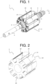
- Figure 1 discloses a view of an example of the rotor 1 according to a further aspect of the invention.
- the rotor 1 is, in particular, a separately excited rotor, also commonly referred as a wound rotor or a slip ring rotor.
- the rotor comprises a field coil connected to an external power supply through slip rings 7.
- the slip rings 7 especially correspond to electromechanical devices configured to allow the exchange of electric power between a rotating element and a fixed element, here respectively the field coil and the external power supply.
- the rotor 1 comprises a rotor shaft 4 configured to rotate around an axis X of rotation, and a rotor body 2 formed of a stack of laminations and being configured to be mounted coaxially on the rotor shaft 4.
- the laminations are especially stacked along the axis of rotation.
- the rotor body 2 may be for instance press-fitted on the rotor shaft 4.
- the rotor body 2 has a plurality of teeth 21 projecting radially and slots 22 corresponding to spaces between adjacent teeth of the plurality of teeth 21.
- the plurality of teeth 21 may notably comprise four, six, or eight teeth.
- Figure 2 illustrates a view of an example of the rotor body 2.
- the field coil is wound around each tooth of the plurality of teeth 21 and passing through the slots 22.
- the field coil especially forms coil ends projecting axially from respectively two axial ends 24 of the rotor body 2.
- the rotor 1 further comprises two end plates 5, as represented in Figure 1 , configured to come respectively against the two axial ends 24 of the rotor body 2.
- the two end plates 5 notably present an annular shape.
- the shape of both of the two end plates 5 may advantageously be substantially similar to the shape of the two axial ends 24 of the rotor body 2 such that to be able to cover the two axial ends 24.
- the field coil 3 passes through the slots 22 and over the two end plates 5.
- the two end plates 5 are notably located between the rotor body 2 and the coil ends such that to provide a mechanical holding of the stack of laminations and to electrically insulate the field coil from the rotor body 2.
- the two end plates 5 should at least be configured to come between the two axial ends 24 of rotor body 2 and the coil ends of the field coil.
- the two end plates 5 may have a plurality of end plate teeth corresponding to the plurality of teeth 21.
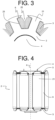
- Figure 3 schematically represent a partial cut view of an example of the rotor according to the invention.
- the rotor also comprises an insulation system 6 arranged on walls 23 of the slots 22 between the rotor body 2 and the field coil 3 such that to electrically insulate the rotor body 2 from the field coil 3.
- the walls 23 of the slots 22 especially correspond to faces of the rotor body 2 directed towards the slots 22.
- the insulation system has a plurality of parts, each part of the insulation system being associated to one of the slots of the rotor body.
- Figure 4 discloses another view of the example of the rotor according to the invention.
- the insulation system 6 and at least one of the two end plates 5 are overmolded on the rotor body 2 such that to form together a one-piece overmolded assembly.
- the insulation system 6 and the two end plates 5 are overmolded on the rotor body 2 such that to form together the one-piece overmolded assembly.
- the present invention gives thus the substantial gain of easing the manufacturing of the rotor, notably by reducing the number of pieces to assemble together. More precisely, compared to a conventional solution with two separate end plates, and a plurality of insulation papers depending on the number of teeth of the rotor body, the invention allows to prevent having to assemble all these different pieces together. For example, the invention enables to avoid using a glue for fixating at least one of the two end plates, as at least one of the two end plates is advantageously integrated to the one-piece overmolded assembly. Also, a glue could be used for fixating at least one of the two end plates to the corresponding axial end of the rotor body, if appropriate.
- the invention provides an alternative to using an insulation paper for providing electrical insulation between the rotor body and the field coil in-between the plurality of teeth.
- the invention prevents the problem of positioning the insulation paper, which is generally performed manually.
- the one-piece overmolded assembly is less likely to move during winding the field coil around the plurality of teeth, and during the in-service life of the rotor.
- the invention makes it possible to automatize the process of setting up the electrical insulation between the rotor body and the field coil.
- the one-piece overmolded assembly allows to improve the mechanical holding of the two end plates and of the insulation system, especially by reducing potential twisting or by preventing an improper positioning of either one of the two end plates or of the insulation system.
- at least one of the two end plates especially contributes to counter undesired relative axial movements of the one-piece overmolded assembly, and the insulation system contributes to counter undesired relative tangential movements of the one-piece overmolded assembly.
- the invention also allows to achieve more complex geometries and a higher quality of the two end plates and for the insulation system.
- the two end plates 5 and the insulation system 6 are made out of a plastic material able to electrically insulate the rotor body 2 from the field coil 3.
- the materials of the two end plates 5 and of the insulation system 6 are in particular compatible with an overmolding process or an injection molding process.
- the materials of the two end plates 5 and of the insulation system 6 should also present diamagnetic properties and a sufficient value of electrical resistivity.
- the two end plates 5 and the insulation system 6 are made out of a polyphthalamide material, commonly abbreviated as PPA.
- the two end plates 5 and the insulation system 6 may respectively be made out of a different material. This allows advantageously to adjust the material to the specific needs on one hand of the two end plates 5 and on the other hand of the insulation system 6, notably in terms of mechanical resistance, and of electric and magnetic properties.
- the one-piece overmolded assembly may further comprise cooling channels configured to channel a cooling liquid for cooling the rotor.
- the present invention also concerns a method for producing the rotor as described previously.
- the method comprises:
- overmolding comprises overmolding the rotor body 2 with the insulation system 6 and the two end plates 5.
Landscapes
- Engineering & Computer Science (AREA)
- Power Engineering (AREA)
- Manufacturing & Machinery (AREA)
- Insulation, Fastening Of Motor, Generator Windings (AREA)
Abstract
The invention concerns a rotor (1) comprising a rotor shaft (4) configured to rotate around an axis (X) of rotation; a rotor body (2) formed of a stack of laminations, a field coil, and two end plates (5) configured to come respectively against two axial ends of the rotor body (2). The rotor body (2) has a plurality of teeth (21) projecting radially and slots (22). The field coil is wound around each tooth of the plurality of teeth (21), the field coil passing through the slots (22) and over the two end plates (5). The rotor (1) further comprises an insulation system (6) arranged on walls (23) of the slots (22), the insulation system (6) and at least one of the two end plates (5) being overmolded on the rotor body (2) such that to form together a one-piece overmolded assembly.
Description
- The present invention belongs to the field of rotary electric machines configured to be on board of an automotive vehicle, such as an electric vehicle (EV) or a hybrid vehicle (HV).
- The present invention relates in particular to the field of separately excited rotors, also called wound rotors or slip ring rotors, integrated to rotary electric machines.
- As is known, an electric or a hybrid automotive vehicle presents an electric drive comprising a rotary electric machine which need to be supplied with electric power, for instance by a high voltage power supply battery, to deliver a mechanical power in order to ensure the propulsion of the vehicle.
- In a general manner, the rotary electric machine comprises a stator, referring to a fixed part of the rotary electric machine, and a rotor, referring to a rotating part of the rotary electric machine. The rotor then comprises a rotor shaft configured to ensure the transmission of the mechanical power between the rotary electric machine and an exterior driven apparatus, notably the wheels of the vehicle.
- In particular, it is known to have the rotor separately excited using a field coil. This type of rotors is commonly referred as wound rotors or slip ring rotors. Such a rotor comprises a rotor body formed of a stack of laminations and has a plurality of teeth projecting radially. Then, the field coil is configured to be wound around each of the plurality of teeth, while being electrically insulated from the stack of laminations.
- A conventional solution to electrically insulate the field coil from the stack of laminations is to provide an insulation paper in-between the plurality of teeth, as described in document
EP2807726A1 . In a general manner, the insulation paper is pre-folded and positioned manually on the stack of laminations before proceeding with the winding of the field coil above the insulation paper. The positioning of the insulation paper needs thus to be secured, otherwise the insulation paper could be damaged or misplaced during the winding process. This could reduce the quality of the insulation between the field coil and the stack of laminations. Moreover, securing the positioning of the insulation paper is complex from a manufacturing point of view. - Furthermore, the rotor commonly comprises two end plates located at two axial ends of the rotor body such that to provide a mechanical holding of the stack of laminations and an electrical insulation of the rotor body from coil ends of the field coil. The two end plates are to be well fixed to the rotor body to prevent a relative twist between the rotor body and the two end plates while the rotor is rotating. Such a relative twist induces a mechanical stress that could wear off or damage at least partially the rotor. In that aim, the two end plates are generally fixed on the rotor body using either an additional gluing material, or a mechanical fixing system, such as clamping elements, which impacts the cost of the rotor. Moreover, those solutions are complex to implement from a manufacturing point of view.
- In this context, the main objective of the present invention is to provide a rotor with an electrical insulation system, that is easier to produce and that presents an improved mechanical holding of an assembly of the rotor body and the two end plates.
- More precisely, the present invention concerns a rotor for a rotary electric machine, the rotor comprising a rotor shaft configured to rotate around an axis of rotation, a rotor body formed of a stack of laminations and being configured to be mounted coaxially on the rotor shaft, a field coil, two end plates configured to come respectively against two axial ends of the rotor body, and an insulation system. Moreover, the rotor body has a plurality of teeth projecting radially and slots corresponding to space between adjacent teeth of the plurality of teeth. The field coil is wound around each tooth of the plurality of teeth, the field coil passing through the slots and over the two end plates. The insulation system is arranged on walls of the slots between the rotor body and the field coil such that to electrically insulate the rotor body from the field coil. Then, the insulation system and at least one of the two end plates are overmolded on the rotor body such that to form together a one-piece overmolded assembly.
- The present invention provides the substantial gain of easing the manufacturing of the rotor, notably by reducing the number of pieces to assemble together. For example, the invention enables to avoid using a glue for fixating at least one of the two end plates. Besides, the invention provides an alternative to using a plurality of insulation papers for providing electrical insulation between the rotor body and the field coil in-between the plurality of teeth, which is complex and time consuming. The one-piece overmolded assembly is less likely to move during winding the field coil around the plurality of teeth, and during the in-service life of the rotor.
- Moreover, the one-piece overmolded assembly allows to improve the mechanical holding of the two end plates and of the insulation system, especially by reducing potential twisting or by preventing an improper positioning of either one of the two end plates or of the insulation system.
- In a preferred embodiment, the insulation system and the two end plates are overmolded on the rotor body such that to form together the one-piece overmolded assembly.
- Advantageously, the two end plates and the insulation system are made out of a plastic material able to electrically insulate the rotor body from the field coil.
- Advantageously, the two end plates and the insulation system are made out of a polyphthalamide material.
- Advantageously, the two end plates and the insulation system are respectively made out of a different material.
- The invention also concerns a method for producing the rotor as previously described, the method comprising:
- stacking the laminations together such that to form the rotor body;
- overmolding the rotor body with the insulation system and at least one of the two end plates.
- Advantageously, overmolding comprises overmolding the rotor body with the insulation system and the two end plates.
- According to an aspect of the invention, the invention relates to the rotary electric machine comprising the rotor as described previously. The rotary electric machine especially comprises a stator, the stator surrounding coaxially the rotor.
- Another aspect of the invention is the electric drive, comprising the rotary electric machine and an inverter configured to convert a direct current voltage coming from a high-voltage power supply battery into an alternating current voltage so as to drive the rotary electric machine. The AC voltage may be a multiphase AC voltage, especially a three-phase voltage.
- A further aspect of the invention is an electric of a hybrid vehicle, comprising the electric drive for driving the vehicle. The vehicle may comprise the high-voltage power supply battery, preferably a rechargeable battery for providing the DC voltage to the inverter, if applicable.
- These and other objects, features, aspects and advantages of the present invention will become apparent to those skilled in the art from the following detailed description, which, taken in conjunction with the annexed drawings, discloses preferred embodiments of the present invention.
- The invention will be better understood on reading the description that follows, and by referring to the appended drawings given as non-limiting examples, in which identical references are given to similar objects and in which:
-
Figure 1 is a schematic diagram of a view of an example of a rotor according to an embodiment of the invention; -
Figure 2 is a schematic diagram of a view of a rotor body of the example of the rotor according to an embodiment of the invention; -
Figure 3 is a schematic diagram of a partial cut view of an example of the rotor according to an embodiment of the invention; -
Figure 4 is a schematic diagram of another view of the example of the rotor according to an embodiment of the invention; -
Figure 5 is a schematic diagram of an automotive electric or hybrid vehicle comprising a rotary electric machine according to an embodiment of the invention. - Selected embodiments of the present invention will now be explained with reference to the drawings. It will be apparent to those skilled in the art from this disclosure that the following descriptions of the embodiments of the present invention are provided for illustration only and not for the purpose of limiting the invention as defined by the appended claims and their equivalents.
- In reference to
Figure 5 , an aspect of the invention is an electric vehicle or a hybrid electric automotive vehicle EV comprising wheels and an electric drive configured to drive at least indirectly at least one of the wheels of the vehicle. The vehicle may comprise a high-voltage power supply battery B, preferably a rechargeable battery, for providing electric power to the electric drive. - Another aspect of the invention is the electric drive comprising a rotary electric machine M and an inverter I configured to convert a direct current (DC) voltage coming from the high-voltage power supply battery B into an alternating current (AC) voltage in order to drive the rotary electric machine M. The rotary electric machine M may in particular be a three-phase rotary electric machine supplied with a three-phase AC voltage.
- The invention also relates to the rotary electric machine comprising a stator, referring to a fixed part of the rotary electric machine, and a rotor, referring to a rotating part of the rotary electric machine. In particular, the stator presents an annular shape and surrounds coaxially the rotor. Generally, the rotary electric machine comprises a casing covering both the stator and the rotor. Ordinarily, the stator comprises a stator body formed of a stack of stator laminations having a plurality of stator teeth projecting radially, and stator windings wound around the stator teeth.
-
Figure 1 discloses a view of an example of therotor 1 according to a further aspect of the invention. Therotor 1 is, in particular, a separately excited rotor, also commonly referred as a wound rotor or a slip ring rotor. In this type of rotor, the rotor comprises a field coil connected to an external power supply throughslip rings 7. The slip rings 7 especially correspond to electromechanical devices configured to allow the exchange of electric power between a rotating element and a fixed element, here respectively the field coil and the external power supply. - With reference to
Figure 1 , therotor 1 comprises arotor shaft 4 configured to rotate around an axis X of rotation, and arotor body 2 formed of a stack of laminations and being configured to be mounted coaxially on therotor shaft 4. The laminations are especially stacked along the axis of rotation. Therotor body 2 may be for instance press-fitted on therotor shaft 4. - Moreover, the
rotor body 2 has a plurality ofteeth 21 projecting radially andslots 22 corresponding to spaces between adjacent teeth of the plurality ofteeth 21. The plurality ofteeth 21 may notably comprise four, six, or eight teeth. -
Figure 2 illustrates a view of an example of therotor body 2. The field coil is wound around each tooth of the plurality ofteeth 21 and passing through theslots 22. The field coil especially forms coil ends projecting axially from respectively twoaxial ends 24 of therotor body 2. - The
rotor 1 further comprises twoend plates 5, as represented inFigure 1 , configured to come respectively against the twoaxial ends 24 of therotor body 2. The twoend plates 5 notably present an annular shape. The shape of both of the twoend plates 5 may advantageously be substantially similar to the shape of the twoaxial ends 24 of therotor body 2 such that to be able to cover the two axial ends 24. - Then, the
field coil 3 passes through theslots 22 and over the twoend plates 5. In other words, the twoend plates 5 are notably located between therotor body 2 and the coil ends such that to provide a mechanical holding of the stack of laminations and to electrically insulate the field coil from therotor body 2. For the late reason, the twoend plates 5 should at least be configured to come between the twoaxial ends 24 ofrotor body 2 and the coil ends of the field coil. Thus, the twoend plates 5 may have a plurality of end plate teeth corresponding to the plurality ofteeth 21. -
Figure 3 schematically represent a partial cut view of an example of the rotor according to the invention. The rotor also comprises aninsulation system 6 arranged onwalls 23 of theslots 22 between therotor body 2 and thefield coil 3 such that to electrically insulate therotor body 2 from thefield coil 3. Thewalls 23 of theslots 22 especially correspond to faces of therotor body 2 directed towards theslots 22. Notably, it can be noted that the insulation system has a plurality of parts, each part of the insulation system being associated to one of the slots of the rotor body. -
Figure 4 discloses another view of the example of the rotor according to the invention. Theinsulation system 6 and at least one of the twoend plates 5 are overmolded on therotor body 2 such that to form together a one-piece overmolded assembly. - In a preferred embodiment, the
insulation system 6 and the twoend plates 5 are overmolded on therotor body 2 such that to form together the one-piece overmolded assembly. - The present invention gives thus the substantial gain of easing the manufacturing of the rotor, notably by reducing the number of pieces to assemble together. More precisely, compared to a conventional solution with two separate end plates, and a plurality of insulation papers depending on the number of teeth of the rotor body, the invention allows to prevent having to assemble all these different pieces together. For example, the invention enables to avoid using a glue for fixating at least one of the two end plates, as at least one of the two end plates is advantageously integrated to the one-piece overmolded assembly. Also, a glue could be used for fixating at least one of the two end plates to the corresponding axial end of the rotor body, if appropriate.
- Besides, the invention provides an alternative to using an insulation paper for providing electrical insulation between the rotor body and the field coil in-between the plurality of teeth. Thus, the invention prevents the problem of positioning the insulation paper, which is generally performed manually. The one-piece overmolded assembly is less likely to move during winding the field coil around the plurality of teeth, and during the in-service life of the rotor. In addition, the invention makes it possible to automatize the process of setting up the electrical insulation between the rotor body and the field coil.
- Moreover, the one-piece overmolded assembly allows to improve the mechanical holding of the two end plates and of the insulation system, especially by reducing potential twisting or by preventing an improper positioning of either one of the two end plates or of the insulation system. In fact, at least one of the two end plates especially contributes to counter undesired relative axial movements of the one-piece overmolded assembly, and the insulation system contributes to counter undesired relative tangential movements of the one-piece overmolded assembly.
- The invention also allows to achieve more complex geometries and a higher quality of the two end plates and for the insulation system.
- In an advantageous manner, the two
end plates 5 and theinsulation system 6 are made out of a plastic material able to electrically insulate therotor body 2 from thefield coil 3. The materials of the twoend plates 5 and of theinsulation system 6 are in particular compatible with an overmolding process or an injection molding process. The materials of the twoend plates 5 and of theinsulation system 6 should also present diamagnetic properties and a sufficient value of electrical resistivity. - For instance, the two
end plates 5 and theinsulation system 6 are made out of a polyphthalamide material, commonly abbreviated as PPA. - Although, the two
end plates 5 and theinsulation system 6 may respectively be made out of a different material. This allows advantageously to adjust the material to the specific needs on one hand of the twoend plates 5 and on the other hand of theinsulation system 6, notably in terms of mechanical resistance, and of electric and magnetic properties. - The one-piece overmolded assembly may further comprise cooling channels configured to channel a cooling liquid for cooling the rotor.
- The present invention also concerns a method for producing the rotor as described previously. The method comprises:
- stacking the laminations together such that to form the
rotor body 2; - overmolding the
rotor body 2 with theinsulation system 6 and at least one of the twoend plates 5. - Then, in the preferred embodiment, overmolding comprises overmolding the
rotor body 2 with theinsulation system 6 and the twoend plates 5. - Although embodiments have been described with reference to a number of illustrative embodiments thereof, it should be understood that numerous other modifications and embodiments can be devised by those skilled in the art that will fall within the spirit and scope of the principles of this disclosure.
Claims (8)
- A rotor (1) for a rotary electric machine (M), the rotor (1) comprising:- a rotor shaft (4) configured to rotate around an axis (X) of rotation;- a rotor body (2) formed of a stack of laminations and being configured to be mounted coaxially on the rotor shaft (4), the rotor body (2) having a plurality of teeth (21) projecting radially and slots (22) corresponding to space between adjacent teeth of the plurality of teeth (21);- two end plates (5) configured to come respectively against two axial ends (24) of the rotor body (2);- a field coil (3) wound around each tooth of the plurality of teeth (21), the field coil (3) passing through the slots (22) and over the two end plates (5);- an insulation system (6) arranged on walls (23) of the slots (22) between the rotor body (2) and the field coil (3) such that to electrically insulate the rotor body (2) from the field coil (3);characterized in that the insulation system (6) and at least one of the two end plates (5) are overmolded on the rotor body (2) such that to form together a one-piece overmolded assembly.
- The rotor (1) as claimed in claim 1, wherein the insulation system (6) and the two end plates (5) are overmolded on the rotor body (2) such that to form together the one-piece overmolded assembly.
- The rotor (1) as claimed in any of the preceding claims, wherein the two end plates (5) and the insulation system (6) are made out of a plastic material able to electrically insulate the rotor body (2) from the field coil (3).
- The rotor (1) as claimed in any of the preceding claims, wherein the two end plates (5) and the insulation system (6) are made out of a polyphthalamide material.
- The rotor (1) as claimed in any of the preceding claims, wherein the two end plates (5) and the insulation system (6) are respectively made out of a different material.
- A method for producing the rotor (1) as claimed in any of the preceding claims, the method comprising:- stacking the laminations together such that to form the rotor body (2);- overmolding the rotor body (2) with the insulation system (6) and at least one of the two end plates (5).
- The method as claimed in the previous claim, wherein overmolding comprises overmolding the rotor body (2) with the insulation system (6) and the two end plates (5).
- A rotary electric machine (M) for an electric or a hybrid vehicle (EV), the rotary electric machine (M) comprising the rotor (1) according to any of the claims 1 to 5.
Priority Applications (1)
| Application Number | Priority Date | Filing Date | Title |
|---|---|---|---|
| EP21217471.8A EP4203267A1 (en) | 2021-12-23 | 2021-12-23 | Overmolded separately excited rotor |
Applications Claiming Priority (1)
| Application Number | Priority Date | Filing Date | Title |
|---|---|---|---|
| EP21217471.8A EP4203267A1 (en) | 2021-12-23 | 2021-12-23 | Overmolded separately excited rotor |
Publications (1)
| Publication Number | Publication Date |
|---|---|
| EP4203267A1 true EP4203267A1 (en) | 2023-06-28 |
Family
ID=79021677
Family Applications (1)
| Application Number | Title | Priority Date | Filing Date |
|---|---|---|---|
| EP21217471.8A Withdrawn EP4203267A1 (en) | 2021-12-23 | 2021-12-23 | Overmolded separately excited rotor |
Country Status (1)
| Country | Link |
|---|---|
| EP (1) | EP4203267A1 (en) |
Cited By (1)
| Publication number | Priority date | Publication date | Assignee | Title |
|---|---|---|---|---|
| DE102023209563A1 (en) * | 2023-09-28 | 2025-04-03 | Magna powertrain gmbh & co kg | Electrical machine with wound rotor, as well as rotor and manufacture of the electrical machine |
Citations (5)
| Publication number | Priority date | Publication date | Assignee | Title |
|---|---|---|---|---|
| EP2807726A1 (en) | 2012-01-26 | 2014-12-03 | Continental Automotive GmbH | Rotor for a rotating electrical machine and electric motor |
| DE102016221711A1 (en) * | 2015-11-20 | 2017-05-24 | Bosch Automotive Products (Changsha) Co., Ltd. | Stator and electric motor with the same |
| DE102017212290A1 (en) * | 2017-07-18 | 2019-01-24 | Volkswagen Aktiengesellschaft | Stator or rotor for an electric machine and electric machine |
| WO2019029964A1 (en) * | 2017-08-10 | 2019-02-14 | Bayerische Motoren Werke Aktiengesellschaft | Rotor |
| US20200177046A1 (en) * | 2018-11-30 | 2020-06-04 | Valeo Siemens Eautomotive Germany Gmbh | Rotor with a winding for an electrical machine |
-
2021
- 2021-12-23 EP EP21217471.8A patent/EP4203267A1/en not_active Withdrawn
Patent Citations (5)
| Publication number | Priority date | Publication date | Assignee | Title |
|---|---|---|---|---|
| EP2807726A1 (en) | 2012-01-26 | 2014-12-03 | Continental Automotive GmbH | Rotor for a rotating electrical machine and electric motor |
| DE102016221711A1 (en) * | 2015-11-20 | 2017-05-24 | Bosch Automotive Products (Changsha) Co., Ltd. | Stator and electric motor with the same |
| DE102017212290A1 (en) * | 2017-07-18 | 2019-01-24 | Volkswagen Aktiengesellschaft | Stator or rotor for an electric machine and electric machine |
| WO2019029964A1 (en) * | 2017-08-10 | 2019-02-14 | Bayerische Motoren Werke Aktiengesellschaft | Rotor |
| US20200177046A1 (en) * | 2018-11-30 | 2020-06-04 | Valeo Siemens Eautomotive Germany Gmbh | Rotor with a winding for an electrical machine |
Cited By (1)
| Publication number | Priority date | Publication date | Assignee | Title |
|---|---|---|---|---|
| DE102023209563A1 (en) * | 2023-09-28 | 2025-04-03 | Magna powertrain gmbh & co kg | Electrical machine with wound rotor, as well as rotor and manufacture of the electrical machine |
Similar Documents
| Publication | Publication Date | Title |
|---|---|---|
| CN113273064B (en) | Rotor of a rotating electrical machine | |
| US20140175935A1 (en) | Rotary electric machine | |
| US12308720B2 (en) | Wedge element for an electric excited rotor | |
| US11355986B2 (en) | Rotor with a winding for an electrical machine | |
| US20230208221A1 (en) | Rotor for a rotary electric machine having a barrier protecting coil ends of the rotor | |
| US12407200B2 (en) | Stator core, assembly comprising a stator core and slot linings, stator, electric machine and vehicle | |
| KR20230096884A (en) | Electric excited rotor having an insulation paper and method for producing the same | |
| US8604659B2 (en) | Stator with insulation for an electric motor, insulation for a stator, and electric power tool | |
| US9118231B2 (en) | Stator of rotating electrical machine and rotating electrical machine | |
| US20230208088A1 (en) | Electrical connector for a separately excited rotor | |
| EP4203276A1 (en) | Electrical connector for a separately excited rotor | |
| CN116264420A (en) | Rotors for rotating electrical machines | |
| JP2021529498A (en) | Rotating electromechanical with rotor form to reduce torque ripple | |
| EP4224682A1 (en) | Electrical connecting assembly for a separately excited rotor | |
| US20250055358A1 (en) | Interlocked lamination package for winding of eesm rotor by process | |
| WO2023118469A1 (en) | Guided wedge element for an electric excited rotor | |
| US20250015682A1 (en) | A rotor assembly method | |
| JP7836539B2 (en) | Rotating machinery and series coil group | |
| EP4203275A1 (en) | Electrical connector for a separately excited rotor | |
| EP4203248A1 (en) | Welding of a stack of laminations for a rotor | |
| EP4203249A1 (en) | Electrical insulation for a separately excited rotor | |
| US20260106499A1 (en) | Stator of an electric machine, motor vehicle | |
| WO2023144384A1 (en) | Integrated insulation element and wedge elements for an electric excited rotor | |
| EP4199315A1 (en) | A rotor for a rotary electric machine | |
| CN110417224B (en) | Rotating electrical machine with configuration for reducing third-order harmonics |
Legal Events
| Date | Code | Title | Description |
|---|---|---|---|
| PUAI | Public reference made under article 153(3) epc to a published international application that has entered the european phase |
Free format text: ORIGINAL CODE: 0009012 |
|
| STAA | Information on the status of an ep patent application or granted ep patent |
Free format text: STATUS: THE APPLICATION HAS BEEN PUBLISHED |
|
| AK | Designated contracting states |
Kind code of ref document: A1 Designated state(s): AL AT BE BG CH CY CZ DE DK EE ES FI FR GB GR HR HU IE IS IT LI LT LU LV MC MK MT NL NO PL PT RO RS SE SI SK SM TR |
|
| STAA | Information on the status of an ep patent application or granted ep patent |
Free format text: STATUS: THE APPLICATION IS DEEMED TO BE WITHDRAWN |
|
| 18D | Application deemed to be withdrawn |
Effective date: 20240103 |