EP4203175A1 - Lithium secondary battery and method of replenishing electrolyte in lithium secondary battery - Google Patents
Lithium secondary battery and method of replenishing electrolyte in lithium secondary battery Download PDFInfo
- Publication number
- EP4203175A1 EP4203175A1 EP22213388.6A EP22213388A EP4203175A1 EP 4203175 A1 EP4203175 A1 EP 4203175A1 EP 22213388 A EP22213388 A EP 22213388A EP 4203175 A1 EP4203175 A1 EP 4203175A1
- Authority
- EP
- European Patent Office
- Prior art keywords
- unit
- sub
- electrolyte
- secondary battery
- lithium secondary
- Prior art date
- Legal status (The legal status is an assumption and is not a legal conclusion. Google has not performed a legal analysis and makes no representation as to the accuracy of the status listed.)
- Granted
Links
Images


Classifications
-
- H—ELECTRICITY
- H01—ELECTRIC ELEMENTS
- H01M—PROCESSES OR MEANS, e.g. BATTERIES, FOR THE DIRECT CONVERSION OF CHEMICAL ENERGY INTO ELECTRICAL ENERGY
- H01M10/00—Secondary cells; Manufacture thereof
- H01M10/05—Accumulators with non-aqueous electrolyte
- H01M10/052—Li-accumulators
- H01M10/0525—Rocking-chair batteries, i.e. batteries with lithium insertion or intercalation in both electrodes; Lithium-ion batteries
-
- H—ELECTRICITY
- H01—ELECTRIC ELEMENTS
- H01M—PROCESSES OR MEANS, e.g. BATTERIES, FOR THE DIRECT CONVERSION OF CHEMICAL ENERGY INTO ELECTRICAL ENERGY
- H01M50/00—Constructional details or processes of manufacture of the non-active parts of electrochemical cells other than fuel cells, e.g. hybrid cells
- H01M50/60—Arrangements or processes for filling or topping-up with liquids; Arrangements or processes for draining liquids from casings
- H01M50/673—Containers for storing liquids; Delivery conduits therefor
- H01M50/682—Containers for storing liquids; Delivery conduits therefor accommodated in battery or cell casings
-
- H—ELECTRICITY
- H01—ELECTRIC ELEMENTS
- H01M—PROCESSES OR MEANS, e.g. BATTERIES, FOR THE DIRECT CONVERSION OF CHEMICAL ENERGY INTO ELECTRICAL ENERGY
- H01M10/00—Secondary cells; Manufacture thereof
- H01M10/05—Accumulators with non-aqueous electrolyte
- H01M10/052—Li-accumulators
-
- H—ELECTRICITY
- H01—ELECTRIC ELEMENTS
- H01M—PROCESSES OR MEANS, e.g. BATTERIES, FOR THE DIRECT CONVERSION OF CHEMICAL ENERGY INTO ELECTRICAL ENERGY
- H01M50/00—Constructional details or processes of manufacture of the non-active parts of electrochemical cells other than fuel cells, e.g. hybrid cells
- H01M50/60—Arrangements or processes for filling or topping-up with liquids; Arrangements or processes for draining liquids from casings
- H01M50/609—Arrangements or processes for filling with liquid, e.g. electrolytes
-
- Y—GENERAL TAGGING OF NEW TECHNOLOGICAL DEVELOPMENTS; GENERAL TAGGING OF CROSS-SECTIONAL TECHNOLOGIES SPANNING OVER SEVERAL SECTIONS OF THE IPC; TECHNICAL SUBJECTS COVERED BY FORMER USPC CROSS-REFERENCE ART COLLECTIONS [XRACs] AND DIGESTS
- Y02—TECHNOLOGIES OR APPLICATIONS FOR MITIGATION OR ADAPTATION AGAINST CLIMATE CHANGE
- Y02E—REDUCTION OF GREENHOUSE GAS [GHG] EMISSIONS, RELATED TO ENERGY GENERATION, TRANSMISSION OR DISTRIBUTION
- Y02E60/00—Enabling technologies; Technologies with a potential or indirect contribution to GHG emissions mitigation
- Y02E60/10—Energy storage using batteries
-
- Y—GENERAL TAGGING OF NEW TECHNOLOGICAL DEVELOPMENTS; GENERAL TAGGING OF CROSS-SECTIONAL TECHNOLOGIES SPANNING OVER SEVERAL SECTIONS OF THE IPC; TECHNICAL SUBJECTS COVERED BY FORMER USPC CROSS-REFERENCE ART COLLECTIONS [XRACs] AND DIGESTS
- Y02—TECHNOLOGIES OR APPLICATIONS FOR MITIGATION OR ADAPTATION AGAINST CLIMATE CHANGE
- Y02P—CLIMATE CHANGE MITIGATION TECHNOLOGIES IN THE PRODUCTION OR PROCESSING OF GOODS
- Y02P70/00—Climate change mitigation technologies in the production process for final industrial or consumer products
- Y02P70/50—Manufacturing or production processes characterised by the final manufactured product
Definitions
- the present invention relates to a lithium secondary battery and a method for replenishing an electrolyte in a lithium secondary battery. More particularly, the present invention relates to a lithium secondary battery including an electrode assembly and an electrolyte impregnating the electrode assembly, and a method for replenishing an electrolyte in a lithium secondary battery
- a secondary battery which can be charged and discharged repeatedly includes, e.g., a lithium secondary battery, a nickel-cadmium battery, a nickel-hydrogen battery, etc.
- the lithium secondary battery is highlighted due to high operational voltage and energy density per unit weight, a high charging rate, a compact dimension, etc.
- a low-capacity lithium secondary battery may be used as a power source for a small electronic device such as a cellular phone, a laptop computer, a camcorder, etc.
- a high-capacity lithium secondary battery may be used as a power source for a large electronic device such as an electric vehicle, a hybrid vehicle, etc.
- the lithium secondary battery may include an electrode assembly including a cathode, an anode and a separation layer interposed therebetween, and an electrolyte immersing the electrode assembly.
- the lithium secondary battery may further include a case for accommodating the electrode assembly and the electrolyte.
- the lithium secondary battery may be charged and discharged through an electrochemical reaction of the cathode, the anode, and the electrolyte.
- the electrolyte When the lithium secondary battery is repeatedly charged and discharged, the electrolyte may be transformed due to a side reaction, and an amount of the electrolyte in the lithium secondary battery may be gradually reduced. Accordingly, a capacity retention of the lithium secondary battery may also be gradually decreased, thereby reducing a life-span.
- Korean Published Patent Application No. 10-2011-0132856 discloses a method of replenishing an electrolyte in a lithium secondary battery.
- a lithium secondary battery having improved life-span property.
- a lithium secondary battery includes an electrode assembly including a cathode and an anode facing the cathode, a case accommodating the electrode assembly, an electrolyte accommodated in the case together with the electrode assembly, and an electrolyte storage unit inserted into the case to supply a supplementary electrolyte.
- the electrolyte storage unit includes a first unit including a first body having a tubular structure and first holes formed through the first body, and a sub-unit including a tubular body and sub-holes formed through the tubular body. The sub-unit is inserted into the first unit so that the sub-holes are offset from the first holes.
- the electrolyte storage unit may further include a second unit that includes a second body having a tubular structure and second holes formed through the second body.
- the second unit may be inserted between the first unit and the sub-unit so that at least one of the second holes overlaps at least one of the first holes.
- the second holes may be arranged to be offset from the sub-holes.
- an inner surface of the first body and an outer surface of the second body may have a screw structure to be fastened to each other.
- the first unit may have a first coefficient of thermal expansion
- the second unit may have a second coefficient of thermal expansion different from the first coefficient of thermal expansion
- the second coefficient of thermal expansion may be greater than the first coefficient of thermal expansion.
- the second unit may be physically separable from the first unit at a temperature of -20°C or less, or 40°C or higher.
- the sub-unit may include a first sub-unit and a second sub-unit which are inserted into both end portions of the first unit.
- the electrolyte storage unit may further include a first packing unit coupled to one end portion of the first sub-unit, and a second packing unit coupled to one end portion of the second sub-unit.
- the first sub-unit and the second sub-unit may be disposed in the first unit to be spaced apart from each other in a longitudinal direction of the first unit.
- the first sub-unit and the second sub-unit may be movable by an external force in the longitudinal direction so that at least one of the sub-holes overlaps at least one of the first holes.
- the case may include a first space accommodating the electrode assembly and the electrolyte, a second space into which the electrolyte storage unit is inserted, and a passage portion through which the supplementary electrolyte is capable of being transferred between the first space and the second space.
- the second space may extend in a longitudinal direction of the electrode assembly.
- the passage portion may include a sealing line portion that is capable of being opened by a pressure due to a discharge of the supplementary electrolyte.
- the lithium secondary battery according to the above-described embodiments is prepared.
- the supplementary electrolyte is discharged from the electrolyte storage unit to an peripheral portion of the electrode assembly when at least a portion of the electrolyte is consumed.
- the sub-unit in the discharging the supplementary electrolyte, may be moved so that at least one of the sub-holes overlaps at least one of the first holes.
- the electrolyte storage unit may further include a second unit including a second body having a tubular structure and second holes formed thorough the second body.
- the second unit may be inserted between the first unit and the sub-unit so that at least one of the second holes overlaps at least one of the first holes.
- the lithium secondary battery may be cooled or heated to form a gap between the first unit and the second unit in the electrolyte storage unit from which the supplementary electrolyte is discharged.
- a replacement unit that includes a second unit and a sub-unit filled with a supplementary electrolyte may be prepared. The replacement unit filled with the supplementary electrolyte may be inserted into the first unit to separate the second unit and the sub-unit from which the supplementary electrolyte is discharged from the first unit.
- a lithium secondary battery may include an electrode assembly and an electrolyte accommodated in a main-chamber of a case and an electrolyte storage unit including a supplementary electrolyte.
- the electrolyte storage unit may supply the supplementary electrolyte to the main chamber Accordingly, a battery cell may have improved life-span properties.
- the supplementary electrolyte may be supplied to the main-chamber while maintaining an airtightness of the main-chamber. Accordingly, damages to the lithium secondary battery due to an infiltration of external air and moisture when replenishing the electrolyte may be prevented.
- the supplementary electrolyte may be added to the electrolyte storage unit while maintaining the airtightness of the main-chamber. Accordingly, the lithium secondary battery may have more improved life-span properties.
- a lithium secondary battery 1 includes an electrode assembly 150; an electrolyte (not illustrated) impregnating the electrode assembly 150; an electrolyte storage unit 5 containing a supplementary electrolyte; and a case 160 accommodating the electrode assembly 150, the electrolyte and the electrolyte storage unit 5.
- the electrolyte storage unit 5 may be inserted into the case 160 to be adjacent to the electrode assembly 150.
- the case 160 may include a first space 172 accommodating the electrode assembly 150 and the electrolyte impregnating the electrode assembly 150; and a second space 174 into which the electrolyte storage unit 5 is inserted.
- a longitudinal direction of the electrode assembly 150 and a longitudinal direction of the electrolyte storage unit 5 may be parallel to each other.
- the longitudinal direction of the electrode assembly 150 may refer to a direction parallel to a long side direction of a cathode (or an anode).
- the longitudinal direction of the electrolyte storage unit 5 may refer to a direction parallel to a direction in which the electrolyte storage unit 5 is inserted into the case 160.
- a longitudinal direction of the first unit 10, a longitudinal direction of a second unit 20, and a longitudinal direction of sub-units (a first sub-unit and a second sub-unit) described later may refer to a direction parallel to the direction in which the electrolyte storage unit 5 is inserted into the case 160.
- the second space 174 may extend in the longitudinal direction of the electrode assembly 150.
- a length of the electrode assembly 150 in the longitudinal direction and a length of the electrolyte storage unit 5 in the longitudinal direction may be equivalent to each other.
- the case 160 may further include a passage portion 176 between the first space 172 and the second space 174.
- the supplementary electrolyte accommodated in the electrolyte storage unit 5 may be transferred from the second space 174 to the first space 172.
- the case 160 may include a sealing portion and a non-sealing portion at an outer peripheral portion.
- the case 160 may include three sealing portions 162, 164 and 166 and a non-sealing portion 168.
- the non-sealing portion 168 may be formed by folding one sheet.
- the first space 172 may include an enclosed space.
- the second space 174 may include an enclosed space or a space in which at least one side is open.
- an outer surface of the electrolyte storage unit 5 (e.g., an outer surface of the first unit) may be in a close contact with an inner surface of the second space 174 so that the supplementary electrolyte may not be leaked to an outside of the case 160.
- the electrolyte storage unit 5 may include a first unit 10 and a sub-unit inserted into the first unit 10 .
- the first unit 10 may include a first body 12 having a tubular structure and first holes 14 formed in the first body 12.
- the first body 12 may have a tubular structure in which both ends are open.
- at least one of the first holes 14 may be connected to the passage portion 176 .
- the first holes 14 may be formed in a line or in series in the first body 12 along the longitudinal direction of the first unit 10 .
- the sub-unit includes a body having a tubular structure (hereinafter, abbreviated as a tubular body) and sub-holes formed in the tubular body.
- the sub-unit may be inserted into the first unit 10 such that the sub-holes may be offset from or may not overlap the first holes 14. Accordingly, an enclosed space may be formed in the first unit 10 and the sub-unit.
- the supplementary electrolyte may be accommodated in the enclosed space.
- the sub-holes may be formed in a line or in series in the tubular body along the longitudinal direction of the sub-unit.
- the sub-unit may include a first sub-unit 30 and a second sub-unit 40.
- the first sub-unit 30 and the second sub-unit 40 may each be inserted into both ends of the first unit 10.
- first sub-unit 30 and the second sub-unit 40 may be disposed in the first unit 10 to be spaced apart from each other in the longitudinal direction of the first unit 10.
- the first sub-unit 30 may include a first tubular body 32 and first sub-holes 34 formed in the first tubular body 32.
- the first tubular body 32 may have a tubular structure in which one end is closed and the other end (an end opposite to the one end in the longitudinal direction) is opened.
- the first sub-holes 34 may be formed in a line or in series in the first tubular body 32 along the longitudinal direction of the first sub-unit 30.
- the second sub-unit 40 may include a second tubular body 42 and second sub-holes 44 formed in the second tubular body 42.
- the second tubular body 42 may have a tubular structure in which one end is closed and the other end is opened.
- the second sub-holes 44 may be formed in a line or in series in the second tubular body 42 along the longitudinal direction of the second sub-unit 40.
- the electrolyte storage unit 5 may further include a second unit 20 inserted between the first unit 10 and the sub-units.
- the second unit 20 may include a second body 22 having a tubular structure and second holes 24 formed in the second body 22.
- the second body 22 may have a tubular structure in which both ends are opened.
- the second holes 24 may be formed in a line or in series in the second body 22 along the longitudinal direction of the second unit 20.
- the second unit 20 may be inserted into the first unit 10 such that at least one of the second holes 24 overlaps at least one of the first holes 14.
- the sub-units 30 and 40 (not illustrated in FIG. 6 ) may be inserted into the second unit 20. Accordingly, the second unit 20 may be disposed between the first unit 10 and the sub-unit.
- the first unit 10 and the second unit 20 may include the same number of holes.
- the first holes 14 and the second holes 24 may be disposed to overlap each other.
- the first sub-unit 30 and the second sub-unit 40 may be inserted into the second unit 20.
- the first sub-unit 30 and the second sub-unit 40 may each be inserted from both ends of the second unit 10.
- the first sub-unit 30 and the second sub-unit 40 may be disposed in the second unit 20 to be spaced apart from each other in the longitudinal direction of the second unit 20.
- first holes 14, the second holes 24, the first sub-holes 34 and the second sub-holes 44 may be arranged in a line or in series along the longitudinal direction of the first unit 10.
- the enclosed one end of the first sub-unit 30 and the enclosed one end of the second sub-unit 40 may be disposed to face the outside of the case 160.
- the second holes 24, the first sub-holes 34 and the second sub-holes 44 may be offset from each other. Accordingly, an enclosed space 50 may be formed in the second unit 20, the first sub-unit 30 and the second sub-unit 40.
- the supplementary electrolyte may be accommodated in the enclosed space 50 .
- the first sub-unit 30 may include a first packing unit 36 coupled to one end portion thereof.
- the first packing unit 36 may be disposed on an outer surface of the closed one end portion of the first tubular body 32.
- the first packing portion 36 may be disposed between the second unit 20 and the first sub-unit 30. An airtightness of the enclosed space 50 may be improved by the first packing unit 36.
- the first packing unit 36 may surround an outer surface of the enclosed one end portion of the first tubular body 32.
- the second sub-unit 40 may include a second packing unit 46 coupled to one end portion thereof.
- the second packing unit 46 may be disposed on an outer surface of the closed one end portion of the second tubular body 42.
- the second packing unit 46 may be disposed between the second unit 20 and the second sub-unit 40. An airtightness of the enclosed space 50 may be improved by the second packing unit 46.
- the second packing unit 46 may surround an outer surface of the closed one end portion of the second tubular body 42.
- each of the first sub-unit 30 and the second sub-unit 40 may have a packing unit coupled to an end portion opposite to the one end portion (i.e., the other end portion). Accordingly, the airtightness of the closed space 50 may be further improved.
- the packing unit may include an elastic material.
- the elastic material may include a natural rubber, a synthetic rubber or an elastomer.
- the elastomer may include a polyolefin-based elastomer, a urethane-based elastomer, a styrene-based block copolymer, a vinyl chloride elastomer, a chlorinated polyethylene elastomer, a polyester-based elastomer, a polyamide-based elastomer, a fluorine-based elastomer, silicone-based elastomers, etc.
- a material having chemical resistance to the electrolyte may be used.
- the material of the packing unit may include the polyolefin-based resin.
- the polyolefin-based resin may include polyethylene, etc.
- the lithium secondary battery 1 when the lithium secondary battery 1 is repeatedly charged and discharged, at least a portion of the electrolyte contained in the first space 172 may be consumed.
- At least one of the first sub-unit 30 and the second sub-unit 40 may be movable at an inside of the first unit 10 in a direction in which a volume of the enclosed space 50 is reduced by an external force (e.g., the longitudinal direction of the first unit).
- At least one of the first sub-holes 34 is arranged to overlap at least one of the first holes 14 so that the enclosed space 50 may be opened.
- at least one of the second sub-holes 44 is arranged to overlap at least one of the first holes 14 so that the enclosed space 50 may be opened.
- the supplementary electrolyte may flow through at least one of the first sub-holes 34 and the second sub-holes 44, at least one of the first holes 14, and the passage portion 176 to be discharged into the first space 172.
- the enclosed one end portion of the first sub-unit 30 and the enclosed one end portion of the second sub-unit 40 may each be disposed to face the outside of the case 160.
- the second holes 24, the first sub-holes 34 and the second sub-holes 44 may be arranged to be offset from each other, so that the enclosed space 50 may be formed in the second unit 20, the first sub-unit 30 and the second sub-unit 40.
- the supplementary electrolyte may be accommodated in the enclosed space 50.
- the first sub-unit 30 and the second sub-unit 40 may be moved at an inside of the second unit 20 in a direction in which a volume of the enclosed space 50 is reduced by an external force (e.g., the longitudinal direction of the second unit). Accordingly, the second holes 24 and at least one of the first sub-holes 34 and the second sub-holes 44 may overlap each other. Thus, the enclosed space 50 may be opened.
- the first holes 14 and the second holes 24 may overlap each other.
- the supplementary electrolyte may be moved to the first space 172 through the first holes 14 and the passage portion 176.
- the electrolyte may be replenished while maintaining the airtightness of the first space 172. Accordingly, damages to the lithium secondary battery due to a permeation of external air and moisture when replenishing the electrolyte may be prevented.
- the passage portion 176 may include a sealing line portion 178. Accordingly, the airtightness of the first space 172 may be further improved.
- the sealing line portion 178 may be opened by a discharging pressure of the supplementary electrolyte.
- the first unit 10 may have a first coefficient of thermal expansion
- the second unit 20 may have a second coefficient of thermal expansion different from the first coefficient of thermal expansion.
- the coefficient of thermal expansion may be a linear expansion coefficient.
- a gap may be generated between the first unit 10 and the second unit 20.
- the gap may be formed between the first unit 10 and the second unit 20 by cooling or heating the electrolyte storage unit 5 to the predetermined temperature.
- the second unit 20 may be physically separated from the first unit 10 by the gap.
- the gap may not be formed at room temperature, and thus the second unit 20 may not be physically separated from the first unit 10 without damaging the first unit 10.
- the sub-unit may also be separated from the first unit 10 together with the second unit 20.
- the second unit 20 may be physically separated from the first unit 10 at a temperature ranging from -30°C to -20°C.
- the second unit 20 may be physically separated from the first unit 10 at a temperature ranging 40°C to 50°C.
- a gap may be formed between the first unit 10 and the second unit 20 in which the supplementary electrolyte is consumed, so that the second unit 20 in which the supplementary electrolyte is consumed and the sub-unit may be separated from the first unit 10.
- the supplementary electrolyte may be newly charged in the second unit 20 where the supplementary electrolyte is consumed, and the second unit 20 may be inserted again into the first unit 10.
- the sealing line portion 178 may be reformed to maintain the airtightness of the first space 172.
- a replacement unit 60 including the second unit 20 filled with the supplementary electrolyte and the sub-unit may be additionally prepared and inserted into the first unit 10.
- a gap may be formed between the first unit 10 and the second unit 20 in which the supplementary electrolyte is consumed.
- the replacement unit 60 may be inserted into the first unit 10, and the second unit 20 in which the supplementary electrolyte is consumed may be separated by being pushed from the first unit 10.
- the sub-unit may be separated from the first unit 10 together with the second unit 20. In this case, the replacement may be performed while maintaining the airtightness of the first space 172.
- the replacement may be performed under a low-temperature condition (e.g., -20°C or less, or -30°C or less) or a high-temperature condition (e.g., 40°C or higher, or 50°C or higher).
- a low-temperature condition e.g., -20°C or less, or -30°C or less
- a high-temperature condition e.g., 40°C or higher, or 50°C or higher.
- the replacement may be performed under the low-temperature condition. In this case, deformation of the electrolyte under the high temperature condition may be avoided.
- an absolute difference between the first coefficient of thermal expansion and the second coefficient of thermal expansion may be 5 ⁇ m/K or more, 10 ⁇ m/K or more, or 20 ⁇ m/K or more. Within the above range, the separation may be implemented without deterioration of the lithium secondary battery.
- the absolute difference between the first coefficient of thermal expansion and the second coefficient of thermal expansion may be 50 ⁇ m/K or less, 40 ⁇ m/K or less, or 30 ⁇ m/K or less.
- the airtightness of the first space 172 may be improved.
- penetration of external air and moisture into the first space 172 during the separation process may be effectively prevented.
- a high-temperature environment may be created by a heat generation during repeated charging and discharging of the lithium secondary battery.
- the second coefficient of thermal expansion may be greater than the first coefficient of thermal expansion.
- the gap between the first unit 10 and the second unit 20 may be formed at a low temperature, and the gap may not be formed at a high temperature. Accordingly, high-temperature durability of the electrolyte storage unit 5 may be improved.
- each of the first unit 10 and the second unit 20 may be formed of a metal such as stainless steel, copper, zinc, aluminum, manganese, tungsten, molybdenum, nickel, iron, silver, etc.; a polymer such as EP (Engineering plastic) and PET; and a ceramic such as Al 2 O 3 and TiO 2 . These may be used alone or in combination thereof
- the first unit 10 may include stainless steel and the second unit 20 may include aluminum.
- the first unit 10, the second unit 20 and the sub-unit may include a material that may have a chemical resistance to the supplementary electrolyte (e.g., that nay not cause a side reaction with the supplementary electrolyte).
- the sub-unit may include a metal such as stainless steel, copper, zinc, aluminum, manganese, tungsten, molybdenum, nickel, iron, silver, etc.; a polymer such as EP (Engineering plastic) and PET; and a ceramic such as Al 2 O 3 and TiO 2 . These may be used alone or in combination thereof.
- a metal such as stainless steel, copper, zinc, aluminum, manganese, tungsten, molybdenum, nickel, iron, silver, etc.
- a polymer such as EP (Engineering plastic) and PET
- a ceramic such as Al 2 O 3 and TiO 2 .
- the sub-unit may include stainless steel, aluminum, etc.
- an inner surface of the first body 12 and an outer surface of the second body 22 may include screw structures 16 and 26 that may be fastened to each other. In this case, the airtightness of the enclosed space 50 may be further improved.
- the second space 174 may be formed at the non-sealing portion 168. Accordingly, the electrolyte storage unit 5 may be easily attached and inserted to the second space 174. In addition, durability against repeated attachment and detachment of the second unit 20 and the second sub-unit 40 may be obtained.
- the electrode assembly 150 may include a cathode 100 and an anode 130 facing the cathode 100 .
- the cathode 100 may include a cathode current collector 105 and a cathode active material layer 110 on the cathode current collector 105.
- the cathode active material layer 110 includes a cathode active material, and may further include a cathode binder and a conductive material.
- the cathode current collector 105 may include stainless steel, nickel, aluminum, titanium, copper, or an alloy thereof.
- the cathode active material may include a material capable of reversibly intercalating and de-intercalating lithium ions.
- the cathode active material may include lithium metal oxide particles.
- materials widely known in the related art may be used as the cathode binder and the conductive material without a particular limitation.
- the anode 130 may include an anode current collector 125 and an anode active material layer 120 on the anode current collector 125 .
- the anode active material layer 120 includes an anode active material, and may further include an anode binder and a conductive material.
- the anode current collector 125 may include gold, stainless steel, nickel, aluminum, titanium, copper, or an alloy thereof.
- the anode active material may be a material capable of adsorbing and desorbing lithium ions.
- the anode active material may include a lithium alloy, a carbon-based active material, a silicon-based active material, etc.
- the anode binder and the conductive material widely known in the related art may be used without a particular limitation.
- a separation layer 140 may be interposed between the anode 100 and the cathode 130.
- the separation layer 140 may include a material widely known in the related art without a particular limitation.
- the electrode assembly 150 may be formed by alternately and repeatedly stacking the cathode 100, the anode 130 and the separation layer 140.
- the electrode assembly 150 may be formed by winding, lamination or z-folding of the separation layer 140.
- the lithium secondary battery includes a cathode lead 107 connected to the cathode 100 and protruding to the outside of a case 160; and an anode lead 127 connected to the anode 130 and protruding to the outside of the case 160 .
- the cathode 100 and the cathode lead 107 may be electrically connected.
- the anode 130 and the anode lead 127 may be electrically connected.
- the cathode lead 107 may be electrically connected to the cathode current collector 105.
- the anode lead 127 may be electrically connected to the anode current collector 125.
- the cathode current collector 105 may include a cathode tab protruding at one side thereof.
- the cathode active material layer 110 may not be formed on the cathode tab 106.
- the cathode tab 106 may be integral with the cathode current collector 105 or may be connected to the cathode current collector 105 by, e.g., welding.
- the cathode current collector 105 and the cathode lead 107 may be electrically connected via the cathode tab 106.
- the anode current collector 125 may include an anode tab 126 protruding at one side thereof.
- the anode active material layer 120 may not be formed on the anode tab 126.
- the anode tab 126 may be integral with the anode current collector 125 or may be connected to the anode current collector 125 by, e.g., welding.
- the anode electrode current collector 125 and the anode lead 127 may be electrically connected via the anode tab.
- the electrode assembly 150 may include a plurality of the cathodes and a plurality of the anodes.
- each of the plurality of the cathodes may include the cathode tab
- each of the plurality of the anodes may include the anode tab.
- the cathode tabs may be laminated, pressed and welded to form a cathode tab stack (or an anode tab stack).
- the cathode tab stack may be electrically connected to the cathode lead 107.
- the anode tab stack may be electrically connected to the anode lead 127.
- the electrolyte solution and the supplementary electrolyte may include a lithium salt, an organic solvent, and may optionally further include an additive.
- materials widely known in the related art may be used as the lithium salt, the organic solvent and the additive without a particular limitation.
Landscapes
- Chemical & Material Sciences (AREA)
- Chemical Kinetics & Catalysis (AREA)
- Electrochemistry (AREA)
- General Chemical & Material Sciences (AREA)
- Engineering & Computer Science (AREA)
- Manufacturing & Machinery (AREA)
- Materials Engineering (AREA)
- Secondary Cells (AREA)
Abstract
Description
- The present invention relates to a lithium secondary battery and a method for replenishing an electrolyte in a lithium secondary battery. More particularly, the present invention relates to a lithium secondary battery including an electrode assembly and an electrolyte impregnating the electrode assembly, and a method for replenishing an electrolyte in a lithium secondary battery
- A secondary battery which can be charged and discharged repeatedly includes, e.g., a lithium secondary battery, a nickel-cadmium battery, a nickel-hydrogen battery, etc. The lithium secondary battery is highlighted due to high operational voltage and energy density per unit weight, a high charging rate, a compact dimension, etc.
- For example, a low-capacity lithium secondary battery may be used as a power source for a small electronic device such as a cellular phone, a laptop computer, a camcorder, etc. A high-capacity lithium secondary battery may be used as a power source for a large electronic device such as an electric vehicle, a hybrid vehicle, etc.
- For example, the lithium secondary battery may include an electrode assembly including a cathode, an anode and a separation layer interposed therebetween, and an electrolyte immersing the electrode assembly. The lithium secondary battery may further include a case for accommodating the electrode assembly and the electrolyte.
- For example, the lithium secondary battery may be charged and discharged through an electrochemical reaction of the cathode, the anode, and the electrolyte.
- When the lithium secondary battery is repeatedly charged and discharged, the electrolyte may be transformed due to a side reaction, and an amount of the electrolyte in the lithium secondary battery may be gradually reduced. Accordingly, a capacity retention of the lithium secondary battery may also be gradually decreased, thereby reducing a life-span.
- For example,
Korean Published Patent Application No. 10-2011-0132856 - According to an aspect of the present invention, there is provided a lithium secondary battery having improved life-span property.
- According to an aspect of the present invention, there is provided a method of replenishing an electrolyte in a lithium secondary battery with high reliability.
- A lithium secondary battery includes an electrode assembly including a cathode and an anode facing the cathode, a case accommodating the electrode assembly, an electrolyte accommodated in the case together with the electrode assembly, and an electrolyte storage unit inserted into the case to supply a supplementary electrolyte. The electrolyte storage unit includes a first unit including a first body having a tubular structure and first holes formed through the first body, and a sub-unit including a tubular body and sub-holes formed through the tubular body. The sub-unit is inserted into the first unit so that the sub-holes are offset from the first holes.
- In some embodiments, the electrolyte storage unit may further include a second unit that includes a second body having a tubular structure and second holes formed through the second body. The second unit may be inserted between the first unit and the sub-unit so that at least one of the second holes overlaps at least one of the first holes.
- In some embodiments, the second holes may be arranged to be offset from the sub-holes.
- In some embodiments, an inner surface of the first body and an outer surface of the second body may have a screw structure to be fastened to each other.
- In some embodiments, the first unit may have a first coefficient of thermal expansion, and the second unit may have a second coefficient of thermal expansion different from the first coefficient of thermal expansion.
- In some embodiments, the second coefficient of thermal expansion may be greater than the first coefficient of thermal expansion.
- In some embodiments, the second unit may be physically separable from the first unit at a temperature of -20°C or less, or 40°C or higher.
- In some embodiments, the sub-unit may include a first sub-unit and a second sub-unit which are inserted into both end portions of the first unit.
- In some embodiments, the electrolyte storage unit may further include a first packing unit coupled to one end portion of the first sub-unit, and a second packing unit coupled to one end portion of the second sub-unit.
- In some embodiments, the first sub-unit and the second sub-unit may be disposed in the first unit to be spaced apart from each other in a longitudinal direction of the first unit.
- In some embodiments, the first sub-unit and the second sub-unit may be movable by an external force in the longitudinal direction so that at least one of the sub-holes overlaps at least one of the first holes.
- In some embodiments, the case may include a first space accommodating the electrode assembly and the electrolyte, a second space into which the electrolyte storage unit is inserted, and a passage portion through which the supplementary electrolyte is capable of being transferred between the first space and the second space.
- In some embodiments, the second space may extend in a longitudinal direction of the electrode assembly.
- In some embodiments, the passage portion may include a sealing line portion that is capable of being opened by a pressure due to a discharge of the supplementary electrolyte.
- In a method of replenishing an electrolyte in a lithium secondary battery, the lithium secondary battery according to the above-described embodiments is prepared. The supplementary electrolyte is discharged from the electrolyte storage unit to an peripheral portion of the electrode assembly when at least a portion of the electrolyte is consumed.
- In some embodiments, in the discharging the supplementary electrolyte, the sub-unit may be moved so that at least one of the sub-holes overlaps at least one of the first holes.
- In some embodiments, the electrolyte storage unit may further include a second unit including a second body having a tubular structure and second holes formed thorough the second body. The second unit may be inserted between the first unit and the sub-unit so that at least one of the second holes overlaps at least one of the first holes.
- In some embodiments, the lithium secondary battery may be cooled or heated to form a gap between the first unit and the second unit in the electrolyte storage unit from which the supplementary electrolyte is discharged. A replacement unit that includes a second unit and a sub-unit filled with a supplementary electrolyte may be prepared. The replacement unit filled with the supplementary electrolyte may be inserted into the first unit to separate the second unit and the sub-unit from which the supplementary electrolyte is discharged from the first unit.
- A lithium secondary battery according to exemplary embodiments may include an electrode assembly and an electrolyte accommodated in a main-chamber of a case and an electrolyte storage unit including a supplementary electrolyte. When the electrolyte of the main chamber is consumed, the electrolyte storage unit may supply the supplementary electrolyte to the main chamber Accordingly, a battery cell may have improved life-span properties.
- In exemplary embodiments, the supplementary electrolyte may be supplied to the main-chamber while maintaining an airtightness of the main-chamber. Accordingly, damages to the lithium secondary battery due to an infiltration of external air and moisture when replenishing the electrolyte may be prevented.
- In exemplary embodiments, the supplementary electrolyte may be added to the electrolyte storage unit while maintaining the airtightness of the main-chamber. Accordingly, the lithium secondary battery may have more improved life-span properties.
-
-
FIG. 1 is a schematic projected plan view of a lithium secondary battery according to exemplary embodiments. -
FIG. 2 is a schematic perspective view of a first unit according to exemplary embodiments; -
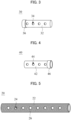
FIGS. 3 and 4 are schematic perspective views of a first sub-unit and a second sub-unit, respectively, according to exemplary embodiments. -
FIG. 5 is a schematic perspective view of a second unit according to exemplary embodiments; -
FIG. 6 is a perspective view schematically illustrating a construction in which a second unit is inserted into a first unit according to exemplary embodiments. -
FIG. 7 is a perspective view schematically illustrating a construction in which a first sub-unit and a second sub-unit are inserted into a second unit according to exemplary embodiments. -
FIG. 8 is a diagram schematically illustrating a mechanism for opening an enclosed space formed by a second unit, a first sub-unit and a second sub-unit according to exemplary embodiments. -
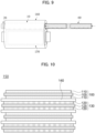
FIG. 9 is a diagram schematically illustrating a mechanism for replacing a second unit to a second sub-unit according to exemplary embodiments. -
FIG. 10 is a schematic cross-sectional view of an electrode assembly according to exemplary embodiments. - Hereinafter, the present invention will be described in detail with reference to the accompanying drawings. However, those skilled in the art will appreciate that such embodiments described with reference to the accompanying drawings are provided to further understand the spirit of the present invention and do not limit subject matters to be protected as disclosed in the detailed description and appended claims.
- Referring to
FIG. 1 , a lithium secondary battery 1 includes anelectrode assembly 150; an electrolyte (not illustrated) impregnating theelectrode assembly 150; anelectrolyte storage unit 5 containing a supplementary electrolyte; and acase 160 accommodating theelectrode assembly 150, the electrolyte and theelectrolyte storage unit 5. For example, theelectrolyte storage unit 5 may be inserted into thecase 160 to be adjacent to theelectrode assembly 150. - For example, the
case 160 may include afirst space 172 accommodating theelectrode assembly 150 and the electrolyte impregnating theelectrode assembly 150; and asecond space 174 into which theelectrolyte storage unit 5 is inserted. - In an embodiment, as illustrated in
FIG. 1 , a longitudinal direction of theelectrode assembly 150 and a longitudinal direction of theelectrolyte storage unit 5 may be parallel to each other. - For example, the longitudinal direction of the
electrode assembly 150 may refer to a direction parallel to a long side direction of a cathode (or an anode). - For example, the longitudinal direction of the
electrolyte storage unit 5 may refer to a direction parallel to a direction in which theelectrolyte storage unit 5 is inserted into thecase 160. For example, a longitudinal direction of thefirst unit 10, a longitudinal direction of asecond unit 20, and a longitudinal direction of sub-units (a first sub-unit and a second sub-unit) described later may refer to a direction parallel to the direction in which theelectrolyte storage unit 5 is inserted into thecase 160. - In an embodiment, the
second space 174 may extend in the longitudinal direction of theelectrode assembly 150. In an embodiment, a length of theelectrode assembly 150 in the longitudinal direction and a length of theelectrolyte storage unit 5 in the longitudinal direction may be equivalent to each other. - For example, the
case 160 may further include apassage portion 176 between thefirst space 172 and thesecond space 174. For example, the supplementary electrolyte accommodated in theelectrolyte storage unit 5 may be transferred from thesecond space 174 to thefirst space 172. - In an embodiment, the
case 160 may include a sealing portion and a non-sealing portion at an outer peripheral portion. For example, thecase 160 may include three sealingportions non-sealing portion 168. For example, thenon-sealing portion 168 may be formed by folding one sheet. - For example, the
first space 172 may include an enclosed space. For example, thesecond space 174 may include an enclosed space or a space in which at least one side is open. - For example, an outer surface of the electrolyte storage unit 5 (e.g., an outer surface of the first unit) may be in a close contact with an inner surface of the
second space 174 so that the supplementary electrolyte may not be leaked to an outside of thecase 160. - The
electrolyte storage unit 5 may include afirst unit 10 and a sub-unit inserted into thefirst unit 10 . - Referring to
FIG. 2 , thefirst unit 10 may include afirst body 12 having a tubular structure andfirst holes 14 formed in thefirst body 12. For example, thefirst body 12 may have a tubular structure in which both ends are open. For example, at least one of thefirst holes 14 may be connected to thepassage portion 176 . - In some embodiments, the
first holes 14 may be formed in a line or in series in thefirst body 12 along the longitudinal direction of thefirst unit 10 . - The sub-unit includes a body having a tubular structure (hereinafter, abbreviated as a tubular body) and sub-holes formed in the tubular body. The sub-unit may be inserted into the
first unit 10 such that the sub-holes may be offset from or may not overlap the first holes 14. Accordingly, an enclosed space may be formed in thefirst unit 10 and the sub-unit. The supplementary electrolyte may be accommodated in the enclosed space. - In some embodiments, the sub-holes may be formed in a line or in series in the tubular body along the longitudinal direction of the sub-unit.
- Referring to
FIGS. 3 and 4 , the sub-unit may include afirst sub-unit 30 and asecond sub-unit 40. For example, thefirst sub-unit 30 and thesecond sub-unit 40 may each be inserted into both ends of thefirst unit 10. - In some embodiments, the
first sub-unit 30 and thesecond sub-unit 40 may be disposed in thefirst unit 10 to be spaced apart from each other in the longitudinal direction of thefirst unit 10. - The
first sub-unit 30 may include a firsttubular body 32 and first sub-holes 34 formed in the firsttubular body 32. For example, the firsttubular body 32 may have a tubular structure in which one end is closed and the other end (an end opposite to the one end in the longitudinal direction) is opened. - In some embodiments, the first sub-holes 34 may be formed in a line or in series in the first
tubular body 32 along the longitudinal direction of thefirst sub-unit 30. - The
second sub-unit 40 may include a secondtubular body 42 and second sub-holes 44 formed in the secondtubular body 42. For example, the secondtubular body 42 may have a tubular structure in which one end is closed and the other end is opened. - In some embodiments, the second sub-holes 44 may be formed in a line or in series in the second
tubular body 42 along the longitudinal direction of thesecond sub-unit 40. - Referring to
FIG. 5 , in an embodiment, theelectrolyte storage unit 5 may further include asecond unit 20 inserted between thefirst unit 10 and the sub-units. - The
second unit 20 may include asecond body 22 having a tubular structure andsecond holes 24 formed in thesecond body 22. For example, thesecond body 22 may have a tubular structure in which both ends are opened. - In some embodiments, the
second holes 24 may be formed in a line or in series in thesecond body 22 along the longitudinal direction of thesecond unit 20. - Referring to
FIG. 6 , thesecond unit 20 may be inserted into thefirst unit 10 such that at least one of thesecond holes 24 overlaps at least one of the first holes 14. The sub-units 30 and 40 (not illustrated inFIG. 6 ) may be inserted into thesecond unit 20. Accordingly, thesecond unit 20 may be disposed between thefirst unit 10 and the sub-unit. - In some embodiments, as illustrated in
FIG. 6 , thefirst unit 10 and thesecond unit 20 may include the same number of holes. For example, thefirst holes 14 and thesecond holes 24 may be disposed to overlap each other. - Referring to
FIG. 7 , thefirst sub-unit 30 and thesecond sub-unit 40 may be inserted into thesecond unit 20. For example, thefirst sub-unit 30 and thesecond sub-unit 40 may each be inserted from both ends of thesecond unit 10. For example, thefirst sub-unit 30 and thesecond sub-unit 40 may be disposed in thesecond unit 20 to be spaced apart from each other in the longitudinal direction of thesecond unit 20. - In some embodiments, the
first holes 14, thesecond holes 24, the first sub-holes 34 and the second sub-holes 44 may be arranged in a line or in series along the longitudinal direction of thefirst unit 10. - For example, the enclosed one end of the
first sub-unit 30 and the enclosed one end of thesecond sub-unit 40 may be disposed to face the outside of thecase 160. For example, thesecond holes 24, the first sub-holes 34 and the second sub-holes 44 may be offset from each other. Accordingly, anenclosed space 50 may be formed in thesecond unit 20, thefirst sub-unit 30 and thesecond sub-unit 40. The supplementary electrolyte may be accommodated in the enclosedspace 50 . - In an embodiment, as illustrated in
FIG. 3 , thefirst sub-unit 30 may include afirst packing unit 36 coupled to one end portion thereof. In some embodiments, thefirst packing unit 36 may be disposed on an outer surface of the closed one end portion of the firsttubular body 32. For example, thefirst packing portion 36 may be disposed between thesecond unit 20 and thefirst sub-unit 30. An airtightness of the enclosedspace 50 may be improved by thefirst packing unit 36. - In some embodiments, the
first packing unit 36 may surround an outer surface of the enclosed one end portion of the firsttubular body 32. - In an embodiment, as illustrated in
FIG. 4 , thesecond sub-unit 40 may include asecond packing unit 46 coupled to one end portion thereof. In some embodiments, thesecond packing unit 46 may be disposed on an outer surface of the closed one end portion of the secondtubular body 42. For example, thesecond packing unit 46 may be disposed between thesecond unit 20 and thesecond sub-unit 40. An airtightness of the enclosedspace 50 may be improved by thesecond packing unit 46. - In some embodiments, the
second packing unit 46 may surround an outer surface of the closed one end portion of the secondtubular body 42. - In some embodiments, each of the
first sub-unit 30 and thesecond sub-unit 40 may have a packing unit coupled to an end portion opposite to the one end portion (i.e., the other end portion). Accordingly, the airtightness of the closedspace 50 may be further improved. - In an embodiment, the packing unit may include an elastic material. In some embodiments, the elastic material may include a natural rubber, a synthetic rubber or an elastomer.
- For example, the elastomer may include a polyolefin-based elastomer, a urethane-based elastomer, a styrene-based block copolymer, a vinyl chloride elastomer, a chlorinated polyethylene elastomer, a polyester-based elastomer, a polyamide-based elastomer, a fluorine-based elastomer, silicone-based elastomers, etc. Preferably, a material having chemical resistance to the electrolyte may be used.
- In an embodiment, the material of the packing unit may include the polyolefin-based resin. For example, the polyolefin-based resin may include polyethylene, etc.
- For example, when the lithium secondary battery 1 is repeatedly charged and discharged, at least a portion of the electrolyte contained in the
first space 172 may be consumed. - In an embodiment, at least one of the
first sub-unit 30 and thesecond sub-unit 40 may be movable at an inside of thefirst unit 10 in a direction in which a volume of the enclosedspace 50 is reduced by an external force (e.g., the longitudinal direction of the first unit). - For example, as the
first sub-unit 30 moves, at least one of the first sub-holes 34 is arranged to overlap at least one of thefirst holes 14 so that theenclosed space 50 may be opened. For example, as thesecond sub-unit 40 moves, at least one of the second sub-holes 44 is arranged to overlap at least one of thefirst holes 14 so that theenclosed space 50 may be opened. - For example, the supplementary electrolyte may flow through at least one of the first sub-holes 34 and the second sub-holes 44, at least one of the
first holes 14, and thepassage portion 176 to be discharged into thefirst space 172. - Hereinafter, an electrolyte replenishing mechanism according to exemplary embodiments will be described in more detail with reference to
FIG. 8 - Referring to (A) of
FIG. 8 , the enclosed one end portion of thefirst sub-unit 30 and the enclosed one end portion of thesecond sub-unit 40 may each be disposed to face the outside of thecase 160. The second holes 24, the first sub-holes 34 and the second sub-holes 44 may be arranged to be offset from each other, so that theenclosed space 50 may be formed in thesecond unit 20, thefirst sub-unit 30 and thesecond sub-unit 40. The supplementary electrolyte may be accommodated in the enclosedspace 50. - Referring to (B) of
FIG. 8 , thefirst sub-unit 30 and thesecond sub-unit 40 may be moved at an inside of thesecond unit 20 in a direction in which a volume of the enclosedspace 50 is reduced by an external force (e.g., the longitudinal direction of the second unit). Accordingly, thesecond holes 24 and at least one of the first sub-holes 34 and the second sub-holes 44 may overlap each other. Thus, theenclosed space 50 may be opened. - As illustrated in
FIG. 6 , thefirst holes 14 and thesecond holes 24 may overlap each other. Thus, when theenclosed space 50 is opened, the supplementary electrolyte may be moved to thefirst space 172 through thefirst holes 14 and thepassage portion 176. - As described above, in the lithium secondary battery according to embodiments of the present invention, the electrolyte may be replenished while maintaining the airtightness of the
first space 172. Accordingly, damages to the lithium secondary battery due to a permeation of external air and moisture when replenishing the electrolyte may be prevented. - Referring again to
FIG. 1 , in some embodiments, thepassage portion 176 may include asealing line portion 178. Accordingly, the airtightness of thefirst space 172 may be further improved. For example, the sealingline portion 178 may be opened by a discharging pressure of the supplementary electrolyte. - In an embodiment, the
first unit 10 may have a first coefficient of thermal expansion, and thesecond unit 20 may have a second coefficient of thermal expansion different from the first coefficient of thermal expansion. For example, the coefficient of thermal expansion may be a linear expansion coefficient. - For example, if the
electrolyte storage unit 5 may be exposed to a temperature equal to or lower than a predetermined temperature (e.g., -20°C or less, preferably -30°C or less) or higher than a predetermined temperature (e.g., 40°C or higher, preferably 50°C or higher). ), a gap may be generated between thefirst unit 10 and thesecond unit 20. For example, the gap may be formed between thefirst unit 10 and thesecond unit 20 by cooling or heating theelectrolyte storage unit 5 to the predetermined temperature. - For example, the
second unit 20 may be physically separated from thefirst unit 10 by the gap. For example, the gap may not be formed at room temperature, and thus thesecond unit 20 may not be physically separated from thefirst unit 10 without damaging thefirst unit 10. For example, the sub-unit may also be separated from thefirst unit 10 together with thesecond unit 20. - In some embodiments, the
second unit 20 may be physically separated from thefirst unit 10 at a temperature ranging from -30°C to -20°C. - In some embodiments, the
second unit 20 may be physically separated from thefirst unit 10 at a temperature ranging 40°C to 50°C. - In an embodiment, a gap may be formed between the
first unit 10 and thesecond unit 20 in which the supplementary electrolyte is consumed, so that thesecond unit 20 in which the supplementary electrolyte is consumed and the sub-unit may be separated from thefirst unit 10. The supplementary electrolyte may be newly charged in thesecond unit 20 where the supplementary electrolyte is consumed, and thesecond unit 20 may be inserted again into thefirst unit 10. In this case, the sealingline portion 178 may be reformed to maintain the airtightness of thefirst space 172. - Referring to
FIG. 9 , in an embodiment, areplacement unit 60 including thesecond unit 20 filled with the supplementary electrolyte and the sub-unit may be additionally prepared and inserted into thefirst unit 10. - In exemplary embodiments, a gap may be formed between the
first unit 10 and thesecond unit 20 in which the supplementary electrolyte is consumed. Thereplacement unit 60 may be inserted into thefirst unit 10, and thesecond unit 20 in which the supplementary electrolyte is consumed may be separated by being pushed from thefirst unit 10. The sub-unit may be separated from thefirst unit 10 together with thesecond unit 20. In this case, the replacement may be performed while maintaining the airtightness of thefirst space 172. - In some embodiments, the replacement may be performed under a low-temperature condition (e.g., -20°C or less, or -30°C or less) or a high-temperature condition (e.g., 40°C or higher, or 50°C or higher). Preferably, the replacement may be performed under the low-temperature condition. In this case, deformation of the electrolyte under the high temperature condition may be avoided.
- In some embodiments, an absolute difference between the first coefficient of thermal expansion and the second coefficient of thermal expansion may be 5 µm/K or more, 10 µm/K or more, or 20 µm/K or more. Within the above range, the separation may be implemented without deterioration of the lithium secondary battery.
- In some embodiments, the absolute difference between the first coefficient of thermal expansion and the second coefficient of thermal expansion may be 50 µm/K or less, 40 µm/K or less, or 30 µm/K or less. Within the above range, the airtightness of the
first space 172 may be improved. Within this range, penetration of external air and moisture into thefirst space 172 during the separation process may be effectively prevented. - A high-temperature environment may be created by a heat generation during repeated charging and discharging of the lithium secondary battery. In some embodiments, the second coefficient of thermal expansion may be greater than the first coefficient of thermal expansion. In this case, the gap between the
first unit 10 and thesecond unit 20 may be formed at a low temperature, and the gap may not be formed at a high temperature. Accordingly, high-temperature durability of theelectrolyte storage unit 5 may be improved. - In some embodiments, each of the
first unit 10 and thesecond unit 20 may be formed of a metal such as stainless steel, copper, zinc, aluminum, manganese, tungsten, molybdenum, nickel, iron, silver, etc.; a polymer such as EP (Engineering plastic) and PET; and a ceramic such as Al2O3 and TiO2. These may be used alone or in combination thereof - In some embodiments, the
first unit 10 may include stainless steel and thesecond unit 20 may include aluminum. - For example, the
first unit 10, thesecond unit 20 and the sub-unit may include a material that may have a chemical resistance to the supplementary electrolyte (e.g., that nay not cause a side reaction with the supplementary electrolyte). - In some embodiments, the sub-unit may include a metal such as stainless steel, copper, zinc, aluminum, manganese, tungsten, molybdenum, nickel, iron, silver, etc.; a polymer such as EP (Engineering plastic) and PET; and a ceramic such as Al2O3 and TiO2. These may be used alone or in combination thereof.
- In some embodiments, the sub-unit may include stainless steel, aluminum, etc.
- In some embodiments, an inner surface of the
first body 12 and an outer surface of thesecond body 22 may includescrew structures space 50 may be further improved. - In some embodiments, the
second space 174 may be formed at thenon-sealing portion 168. Accordingly, theelectrolyte storage unit 5 may be easily attached and inserted to thesecond space 174. In addition, durability against repeated attachment and detachment of thesecond unit 20 and thesecond sub-unit 40 may be obtained. - Referring to
FIG. 10 , theelectrode assembly 150 may include acathode 100 and ananode 130 facing thecathode 100 . - For example, the
cathode 100 may include a cathodecurrent collector 105 and a cathodeactive material layer 110 on the cathodecurrent collector 105. - For example, the cathode
active material layer 110 includes a cathode active material, and may further include a cathode binder and a conductive material. - For example, the cathode
current collector 105 may include stainless steel, nickel, aluminum, titanium, copper, or an alloy thereof. - For example, the cathode active material may include a material capable of reversibly intercalating and de-intercalating lithium ions. For example, the cathode active material may include lithium metal oxide particles. For example, materials widely known in the related art may be used as the cathode binder and the conductive material without a particular limitation.
- For example, the
anode 130 may include an anodecurrent collector 125 and an anodeactive material layer 120 on the anodecurrent collector 125 . - For example, the anode
active material layer 120 includes an anode active material, and may further include an anode binder and a conductive material. - For example, the anode
current collector 125 may include gold, stainless steel, nickel, aluminum, titanium, copper, or an alloy thereof. - For example, the anode active material may be a material capable of adsorbing and desorbing lithium ions. For example, the anode active material may include a lithium alloy, a carbon-based active material, a silicon-based active material, etc. For example, the anode binder and the conductive material widely known in the related art may be used without a particular limitation.
- In some embodiments, a
separation layer 140 may be interposed between theanode 100 and thecathode 130. For example, theseparation layer 140 may include a material widely known in the related art without a particular limitation. - For example, the
electrode assembly 150 may be formed by alternately and repeatedly stacking thecathode 100, theanode 130 and theseparation layer 140. For example, theelectrode assembly 150 may be formed by winding, lamination or z-folding of theseparation layer 140. - Referring again to
FIG. 1 , the lithium secondary battery according to exemplary embodiments includes acathode lead 107 connected to thecathode 100 and protruding to the outside of acase 160; and ananode lead 127 connected to theanode 130 and protruding to the outside of thecase 160 . - For example, the
cathode 100 and thecathode lead 107 may be electrically connected. Theanode 130 and theanode lead 127 may be electrically connected. - For example, the
cathode lead 107 may be electrically connected to the cathodecurrent collector 105. Theanode lead 127 may be electrically connected to the anodecurrent collector 125. - For example, the cathode
current collector 105 may include a cathode tab protruding at one side thereof. The cathodeactive material layer 110 may not be formed on thecathode tab 106. Thecathode tab 106 may be integral with the cathodecurrent collector 105 or may be connected to the cathodecurrent collector 105 by, e.g., welding. The cathodecurrent collector 105 and thecathode lead 107 may be electrically connected via thecathode tab 106. - The anode
current collector 125 may include ananode tab 126 protruding at one side thereof. The anodeactive material layer 120 may not be formed on theanode tab 126. Theanode tab 126 may be integral with the anodecurrent collector 125 or may be connected to the anodecurrent collector 125 by, e.g., welding. The anode electrodecurrent collector 125 and theanode lead 127 may be electrically connected via the anode tab. - For example, the
electrode assembly 150 may include a plurality of the cathodes and a plurality of the anodes. For example, each of the plurality of the cathodes may include the cathode tab, and each of the plurality of the anodes may include the anode tab. - For example, the cathode tabs (or the anode tabs) may be laminated, pressed and welded to form a cathode tab stack (or an anode tab stack). The cathode tab stack may be electrically connected to the
cathode lead 107. The anode tab stack may be electrically connected to theanode lead 127. - For example, the electrolyte solution and the supplementary electrolyte may include a lithium salt, an organic solvent, and may optionally further include an additive. For example, materials widely known in the related art may be used as the lithium salt, the organic solvent and the additive without a particular limitation.
Claims (15)
- A lithium secondary battery, comprising:an electrode assembly including a cathode and an anode facing the cathode;a case accommodating the electrode assembly;an electrolyte accommodated in the case together with the electrode assembly; andan electrolyte storage unit inserted into the case to supply a supplementary electrolyte,wherein the electrolyte storage unit comprises:a first unit comprising a first body having a tubular structure and first holes formed through the first body; anda sub-unit comprising a tubular body and sub-holes formed through the tubular body, wherein the sub-unit is inserted into the first unit so that the sub-holes are offset from the first holes.
- The lithium secondary battery according to claim 1, wherein the electrolyte storage unit further comprises a second unit that comprises a second body having a tubular structure and second holes formed through the second body, and
the second unit is inserted between the first unit and the sub-unit so that at least one of the second holes overlaps at least one of the first holes, preferably wherein the second holes are arranged to be offset from the sub-holes. - The lithium secondary battery according to claim 2, wherein an inner surface of the first body and an outer surface of the second body have screw structures to be fastened to each other.
- The lithium secondary battery according to claim 2 or 3, wherein the first unit has a first coefficient of thermal expansion, and the second unit has a second coefficient of thermal expansion different from the first coefficient of thermal expansion.
- The lithium secondary battery according to claim 4, wherein the second coefficient of thermal expansion is greater than the first coefficient of thermal expansion.
- The lithium secondary battery according to one of claims 2 to 5, wherein the second unit is physically separable from the first unit at a temperature of -20°C or less, or 40°C or higher.
- The lithium secondary battery according to one of claims 1-6, wherein the sub-unit comprises a first sub-unit and a second sub-unit which are inserted into both end portions of the first unit.
- The lithium secondary battery according to claim 7, wherein the electrolyte storage unit further comprises:a first packing unit coupled to one end portion of the first sub-unit; anda second packing unit coupled to one end portion of the second sub-unit.
- The lithium secondary battery according to claim 7 or 8, wherein the first sub-unit and the second sub-unit are disposed in the first unit to be spaced apart from each other in a longitudinal direction of the first unit.
- The lithium secondary battery according to one of claims 7 to 9, wherein the first sub-unit and the second sub-unit are movable by an external force in the longitudinal direction so that at least one of the sub-holes overlaps at least one of the first holes.
- The lithium secondary battery according to one of claims 1-10, wherein the case comprises:a first space accommodating the electrode assembly and the electrolyte;a second space into which the electrolyte storage unit is inserted; anda passage portion through which the supplementary electrolyte is capable of being transferred between the first space and the second space.
- The lithium secondary battery of claim 11, wherein the second space extend in a longitudinal direction of the electrode assembly.
- The lithium secondary battery according to claim 11 or 12, wherein the passage portion comprises a sealing line portion that is capable of being opened by a pressure due to a discharge of the supplementary electrolyte.
- A method of replenishing an electrolyte in a lithium secondary battery, comprising:preparing the lithium secondary battery according to one of claims 1 to 13; anddischarging the supplementary electrolyte from the electrolyte storage unit to a peripheral portion of the electrode assembly when at least a portion of the electrolyte is consumed.
- The method according to claim 14, wherein the method further comprises:cooling or heating the lithium secondary battery to form a gap between the first unit and the second unit in the electrolyte storage unit from which the supplementary electrolyte is discharged;preparing a replacement unit that comprises a second unit and a sub-unit filled with a supplementary electrolyte; andinserting the replacement unit filled with the supplementary electrolyte into the first unit to separate the second unit and the sub-unit from which the supplementary electrolyte is discharged from the first unit.
Applications Claiming Priority (1)
| Application Number | Priority Date | Filing Date | Title |
|---|---|---|---|
| KR1020210179642A KR20230090675A (en) | 2021-12-15 | 2021-12-15 | Lithium secondary battery |
Publications (2)
| Publication Number | Publication Date |
|---|---|
| EP4203175A1 true EP4203175A1 (en) | 2023-06-28 |
| EP4203175B1 EP4203175B1 (en) | 2024-07-03 |
Family
ID=84535726
Family Applications (1)
| Application Number | Title | Priority Date | Filing Date |
|---|---|---|---|
| EP22213388.6A Active EP4203175B1 (en) | 2021-12-15 | 2022-12-14 | Lithium secondary battery and method of replenishing electrolyte in lithium secondary battery |
Country Status (4)
| Country | Link |
|---|---|
| US (1) | US12592463B2 (en) |
| EP (1) | EP4203175B1 (en) |
| KR (1) | KR20230090675A (en) |
| CN (1) | CN116264319A (en) |
Families Citing this family (1)
| Publication number | Priority date | Publication date | Assignee | Title |
|---|---|---|---|---|
| CN119231127A (en) * | 2023-06-30 | 2024-12-31 | 厦门海辰储能科技股份有限公司 | Energy storage devices and electrical equipment |
Citations (4)
| Publication number | Priority date | Publication date | Assignee | Title |
|---|---|---|---|---|
| JP2009076248A (en) * | 2007-09-19 | 2009-04-09 | Fuji Heavy Ind Ltd | Electric storage device and manufacturing method thereof |
| KR20110132856A (en) | 2010-06-03 | 2011-12-09 | 삼성에스디아이 주식회사 | Method of injecting electrolyte solution for secondary battery and secondary battery |
| US20140154554A1 (en) * | 2011-08-24 | 2014-06-05 | Sk Innovation Co.,Ltd. | Battery module |
| US20150287548A1 (en) * | 2012-06-28 | 2015-10-08 | Evonik Litarion Gmbh | Self-limiting electrolyte filling method |
Family Cites Families (5)
| Publication number | Priority date | Publication date | Assignee | Title |
|---|---|---|---|---|
| US6955187B1 (en) | 2003-07-16 | 2005-10-18 | Tini Alloy Company | Zinc-air battery control valve |
| KR101245284B1 (en) | 2010-12-20 | 2013-03-19 | 주식회사 엘지화학 | Secondary battery capable of re-injecting electrolyte |
| KR101651515B1 (en) | 2011-10-10 | 2016-08-29 | 주식회사 엘지화학 | Secondary battery with automatic electrolyte supplementing function |
| KR102334022B1 (en) | 2018-11-02 | 2021-12-02 | 주식회사 엘지에너지솔루션 | Pouch-type Secondary Battery Having Groove for Replenishing an electrolyte |
| KR102752406B1 (en) | 2019-02-20 | 2025-01-10 | 에스케이온 주식회사 | Secondary battery with additional structures that can improve long term characteristics and manufacturing method thereof |
-
2021
- 2021-12-15 KR KR1020210179642A patent/KR20230090675A/en active Pending
-
2022
- 2022-12-09 US US18/063,750 patent/US12592463B2/en active Active
- 2022-12-14 CN CN202211606466.7A patent/CN116264319A/en active Pending
- 2022-12-14 EP EP22213388.6A patent/EP4203175B1/en active Active
Patent Citations (4)
| Publication number | Priority date | Publication date | Assignee | Title |
|---|---|---|---|---|
| JP2009076248A (en) * | 2007-09-19 | 2009-04-09 | Fuji Heavy Ind Ltd | Electric storage device and manufacturing method thereof |
| KR20110132856A (en) | 2010-06-03 | 2011-12-09 | 삼성에스디아이 주식회사 | Method of injecting electrolyte solution for secondary battery and secondary battery |
| US20140154554A1 (en) * | 2011-08-24 | 2014-06-05 | Sk Innovation Co.,Ltd. | Battery module |
| US20150287548A1 (en) * | 2012-06-28 | 2015-10-08 | Evonik Litarion Gmbh | Self-limiting electrolyte filling method |
Also Published As
| Publication number | Publication date |
|---|---|
| EP4203175B1 (en) | 2024-07-03 |
| KR20230090675A (en) | 2023-06-22 |
| US12592463B2 (en) | 2026-03-31 |
| CN116264319A (en) | 2023-06-16 |
| US20230187797A1 (en) | 2023-06-15 |
Similar Documents
| Publication | Publication Date | Title |
|---|---|---|
| US11296361B2 (en) | Bipolar battery design | |
| KR100477750B1 (en) | Electorde assembly for lithium ion cell and lithium ion cell using the same | |
| CN110024179B (en) | Pouch Type Secondary Battery | |
| KR100614381B1 (en) | Lithium ion secondary battery | |
| JP6750390B2 (en) | Bipolar battery | |
| KR101999529B1 (en) | Pouch-Type Secondary Battery Having Electrode Lead with Couple Notch | |
| JP7670795B2 (en) | Optimized temperature regulation battery | |
| JP2014529855A (en) | Battery module | |
| KR100786875B1 (en) | Battery module | |
| JP2003187855A (en) | Manufacturing method of secondary battery | |
| EP4203175B1 (en) | Lithium secondary battery and method of replenishing electrolyte in lithium secondary battery | |
| EP4203176B1 (en) | Battery module | |
| US11721839B2 (en) | Electrode assembly with improved connection between electrode tabs | |
| CN110690408B (en) | Cells and their batteries | |
| US20080220326A1 (en) | Battery module and method of manufacturing the same | |
| JP2006080066A (en) | Lithium ion secondary battery | |
| KR101596489B1 (en) | Pouch for Secondary Cell, Pouch Type Secondary Cell and Device Comprising the Same Having Long-life Efficiency | |
| US12374734B2 (en) | Battery cell with internal swelling relief and external cooling features | |
| KR20040005242A (en) | Jelly-roll type battery unit forming short prevention means and the lithium secondary battery applying the same | |
| KR102930968B1 (en) | The Secondary Battery And The Battery Module | |
| KR100502354B1 (en) | Pouched-type lithium secondary battery | |
| GB2590392A (en) | A battery cell with internal swelling relief and external cooling features | |
| KR101256062B1 (en) | Rechargeable battery | |
| KR20070025686A (en) | Lithium secondary battery | |
| US20110117429A1 (en) | Galvanic cell with improved lifetime |
Legal Events
| Date | Code | Title | Description |
|---|---|---|---|
| PUAI | Public reference made under article 153(3) epc to a published international application that has entered the european phase |
Free format text: ORIGINAL CODE: 0009012 |
|
| STAA | Information on the status of an ep patent application or granted ep patent |
Free format text: STATUS: REQUEST FOR EXAMINATION WAS MADE |
|
| 17P | Request for examination filed |
Effective date: 20221214 |
|
| AK | Designated contracting states |
Kind code of ref document: A1 Designated state(s): AL AT BE BG CH CY CZ DE DK EE ES FI FR GB GR HR HU IE IS IT LI LT LU LV MC ME MK MT NL NO PL PT RO RS SE SI SK SM TR |
|
| GRAP | Despatch of communication of intention to grant a patent |
Free format text: ORIGINAL CODE: EPIDOSNIGR1 |
|
| STAA | Information on the status of an ep patent application or granted ep patent |
Free format text: STATUS: GRANT OF PATENT IS INTENDED |
|
| INTG | Intention to grant announced |
Effective date: 20240213 |
|
| GRAS | Grant fee paid |
Free format text: ORIGINAL CODE: EPIDOSNIGR3 |
|
| GRAA | (expected) grant |
Free format text: ORIGINAL CODE: 0009210 |
|
| STAA | Information on the status of an ep patent application or granted ep patent |
Free format text: STATUS: THE PATENT HAS BEEN GRANTED |
|
| AK | Designated contracting states |
Kind code of ref document: B1 Designated state(s): AL AT BE BG CH CY CZ DE DK EE ES FI FR GB GR HR HU IE IS IT LI LT LU LV MC ME MK MT NL NO PL PT RO RS SE SI SK SM TR |
|
| REG | Reference to a national code |
Ref country code: CH Ref legal event code: EP |
|
| REG | Reference to a national code |
Ref country code: DE Ref legal event code: R096 Ref document number: 602022004337 Country of ref document: DE |
|
| REG | Reference to a national code |
Ref country code: LT Ref legal event code: MG9D |
|
| REG | Reference to a national code |
Ref country code: NL Ref legal event code: MP Effective date: 20240703 |
|
| PG25 | Lapsed in a contracting state [announced via postgrant information from national office to epo] |
Ref country code: PT Free format text: LAPSE BECAUSE OF FAILURE TO SUBMIT A TRANSLATION OF THE DESCRIPTION OR TO PAY THE FEE WITHIN THE PRESCRIBED TIME-LIMIT Effective date: 20241104 |
|
| REG | Reference to a national code |
Ref country code: AT Ref legal event code: MK05 Ref document number: 1700806 Country of ref document: AT Kind code of ref document: T Effective date: 20240703 |
|
| PG25 | Lapsed in a contracting state [announced via postgrant information from national office to epo] |
Ref country code: NL Free format text: LAPSE BECAUSE OF FAILURE TO SUBMIT A TRANSLATION OF THE DESCRIPTION OR TO PAY THE FEE WITHIN THE PRESCRIBED TIME-LIMIT Effective date: 20240703 |
|
| PG25 | Lapsed in a contracting state [announced via postgrant information from national office to epo] |
Ref country code: PT Free format text: LAPSE BECAUSE OF FAILURE TO SUBMIT A TRANSLATION OF THE DESCRIPTION OR TO PAY THE FEE WITHIN THE PRESCRIBED TIME-LIMIT Effective date: 20241104 Ref country code: NL Free format text: LAPSE BECAUSE OF FAILURE TO SUBMIT A TRANSLATION OF THE DESCRIPTION OR TO PAY THE FEE WITHIN THE PRESCRIBED TIME-LIMIT Effective date: 20240703 |
|
| PG25 | Lapsed in a contracting state [announced via postgrant information from national office to epo] |
Ref country code: NO Free format text: LAPSE BECAUSE OF FAILURE TO SUBMIT A TRANSLATION OF THE DESCRIPTION OR TO PAY THE FEE WITHIN THE PRESCRIBED TIME-LIMIT Effective date: 20241003 |
|
| PG25 | Lapsed in a contracting state [announced via postgrant information from national office to epo] |
Ref country code: FI Free format text: LAPSE BECAUSE OF FAILURE TO SUBMIT A TRANSLATION OF THE DESCRIPTION OR TO PAY THE FEE WITHIN THE PRESCRIBED TIME-LIMIT Effective date: 20240703 Ref country code: GR Free format text: LAPSE BECAUSE OF FAILURE TO SUBMIT A TRANSLATION OF THE DESCRIPTION OR TO PAY THE FEE WITHIN THE PRESCRIBED TIME-LIMIT Effective date: 20241004 Ref country code: PL Free format text: LAPSE BECAUSE OF FAILURE TO SUBMIT A TRANSLATION OF THE DESCRIPTION OR TO PAY THE FEE WITHIN THE PRESCRIBED TIME-LIMIT Effective date: 20240703 |
|
| PG25 | Lapsed in a contracting state [announced via postgrant information from national office to epo] |
Ref country code: BG Free format text: LAPSE BECAUSE OF FAILURE TO SUBMIT A TRANSLATION OF THE DESCRIPTION OR TO PAY THE FEE WITHIN THE PRESCRIBED TIME-LIMIT Effective date: 20240703 |
|
| PG25 | Lapsed in a contracting state [announced via postgrant information from national office to epo] |
Ref country code: LV Free format text: LAPSE BECAUSE OF FAILURE TO SUBMIT A TRANSLATION OF THE DESCRIPTION OR TO PAY THE FEE WITHIN THE PRESCRIBED TIME-LIMIT Effective date: 20240703 |
|
| PG25 | Lapsed in a contracting state [announced via postgrant information from national office to epo] |
Ref country code: IS Free format text: LAPSE BECAUSE OF FAILURE TO SUBMIT A TRANSLATION OF THE DESCRIPTION OR TO PAY THE FEE WITHIN THE PRESCRIBED TIME-LIMIT Effective date: 20241103 Ref country code: AT Free format text: LAPSE BECAUSE OF FAILURE TO SUBMIT A TRANSLATION OF THE DESCRIPTION OR TO PAY THE FEE WITHIN THE PRESCRIBED TIME-LIMIT Effective date: 20240703 |
|
| PG25 | Lapsed in a contracting state [announced via postgrant information from national office to epo] |
Ref country code: HR Free format text: LAPSE BECAUSE OF FAILURE TO SUBMIT A TRANSLATION OF THE DESCRIPTION OR TO PAY THE FEE WITHIN THE PRESCRIBED TIME-LIMIT Effective date: 20240703 Ref country code: CZ Free format text: LAPSE BECAUSE OF FAILURE TO SUBMIT A TRANSLATION OF THE DESCRIPTION OR TO PAY THE FEE WITHIN THE PRESCRIBED TIME-LIMIT Effective date: 20240703 |
|
| PG25 | Lapsed in a contracting state [announced via postgrant information from national office to epo] |
Ref country code: RS Free format text: LAPSE BECAUSE OF FAILURE TO SUBMIT A TRANSLATION OF THE DESCRIPTION OR TO PAY THE FEE WITHIN THE PRESCRIBED TIME-LIMIT Effective date: 20241003 Ref country code: ES Free format text: LAPSE BECAUSE OF FAILURE TO SUBMIT A TRANSLATION OF THE DESCRIPTION OR TO PAY THE FEE WITHIN THE PRESCRIBED TIME-LIMIT Effective date: 20240703 |
|
| PG25 | Lapsed in a contracting state [announced via postgrant information from national office to epo] |
Ref country code: RS Free format text: LAPSE BECAUSE OF FAILURE TO SUBMIT A TRANSLATION OF THE DESCRIPTION OR TO PAY THE FEE WITHIN THE PRESCRIBED TIME-LIMIT Effective date: 20241003 Ref country code: PL Free format text: LAPSE BECAUSE OF FAILURE TO SUBMIT A TRANSLATION OF THE DESCRIPTION OR TO PAY THE FEE WITHIN THE PRESCRIBED TIME-LIMIT Effective date: 20240703 Ref country code: NO Free format text: LAPSE BECAUSE OF FAILURE TO SUBMIT A TRANSLATION OF THE DESCRIPTION OR TO PAY THE FEE WITHIN THE PRESCRIBED TIME-LIMIT Effective date: 20241003 Ref country code: LV Free format text: LAPSE BECAUSE OF FAILURE TO SUBMIT A TRANSLATION OF THE DESCRIPTION OR TO PAY THE FEE WITHIN THE PRESCRIBED TIME-LIMIT Effective date: 20240703 Ref country code: IS Free format text: LAPSE BECAUSE OF FAILURE TO SUBMIT A TRANSLATION OF THE DESCRIPTION OR TO PAY THE FEE WITHIN THE PRESCRIBED TIME-LIMIT Effective date: 20241103 Ref country code: HR Free format text: LAPSE BECAUSE OF FAILURE TO SUBMIT A TRANSLATION OF THE DESCRIPTION OR TO PAY THE FEE WITHIN THE PRESCRIBED TIME-LIMIT Effective date: 20240703 Ref country code: GR Free format text: LAPSE BECAUSE OF FAILURE TO SUBMIT A TRANSLATION OF THE DESCRIPTION OR TO PAY THE FEE WITHIN THE PRESCRIBED TIME-LIMIT Effective date: 20241004 Ref country code: FI Free format text: LAPSE BECAUSE OF FAILURE TO SUBMIT A TRANSLATION OF THE DESCRIPTION OR TO PAY THE FEE WITHIN THE PRESCRIBED TIME-LIMIT Effective date: 20240703 Ref country code: ES Free format text: LAPSE BECAUSE OF FAILURE TO SUBMIT A TRANSLATION OF THE DESCRIPTION OR TO PAY THE FEE WITHIN THE PRESCRIBED TIME-LIMIT Effective date: 20240703 Ref country code: CZ Free format text: LAPSE BECAUSE OF FAILURE TO SUBMIT A TRANSLATION OF THE DESCRIPTION OR TO PAY THE FEE WITHIN THE PRESCRIBED TIME-LIMIT Effective date: 20240703 Ref country code: BG Free format text: LAPSE BECAUSE OF FAILURE TO SUBMIT A TRANSLATION OF THE DESCRIPTION OR TO PAY THE FEE WITHIN THE PRESCRIBED TIME-LIMIT Effective date: 20240703 Ref country code: AT Free format text: LAPSE BECAUSE OF FAILURE TO SUBMIT A TRANSLATION OF THE DESCRIPTION OR TO PAY THE FEE WITHIN THE PRESCRIBED TIME-LIMIT Effective date: 20240703 |
|
| REG | Reference to a national code |
Ref country code: DE Ref legal event code: R097 Ref document number: 602022004337 Country of ref document: DE |
|
| PG25 | Lapsed in a contracting state [announced via postgrant information from national office to epo] |
Ref country code: DK Free format text: LAPSE BECAUSE OF FAILURE TO SUBMIT A TRANSLATION OF THE DESCRIPTION OR TO PAY THE FEE WITHIN THE PRESCRIBED TIME-LIMIT Effective date: 20240703 Ref country code: SM Free format text: LAPSE BECAUSE OF FAILURE TO SUBMIT A TRANSLATION OF THE DESCRIPTION OR TO PAY THE FEE WITHIN THE PRESCRIBED TIME-LIMIT Effective date: 20240703 Ref country code: RO Free format text: LAPSE BECAUSE OF FAILURE TO SUBMIT A TRANSLATION OF THE DESCRIPTION OR TO PAY THE FEE WITHIN THE PRESCRIBED TIME-LIMIT Effective date: 20240703 |
|
| PG25 | Lapsed in a contracting state [announced via postgrant information from national office to epo] |
Ref country code: EE Free format text: LAPSE BECAUSE OF FAILURE TO SUBMIT A TRANSLATION OF THE DESCRIPTION OR TO PAY THE FEE WITHIN THE PRESCRIBED TIME-LIMIT Effective date: 20240703 |
|
| PG25 | Lapsed in a contracting state [announced via postgrant information from national office to epo] |
Ref country code: IT Free format text: LAPSE BECAUSE OF FAILURE TO SUBMIT A TRANSLATION OF THE DESCRIPTION OR TO PAY THE FEE WITHIN THE PRESCRIBED TIME-LIMIT Effective date: 20240703 Ref country code: SK Free format text: LAPSE BECAUSE OF FAILURE TO SUBMIT A TRANSLATION OF THE DESCRIPTION OR TO PAY THE FEE WITHIN THE PRESCRIBED TIME-LIMIT Effective date: 20240703 |
|
| PLBE | No opposition filed within time limit |
Free format text: ORIGINAL CODE: 0009261 |
|
| STAA | Information on the status of an ep patent application or granted ep patent |
Free format text: STATUS: NO OPPOSITION FILED WITHIN TIME LIMIT |
|
| 26N | No opposition filed |
Effective date: 20250404 |
|
| PG25 | Lapsed in a contracting state [announced via postgrant information from national office to epo] |
Ref country code: MC Free format text: LAPSE BECAUSE OF FAILURE TO SUBMIT A TRANSLATION OF THE DESCRIPTION OR TO PAY THE FEE WITHIN THE PRESCRIBED TIME-LIMIT Effective date: 20240703 |
|
| PG25 | Lapsed in a contracting state [announced via postgrant information from national office to epo] |
Ref country code: LU Free format text: LAPSE BECAUSE OF NON-PAYMENT OF DUE FEES Effective date: 20241214 |
|
| PG25 | Lapsed in a contracting state [announced via postgrant information from national office to epo] |
Ref country code: SE Free format text: LAPSE BECAUSE OF FAILURE TO SUBMIT A TRANSLATION OF THE DESCRIPTION OR TO PAY THE FEE WITHIN THE PRESCRIBED TIME-LIMIT Effective date: 20240703 |
|
| REG | Reference to a national code |
Ref country code: BE Ref legal event code: MM Effective date: 20241231 |
|
| PG25 | Lapsed in a contracting state [announced via postgrant information from national office to epo] |
Ref country code: BE Free format text: LAPSE BECAUSE OF NON-PAYMENT OF DUE FEES Effective date: 20241231 |
|
| PGFP | Annual fee paid to national office [announced via postgrant information from national office to epo] |
Ref country code: FR Payment date: 20250925 Year of fee payment: 4 |
|
| PG25 | Lapsed in a contracting state [announced via postgrant information from national office to epo] |
Ref country code: IE Free format text: LAPSE BECAUSE OF NON-PAYMENT OF DUE FEES Effective date: 20241214 |
|
| PGFP | Annual fee paid to national office [announced via postgrant information from national office to epo] |
Ref country code: DE Payment date: 20250922 Year of fee payment: 4 |
|
| PG25 | Lapsed in a contracting state [announced via postgrant information from national office to epo] |
Ref country code: CY Free format text: LAPSE BECAUSE OF FAILURE TO SUBMIT A TRANSLATION OF THE DESCRIPTION OR TO PAY THE FEE WITHIN THE PRESCRIBED TIME-LIMIT Effective date: 20240703 |