EP4203161B1 - Battery cell and battery module including the same - Google Patents
Battery cell and battery module including the same Download PDFInfo
- Publication number
- EP4203161B1 EP4203161B1 EP22811622.4A EP22811622A EP4203161B1 EP 4203161 B1 EP4203161 B1 EP 4203161B1 EP 22811622 A EP22811622 A EP 22811622A EP 4203161 B1 EP4203161 B1 EP 4203161B1
- Authority
- EP
- European Patent Office
- Prior art keywords
- adhesive layer
- battery cell
- adhesive
- discharge unit
- gas discharge
- Prior art date
- Legal status (The legal status is an assumption and is not a legal conclusion. Google has not performed a legal analysis and makes no representation as to the accuracy of the status listed.)
- Active
Links
Images


Classifications
-
- H—ELECTRICITY
- H01—ELECTRIC ELEMENTS
- H01M—PROCESSES OR MEANS, e.g. BATTERIES, FOR THE DIRECT CONVERSION OF CHEMICAL ENERGY INTO ELECTRICAL ENERGY
- H01M50/00—Constructional details or processes of manufacture of the non-active parts of electrochemical cells other than fuel cells, e.g. hybrid cells
- H01M50/30—Arrangements for facilitating escape of gases
-
- H—ELECTRICITY
- H01—ELECTRIC ELEMENTS
- H01M—PROCESSES OR MEANS, e.g. BATTERIES, FOR THE DIRECT CONVERSION OF CHEMICAL ENERGY INTO ELECTRICAL ENERGY
- H01M50/00—Constructional details or processes of manufacture of the non-active parts of electrochemical cells other than fuel cells, e.g. hybrid cells
- H01M50/10—Primary casings; Jackets or wrappings
- H01M50/183—Sealing members
- H01M50/19—Sealing members characterised by the material
- H01M50/193—Organic material
-
- H—ELECTRICITY
- H01—ELECTRIC ELEMENTS
- H01M—PROCESSES OR MEANS, e.g. BATTERIES, FOR THE DIRECT CONVERSION OF CHEMICAL ENERGY INTO ELECTRICAL ENERGY
- H01M10/00—Secondary cells; Manufacture thereof
- H01M10/05—Accumulators with non-aqueous electrolyte
- H01M10/052—Li-accumulators
-
- H—ELECTRICITY
- H01—ELECTRIC ELEMENTS
- H01M—PROCESSES OR MEANS, e.g. BATTERIES, FOR THE DIRECT CONVERSION OF CHEMICAL ENERGY INTO ELECTRICAL ENERGY
- H01M50/00—Constructional details or processes of manufacture of the non-active parts of electrochemical cells other than fuel cells, e.g. hybrid cells
- H01M50/10—Primary casings; Jackets or wrappings
- H01M50/102—Primary casings; Jackets or wrappings characterised by their shape or physical structure
- H01M50/103—Primary casings; Jackets or wrappings characterised by their shape or physical structure prismatic or rectangular
-
- H—ELECTRICITY
- H01—ELECTRIC ELEMENTS
- H01M—PROCESSES OR MEANS, e.g. BATTERIES, FOR THE DIRECT CONVERSION OF CHEMICAL ENERGY INTO ELECTRICAL ENERGY
- H01M50/00—Constructional details or processes of manufacture of the non-active parts of electrochemical cells other than fuel cells, e.g. hybrid cells
- H01M50/10—Primary casings; Jackets or wrappings
- H01M50/102—Primary casings; Jackets or wrappings characterised by their shape or physical structure
- H01M50/105—Pouches or flexible bags
-
- H—ELECTRICITY
- H01—ELECTRIC ELEMENTS
- H01M—PROCESSES OR MEANS, e.g. BATTERIES, FOR THE DIRECT CONVERSION OF CHEMICAL ENERGY INTO ELECTRICAL ENERGY
- H01M50/00—Constructional details or processes of manufacture of the non-active parts of electrochemical cells other than fuel cells, e.g. hybrid cells
- H01M50/10—Primary casings; Jackets or wrappings
- H01M50/172—Arrangements of electric connectors penetrating the casing
- H01M50/174—Arrangements of electric connectors penetrating the casing adapted for the shape of the cells
- H01M50/178—Arrangements of electric connectors penetrating the casing adapted for the shape of the cells for pouch or flexible bag cells
-
- H—ELECTRICITY
- H01—ELECTRIC ELEMENTS
- H01M—PROCESSES OR MEANS, e.g. BATTERIES, FOR THE DIRECT CONVERSION OF CHEMICAL ENERGY INTO ELECTRICAL ENERGY
- H01M50/00—Constructional details or processes of manufacture of the non-active parts of electrochemical cells other than fuel cells, e.g. hybrid cells
- H01M50/10—Primary casings; Jackets or wrappings
- H01M50/183—Sealing members
-
- H—ELECTRICITY
- H01—ELECTRIC ELEMENTS
- H01M—PROCESSES OR MEANS, e.g. BATTERIES, FOR THE DIRECT CONVERSION OF CHEMICAL ENERGY INTO ELECTRICAL ENERGY
- H01M50/00—Constructional details or processes of manufacture of the non-active parts of electrochemical cells other than fuel cells, e.g. hybrid cells
- H01M50/10—Primary casings; Jackets or wrappings
- H01M50/183—Sealing members
- H01M50/186—Sealing members characterised by the disposition of the sealing members
-
- H—ELECTRICITY
- H01—ELECTRIC ELEMENTS
- H01M—PROCESSES OR MEANS, e.g. BATTERIES, FOR THE DIRECT CONVERSION OF CHEMICAL ENERGY INTO ELECTRICAL ENERGY
- H01M50/00—Constructional details or processes of manufacture of the non-active parts of electrochemical cells other than fuel cells, e.g. hybrid cells
- H01M50/30—Arrangements for facilitating escape of gases
- H01M50/342—Non-re-sealable arrangements
-
- H—ELECTRICITY
- H01—ELECTRIC ELEMENTS
- H01M—PROCESSES OR MEANS, e.g. BATTERIES, FOR THE DIRECT CONVERSION OF CHEMICAL ENERGY INTO ELECTRICAL ENERGY
- H01M50/00—Constructional details or processes of manufacture of the non-active parts of electrochemical cells other than fuel cells, e.g. hybrid cells
- H01M50/30—Arrangements for facilitating escape of gases
- H01M50/35—Gas exhaust passages comprising elongated, tortuous or labyrinth-shaped exhaust passages
- H01M50/367—Internal gas exhaust passages forming part of the battery cover or case; Double cover vent systems
-
- H—ELECTRICITY
- H01—ELECTRIC ELEMENTS
- H01M—PROCESSES OR MEANS, e.g. BATTERIES, FOR THE DIRECT CONVERSION OF CHEMICAL ENERGY INTO ELECTRICAL ENERGY
- H01M50/00—Constructional details or processes of manufacture of the non-active parts of electrochemical cells other than fuel cells, e.g. hybrid cells
- H01M50/30—Arrangements for facilitating escape of gases
- H01M50/394—Gas-pervious parts or elements
-
- Y—GENERAL TAGGING OF NEW TECHNOLOGICAL DEVELOPMENTS; GENERAL TAGGING OF CROSS-SECTIONAL TECHNOLOGIES SPANNING OVER SEVERAL SECTIONS OF THE IPC; TECHNICAL SUBJECTS COVERED BY FORMER USPC CROSS-REFERENCE ART COLLECTIONS [XRACs] AND DIGESTS
- Y02—TECHNOLOGIES OR APPLICATIONS FOR MITIGATION OR ADAPTATION AGAINST CLIMATE CHANGE
- Y02E—REDUCTION OF GREENHOUSE GAS [GHG] EMISSIONS, RELATED TO ENERGY GENERATION, TRANSMISSION OR DISTRIBUTION
- Y02E60/00—Enabling technologies; Technologies with a potential or indirect contribution to GHG emissions mitigation
- Y02E60/10—Energy storage using batteries
Definitions
- the gas discharge unit 500 may be located in the outer periphery of the sealing portion 250 where the electrode lead 300 is not located. In other words, the gas discharge unit 500 may be inserted into the sealing portion 250 adjacent to a side of the electrode assembly 110. Accordingly, the gas discharge unit 500 may be manufactured very simply and sufficiently secure a gas discharge path by the gas discharge unit 500 without interfering with the electrical connection of the electrode lead 300.
- the sealing degree between the gas discharge unit 500 and the sealing portion 250 may be improved due to the adhesive layer 510 located on the outer surface of the gas discharge unit 500.
- the gas discharge unit 500 includes a gas inlet 550 located between the first non-adhesive layer 531 and the second non-adhesive layer 535.
- the gas inlet 550 is opened toward the inside of the battery case 200. More specifically, the gas inlet 550 may refer to a space spaced apart between the first non-adhesive layer 531 and the second non-adhesive layer 535.
- the gas inlet 550 is formed at one surface of the gas discharge unit 500 located inside the battery case 200, the gas generated inside the battery cell 100 may be easily introduced into the gas discharge unit 500.
- the adhesive layer 510 includes a first adhesive layer 511 located on the upper surface of the first non-adhesive layer 531 and a second adhesive layer 515 located on the lower surface of the second non-adhesive layer 535.
- an end of the first adhesive layer 511 and an end of the second adhesive layer 515 adjacent to the outer side of the sealing portion 250 may be connected and integrated with each other. That is, the adhesive layer 510 extends along the outer surface of the non-adhesive layer 530, and one surface of the adhesive layer 510 may be opened toward the inside of the battery case 200.
- the first adhesive layer 511 extends along the side surface of the first non-adhesive layer 531, and the second adhesive layer 515 extends along the side surface of the second non-adhesive layer 535. More specifically, the first adhesive layer 511 extends along both side surfaces of the first non-adhesive layer 531, respectively, and the second adhesive layer 515 extends along both side surfaces of the second non-adhesive layer 535, respectively.
- the side surface of the non-adhesive layer 530 is covered by the adhesive layer 510, so that the non-adhesive layer 530 is not exposed to the outside. That is, it is possible to prevent moisture in the outside of the battery cell 100 from penetrating into the battery cell 100 through the non-adhesive layer 530.
- the first adhesive layer 511 and the second adhesive layer 515 extend between the first non-adhesive layer 531 and the second non-adhesive layer 535, respectively.
- the first adhesive layer 511 extends at both ends of the lower surface of the first non-adhesive layer 531, respectively
- the second adhesive layer 515 extends at both ends of the upper surface of the second non-adhesive layer 535, respectively.
- the adhesive layer 510 is not formed in the center portion of the lower surface of the first non-adhesive layer 531 and the upper surface of the second non-adhesive layer 535. That is, the gas inlet 550 is formed in the center portion of the lower surface of the first non-adhesive layer 531 and the upper surface of the second non-adhesive layer 535, and a pair of first adhesive layers 511 and a pair of second adhesive layers 515 are be located at both sides of the gas inlet 550, respectively.
- the pair of first adhesive layers 511 and the pair of second adhesive layers 515 respectively located at both sides of the gas inlet 550 the pair of first adhesive layers 511 and the pair of second adhesive layers 515 may be adhered to each other when being fused with the sealing portion 250.
- the gas discharge unit 500 since the gas discharge unit 500 includes the adhesive layers 510 formed at both sides of the gas inlet 550, the height of the gas inlet 550 may be relatively increased while increasing the sealing strength of the gas discharge unit 500, so gas may be introduced and discharged easily through the gas inlet 550.
- the gas discharge unit 500 may adjust the width of the gas inlet 550 by adjusting the length of the adhesive layer 510 formed at both sides of the gas inlet 550.
- the length of the adhesive layer 510 means a maximum value of the distance between one end and the other end of the adhesive layer 510 in a direction orthogonal to the protruding direction of the gas discharge unit 500.
- the width of the gas inlet 550 means a maximum value of the distance between one end and the other end of the gas inlet 550 in a direction orthogonal to the protruding direction of the gas discharge unit 500.
- the width of the gas inlet 550 may be relatively large, so that the gas may be introduced and discharged more easily through the gas inlet 550.
- the sealing degree of the gas discharge unit 500 may be further improved.
- the non-adhesive layer 530 may a film made of a non-adhesive material.
- the non-adhesive material may be formed of a fluorine-based polymer material.
- the fluorine-based polymer material may be at least one of polytetrafluoroethylene (PTFE), polyvinylidene fluoride (PVDF), polymethylpentene (TPX), fluorinated ethylene propylene (FEP), and perfluoroalkoxyalkane (PFA).
- PTFE polytetrafluoroethylene
- PVDF polyvinylidene fluoride
- TPX polymethylpentene
- FEP fluorinated ethylene propylene
- PFA perfluoroalkoxyalkane
- the fluorine-based polymer material is advantageous for moisture sealing and has the property of easily permeating gas.
- it is a material that is stable in the environment within the battery cell 100.
- it is a material that does not react with the electrolyte contained in battery cell 100.
- the gas permeability of the non-adhesive layer 530 may be 40 Barrer or more at 60°C.
- the carbon dioxide permeability of the non-adhesive layer 530 may satisfy the above range.
- the non-adhesive layer 530 may be made of a fluorine-based polymer material.
- the fluorine-based polymer material may be at least one of polytetrafluoroethylene (PTFE), polyvinylidene fluoride (PVDF), polymethylpentene (TPX), fluorinated ethylenepropylene (FEP), and perfluoroalkoxyalkane (PFA), as mentioned above.
- the fluorine-based polymer material may be at least one of polytetrafluoroethylene (PTFE), polyvinylidene fluoride (PVDF), polymethylpentene (TPX), fluorinated ethylenepropylene (FEP), and perfluoroalkoxyalkane (PFA), which satisfy the gas permeability and/or the moisture penetration amount mentioned above.
- PTFE polytetrafluoroethylene
- PVDF polyvinylidene fluoride
- TPX polymethylpentene
- FEP fluorinated ethylenepropylene
- PFA perfluoroalkoxyalkane
- the adhesive layer 510 may be made of an adhesive composition including at least one of a polyolefin-based material, an epoxy, and polyvinyl chloride (PVC).
- the polyolefin-based material may be polyethylene (PE), polypropylene (PP), or the like.
- PE polyethylene
- PP polypropylene
- the present invention is not limited thereto, and any material that is fused and adhered together with the sealing portion 250 may be included in this embodiment.
- the adhesive layer 510 may have a lower melting point than the non-adhesive layer 530. Accordingly, the sealing property may be further improved.
- the gas permeability of the adhesive layer 510 may be 20 Barrer to 60 Barrer, or 30 Barrer to 40 Barrer at 60°C.
- the carbon dioxide permeability of the adhesive layer 510 may satisfy the above range.
- the gas permeability may satisfy the above range at 60°C based on a thickness of 200 ⁇ m of the adhesive layer 510.
- the gas permeability may be measured by ASTM F2476-20.
- the moisture penetration amount of the adhesive layer 510 may be 0.02 g to 0.2 g, or 0.02 g to 0.04 g, or 0.06 g or 0.15 g for 10 years at 25°C, 50 %RH. If the moisture penetration amount of the adhesive layer 510 satisfies the above range, it may be more effective to prevent penetration of moisture introduced from the adhesive layer 510.
- the adhesive layer 510 may have a gas permeability of 20 Barrer to 60 Barrer at 60°C and a moisture penetration amount of 0.02 g to 0.2 g at 25°C, 50% RH for 10 years. If the gas permeability and the moisture penetration amount of the adhesive layer 510 satisfy the above ranges, it may be more effective to prevent moisture penetration from the outside while discharging the gas generated inside the secondary battery.
- the moisture penetration amount of the adhesive layer 510 may be measured by adopting the ASTM F 1249 method. At this time, the moisture penetration amount may be measured using equipment officially certified by MCOON.
- the adhesive layer 510 may be made of an adhesive composition consisting of at least one of a polyolefin-based material, an epoxy, and polyvinyl chloride (PVC), and the polyolefin-based material may be polyethylene (PE), polypropylene (PP) or the like, as mentioned above.
- the adhesive layer 510 may be polyethylene (PE), polypropylene (PP), or the like, which satisfy the gas permeability and/or the moisture penetration amount mentioned above.
- the adhesive layer 510 is made of the above material, it is possible to maintain airtightness of the battery cell 100 and prevent the internal electrolyte from leaking.
- the adhesive layer 510 may be a film made of the adhesive composition. Also, the adhesive layer 510 may be formed by applying the adhesive composition on the non-adhesive layer. However, the shape of the adhesive layer 510 is not limited thereto, and any shape capable of easily surrounding the outer surface of the non-adhesive layer 530 may be used without limitation.
- the gas discharge unit 500 having the above structure is designed to be simply inserted when assembling the battery cell 100, so it is possible to assemble a battery cell having a new structure while maintaining the existing battery cell manufacturing process.
- the thickness of the adhesive layer 510 may be equal to or smaller than the thickness of the non-adhesive layer 530. More specifically, the adhesive layer 510 may have a thickness of 0.1 ⁇ m or more and 100 ⁇ m or less. More specifically, the adhesive layer 510 may have a thickness of 0.5 ⁇ m or more and 90 ⁇ m or less. For example, the adhesive layer 510 may have a thickness of 1 ⁇ m or more and 80 ⁇ m or less.
- the non-adhesive layer 530 may have a thickness of 10 ⁇ m or more and 500 ⁇ m or less. More specifically, the non-adhesive layer 530 may have a thickness of 15 ⁇ m or more and 450 ⁇ m or less. For example, the non-adhesive layer 530 may have a thickness of 20 ⁇ m or more and 400 ⁇ m or less.
- the adhesive layer 510 may have a thickness in the above range, it is possible to minimize the effect of the non-adhesive layer 530 on the gas discharge of the gas discharge unit 500 while maintaining the sealing strength between the gas discharge unit 500 and the sealing portion 250.
- the non-adhesive layer 530 may have a thickness in the above range, the gas introduced through the gas inlet 550 may be easily discharged through the non-adhesive layer 530 while suppressing the penetration of moisture flowing into the battery cell 100.
- the thickness of the adhesive layer 510 is less than 0.1 ⁇ m or more than 100 ⁇ m, the sealing strength between the gas discharge unit 500 and the sealing portion 250 is too weak, or the adhesive layer 510 prevents the gas discharge of the gas discharge unit 500.
- the thickness of the non-adhesive layer 530 is less than 10 ⁇ m or more than 500 ⁇ m, the area of the non-adhesive layer 530 may be reduced to excessively reduce the discharge amount of gas or to excessively increase the thickness of the gas discharge unit 500.
- FIG. 5 is a cross-sectional view, taken along the cutting line a-a' of FIG. 1 .
- one surface of the gas discharge unit 500 is opened toward the inside of the battery case 200, and the adhesive layer 510 becomes the outer surface of the gas discharge unit 500, so the adhesive layer 510 and the sealing portion 250 are in contact with each other.
- the non-adhesive layer 530 become the inner surface of the gas discharge unit 500, and a gas inlet 550 is formed between the first non-adhesive layer 531 and the second non-adhesive layer 535.
- the gas inside the battery cell 100 may be introduced into the gas inlet 550 formed between the non-adhesive layer 530.
- the gas introduced into the gas inlet 550 may pass through the adhesive layer 510 and the non-adhesive layer 530 according to the pressure difference with the outside of the battery case 200, and the gas introduced into the gas inlet 550 may be discharged to the outside.
- FIG. 6 is a diagram showing a shape of the gas discharge unit of FIG. 2 before being folded.
- the gas discharge unit 500 have a structure in which the adhesive layer 510 and the non-adhesive layer 530 are folded. More specifically, the adhesive layer 510 and the non-adhesive layer 530 have a structure in which the adhesive layer 510 surrounds the lower surface and both side surfaces of the non-adhesive layer 530 and surrounds both ends of the upper surface of the non-adhesive layer 530, respectively.
- the adhesive layer 510 and the non-adhesive layer 530 are folded based on the boundary line C-C'.
- the boundary line C-C' may correspond to the center line based on the longitudinal direction of the adhesive layer 510 and the non-adhesive layer 530.
- a region of the upper surface of the non-adhesive layer 530 where the adhesive layer 510 is not formed may have a rectangular shape as shown in FIG. 6 or may have shapes of various patterns such as a circular shape and an oval shape.
- the non-adhesive layer 530 is disposed approximately in the center of the adhesive layer 510, so that all surfaces except for two surfaces of the non-adhesive layer 530 are covered with the adhesive layer 510, and both ends of the adhesive layer 510 are folded on the non-adhesive layer 530 to make a state as shown in FIG. 6 . After that, it is folded based on the boundary line C-C', and the adhesive layers 510 on the folded sides are adhered to each other by as heat-fusion or press-fusion. At this time, a non-adhesive inner space is formed between the folded non-adhesive layers 530, thereby providing the gas inlet 550.
- the gas discharge unit 500 may be formed to be folded based on a predetermined boundary line, so the manufacturing process may be relatively easy and the manufacturing cost may also be simplified.
- a battery module according to another embodiment of the present disclosure includes the battery cell described above. Meanwhile, one or more battery modules according to this embodiment may be packaged in a pack case to form a battery pack.
- the battery module described above and the battery pack including the same may be applied to various devices. These devices may be transportation means such as electric bicycles, electric vehicles, hybrid electric vehicles, and the like, but the present disclosure is not limited thereto, and the present disclosure may be applied various devices that can use a battery module and a battery pack including the same, which is also within the scope of the right of the present disclosure.
Landscapes
- Chemical & Material Sciences (AREA)
- Chemical Kinetics & Catalysis (AREA)
- Electrochemistry (AREA)
- General Chemical & Material Sciences (AREA)
- Engineering & Computer Science (AREA)
- Manufacturing & Machinery (AREA)
- Sealing Battery Cases Or Jackets (AREA)
- Gas Exhaust Devices For Batteries (AREA)
- Battery Mounting, Suspending (AREA)
Description
- The present disclosure relates to a battery cell and a battery module including the same, and more particularly, to a battery cell capable of suppressing penetration of moisture into the battery cell while having improved external emission of gas generated inside the battery cell, and a battery module including the same. The present application claims priority to
Korean Patent Application No. 10-2021-0066462 filed on May 24, 2021 - As technology development and demand for mobile devices increase, the demand for secondary batteries as an energy source is rapidly increasing. In particular, secondary batteries are of great interest as energy sources not only for mobile devices such as mobile phones, digital cameras, notebooks and wearable devices, but also for power devices such as electric bicycles, electric vehicles and hybrid electric vehicles.
- Depending on the shape of a battery case, these secondary batteries are classified into a cylindrical battery and a prismatic battery in which a battery assembly is included in a cylindrical or prismatic metal can, and a pouch-type battery in which the battery assembly is included in a pouch-type case of an aluminum laminate sheet. Here, the battery assembly included in the battery case is a power element including a positive electrode, a negative electrode, and a separator interposed between the positive electrode and the negative electrode, and capable of charging and discharging, and is classified into a jelly-roll type in which long sheet-type positive and negative electrodes coated with an active material are wound with a separator being interposed therebetween, and a stack type in which a plurality of positive and negative electrodes are sequentially stacked with a separator being interposed therebetween.
- Among them, in particular, a pouch-type battery in which a stack-type or stack/folding-type battery assembly is included in a pouch-type battery case made of an aluminum laminate sheet is being used more and more due to low manufacturing cost, small weight, and easy modification.
- However, as the energy density of the battery cell increases in recent years, there is a problem that the amount of gas generated inside the battery cell also increases. In particular, if the gas generated inside the battery cell is not easily discharged, a venting may occur in the battery cell due to gas generation. Also, even if a separate venting portion is included in the battery cell, moisture may penetrate into the battery cell through the venting portion, which may cause deterioration of battery performance and additional gas generation due to resultant side reactions. Accordingly, there is an increasing need to develop a battery cell capable of preventing penetration of external moisture into the battery cell while having improved external emission of gas generated inside the battery cell. Document
WO2022/231277 A1 having a priority date prior to the present application and which entered the European phase discloses a battery cell having a gas discharge element having a cone shape end protruding outside a battery case, such cone shape end being made by folding a sheet having an adhesive layer and a non-adhesive layer. DocumentKR 2017 0027150 A - The present disclosure is designed to solve the problems of the related art, and therefore the present disclosure is directed to providing a battery cell capable of suppressing penetration of external moisture into the battery cell while having improved external emission of gas generated inside the battery cell, and a battery module including the same.
- The object to be solved by the present disclosure is not limited to the above-mentioned object, and the objects not mentioned here may be clearly understood by those skilled in the art from this specification and the accompanying drawings.
- In one aspect of the present disclosure, there is provided a battery cell According to
claim 1. - The adhesive layer may include a first adhesive layer located on an upper surface of the first non-adhesive layer and a second adhesive layer located on a lower surface of the second non-adhesive layer, and an end of the first adhesive layer and an end of the second adhesive layer adjacent to the outer side of the sealing portion may be connected and integrated with each other.
- Based on a protruding direction of the gas discharge unit, the first adhesive layer may extend along a side surface of the first non-adhesive layer, and the second adhesive layer may extend along a side surface of the second non-adhesive layer.
- Based on the protruding direction of the gas discharge unit, the first adhesive layer and the second adhesive layer may extend between the first non-adhesive layer and the second non-adhesive layer, respectively.
- A pair of first adhesive layers and a pair of second adhesive layers may be located at both sides of the gas inlet, respectively.
- The non-adhesive layer may be a film made of a non-adhesive material.
- The non-adhesive material may be made of a fluorine-based polymer material.
- The fluorine-based polymer material may be at least one of polytetrafluoroethylene (PTFE), polyvinylidene fluoride (PVDF), polymethylpentene (TPX), fluorinated ethylene propylene (FEP), and perfluoroalkoxyalkane (PFA).
- The adhesive layer may be made of an adhesive composition consisting of at least one of polyolefin-based material, epoxy, and polyvinyl chloride (PVC).
- The adhesive layer may be a film made of the adhesive composition.
- The adhesive layer may be formed by applying the adhesive composition on the non-adhesive layer.
- The adhesive layer may have a thickness equal to or smaller than a thickness of the non-adhesive layer.
- The adhesive layer may have gas permeability of 20 Barrer to 60 Barrer at 60°C.
- The non-adhesive layer may have gas permeability of 40 Barrer or more at 60°C.
- The adhesive layer may have a moisture penetration amount of 0.02 g to 0.2 g for 10 years at 25°C, 50 %RH.
- In another aspect of the present disclosure, there is also provided a battery module, comprising the battery cell described above.
- According to embodiments, the present disclosure provides a battery cell having a structure including a non-adhesive layer and an adhesive layer located on the non-adhesive layer, wherein the non-adhesive layer and the adhesive layer includes a gas discharge unit bent to be opened toward the inside of the battery case, and also provides a battery module including the same, so that the external discharge of gas generated inside the battery cell is increased, and penetration of moisture flowing into the battery cell is suppressed.
- According to the present disclosure, since the gas generated inside the battery cell is easily discharged to the outside through the gas discharge unit, it is possible to prevent a venting phenomenon from occurring in the battery cell, thereby increasing the lifespan of the battery cell.
- According to the present disclosure, since the gas is discharged through the gas discharge unit and moisture does not penetrate into the battery cell, it is possible to prevent the battery performance of the battery cell from deteriorating due to a side reaction caused by the penetration of moisture and prevent the generation of additional gas.
- The effect of the present disclosure is not limited to the above effects, and the effects not mentioned here will be clearly understood by those skilled in the art from this specification and the accompanying drawings.
-
-
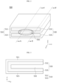
FIG. 1 is a diagram showing a battery cell according to an embodiment of the present disclosure. -
FIG. 2 is a perspective view showing a gas discharge unit ofFIG. 1 . -
FIG. 3 is a cross-sectional view, taken along the cutting line A-A' ofFIG. 2 . -
FIG. 4 is a cross-sectional view, taken along the cutting line B-B' ofFIG. 2 . -
FIG. 5 is a cross-sectional view, taken along the cutting line a-a' ofFIG. 1 . -
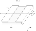
FIG. 6 is a diagram showing a shape of the gas discharge unit ofFIG. 2 before being folded. - Hereinafter, with reference to the accompanying drawings, various embodiments of the present disclosure will be described in detail so as to be easily implemented by those skilled in the art. The present disclosure may be implemented in various different forms and is not limited to the embodiments described herein.
- In order to clearly explain the present disclosure, parts irrelevant to the description are omitted, and identical or similar components are endowed with the same reference signs throughout the specification.
- In addition, since the size and thickness of each component shown in the drawings are arbitrarily expressed for convenience of description, the present disclosure is not necessarily limited to the drawings. In order to clearly express various layers and regions in the drawings, the thicknesses are enlarged. Also, in the drawings, for convenience of explanation, the thickness of some layers and regions is exaggerated.
- In addition, throughout the specification, when a part "includes" a certain component, it means that other components may be further included, rather than excluding other components, unless otherwise stated.
- In addition, throughout the specification, when referring to "top view", it means that the target part is viewed from above, and when referring to "cross-sectional view", it means that a vertically-cut section of the target part is viewed from a side.
-
FIG. 1 is a diagram showing a battery cell according to an embodiment of the present disclosure. - Referring to
FIG. 1 , thebattery cell 100 according to an embodiment of the present disclosure includes abattery case 200 having anaccommodation portion 210 in which anelectrode assembly 110 is mounted, and asealing portion 250 formed by sealing an outer periphery thereof; and agas discharge unit 500 inserted into thesealing portion 250. - The
battery case 200 may be a laminate sheet including a resin layer and a metal layer. More specifically, thebattery case 200 may be made of a laminate sheet, and may include an outer resin layer forming the outermost layer, a barrier metal layer preventing penetration of materials, and an inner resin layer for sealing. - The
electrode assembly 110 may have a structure of a jelly-roll type (winding type), a stack type (lamination type), or a composite type (stack/folding type). More specifically, theelectrode assembly 110 may include a positive electrode, a negative electrode, and a separator disposed therebetween. - The
electrode lead 300 is electrically connected to anelectrode tab 115 included in theelectrode assembly 110, and protrudes out of thebattery case 200 via thesealing portion 250. In addition, thelead film 400 is located at a portion corresponding to thesealing portion 250 in at least one of an upper portion and a lower portion of theelectrode lead 300. Accordingly, thelead film 400 may improve the sealing properties of thesealing portion 250 and the electrode lead 300 while preventing a short circuit from occurring in theelectrode lead 300 during laminating. - The
lead film 400 may have a wider width than theelectrode lead 300. Here, the width of thelead film 400 means a maximum value of the distance between one end and the other end of thelead film 400 in a direction orthogonal to the protruding direction of theelectrode lead 300, and the width of theelectrode lead 300 means a maximum value of the distance between one end and the other end of theelectrode lead 300 in a direction orthogonal to the protruding direction of theelectrode lead 300. Thelead film 400 may have a greater length than the sealingportion 250, but may have a smaller length than theelectrode lead 300. Here, the length of thelead film 400 means a maximum value of the distance between one end and the other end of the lead film in the protruding direction of theelectrode lead 300, and the length of the sealingportion 250 means a maximum value of the distance between one end and the other end of the sealingportion 250 in the protruding direction of theelectrode lead 300. The length of theelectrode lead 300 means a maximum value of the distance between one end and the other end of theelectrode lead 300 in the protruding direction of theelectrode lead 300. Accordingly, thelead film 400 may prevent the side surface of theelectrode lead 300 from being exposed to the outside without interfering with the electrical connection of theelectrode lead 300. - The
gas discharge unit 500 is inserted into the sealingportion 250. Here, thegas discharge unit 500 may be fused together with the sealingportion 250, and thegas discharge unit 500 may be fixed via the sealingportion 250. For example, thegas discharge unit 500 may be heat-fused and/or press-fused together with the sealingportion 250. - More specifically, as shown in
FIG. 1 , thegas discharge unit 500 may be located in the outer periphery of the sealingportion 250 where theelectrode lead 300 is not located. In other words, thegas discharge unit 500 may be inserted into the sealingportion 250 adjacent to a side of theelectrode assembly 110. Accordingly, thegas discharge unit 500 may be manufactured very simply and sufficiently secure a gas discharge path by thegas discharge unit 500 without interfering with the electrical connection of theelectrode lead 300. - As another example, although not specifically shown in the drawings, the
gas discharge unit 500 may be located in the outer periphery of the sealingportion 250 where theelectrode lead 300 is located. In other words, thegas discharge unit 500 may be located in the same outer periphery as theelectrode lead 300, but spaced apart from theelectrode lead 300. Accordingly, since thegas discharge unit 500 protrudes in the same direction as theelectrode lead 300, there is an advantage in that the space efficiency of thebattery cell 100 may be further improved. - Hereinafter, the
gas discharge unit 500 will be described in more detail. -
FIG. 2 is a perspective view showing a gas discharge unit ofFIG. 1 .FIG. 3 is a cross-sectional view, taken along the cutting line A-A' ofFIG. 2 .FIG. 4 is a cross-sectional view, taken along the cutting line B-B' ofFIG. 2 . - Referring to
FIG. 1 , thegas discharge unit 500 protrudes from the inside of thebattery case 200 toward the outside of thebattery case 200. More specifically, thegas discharge unit 500 may protrude from the inside of thebattery case 200 toward the outside of thebattery case 200 via the sealingportion 250. - Referring to
FIGS. 1 to 4 , thegas discharge unit 500 includes anon-adhesive layer 530 and anadhesive layer 510 located on thenon-adhesive layer 530, and thenon-adhesive layer 530 and theadhesive layer 510 are bent to be opened toward the inside of thebattery case 200. Here, thegas discharge unit 500 has a structure in which theadhesive layer 510 surrounds an outer surface of thenon-adhesive layer 530. That is, an inner surface of thegas discharge unit 500 is formed as thenon-adhesive layer 530, and an outer surface of thegas discharge unit 500 may be formed as theadhesive layer 510. - Here, the
adhesive layer 510 may refer to an adhesive layer that can be adhered by heat-fusion and/or press-fusion. In addition, the non-adhesive layer 53 may refer to a non-adhesive layer that cannot be adhered by heat-fusion and/or press-fusion. - Accordingly, the sealing degree between the
gas discharge unit 500 and the sealingportion 250 may be improved due to theadhesive layer 510 located on the outer surface of thegas discharge unit 500. - Referring to
FIGS. 1 to 4 , thenon-adhesive layer 530 includes a firstnon-adhesive layer 531 and a secondnon-adhesive layer 535 spaced apart from each other. Here, an end of the firstnon-adhesive layer 531 and an end of the secondnon-adhesive layer 535 adjacent to the outer side of the sealingportion 250 are connected and integrated with each other. That is, the ends of the firstnon-adhesive layer 531 and the secondnon-adhesive layer 535 opposite to the ends connected to each other are spaced apart from each other, so that one surface of thenon-adhesive layer 530 may be opened toward the inside of thebattery case 200. - Referring to
FIGS. 2 and 3 , thegas discharge unit 500 includes agas inlet 550 located between the firstnon-adhesive layer 531 and the secondnon-adhesive layer 535. Here, thegas inlet 550 is opened toward the inside of thebattery case 200. More specifically, thegas inlet 550 may refer to a space spaced apart between the firstnon-adhesive layer 531 and the secondnon-adhesive layer 535. - Accordingly, in the
battery cell 100 according to this embodiment, since thegas inlet 550 is formed at one surface of thegas discharge unit 500 located inside thebattery case 200, the gas generated inside thebattery cell 100 may be easily introduced into thegas discharge unit 500. - Referring to
FIGS. 1 to 3 , theadhesive layer 510 includes a firstadhesive layer 511 located on the upper surface of the firstnon-adhesive layer 531 and a secondadhesive layer 515 located on the lower surface of the secondnon-adhesive layer 535. Here, an end of the firstadhesive layer 511 and an end of the secondadhesive layer 515 adjacent to the outer side of the sealingportion 250 may be connected and integrated with each other. That is, theadhesive layer 510 extends along the outer surface of thenon-adhesive layer 530, and one surface of theadhesive layer 510 may be opened toward the inside of thebattery case 200. - Referring to
FIG. 2 , based on a protruding direction of thegas discharge unit 500, the firstadhesive layer 511 extends along the side surface of the firstnon-adhesive layer 531, and the secondadhesive layer 515 extends along the side surface of the secondnon-adhesive layer 535. More specifically, the firstadhesive layer 511 extends along both side surfaces of the firstnon-adhesive layer 531, respectively, and the secondadhesive layer 515 extends along both side surfaces of the secondnon-adhesive layer 535, respectively. - Accordingly, in the
gas discharge unit 500, the side surface of thenon-adhesive layer 530 is covered by theadhesive layer 510, so that thenon-adhesive layer 530 is not exposed to the outside. That is, it is possible to prevent moisture in the outside of thebattery cell 100 from penetrating into thebattery cell 100 through thenon-adhesive layer 530. - Referring to
FIGS. 2 and4 , based on the protruding direction of thegas discharge unit 500, the firstadhesive layer 511 and the secondadhesive layer 515 extend between the firstnon-adhesive layer 531 and the secondnon-adhesive layer 535, respectively. In other words, the firstadhesive layer 511 extends at both ends of the lower surface of the firstnon-adhesive layer 531, respectively, and the secondadhesive layer 515 extends at both ends of the upper surface of the secondnon-adhesive layer 535, respectively. - Here, the
adhesive layer 510 is not formed in the center portion of the lower surface of the firstnon-adhesive layer 531 and the upper surface of the secondnon-adhesive layer 535. That is, thegas inlet 550 is formed in the center portion of the lower surface of the firstnon-adhesive layer 531 and the upper surface of the secondnon-adhesive layer 535, and a pair of firstadhesive layers 511 and a pair of secondadhesive layers 515 are be located at both sides of thegas inlet 550, respectively. In this case, in the pair of firstadhesive layers 511 and the pair of secondadhesive layers 515 respectively located at both sides of thegas inlet 550, the pair of firstadhesive layers 511 and the pair of secondadhesive layers 515 may be adhered to each other when being fused with the sealingportion 250. - Accordingly, since the
gas discharge unit 500 includes theadhesive layers 510 formed at both sides of thegas inlet 550, the height of thegas inlet 550 may be relatively increased while increasing the sealing strength of thegas discharge unit 500, so gas may be introduced and discharged easily through thegas inlet 550. - In addition, the
gas discharge unit 500 may adjust the width of thegas inlet 550 by adjusting the length of theadhesive layer 510 formed at both sides of thegas inlet 550. Here, the length of theadhesive layer 510 means a maximum value of the distance between one end and the other end of theadhesive layer 510 in a direction orthogonal to the protruding direction of thegas discharge unit 500. The width of thegas inlet 550 means a maximum value of the distance between one end and the other end of thegas inlet 550 in a direction orthogonal to the protruding direction of thegas discharge unit 500. - Accordingly, when the length of the
adhesive layers 510 formed at both sides of thegas inlet 550 is relatively small, the width of thegas inlet 550 may be relatively large, so that the gas may be introduced and discharged more easily through thegas inlet 550. In addition, when the length of theadhesive layers 510 formed at both sides of thegas inlet 550 is relatively long, the sealing degree of thegas discharge unit 500 may be further improved. - Here, the
non-adhesive layer 530 may a film made of a non-adhesive material. For example, the non-adhesive material may be formed of a fluorine-based polymer material. The fluorine-based polymer material may be at least one of polytetrafluoroethylene (PTFE), polyvinylidene fluoride (PVDF), polymethylpentene (TPX), fluorinated ethylene propylene (FEP), and perfluoroalkoxyalkane (PFA). However, it is not limited thereto, and any material having a relatively high melting point and thus is not dissolved during fusion with the sealingportion 250 may be included in this embodiment. The fluorine-based polymer material is advantageous for moisture sealing and has the property of easily permeating gas. In addition, it is a material that is stable in the environment within thebattery cell 100. For example, it is a material that does not react with the electrolyte contained inbattery cell 100. - In one embodiment of the present disclosure, the gas permeability of the
non-adhesive layer 530 may be 40 Barrer or more at 60°C. For example, the carbon dioxide permeability of thenon-adhesive layer 530 may satisfy the above range. - In one embodiment of the present disclosure, the
non-adhesive layer 530 may be made of a fluorine-based polymer material. The fluorine-based polymer material may be at least one of polytetrafluoroethylene (PTFE), polyvinylidene fluoride (PVDF), polymethylpentene (TPX), fluorinated ethylenepropylene (FEP), and perfluoroalkoxyalkane (PFA), as mentioned above. For example, the fluorine-based polymer material may be at least one of polytetrafluoroethylene (PTFE), polyvinylidene fluoride (PVDF), polymethylpentene (TPX), fluorinated ethylenepropylene (FEP), and perfluoroalkoxyalkane (PFA), which satisfy the gas permeability and/or the moisture penetration amount mentioned above. - Here, the
adhesive layer 510 may be made of an adhesive composition including at least one of a polyolefin-based material, an epoxy, and polyvinyl chloride (PVC). For example, the polyolefin-based material may be polyethylene (PE), polypropylene (PP), or the like. However, the present invention is not limited thereto, and any material that is fused and adhered together with the sealingportion 250 may be included in this embodiment. - The
adhesive layer 510 may have a lower melting point than thenon-adhesive layer 530. Accordingly, the sealing property may be further improved. - In an embodiment of the present disclosure, the gas permeability of the
adhesive layer 510 may be 20 Barrer to 60 Barrer, or 30 Barrer to 40 Barrer at 60°C. For example, the carbon dioxide permeability of theadhesive layer 510 may satisfy the above range. In addition, the gas permeability may satisfy the above range at 60°C based on a thickness of 200 µm of theadhesive layer 510. When the gas permeability of theadhesive layer 510 satisfies the above range, the gas generated inside the secondary battery may be more effectively discharged. - In this specification, the gas permeability may be measured by ASTM F2476-20.
- In one embodiment of the present disclosure, the moisture penetration amount of the
adhesive layer 510 may be 0.02 g to 0.2 g, or 0.02 g to 0.04 g, or 0.06 g or 0.15 g for 10 years at 25°C, 50 %RH. If the moisture penetration amount of theadhesive layer 510 satisfies the above range, it may be more effective to prevent penetration of moisture introduced from theadhesive layer 510. - In one embodiment of the present disclosure, the
adhesive layer 510 may have a gas permeability of 20 Barrer to 60 Barrer at 60°C and a moisture penetration amount of 0.02 g to 0.2 g at 25°C, 50% RH for 10 years. If the gas permeability and the moisture penetration amount of theadhesive layer 510 satisfy the above ranges, it may be more effective to prevent moisture penetration from the outside while discharging the gas generated inside the secondary battery. - The moisture penetration amount of the
adhesive layer 510 may be measured by adopting the ASTM F 1249 method. At this time, the moisture penetration amount may be measured using equipment officially certified by MCOON. - In an embodiment of the present disclosure, the
adhesive layer 510 may be made of an adhesive composition consisting of at least one of a polyolefin-based material, an epoxy, and polyvinyl chloride (PVC), and the polyolefin-based material may be polyethylene (PE), polypropylene (PP) or the like, as mentioned above. For example, theadhesive layer 510 may be polyethylene (PE), polypropylene (PP), or the like, which satisfy the gas permeability and/or the moisture penetration amount mentioned above. - In addition, since the
adhesive layer 510 is made of the above material, it is possible to maintain airtightness of thebattery cell 100 and prevent the internal electrolyte from leaking. - In addition, the
adhesive layer 510 may be a film made of the adhesive composition. Also, theadhesive layer 510 may be formed by applying the adhesive composition on the non-adhesive layer. However, the shape of theadhesive layer 510 is not limited thereto, and any shape capable of easily surrounding the outer surface of thenon-adhesive layer 530 may be used without limitation. - Accordingly, as shown in
FIGS. 2 to 4 , since thegas discharge unit 500 has a structure in which theadhesive layer 510 made of the above material becomes the outer surface of thegas discharge unit 500, theadhesive layer 510 may be fused and adhered together with the sealingportion 250. In addition, thenon-adhesive layer 530 made of the above material is located inside thegas discharge unit 500, and the firstnon-adhesive layer 531 and the secondnon-adhesive layer 535 facing each other are not fused with each other, so the inside of thegas discharge unit 500 serves as a gas discharge passage. Moreover, thenon-adhesive layer 530 of the above material may prevent moisture in the outside of thebattery cell 100 from penetrating into thebattery cell 100 while improving the external discharge of the gas generated inside thebattery cell 100. - In addition, the
gas discharge unit 500 having the above structure is designed to be simply inserted when assembling thebattery cell 100, so it is possible to assemble a battery cell having a new structure while maintaining the existing battery cell manufacturing process. - The thickness of the
adhesive layer 510 may be equal to or smaller than the thickness of thenon-adhesive layer 530. More specifically, theadhesive layer 510 may have a thickness of 0.1 µm or more and 100 µm or less. More specifically, theadhesive layer 510 may have a thickness of 0.5 µm or more and 90 µm or less. For example, theadhesive layer 510 may have a thickness of 1 µm or more and 80 µm or less. In addition, thenon-adhesive layer 530 may have a thickness of 10 µm or more and 500 µm or less. More specifically, thenon-adhesive layer 530 may have a thickness of 15 µm or more and 450 µm or less. For example, thenon-adhesive layer 530 may have a thickness of 20 µm or more and 400 µm or less. - Accordingly, since the
adhesive layer 510 may have a thickness in the above range, it is possible to minimize the effect of thenon-adhesive layer 530 on the gas discharge of thegas discharge unit 500 while maintaining the sealing strength between thegas discharge unit 500 and the sealingportion 250. In addition, since thenon-adhesive layer 530 may have a thickness in the above range, the gas introduced through thegas inlet 550 may be easily discharged through thenon-adhesive layer 530 while suppressing the penetration of moisture flowing into thebattery cell 100. - However, if the thickness of the
adhesive layer 510 is less than 0.1 µm or more than 100 µm, the sealing strength between thegas discharge unit 500 and the sealingportion 250 is too weak, or theadhesive layer 510 prevents the gas discharge of thegas discharge unit 500. In addition, when the thickness of thenon-adhesive layer 530 is less than 10 µm or more than 500 µm, the area of thenon-adhesive layer 530 may be reduced to excessively reduce the discharge amount of gas or to excessively increase the thickness of thegas discharge unit 500. -
FIG. 5 is a cross-sectional view, taken along the cutting line a-a' ofFIG. 1 . - Referring to
FIGS. 2 and5 , in thebattery cell 100 according to an embodiment of the present disclosure, one surface of thegas discharge unit 500 is opened toward the inside of thebattery case 200, and theadhesive layer 510 becomes the outer surface of thegas discharge unit 500, so theadhesive layer 510 and the sealingportion 250 are in contact with each other. In addition, thenon-adhesive layer 530 become the inner surface of thegas discharge unit 500, and agas inlet 550 is formed between the firstnon-adhesive layer 531 and the secondnon-adhesive layer 535. - Accordingly, in this embodiment, in the
gas discharge unit 500, the gas inside thebattery cell 100 may be introduced into thegas inlet 550 formed between thenon-adhesive layer 530. In addition, the gas introduced into thegas inlet 550 may pass through theadhesive layer 510 and thenon-adhesive layer 530 according to the pressure difference with the outside of thebattery case 200, and the gas introduced into thegas inlet 550 may be discharged to the outside. -
FIG. 6 is a diagram showing a shape of the gas discharge unit ofFIG. 2 before being folded. - Referring to
FIGS. 2 and6 , in thebattery cell 100 according to another embodiment of the present disclosure, thegas discharge unit 500 have a structure in which theadhesive layer 510 and thenon-adhesive layer 530 are folded. More specifically, theadhesive layer 510 and thenon-adhesive layer 530 have a structure in which theadhesive layer 510 surrounds the lower surface and both side surfaces of thenon-adhesive layer 530 and surrounds both ends of the upper surface of thenon-adhesive layer 530, respectively. Here, in thegas discharge unit 500, theadhesive layer 510 and thenon-adhesive layer 530 are folded based on the boundary line C-C'. As an example, the boundary line C-C' may correspond to the center line based on the longitudinal direction of theadhesive layer 510 and thenon-adhesive layer 530. - In addition, a region of the upper surface of the
non-adhesive layer 530 where theadhesive layer 510 is not formed may have a rectangular shape as shown inFIG. 6 or may have shapes of various patterns such as a circular shape and an oval shape. - In this method of manufacturing the
gas discharge unit 500, thenon-adhesive layer 530 is disposed approximately in the center of theadhesive layer 510, so that all surfaces except for two surfaces of thenon-adhesive layer 530 are covered with theadhesive layer 510, and both ends of theadhesive layer 510 are folded on thenon-adhesive layer 530 to make a state as shown inFIG. 6 . After that, it is folded based on the boundary line C-C', and theadhesive layers 510 on the folded sides are adhered to each other by as heat-fusion or press-fusion. At this time, a non-adhesive inner space is formed between the foldednon-adhesive layers 530, thereby providing thegas inlet 550. - Accordingly, the
gas discharge unit 500 according to this embodiment may be formed to be folded based on a predetermined boundary line, so the manufacturing process may be relatively easy and the manufacturing cost may also be simplified. - In addition, a battery module according to another embodiment of the present disclosure includes the battery cell described above. Meanwhile, one or more battery modules according to this embodiment may be packaged in a pack case to form a battery pack.
- The battery module described above and the battery pack including the same may be applied to various devices. These devices may be transportation means such as electric bicycles, electric vehicles, hybrid electric vehicles, and the like, but the present disclosure is not limited thereto, and the present disclosure may be applied various devices that can use a battery module and a battery pack including the same, which is also within the scope of the right of the present disclosure.
- The present disclosure has been described in detail. However, it should be understood that the detailed description and specific examples, while indicating preferred embodiments of the disclosure, are given by way of illustration only, since various changes and modifications within the scope of the disclosure as defined by the appended claims will become apparent to those skilled in the art from this detailed description.
Claims (12)
- A battery cell (100), comprising:a battery case (200) having an accommodation portion (210) in which an electrode assembly (110) is mounted, and a sealing portion (250) formed by sealing an outer periphery thereof; anda gas discharge unit (500) inserted into the sealing portion (250),wherein the gas discharge unit (500) protrudes from the inside of the battery case toward the outside of the battery case,wherein the gas discharge unit (500) includes a non-adhesive layer (530) and an adhesive layer (510) located on the non-adhesive layer (530), and the non-adhesive layer (530) and the adhesive layer (510) are bent to be opened toward the inside of the battery case, wherein the non-adhesive layer (530) includes a first non-adhesive layer (531) and a second non-adhesive layer (535) spaced apart from each other, andan end of the first non-adhesive layer (531) and an end of the second non-adhesive layer (535) adjacent to an outer side of the sealing portion (250) are connected and integrated with each other and whereinthe adhesive layer (510) and the non-adhesive layer (530) have a structure in which the adhesive layer (510) surrounds a lower surface and both side surfaces of the non-adhesive layer (530) and surrounds both ends of an upper surface of the non-adhesive layer (530) in continuity with said side surfaces, andthe gas discharge unit (500) has a structure in which the adhesive layer (510) and the non-adhesive layer (530) are folded based on a boundary line perpendicular to said side surfaces providing a non-adhesive inner space formed between the folded non-adhesive layers (530), thereby providing a gas inlet (550) located between the first non-adhesive layer (531) and the second non-adhesive layer (535), and opened toward the inside of the battery case (200).
- The battery cell according to claim 1,wherein the adhesive layer (510) includes a first adhesive layer (511) located on an upper surface of the first non-adhesive layer (531) and a second adhesive layer (515) located on a lower surface of the second non-adhesive layer (535), andan end of the first adhesive layer (511) and an end of the second adhesive layer (515) adjacent to the outer side of the sealing portion are connected and integrated with each other.
- The battery cell according to claim 2,
wherein based on a protruding direction of the gas discharge unit (500), the first adhesive layer (511) extends along a side surface of the first non-adhesive layer (531), and the second adhesive layer (515) extends along a side surface of the second non-adhesive layer (535). - The battery cell according to claim 3,
wherein based on the protruding direction of the gas discharge unit (500), the first adhesive layer (511) and the second adhesive layer (515) extend between the first non-adhesive layer (531) and the second non-adhesive layer (535), respectively. - The battery cell according to claim 4,
wherein a pair of first adhesive layers (511) and a pair of second adhesive layers (515) are located at both sides of the gas inlet, respectively. - The battery cell according to claim 1,
wherein the non-adhesive layer (530) is a film made of a non-adhesive material. - The battery cell according to claim 6,
wherein the non-adhesive material is made of a fluorine-based polymer material. - The battery cell according to claim 6,
wherein the fluorine-based polymer material is at least one of polytetrafluoroethylene (PTFE), polyvinylidene fluoride (PVDF), polymethylpentene (TPX), fluorinated ethylene propylene (FEP), and perfluoroalkoxyalkane (PFA). - The battery cell according to claim 1,
wherein the adhesive layer is made of an adhesive composition consisting of at least one of polyolefin-based material, epoxy, and polyvinyl chloride (PVC). - The battery cell according to claim 9,
wherein the adhesive layer is a film made of the adhesive composition. - The battery cell according to claim 9,
wherein the adhesive layer (510) is formed by applying the adhesive composition on the non-adhesive layer (530). - A battery module, comprising the battery cell according to any one of the preceding claims.
Applications Claiming Priority (2)
| Application Number | Priority Date | Filing Date | Title |
|---|---|---|---|
| KR20210066462 | 2021-05-24 | ||
| PCT/KR2022/007376 WO2022250429A1 (en) | 2021-05-24 | 2022-05-24 | Battery cell and battery module comprising same |
Publications (3)
| Publication Number | Publication Date |
|---|---|
| EP4203161A1 EP4203161A1 (en) | 2023-06-28 |
| EP4203161A4 EP4203161A4 (en) | 2024-07-10 |
| EP4203161B1 true EP4203161B1 (en) | 2025-05-07 |
Family
ID=84229362
Family Applications (1)
| Application Number | Title | Priority Date | Filing Date |
|---|---|---|---|
| EP22811622.4A Active EP4203161B1 (en) | 2021-05-24 | 2022-05-24 | Battery cell and battery module including the same |
Country Status (8)
| Country | Link |
|---|---|
| US (1) | US20230318101A1 (en) |
| EP (1) | EP4203161B1 (en) |
| JP (1) | JP7581492B2 (en) |
| KR (1) | KR20220158642A (en) |
| CN (1) | CN116250131B (en) |
| ES (1) | ES3031813T3 (en) |
| HU (1) | HUE071901T2 (en) |
| WO (1) | WO2022250429A1 (en) |
Families Citing this family (5)
| Publication number | Priority date | Publication date | Assignee | Title |
|---|---|---|---|---|
| CN116250144B (en) * | 2021-04-26 | 2025-12-05 | 株式会社Lg新能源 | Battery cell and battery module including the same |
| CN120266325A (en) * | 2022-12-02 | 2025-07-04 | 株式会社 Lg新能源 | Secondary battery |
| CN116505150A (en) * | 2023-05-16 | 2023-07-28 | 浙江冠宇电池有限公司 | Battery cell and battery |
| JPWO2024248106A1 (en) * | 2023-05-31 | 2024-12-05 | ||
| KR20250001205A (en) * | 2023-06-28 | 2025-01-06 | 주식회사 엘지에너지솔루션 | Pouch cell and manufacturing method of the same |
Family Cites Families (13)
| Publication number | Priority date | Publication date | Assignee | Title |
|---|---|---|---|---|
| JP4622019B2 (en) * | 1999-01-20 | 2011-02-02 | パナソニック株式会社 | Flat battery |
| JP5261882B2 (en) | 2006-03-14 | 2013-08-14 | 大日本印刷株式会社 | Lithium ion battery |
| JP2012190639A (en) * | 2011-03-10 | 2012-10-04 | Sony Corp | Nonaqueous electrolyte battery, battery pack and electronic apparatus |
| JP2016143524A (en) * | 2015-01-30 | 2016-08-08 | ブラザー工業株式会社 | Battery pack |
| KR101904587B1 (en) * | 2015-09-01 | 2018-10-04 | 주식회사 엘지화학 | Battery cell and method for manufacturing the same |
| KR102255525B1 (en) * | 2016-10-07 | 2021-05-25 | 주식회사 엘지에너지솔루션 | Secondary battery and improvement method for cycle life of the secondary battery |
| WO2018110067A1 (en) * | 2016-12-16 | 2018-06-21 | 株式会社村田製作所 | Secondary cell, cell pack, electric vehicle, power storage system, electric tool, and electronic device |
| KR102555751B1 (en) * | 2017-10-17 | 2023-07-14 | 주식회사 엘지에너지솔루션 | Gas Dischargeable Pouch-Type Case for Secondary Battery |
| KR102566979B1 (en) * | 2019-06-04 | 2023-08-16 | 주식회사 엘지에너지솔루션 | secondary battery and battery pack including the same |
| KR102818309B1 (en) * | 2019-10-10 | 2025-06-10 | 주식회사 엘지에너지솔루션 | Gas venting device for secondary battery and secondary battery |
| KR102358975B1 (en) | 2019-11-28 | 2022-02-08 | 선다코리아 주식회사 | Parabolic trough concentrator type solar thermal energy system capable of tracking solar using camera image |
| CN116250144B (en) * | 2021-04-26 | 2025-12-05 | 株式会社Lg新能源 | Battery cell and battery module including the same |
| EP4343801A4 (en) | 2021-05-19 | 2025-02-19 | Dai Nippon Printing Co., Ltd. | WATERPROOF DEGASSING FILM FOR ENERGY STORAGE DEVICE |
-
2022
- 2022-05-24 EP EP22811622.4A patent/EP4203161B1/en active Active
- 2022-05-24 CN CN202280006524.4A patent/CN116250131B/en active Active
- 2022-05-24 KR KR1020220063683A patent/KR20220158642A/en active Pending
- 2022-05-24 HU HUE22811622A patent/HUE071901T2/en unknown
- 2022-05-24 WO PCT/KR2022/007376 patent/WO2022250429A1/en not_active Ceased
- 2022-05-24 ES ES22811622T patent/ES3031813T3/en active Active
- 2022-05-24 JP JP2023515659A patent/JP7581492B2/en active Active
- 2022-05-24 US US18/024,576 patent/US20230318101A1/en active Pending
Also Published As
| Publication number | Publication date |
|---|---|
| US20230318101A1 (en) | 2023-10-05 |
| EP4203161A1 (en) | 2023-06-28 |
| JP7581492B2 (en) | 2024-11-12 |
| EP4203161A4 (en) | 2024-07-10 |
| KR20220158642A (en) | 2022-12-01 |
| CN116250131B (en) | 2026-04-07 |
| WO2022250429A1 (en) | 2022-12-01 |
| ES3031813T3 (en) | 2025-07-11 |
| JP2023542849A (en) | 2023-10-12 |
| HUE071901T2 (en) | 2025-09-28 |
| CN116250131A (en) | 2023-06-09 |
Similar Documents
| Publication | Publication Date | Title |
|---|---|---|
| EP4203161B1 (en) | Battery cell and battery module including the same | |
| US20230170564A1 (en) | Battery Cell, Method for Manufacturing the Same, and Battery Module Including the Same | |
| US12614793B2 (en) | Battery cell and battery cell manufacturing apparatus for manufacturing the same | |
| US12482887B2 (en) | Battery cell and battery module including the same | |
| US12609381B2 (en) | Battery cell with folded multilayer gas discharge unit and battery module including the same | |
| KR102911658B1 (en) | Battery cell and battery module including the same | |
| US12500297B2 (en) | Battery cell and battery module including the same | |
| US20230207987A1 (en) | Battery Cell and Battery Module Including the Same | |
| US12614790B2 (en) | Battery cell and battery module comprising same | |
| KR20240032786A (en) | Battery cell and battery module including the same | |
| EP4243175B1 (en) | Battery cell and battery cell manufacturing apparatus for manufacturing same | |
| US12132215B2 (en) | Battery cell and battery module including the same |
Legal Events
| Date | Code | Title | Description |
|---|---|---|---|
| STAA | Information on the status of an ep patent application or granted ep patent |
Free format text: STATUS: THE INTERNATIONAL PUBLICATION HAS BEEN MADE |
|
| PUAI | Public reference made under article 153(3) epc to a published international application that has entered the european phase |
Free format text: ORIGINAL CODE: 0009012 |
|
| STAA | Information on the status of an ep patent application or granted ep patent |
Free format text: STATUS: REQUEST FOR EXAMINATION WAS MADE |
|
| 17P | Request for examination filed |
Effective date: 20230320 |
|
| AK | Designated contracting states |
Kind code of ref document: A1 Designated state(s): AL AT BE BG CH CY CZ DE DK EE ES FI FR GB GR HR HU IE IS IT LI LT LU LV MC MK MT NL NO PL PT RO RS SE SI SK SM TR |
|
| A4 | Supplementary search report drawn up and despatched |
Effective date: 20240610 |
|
| RIC1 | Information provided on ipc code assigned before grant |
Ipc: H01M 50/178 20210101ALI20240604BHEP Ipc: H01M 50/30 20210101AFI20240604BHEP |
|
| DAV | Request for validation of the european patent (deleted) | ||
| DAX | Request for extension of the european patent (deleted) | ||
| GRAP | Despatch of communication of intention to grant a patent |
Free format text: ORIGINAL CODE: EPIDOSNIGR1 |
|
| STAA | Information on the status of an ep patent application or granted ep patent |
Free format text: STATUS: GRANT OF PATENT IS INTENDED |
|
| INTG | Intention to grant announced |
Effective date: 20241127 |
|
| P01 | Opt-out of the competence of the unified patent court (upc) registered |
Free format text: CASE NUMBER: APP_65665/2024 Effective date: 20241212 |
|
| GRAS | Grant fee paid |
Free format text: ORIGINAL CODE: EPIDOSNIGR3 |
|
| GRAA | (expected) grant |
Free format text: ORIGINAL CODE: 0009210 |
|
| STAA | Information on the status of an ep patent application or granted ep patent |
Free format text: STATUS: THE PATENT HAS BEEN GRANTED |
|
| AK | Designated contracting states |
Kind code of ref document: B1 Designated state(s): AL AT BE BG CH CY CZ DE DK EE ES FI FR GB GR HR HU IE IS IT LI LT LU LV MC MK MT NL NO PL PT RO RS SE SI SK SM TR |
|
| REG | Reference to a national code |
Ref country code: GB Ref legal event code: FG4D |
|
| REG | Reference to a national code |
Ref country code: CH Ref legal event code: EP |
|
| REG | Reference to a national code |
Ref country code: DE Ref legal event code: R096 Ref document number: 602022014447 Country of ref document: DE |
|
| REG | Reference to a national code |
Ref country code: IE Ref legal event code: FG4D |
|
| PGFP | Annual fee paid to national office [announced via postgrant information from national office to epo] |
Ref country code: DE Payment date: 20250520 Year of fee payment: 4 |
|
| PGFP | Annual fee paid to national office [announced via postgrant information from national office to epo] |
Ref country code: ES Payment date: 20250613 Year of fee payment: 4 |
|
| REG | Reference to a national code |
Ref country code: ES Ref legal event code: FG2A Ref document number: 3031813 Country of ref document: ES Kind code of ref document: T3 Effective date: 20250711 |
|
| PGFP | Annual fee paid to national office [announced via postgrant information from national office to epo] |
Ref country code: BE Payment date: 20250520 Year of fee payment: 4 |
|
| PGFP | Annual fee paid to national office [announced via postgrant information from national office to epo] |
Ref country code: FR Payment date: 20250521 Year of fee payment: 4 |
|
| PGFP | Annual fee paid to national office [announced via postgrant information from national office to epo] |
Ref country code: AT Payment date: 20250721 Year of fee payment: 4 |
|
| REG | Reference to a national code |
Ref country code: NL Ref legal event code: MP Effective date: 20250507 |
|
| PGFP | Annual fee paid to national office [announced via postgrant information from national office to epo] |
Ref country code: HU Payment date: 20250827 Year of fee payment: 4 |
|
| REG | Reference to a national code |
Ref country code: HU Ref legal event code: AG4A Ref document number: E071901 Country of ref document: HU |
|
| PG25 | Lapsed in a contracting state [announced via postgrant information from national office to epo] |
Ref country code: PT Free format text: LAPSE BECAUSE OF FAILURE TO SUBMIT A TRANSLATION OF THE DESCRIPTION OR TO PAY THE FEE WITHIN THE PRESCRIBED TIME-LIMIT Effective date: 20250908 Ref country code: FI Free format text: LAPSE BECAUSE OF FAILURE TO SUBMIT A TRANSLATION OF THE DESCRIPTION OR TO PAY THE FEE WITHIN THE PRESCRIBED TIME-LIMIT Effective date: 20250507 |
|
| REG | Reference to a national code |
Ref country code: LT Ref legal event code: MG9D |
|
| PG25 | Lapsed in a contracting state [announced via postgrant information from national office to epo] |
Ref country code: GR Free format text: LAPSE BECAUSE OF FAILURE TO SUBMIT A TRANSLATION OF THE DESCRIPTION OR TO PAY THE FEE WITHIN THE PRESCRIBED TIME-LIMIT Effective date: 20250808 Ref country code: NO Free format text: LAPSE BECAUSE OF FAILURE TO SUBMIT A TRANSLATION OF THE DESCRIPTION OR TO PAY THE FEE WITHIN THE PRESCRIBED TIME-LIMIT Effective date: 20250807 |
|
| PG25 | Lapsed in a contracting state [announced via postgrant information from national office to epo] |
Ref country code: PL Free format text: LAPSE BECAUSE OF FAILURE TO SUBMIT A TRANSLATION OF THE DESCRIPTION OR TO PAY THE FEE WITHIN THE PRESCRIBED TIME-LIMIT Effective date: 20250507 Ref country code: NL Free format text: LAPSE BECAUSE OF FAILURE TO SUBMIT A TRANSLATION OF THE DESCRIPTION OR TO PAY THE FEE WITHIN THE PRESCRIBED TIME-LIMIT Effective date: 20250507 |
|
| REG | Reference to a national code |
Ref country code: AT Ref legal event code: MK05 Ref document number: 1793536 Country of ref document: AT Kind code of ref document: T Effective date: 20250507 |
|
| PG25 | Lapsed in a contracting state [announced via postgrant information from national office to epo] |
Ref country code: BG Free format text: LAPSE BECAUSE OF FAILURE TO SUBMIT A TRANSLATION OF THE DESCRIPTION OR TO PAY THE FEE WITHIN THE PRESCRIBED TIME-LIMIT Effective date: 20250507 |
|
| PG25 | Lapsed in a contracting state [announced via postgrant information from national office to epo] |
Ref country code: HR Free format text: LAPSE BECAUSE OF FAILURE TO SUBMIT A TRANSLATION OF THE DESCRIPTION OR TO PAY THE FEE WITHIN THE PRESCRIBED TIME-LIMIT Effective date: 20250507 Ref country code: AT Free format text: LAPSE BECAUSE OF FAILURE TO SUBMIT A TRANSLATION OF THE DESCRIPTION OR TO PAY THE FEE WITHIN THE PRESCRIBED TIME-LIMIT Effective date: 20250507 |
|
| PG25 | Lapsed in a contracting state [announced via postgrant information from national office to epo] |
Ref country code: RS Free format text: LAPSE BECAUSE OF FAILURE TO SUBMIT A TRANSLATION OF THE DESCRIPTION OR TO PAY THE FEE WITHIN THE PRESCRIBED TIME-LIMIT Effective date: 20250807 |
|
| PG25 | Lapsed in a contracting state [announced via postgrant information from national office to epo] |
Ref country code: IS Free format text: LAPSE BECAUSE OF FAILURE TO SUBMIT A TRANSLATION OF THE DESCRIPTION OR TO PAY THE FEE WITHIN THE PRESCRIBED TIME-LIMIT Effective date: 20250907 |
|
| PG25 | Lapsed in a contracting state [announced via postgrant information from national office to epo] |
Ref country code: LV Free format text: LAPSE BECAUSE OF FAILURE TO SUBMIT A TRANSLATION OF THE DESCRIPTION OR TO PAY THE FEE WITHIN THE PRESCRIBED TIME-LIMIT Effective date: 20250507 |
|
| REG | Reference to a national code |
Ref country code: CH Ref legal event code: H13 Free format text: ST27 STATUS EVENT CODE: U-0-0-H10-H13 (AS PROVIDED BY THE NATIONAL OFFICE) Effective date: 20251223 |
|
| PG25 | Lapsed in a contracting state [announced via postgrant information from national office to epo] |
Ref country code: DK Free format text: LAPSE BECAUSE OF FAILURE TO SUBMIT A TRANSLATION OF THE DESCRIPTION OR TO PAY THE FEE WITHIN THE PRESCRIBED TIME-LIMIT Effective date: 20250507 Ref country code: SM Free format text: LAPSE BECAUSE OF FAILURE TO SUBMIT A TRANSLATION OF THE DESCRIPTION OR TO PAY THE FEE WITHIN THE PRESCRIBED TIME-LIMIT Effective date: 20250507 |
|
| PG25 | Lapsed in a contracting state [announced via postgrant information from national office to epo] |
Ref country code: LU Free format text: LAPSE BECAUSE OF NON-PAYMENT OF DUE FEES Effective date: 20250524 |
|
| PG25 | Lapsed in a contracting state [announced via postgrant information from national office to epo] |
Ref country code: CH Free format text: LAPSE BECAUSE OF NON-PAYMENT OF DUE FEES Effective date: 20250531 |
|
| PG25 | Lapsed in a contracting state [announced via postgrant information from national office to epo] |
Ref country code: CZ Free format text: LAPSE BECAUSE OF FAILURE TO SUBMIT A TRANSLATION OF THE DESCRIPTION OR TO PAY THE FEE WITHIN THE PRESCRIBED TIME-LIMIT Effective date: 20250507 |
|
| PG25 | Lapsed in a contracting state [announced via postgrant information from national office to epo] |
Ref country code: EE Free format text: LAPSE BECAUSE OF FAILURE TO SUBMIT A TRANSLATION OF THE DESCRIPTION OR TO PAY THE FEE WITHIN THE PRESCRIBED TIME-LIMIT Effective date: 20250507 |
|
| PG25 | Lapsed in a contracting state [announced via postgrant information from national office to epo] |
Ref country code: SK Free format text: LAPSE BECAUSE OF FAILURE TO SUBMIT A TRANSLATION OF THE DESCRIPTION OR TO PAY THE FEE WITHIN THE PRESCRIBED TIME-LIMIT Effective date: 20250507 |
|
| PG25 | Lapsed in a contracting state [announced via postgrant information from national office to epo] |
Ref country code: IT Free format text: LAPSE BECAUSE OF FAILURE TO SUBMIT A TRANSLATION OF THE DESCRIPTION OR TO PAY THE FEE WITHIN THE PRESCRIBED TIME-LIMIT Effective date: 20250507 |
|
| REG | Reference to a national code |
Ref country code: DE Ref legal event code: R097 Ref document number: 602022014447 Country of ref document: DE |
|
| PG25 | Lapsed in a contracting state [announced via postgrant information from national office to epo] |
Ref country code: MC Free format text: LAPSE BECAUSE OF FAILURE TO SUBMIT A TRANSLATION OF THE DESCRIPTION OR TO PAY THE FEE WITHIN THE PRESCRIBED TIME-LIMIT Effective date: 20250507 |
|
| PG25 | Lapsed in a contracting state [announced via postgrant information from national office to epo] |
Ref country code: RO Free format text: LAPSE BECAUSE OF FAILURE TO SUBMIT A TRANSLATION OF THE DESCRIPTION OR TO PAY THE FEE WITHIN THE PRESCRIBED TIME-LIMIT Effective date: 20250507 |
|
| PLBE | No opposition filed within time limit |
Free format text: ORIGINAL CODE: 0009261 |
|
| STAA | Information on the status of an ep patent application or granted ep patent |
Free format text: STATUS: NO OPPOSITION FILED WITHIN TIME LIMIT |
|
| REG | Reference to a national code |
Ref country code: CH Ref legal event code: L10 Free format text: ST27 STATUS EVENT CODE: U-0-0-L10-L00 (AS PROVIDED BY THE NATIONAL OFFICE) Effective date: 20260318 |
|
| PGFP | Annual fee paid to national office [announced via postgrant information from national office to epo] |
Ref country code: GB Payment date: 20260324 Year of fee payment: 5 |
|
| PG25 | Lapsed in a contracting state [announced via postgrant information from national office to epo] |
Ref country code: IE Free format text: LAPSE BECAUSE OF NON-PAYMENT OF DUE FEES Effective date: 20250524 |
|
| 26N | No opposition filed |
Effective date: 20260210 |