EP4203151A1 - Apparatus and method for checking for mis-assembly of battery cell activation tray or twisting thereof during operation - Google Patents
Apparatus and method for checking for mis-assembly of battery cell activation tray or twisting thereof during operation Download PDFInfo
- Publication number
- EP4203151A1 EP4203151A1 EP22825405.8A EP22825405A EP4203151A1 EP 4203151 A1 EP4203151 A1 EP 4203151A1 EP 22825405 A EP22825405 A EP 22825405A EP 4203151 A1 EP4203151 A1 EP 4203151A1
- Authority
- EP
- European Patent Office
- Prior art keywords
- tray
- pillar portion
- fence
- check device
- battery cell
- Prior art date
- Legal status (The legal status is an assumption and is not a legal conclusion. Google has not performed a legal analysis and makes no representation as to the accuracy of the status listed.)
- Granted
Links
Images


Classifications
-
- G—PHYSICS
- G01—MEASURING; TESTING
- G01B—MEASURING LENGTH, THICKNESS OR SIMILAR LINEAR DIMENSIONS; MEASURING ANGLES; MEASURING AREAS; MEASURING IRREGULARITIES OF SURFACES OR CONTOURS
- G01B5/00—Measuring arrangements characterised by the use of mechanical techniques
- G01B5/24—Measuring arrangements characterised by the use of mechanical techniques for measuring angles or tapers; for testing the alignment of axes
- G01B5/25—Measuring arrangements characterised by the use of mechanical techniques for measuring angles or tapers; for testing the alignment of axes for testing the alignment of axes
-
- H—ELECTRICITY
- H01—ELECTRIC ELEMENTS
- H01M—PROCESSES OR MEANS, e.g. BATTERIES, FOR THE DIRECT CONVERSION OF CHEMICAL ENERGY INTO ELECTRICAL ENERGY
- H01M50/00—Constructional details or processes of manufacture of the non-active parts of electrochemical cells other than fuel cells, e.g. hybrid cells
- H01M50/20—Mountings; Secondary casings or frames; Racks, modules or packs; Suspension devices; Shock absorbers; Transport or carrying devices; Holders
-
- B—PERFORMING OPERATIONS; TRANSPORTING
- B65—CONVEYING; PACKING; STORING; HANDLING THIN OR FILAMENTARY MATERIAL
- B65D—CONTAINERS FOR STORAGE OR TRANSPORT OF ARTICLES OR MATERIALS, e.g. BAGS, BARRELS, BOTTLES, BOXES, CANS, CARTONS, CRATES, DRUMS, JARS, TANKS, HOPPERS, FORWARDING CONTAINERS; ACCESSORIES, CLOSURES, OR FITTINGS THEREFOR; PACKAGING ELEMENTS; PACKAGES
- B65D25/00—Details of other kinds or types of rigid or semi-rigid containers
- B65D25/02—Internal fittings
- B65D25/10—Devices to locate articles in containers
- B65D25/107—Grooves, ribs, or the like, situated on opposed walls and between which the articles are located
-
- H—ELECTRICITY
- H01—ELECTRIC ELEMENTS
- H01M—PROCESSES OR MEANS, e.g. BATTERIES, FOR THE DIRECT CONVERSION OF CHEMICAL ENERGY INTO ELECTRICAL ENERGY
- H01M10/00—Secondary cells; Manufacture thereof
- H01M10/04—Construction or manufacture in general
-
- H—ELECTRICITY
- H01—ELECTRIC ELEMENTS
- H01M—PROCESSES OR MEANS, e.g. BATTERIES, FOR THE DIRECT CONVERSION OF CHEMICAL ENERGY INTO ELECTRICAL ENERGY
- H01M10/00—Secondary cells; Manufacture thereof
- H01M10/04—Construction or manufacture in general
- H01M10/0404—Machines for assembling batteries
-
- H—ELECTRICITY
- H01—ELECTRIC ELEMENTS
- H01M—PROCESSES OR MEANS, e.g. BATTERIES, FOR THE DIRECT CONVERSION OF CHEMICAL ENERGY INTO ELECTRICAL ENERGY
- H01M10/00—Secondary cells; Manufacture thereof
- H01M10/42—Methods or arrangements for servicing or maintenance of secondary cells or secondary half-cells
- H01M10/4285—Testing apparatus
-
- H—ELECTRICITY
- H01—ELECTRIC ELEMENTS
- H01M—PROCESSES OR MEANS, e.g. BATTERIES, FOR THE DIRECT CONVERSION OF CHEMICAL ENERGY INTO ELECTRICAL ENERGY
- H01M10/00—Secondary cells; Manufacture thereof
- H01M10/42—Methods or arrangements for servicing or maintenance of secondary cells or secondary half-cells
- H01M10/48—Accumulators combined with arrangements for measuring, testing or indicating the condition of cells, e.g. the level or density of the electrolyte
- H01M10/488—Cells or batteries combined with indicating means for external visualization of the condition, e.g. by change of colour or of light density
-
- H—ELECTRICITY
- H01—ELECTRIC ELEMENTS
- H01M—PROCESSES OR MEANS, e.g. BATTERIES, FOR THE DIRECT CONVERSION OF CHEMICAL ENERGY INTO ELECTRICAL ENERGY
- H01M50/00—Constructional details or processes of manufacture of the non-active parts of electrochemical cells other than fuel cells, e.g. hybrid cells
- H01M50/20—Mountings; Secondary casings or frames; Racks, modules or packs; Suspension devices; Shock absorbers; Transport or carrying devices; Holders
- H01M50/204—Racks, modules or packs for multiple batteries or multiple cells
-
- B—PERFORMING OPERATIONS; TRANSPORTING
- B65—CONVEYING; PACKING; STORING; HANDLING THIN OR FILAMENTARY MATERIAL
- B65D—CONTAINERS FOR STORAGE OR TRANSPORT OF ARTICLES OR MATERIALS, e.g. BAGS, BARRELS, BOTTLES, BOXES, CANS, CARTONS, CRATES, DRUMS, JARS, TANKS, HOPPERS, FORWARDING CONTAINERS; ACCESSORIES, CLOSURES, OR FITTINGS THEREFOR; PACKAGING ELEMENTS; PACKAGES
- B65D2585/00—Containers, packaging elements or packages specially adapted for particular articles or materials
- B65D2585/68—Containers, packaging elements or packages specially adapted for particular articles or materials for machines, engines, or vehicles in assembled or dismantled form
- B65D2585/86—Containers, packaging elements or packages specially adapted for particular articles or materials for machines, engines, or vehicles in assembled or dismantled form for electrical components
- B65D2585/88—Batteries
-
- H—ELECTRICITY
- H01—ELECTRIC ELEMENTS
- H01M—PROCESSES OR MEANS, e.g. BATTERIES, FOR THE DIRECT CONVERSION OF CHEMICAL ENERGY INTO ELECTRICAL ENERGY
- H01M10/00—Secondary cells; Manufacture thereof
- H01M10/42—Methods or arrangements for servicing or maintenance of secondary cells or secondary half-cells
- H01M10/44—Methods for charging or discharging
- H01M10/446—Initial charging measures
-
- Y—GENERAL TAGGING OF NEW TECHNOLOGICAL DEVELOPMENTS; GENERAL TAGGING OF CROSS-SECTIONAL TECHNOLOGIES SPANNING OVER SEVERAL SECTIONS OF THE IPC; TECHNICAL SUBJECTS COVERED BY FORMER USPC CROSS-REFERENCE ART COLLECTIONS [XRACs] AND DIGESTS
- Y02—TECHNOLOGIES OR APPLICATIONS FOR MITIGATION OR ADAPTATION AGAINST CLIMATE CHANGE
- Y02E—REDUCTION OF GREENHOUSE GAS [GHG] EMISSIONS, RELATED TO ENERGY GENERATION, TRANSMISSION OR DISTRIBUTION
- Y02E60/00—Enabling technologies; Technologies with a potential or indirect contribution to GHG emissions mitigation
- Y02E60/10—Energy storage using batteries
-
- Y—GENERAL TAGGING OF NEW TECHNOLOGICAL DEVELOPMENTS; GENERAL TAGGING OF CROSS-SECTIONAL TECHNOLOGIES SPANNING OVER SEVERAL SECTIONS OF THE IPC; TECHNICAL SUBJECTS COVERED BY FORMER USPC CROSS-REFERENCE ART COLLECTIONS [XRACs] AND DIGESTS
- Y02—TECHNOLOGIES OR APPLICATIONS FOR MITIGATION OR ADAPTATION AGAINST CLIMATE CHANGE
- Y02P—CLIMATE CHANGE MITIGATION TECHNOLOGIES IN THE PRODUCTION OR PROCESSING OF GOODS
- Y02P70/00—Climate change mitigation technologies in the production process for final industrial or consumer products
- Y02P70/50—Manufacturing or production processes characterised by the final manufactured product
Definitions
- the present invention relates to a check device and a check method for the mal-assembly or the twisting during operation of the battery cell activation tray.
- the secondary batteries depending on the shape of the battery case, they are classified into a cylindrical battery and a prismatic battery in which the electrode assembly is embedded in a cylindrical or prismatic metal can, and a pouch-type battery in which the electrode assembly is embedded in a pouch-type case made of an aluminum laminate sheet.
- the electrode assembly embedded in the battery case is a chargeable power generating element consisting of a stacked structure of positive electrode/separator/negative electrode, and are classified into a jelly-roll type obtained by interposing a separator between the positive and negative electrodes of a long sheet type coated with an active material and the negative electrode and then winding it, and a stack type obtained by sequentially stacking a plurality of positive and negative electrodes of a predetermined size with a separator interposed therebetween.
- a material mixed with an active material, a binder and a plasticizer is applied to a positive electrode current collector and a negative electrode current collector to prepare a positive electrode and a negative electrode, and then these are laminated on both sides of the separator to form a battery cell of a predetermined shape, and then the battery cell is inserted into the battery case and sealed.
- the activation process is always performed before shipment of the product.
- the activation process is a process of activating a battery and removing gas by repeating charging and discharging.
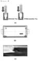
- a process of inserting battery cells into the activation tray as shown in FIG. 1 is performed, and after the activation process is completed, the battery cells are taken out from the activation tray.
- the activation tray is composed of an inner tray 20 on which the battery cell is mounted and an external tray 10 on which the inner tray is fixed.
- the activation tray may be incorrectly assembled when the inner tray 20 and the external tray 10 are assembled, and also, during operation (during the performing of the activation process), the inner tray 20 may be twisted from the external tray 10.
- the inner tray collides with the battery cells, and external dents, scratches, cracks, etc. may occur on the battery cells, as shown in FIGS. 2 and 3 . These damage to the cells may cause the deterioration of the quality of the battery cell and cause the failure of the equipment.
- the present invention has been devised to solve the above problems of the prior art, and it is an object of the present invention to provide a check device that can check the mal-assembly or the twisting during operation of the battery cell activation tray very simply and effectively.
- the present invention provides a check device for checking the occurrence of the mal-assembly or the twisting during operation of the battery cell activation tray, which comprises an external tray equipped with a fence on the outer periphery of the external tray; and an inner tray for accommodating a battery cell fixed at a predetermined distance from the fence on the bottom surface of the external tray, in which a certain separation distance exists between the fence provided in the external tray and the vertical direction structure of the inner tray facing away from the fence, wherein the check device comprises an upper pillar portion and a lower pillar portion extending from the upper pillar portion, the upper pillar portion has a thickness greater than the standard of the separation distance, the lower pillar portion has a thickness smaller than the standard of the separation distance, one surface of the upper pillar portion and the lower pillar portion, which is the basis of the thickness, forms a single plane, and the other surface, which is the basis of the thickness, has a shape in which a step difference corresponding to the thickness difference is formed.
- the present invention provides a check method for mal-assembly or the twisting during operation of the battery cell activation tray using the check device, comprising the steps of,
- the present invention provides a check method for mal-assembly or the twisting during operation of the battery cell activation tray using the check device, comprising the steps of,
- the check device of the present invention If the check device of the present invention is used, the mal-assembly or the twisting during operation of the inner tray of the activation tray can be checked very simply and effectively.
- the mal-assembly or the twisting during operation of the inner tray of the activation tray can be checked very simply and effectively.
- the above check device and check method can effectively solve the problem that the battery cell collides with the inner tray and external dents, scratches, cracks, etc. occur on the battery cell.
- FIG. 1 is a perspective view showing the structure of the battery cell activation tray.
- the activation tray is composed of an inner tray 20 on which the battery cell is mounted and an external tray 10 on which the inner tray is fixed.
- the activation tray may be incorrectly assembled when assembling the inner tray 20 and the external tray 10, and also during operation (during the execution of the activation process), a case in which the inner tray 20 is twisted in the external tray 10 occurs.
- the inner tray and the battery cell may collide, causing external dents, scratches, and cracks in the battery cell, as shown in FIGS. 2 and 3 . These damages to the cell can cause the deterioration of the quality of the battery cell and cause the failure of the equipment.
- One embodiment of the present invention provides a check device and check method for the mal-assembly or the twisting during operation of the battery cell activation tray, which can effectively improve the above problems.
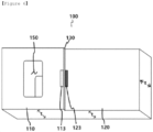
- the check device 100 for the mal-assembly or the twisting during operation of the battery cell activation tray is a check device 100 that checks the occurrence of mal-assembly or the twisting during operation of the battery cell activation tray 30, which comprises an external tray 10 equipped with a fence on the outer periphery of the external tray; and an inner tray 20 for accommodating a battery cell fixed at a predetermined distance from the fence on the bottom surface of the external tray, as shown in FIG. 1 , wherein a certain separation distance exists between the fence 12 provided in the external tray 10 and the vertical direction structures 22 and 24 of the inner tray facing away from the fence.
- the check device 100 comprises an upper pillar portion 110 and a lower pillar portion 120 extending from the upper pillar portion, as shown in FIGS. 4 to 7 , the upper pillar portion 110 has a thickness greater than the standard of the separation distance, the lower pillar portion 120 has a thickness smaller than the standard of the separation distance, one surface of the upper pillar portion 110 and the lower pillar portion 120, which is the basis of the thickness, forms a single plane, and a step 130 corresponding to the thickness difference is formed on the other surface serving as a basis for the thickness.
- the "standard of separation distance” refers to a standard in which the separation distance between the fence 12 provided in the external tray 10 and the vertical direction structures 22 and 24 of the inner tray facing away from the fence is defined in advance as a predetermined length.
- Each of the upper pillar portion 110 and the lower pillar portion 120 may have a uniform thickness, but is not limited thereto, and if the thickness of the portion adjacent to the step 130 satisfies the above-mentioned thickness criterion, a desired effect may be obtained.
- the upper pillar portion and the lower pillar portion extending from the upper pillar portion may have the shape of a polygonal column, a cylinder, an elliptical column, etc., and among them, it can be convenient to use in the case of a polygonal column, and in particular, it can be used more conveniently if it has a shape similar to a rectangular column.
- the upper pillar portion 110 may have a thickness of 100.01% to 110% compared to the standard of the separation distance, and the lower pillar portion 120 may have a thickness of 90% to 99.99% compared to the standard of the separation distance, but is not limited thereto.
- the check device 100 may comprise a form as shown in FIGS. 4 and 5 applied to the side surface of the battery cell activation tray and a form as shown in FIGS. 6 and 7 applied to the rear surface (end surface of the inner tray).
- the check device 100 may be made of various materials such as metal, polymer, wood, etc., and the material thereof is not particularly limited.
- the check device 100 when checking the occurrence of the mal-assembly or the twisting during operation of the battery cell activation tray, as shown in FIGS. 8 and 9 , the check device is inserted into the separation space formed between the fence 12 and the vertical direction structures 22 and 24 of the inner tray from the lower pillar portion in a top-down direction, in a state where the portion forming the single plane is placed in contact with one side 22 in the longitudinal direction of the inner tray. At this time, as shown in FIGS.
- the check device provides a criterion for discrimination as normal, and if the lower pillar portion 120 is caught on the fence 12 or the upper pillar portion 110 is inserted into the space, it provides a criterion for discrimination as abnormal.
- the check device 100 when checking the occurrence of the mal-assembly or the twisting during operation of the battery cell activation tray, as shown in FIGS. 8 and 10 , the check device is inserted from the lower pillar portion 120 to the separation space formed between the fence 12 and the vertical direction structures 22 and 24 of the inner tray from the edge of the inner tray 20 to the center in the end surface of the inner tray, in a state where the portion forming the single plane is placed in contact with the fence 12 adjacent to the edge of the distal end 24 of the inner tray 20.
- the check device provides a criterion for discrimination as normal, and if the lower pillar portion 120 is caught on the vertical direction structures 22 and 24 of the inner tray or the upper pillar portion 110 is inserted into the space, it provides a criterion for discrimination as abnormal.
- the step difference 130 between the upper pillar portion 110 and the lower pillar portion 120 may be formed to have an inclined surface 132, as shown in FIGS. 5 and 7 , and the inclined surface 132 may be formed in a form that gradually reduces the thickness of the upper pillar portion.
- the inclined surface 132 is formed as described above, it is preferable because the degree of mal-assembly or the degree of the twisting during operation of the tray can be easily measured.
- a color marker 113 for identification as normal may be provided, as shown in FIGS. 4 and 6 .
- a color marker 123 for identification as abnormal may be provided at the upper end of the lower pillar portion 120 of the surface where the step difference 130 of the check device is formed.
- a color marker is provided as described above, it is preferable because normal or abnormal can be determined more accurately and conveniently.
- a color marker 113 for identification as normal may be provided, and the inclined surface 132 may be characterized in that a color marker for identification is provided.
- the check method for the mal-assembly or the twisting during operation of the battery cell activation tray is a check method for the mal-assembly or the twisting during operation of the battery cell activation tray using the check device of the present invention, characterized in that it includes,
- the check method for the mal-assembly or the twisting during operation of the battery cell activation tray is a check method for the mal-assembly or the twisting during operation of the battery cell activation tray using the check device of the present invention, characterized in that it comprises,
Landscapes
- Chemical & Material Sciences (AREA)
- Chemical Kinetics & Catalysis (AREA)
- Electrochemistry (AREA)
- General Chemical & Material Sciences (AREA)
- Engineering & Computer Science (AREA)
- Manufacturing & Machinery (AREA)
- Mechanical Engineering (AREA)
- Physics & Mathematics (AREA)
- General Physics & Mathematics (AREA)
- Battery Mounting, Suspending (AREA)
Abstract
Description
- The present application claims the benefit of priority based on
Korean Patent Application No. 10-2021-0077120 filed on June 15, 2021 - The present invention relates to a check device and a check method for the mal-assembly or the twisting during operation of the battery cell activation tray.
- As technology development and demand for mobile devices are increased, the demand for secondary batteries as an energy source is rapidly increasing, and among these secondary batteries, a lot of research has been conducted on a lithium secondary battery with high energy density and discharging voltage, and it is now commercialized and widely used.
- In the case of the secondary batteries, depending on the shape of the battery case, they are classified into a cylindrical battery and a prismatic battery in which the electrode assembly is embedded in a cylindrical or prismatic metal can, and a pouch-type battery in which the electrode assembly is embedded in a pouch-type case made of an aluminum laminate sheet.
- In addition, the electrode assembly embedded in the battery case is a chargeable power generating element consisting of a stacked structure of positive electrode/separator/negative electrode, and are classified into a jelly-roll type obtained by interposing a separator between the positive and negative electrodes of a long sheet type coated with an active material and the negative electrode and then winding it, and a stack type obtained by sequentially stacking a plurality of positive and negative electrodes of a predetermined size with a separator interposed therebetween.
- In general, in manufacturing a lithium secondary battery, first, a material mixed with an active material, a binder and a plasticizer is applied to a positive electrode current collector and a negative electrode current collector to prepare a positive electrode and a negative electrode, and then these are laminated on both sides of the separator to form a battery cell of a predetermined shape, and then the battery cell is inserted into the battery case and sealed. In addition, in order to determine whether the secondary battery is faulty and to secure performance, in particular, stability of lifespan, the activation process is always performed before shipment of the product.
- The activation process is a process of activating a battery and removing gas by repeating charging and discharging. In order to perform the activation process, a process of inserting battery cells into the activation tray as shown in
FIG. 1 is performed, and after the activation process is completed, the battery cells are taken out from the activation tray. - The activation tray is composed of an
inner tray 20 on which the battery cell is mounted and anexternal tray 10 on which the inner tray is fixed. However, the activation tray may be incorrectly assembled when theinner tray 20 and theexternal tray 10 are assembled, and also, during operation (during the performing of the activation process), theinner tray 20 may be twisted from theexternal tray 10. - If the battery cells are inserted in and taken out from the tray incorrectly assembled as above, or from the activation tray whose inner tray is twisted during the activation process, the inner tray collides with the battery cells, and external dents, scratches, cracks, etc. may occur on the battery cells, as shown in
FIGS. 2 and3 . These damage to the cells may cause the deterioration of the quality of the battery cell and cause the failure of the equipment. - Therefore, there is a need for a method that can effectively detect the mal-assembly and the twisting during operation of the activation tray.
-
Korean Laid-open Patent Publication No. 10-2021-0030089 - The present invention has been devised to solve the above problems of the prior art, and it is an object of the present invention to provide a check device that can check the mal-assembly or the twisting during operation of the battery cell activation tray very simply and effectively.
- In addition, it is another object of the present invention to provide a check method that can check the mal-assembly or the twisting during operation of the battery cell activation tray very simply and effectively using the check device described above.
- In order to achieve the above objects, the present invention provides a check device for checking the occurrence of the mal-assembly or the twisting during operation of the battery cell activation tray, which comprises an external tray equipped with a fence on the outer periphery of the external tray; and an inner tray for accommodating a battery cell fixed at a predetermined distance from the fence on the bottom surface of the external tray, in which a certain separation distance exists between the fence provided in the external tray and the vertical direction structure of the inner tray facing away from the fence,
wherein the check device comprises an upper pillar portion and a lower pillar portion extending from the upper pillar portion, the upper pillar portion has a thickness greater than the standard of the separation distance, the lower pillar portion has a thickness smaller than the standard of the separation distance, one surface of the upper pillar portion and the lower pillar portion, which is the basis of the thickness, forms a single plane, and the other surface, which is the basis of the thickness, has a shape in which a step difference corresponding to the thickness difference is formed. - In addition, the present invention
provides a check method for mal-assembly or the twisting during operation of the battery cell activation tray using the check device, comprising the steps of, - (a) preparing a battery cell activation tray, which comprises an external tray equipped with a fence on the outer periphery of the external tray; and an inner tray for accommodating a battery cell fixed at a predetermined distance from a part or all of the fence on the bottom surface of the external tray, wherein a certain separation distance exists between the fence provided in the external tray and the vertical direction structure of the inner tray facing away from the fence,
- (b) inserting the check device into the space formed between the fence and the vertical direction structure of the inner tray from the lower pillar portion in a top-down direction, in a state where the portion in which one surface of each of the upper pillar portion and the lower pillar portion, which is the basis of the thickness, forms a single plane, is placed in contact with the vertical direction structure of the inner tray; and
- (c) determining the case that the lower pillar portion is inserted and the upper pillar portion is caught on the fence, as normal, and the case that the lower pillar portion is caught on the fence or the upper pillar portion is inserted into the space, as abnormal, in the process of inserting the check device.
- In addition, the present invention provides a check method for mal-assembly or the twisting during operation of the battery cell activation tray using the check device, comprising the steps of,
- (a) preparing a battery cell activation tray which comprises an external tray equipped with a fence on the outer periphery of the external tray; and an inner tray for accommodating a battery cell fixed at a predetermined distance from a part or all of the fence on the bottom surface of the external tray, wherein a certain separation distance exists between the fence provided in the external tray and the vertical direction structure of the inner tray facing away from the fence,
- (b) inserting the check device into the separation space formed between the fence and the vertical direction structure of the inner tray from the lower pillar portion in the direction from the edge of the inner tray toward the center of the end surface of the inner tray, in a state where the portion in which one surface of each of the upper pillar portion and the lower pillar portion, which is the basis of the thickness, forms a single plane, is placed in contact with the fence adjacent to the edge of the distal end of the inner tray; and
- (c) determining the case that the lower pillar portion is inserted and the upper pillar portion is caught on the vertical direction structure of the inner tray, as normal, and the case that the lower pillar portion is caught on the vertical direction structure of the inner tray or the upper pillar portion is inserted into the space, as abnormal, in the process of inserting the check device.
- If the check device of the present invention is used, the mal-assembly or the twisting during operation of the inner tray of the activation tray can be checked very simply and effectively.
- In addition, according to the check method of the present invention, the mal-assembly or the twisting during operation of the inner tray of the activation tray can be checked very simply and effectively.
- In addition, when inserting the battery cell into the activation tray or removing it, the above check device and check method can effectively solve the problem that the battery cell collides with the inner tray and external dents, scratches, cracks, etc. occur on the battery cell.
-
-
FIG. 1 is a perspective view showing the structure of the battery cell activation tray. -
FIG. 2 is a view showing a problem that occurs when the battery cell is inserted into the activation tray in which the inner tray is mal-assembled or twisted. -
FIG. 3 is a photograph showing the battery cell mounted on the activation tray and the shape of the battery cell damaged in that process. -
FIGS. 4 to 7 are perspective views illustrating an embodiment of the check device for mal-assembly or the twisting during operation of the battery cell activation tray according to an embodiment of the present invention. -
FIG. 8 is a perspective view showing the state of use of the check device for the mal-assembly or the twisting during operation of the battery cell activation tray according to an embodiment of the present invention. -
FIGS. 9 and10 are cross-sectional views showing the state of use of the check device for the mal-assembly or the twisting during operation of the battery cell activation tray according to an embodiment of the present invention. -
FIG. 11 is a diagram schematically illustrating a criterion for discrimination as normal or abnormal, when using the check device for the mal-assembly or the twisting during operation of the battery cell activation tray according to an embodiment of the present invention. -
FIG. 12 is a photograph of the check device for the mal-assembly or the twisting during operation of the battery cell activation tray according to an embodiment of the present invention. - Hereinafter, embodiments of the present invention will be described in detail with reference to the accompanying drawings so that those skilled in the art to which the present invention pertains can easily practice the present invention. However, the present invention may be embodied in several different forms and is not limited to the embodiments described herein. Throughout the specification, like reference numerals are assigned to like parts.
-
FIG. 1 is a perspective view showing the structure of the battery cell activation tray. As shown inFIG. 1 , the activation tray is composed of aninner tray 20 on which the battery cell is mounted and anexternal tray 10 on which the inner tray is fixed. However, the activation tray may be incorrectly assembled when assembling theinner tray 20 and theexternal tray 10, and also during operation (during the execution of the activation process), a case in which theinner tray 20 is twisted in theexternal tray 10 occurs. - When inserting and taking out battery cells into the activation tray whose inner tray is twisted, on the tray misassembled as above or during the activation process, the inner tray and the battery cell may collide, causing external dents, scratches, and cracks in the battery cell, as shown in
FIGS. 2 and3 . These damages to the cell can cause the deterioration of the quality of the battery cell and cause the failure of the equipment. - One embodiment of the present invention provides a check device and check method for the mal-assembly or the twisting during operation of the battery cell activation tray, which can effectively improve the above problems.
- In an embodiment of the present invention, the
check device 100 for the mal-assembly or the twisting during operation of the battery cell activation tray is acheck device 100 that checks the occurrence of mal-assembly or the twisting during operation of the battery cell activation tray 30, which comprises anexternal tray 10 equipped with a fence on the outer periphery of the external tray; and aninner tray 20 for accommodating a battery cell fixed at a predetermined distance from the fence on the bottom surface of the external tray, as shown inFIG. 1 , wherein a certain separation distance exists between thefence 12 provided in theexternal tray 10 and thevertical direction structures - The
check device 100 comprises anupper pillar portion 110 and alower pillar portion 120 extending from the upper pillar portion, as shown inFIGS. 4 to 7 , theupper pillar portion 110 has a thickness greater than the standard of the separation distance, thelower pillar portion 120 has a thickness smaller than the standard of the separation distance, one surface of theupper pillar portion 110 and thelower pillar portion 120, which is the basis of the thickness, forms a single plane, and astep 130 corresponding to the thickness difference is formed on the other surface serving as a basis for the thickness. - In the above, the "standard of separation distance" refers to a standard in which the separation distance between the
fence 12 provided in theexternal tray 10 and thevertical direction structures - Each of the
upper pillar portion 110 and thelower pillar portion 120 may have a uniform thickness, but is not limited thereto, and if the thickness of the portion adjacent to thestep 130 satisfies the above-mentioned thickness criterion, a desired effect may be obtained. - The upper pillar portion and the lower pillar portion extending from the upper pillar portion may have the shape of a polygonal column, a cylinder, an elliptical column, etc., and among them, it can be convenient to use in the case of a polygonal column, and in particular, it can be used more conveniently if it has a shape similar to a rectangular column.
- The
upper pillar portion 110 may have a thickness of 100.01% to 110% compared to the standard of the separation distance, and thelower pillar portion 120 may have a thickness of 90% to 99.99% compared to the standard of the separation distance, but is not limited thereto. - The
check device 100 may comprise a form as shown inFIGS. 4 and 5 applied to the side surface of the battery cell activation tray and a form as shown inFIGS. 6 and7 applied to the rear surface (end surface of the inner tray). - The
check device 100 may be made of various materials such as metal, polymer, wood, etc., and the material thereof is not particularly limited. - In the case of the
check device 100, when checking the occurrence of the mal-assembly or the twisting during operation of the battery cell activation tray, as shown inFIGS. 8 and9 , the check device is inserted into the separation space formed between thefence 12 and thevertical direction structures side 22 in the longitudinal direction of the inner tray. At this time, as shown inFIGS. 9 and11 , if thelower pillar portion 120 is inserted and theupper pillar portion 110 is caught on thefence 12, the check device provides a criterion for discrimination as normal, and if thelower pillar portion 120 is caught on thefence 12 or theupper pillar portion 110 is inserted into the space, it provides a criterion for discrimination as abnormal. - In the case of the
check device 100, when checking the occurrence of the mal-assembly or the twisting during operation of the battery cell activation tray, as shown inFIGS. 8 and10 , the check device is inserted from thelower pillar portion 120 to the separation space formed between thefence 12 and thevertical direction structures inner tray 20 to the center in the end surface of the inner tray, in a state where the portion forming the single plane is placed in contact with thefence 12 adjacent to the edge of thedistal end 24 of theinner tray 20. At this time, if thelower pillar portion 120 is inserted and theupper pillar portion 110 is caught on thevertical direction structures lower pillar portion 120 is caught on thevertical direction structures upper pillar portion 110 is inserted into the space, it provides a criterion for discrimination as abnormal. - The
step difference 130 between theupper pillar portion 110 and thelower pillar portion 120 may be formed to have aninclined surface 132, as shown inFIGS. 5 and7 , and theinclined surface 132 may be formed in a form that gradually reduces the thickness of the upper pillar portion. - If the
inclined surface 132 is formed as described above, it is preferable because the degree of mal-assembly or the degree of the twisting during operation of the tray can be easily measured. - At the lower end of the
upper pillar portion 110 of the surface on which thestep difference 130 of the check device is formed, acolor marker 113 for identification as normal may be provided, as shown inFIGS. 4 and6 . - In addition, at the upper end of the
lower pillar portion 120 of the surface where thestep difference 130 of the check device is formed, acolor marker 123 for identification as abnormal may be provided. - If a color marker is provided as described above, it is preferable because normal or abnormal can be determined more accurately and conveniently.
- In addition, as shown in
FIGS. 5 and7 , at the lower end of theupper pillar portion 110 of the surface on which thestep difference 130 of the check device is formed, acolor marker 113 for identification as normal may be provided, and theinclined surface 132 may be characterized in that a color marker for identification is provided. - In addition, in an embodiment of the present invention, the check method for the mal-assembly or the twisting during operation of the battery cell activation tray is a check method for the mal-assembly or the twisting during operation of the battery cell activation tray using the check device of the present invention, characterized in that it includes,
- (a) preparing a battery cell activation tray which comprises an external tray equipped with a fence on the outer periphery of the external tray; and an inner tray for accommodating a battery cell fixed at a predetermined distance from a part or all of the fence on the bottom surface of the external tray, wherein a certain separation distance exists between the fence provided in the external tray and the vertical direction structure of the inner tray facing away from the fence;
- (b) inserting the check device into the space formed between the fence and the vertical direction structure of the inner tray from the lower pillar portion in a top-down direction, in a state where the portion in which one surface of each of the upper pillar portion and the lower pillar portion, which is the basis of the thickness, forms a single plane, is placed in contact with the vertical direction structure of the inner tray; and
- (c) determining the case that the lower pillar portion is inserted and the upper pillar portion is caught on the fence, as normal, and the case that the lower pillar portion is caught on the fence or the upper pillar portion is inserted into the space, as abnormal, in the process of inserting the check device.
- In addition, in an embodiment of the present invention, the check method for the mal-assembly or the twisting during operation of the battery cell activation tray is a check method for the mal-assembly or the twisting during operation of the battery cell activation tray using the check device of the present invention, characterized in that it comprises,
- (a) preparing a battery cell activation tray in which a certain separation distance exists between the fence provided in the external tray and the vertical direction structure of the inner tray facing away from the fence, which comprises an external tray equipped with a fence on the outer periphery of the external tray; and an inner tray for accommodating a battery cell fixed at a predetermined distance from a part or all of the fence on the bottom surface of the external tray;
- (b) inserting the check device into the separation space formed between the fence and the vertical direction structure of the inner tray from the lower pillar portion in the direction from the edge of the inner tray toward the center of the end surface of the inner tray, in a state where the portion in which one surface of each of the upper pillar portion and the lower pillar portion, which is the basis of the thickness, forms a single plane, is placed in contact with the fence adjacent to the edge of the distal end of the inner tray; and
- (c) determining the case that the lower pillar portion is inserted and the upper pillar portion is caught on the vertical direction structure of the inner tray, as normal, and the case that the lower pillar portion is caught on the vertical direction structure of the inner tray or the upper pillar portion is inserted into the space, as abnormal, in the process of inserting the check device.
- Although the present invention has been described in connection with the above-mentioned preferred embodiments, various modifications and variations can be made without departing from the spirit and scope of the invention. Accordingly, the appended claims are intended to cover such modifications and variations as fall within the scope of the present invention.
-
- 10: External tray
- 12: External tray fence
- 20: Inner tray
- 22: vertical direction structure and one side in the longitudinal direction of the inner tray
- 24: vertical direction structure and distal end in the longitudinal direction of the inner tray
- 26: Inner tray fixing portion
- 28: Battery cell insertion space
- 29: Battery cell mounting pin
- 100: Check device
- 110: Upper pillar portion
- 113: Color marker for identification as normal
- 120: Lower pillar portion
- 123: Color marker for identification as abnormal
- 130: Step difference portion
- 132: Inclined surface
- 140: Handle
- 150: Handle hole
Claims (9)
- A check device for checking the mal-assembly or the twisting during operation of the battery cell activation tray, which comprises an external tray equipped with a fence on the outer periphery of the external tray; and an inner tray for accommodating a battery cell fixed at a predetermined distance from the fence on the bottom surface of the external tray, in which a certain separation distance exists between the fence provided in the external tray and the vertical direction structure of the inner tray facing away from the fence,
wherein the check device comprises an upper pillar portion and a lower pillar portion extending from the upper pillar portion, the upper pillar portion has a thickness greater than the standard of the separation distance, the lower pillar portion has a thickness smaller than the standard of the separation distance, one surface of the upper pillar portion and the lower pillar portion, which is the basis of the thickness, forms a single plane, and the other surface, which is the basis of the thickness, has a shape in which a step difference corresponding to the thickness difference is formed. - The check device for checking the mal-assembly or the twisting during operation of the battery cell activation tray according to claim 1, wherein when the check device checks the occurrence of the mal-assembly or the twisting during operation of the battery cell activation tray, the check device is inserted into the separation space formed between the fence and the vertical direction structure of the inner tray from the lower pillar portion in a top-down direction, in a state where the portion forming the single plane is placed in contact with one side in the longitudinal direction of the inner tray, and at this time, if the lower pillar portion is inserted and the upper pillar portion is caught on the fence, the check device provides a criterion for discrimination as normal, and if the lower pillar portion is caught on the fence or the upper pillar portion is inserted into the space, it provides a criterion for discrimination as abnormal.
- The check device for checking the mal-assembly or the twisting during operation of the battery cell activation tray according to claim 1, wherein when the check device checks the occurrence of the mal-assembly or the twisting during operation of the battery cell activation tray, the check device is inserted from the lower pillar portion into the separation space formed between the fence and the vertical direction structure of the inner tray from the edge of the inner tray to the center in the end surface of the inner tray, in a state where the portion forming the single plane is placed in contact with the fence adjacent to the edge of the distal end of the inner tray, and at this time, if the lower pillar portion is inserted and the upper pillar portion is caught on the vertical direction structure of the inner tray, the check device provides a criterion for discrimination as normal, and if the lower pillar portion is caught on the vertical direction structure of the inner tray or the upper pillar portion is inserted into the space, it provides a criterion for discrimination as abnormal.
- The check device for checking the mal-assembly or the twisting during operation of the battery cell activation tray according to claim 1, wherein the step difference between the upper pillar portion and the lower pillar portion is formed to have an inclined surface, and the inclined surface is formed in a form that gradually reduces the thickness of the upper pillar portion.
- The check device for checking the mal-assembly or the twisting during operation of the battery cell activation tray according to claim 1, wherein the lower end of the upper pillar portion of the surface, where the step difference of the check device is formed, is provided with a color marker for confirmation as normal.
- The check device for checking the mal-assembly or the twisting during operation of the battery cell activation tray according to claim 5, wherein the upper end of the lower pillar portion of the surface, where the step difference of the check device is formed, is provided with a color marker for confirmation as abnormal.
- The check device for checking the mal-assembly or the twisting during operation of the battery cell activation tray according to claim 4, wherein the lower end of the upper pillar portion of the surface, where the step difference of the check device is formed, is provided with a color mark for confirmation as normal is provided, and the inclined surface is provided with a color marker for identification.
- A check method for the mal-assembly or the twisting during operation of the battery cell activation tray using the check device of claim 1, which comprises,(a) preparing a battery cell activation tray which comprises an external tray equipped with a fence on the outer periphery of the external tray; and an inner tray for accommodating a battery cell fixed at a predetermined distance from a part or all of the fence on the bottom surface of the external tray, wherein a certain separation distance exists between the fence provided in the external tray and the vertical direction structure of the inner tray facing away from the fence;(b) inserting the check device into the space formed between the fence and the vertical direction structure of the inner tray from the lower pillar portion from top to bottom, in a state where the portion in which one surface of each of the upper pillar portion and the lower pillar portion, which is the basis of the thickness, forms a single plane, is placed in contact with the vertical direction structure of the inner tray; and(c) determining the case that the lower pillar portion is inserted and the upper pillar portion is caught on the fence, as normal, and the case that the lower pillar portion is caught on the fence or the upper pillar portion is inserted into the space, as abnormal, in the process of inserting the check device.
- A check method for the mal-assembly or the twisting during operation of the battery cell activation tray using the check device of claim 1, which comprises,(a) preparing a battery cell activation tray which comprises an external tray equipped with a fence on the outer periphery of the external tray; and an inner tray for accommodating a battery cell fixed at a predetermined distance from a part or all of the fence on the bottom surface of the external tray, wherein a certain separation distance exists between the fence provided in the external tray and the vertical direction structure of the inner tray facing away from the fence;(b) inserting the check device into the separation space formed between the fence and the vertical direction structure of the inner tray from the lower pillar portion in the direction from the edge of the inner tray toward the center of the end surface of the inner tray, in a state where the portion in which one surface of each of the upper pillar portion and the lower pillar portion, which is the basis of the thickness, forms a single plane, is placed in contact with the fence adjacent to the edge of the distal end of the inner tray; and(c) determining the case that the lower pillar portion is inserted and the upper pillar portion is caught on the vertical direction structure of the inner tray, as normal, and the case that the lower pillar portion is caught on the vertical direction structure of the inner tray or the upper pillar portion is inserted into the space, as abnormal, in the process of inserting the check device.
Applications Claiming Priority (2)
| Application Number | Priority Date | Filing Date | Title |
|---|---|---|---|
| KR1020210077120A KR20220167873A (en) | 2021-06-15 | 2021-06-15 | Confirmation device for detecting an incorrect assembly or twisting during operation of a battery cell activation tray and Confirmation method of the same |
| PCT/KR2022/095106 WO2022265482A1 (en) | 2021-06-15 | 2022-06-14 | Apparatus and method for checking for mis-assembly of battery cell activation tray or twisting thereof during operation |
Publications (3)
| Publication Number | Publication Date |
|---|---|
| EP4203151A1 true EP4203151A1 (en) | 2023-06-28 |
| EP4203151A4 EP4203151A4 (en) | 2024-08-07 |
| EP4203151B1 EP4203151B1 (en) | 2026-02-18 |
Family
ID=84527578
Family Applications (1)
| Application Number | Title | Priority Date | Filing Date |
|---|---|---|---|
| EP22825405.8A Active EP4203151B1 (en) | 2021-06-15 | 2022-06-14 | Apparatus and method for checking for mis-assembly of battery cell activation tray or twisting thereof during operation |
Country Status (5)
| Country | Link |
|---|---|
| US (1) | US12595997B2 (en) |
| EP (1) | EP4203151B1 (en) |
| KR (1) | KR20220167873A (en) |
| CN (1) | CN116323414B (en) |
| WO (1) | WO2022265482A1 (en) |
Families Citing this family (3)
| Publication number | Priority date | Publication date | Assignee | Title |
|---|---|---|---|---|
| KR20220167873A (en) * | 2021-06-15 | 2022-12-22 | 주식회사 엘지에너지솔루션 | Confirmation device for detecting an incorrect assembly or twisting during operation of a battery cell activation tray and Confirmation method of the same |
| KR20250046971A (en) * | 2023-09-27 | 2025-04-03 | 주식회사 엘지에너지솔루션 | Battery cell tray |
| CN120767518B (en) * | 2025-08-19 | 2025-11-11 | 深圳市超达成智能科技有限公司 | Flexible package battery restraint tray and formation equipment |
Family Cites Families (17)
| Publication number | Priority date | Publication date | Assignee | Title |
|---|---|---|---|---|
| US2021273A (en) * | 1934-07-27 | 1935-11-19 | Vallinos Nicholas | Cigarette package case and opener |
| US5914609A (en) * | 1996-11-08 | 1999-06-22 | Bitrode Corporation | Method and system for battery charging and testing with semi-automatic calibration |
| KR101076412B1 (en) * | 2009-07-07 | 2011-10-25 | (주)이티에이치 | Battery formation jig |
| US8519715B2 (en) * | 2010-11-29 | 2013-08-27 | Volkswagen Ag | Method and system for assembling a battery module |
| KR101067036B1 (en) | 2011-06-13 | 2011-09-22 | 주식회사 금성산업 | Vehicle battery case inspection device |
| KR101875535B1 (en) | 2013-10-16 | 2018-07-06 | 주식회사 엘지화학 | Size checking apparatus for battery case |
| KR101739853B1 (en) * | 2014-09-16 | 2017-05-25 | 에스케이이노베이션 주식회사 | Apparatus for impregnating electrolyte and fabricating method of secondary battery using thereof |
| JP2017020863A (en) | 2015-07-09 | 2017-01-26 | 株式会社豊田自動織機 | Case inspection method |
| KR101771014B1 (en) | 2015-12-22 | 2017-08-24 | 한화첨단소재 주식회사 | Apparatus and method for electric car battery cover air leak detection and the detection result output unit |
| KR101964713B1 (en) * | 2016-12-15 | 2019-04-02 | 주식회사 엘지화학 | Battery Cell Formation Tray Comprising Fixing Member |
| KR102180946B1 (en) * | 2016-12-27 | 2020-11-19 | 주식회사 엘지화학 | Buffer Plate for Uniform SEI Formation, and Battery Manufacturing Method thereof |
| CN110444702A (en) * | 2018-05-02 | 2019-11-12 | 天津尚能巨源能源科技有限公司 | Storage device is used in a kind of production of lithium ion battery |
| JP6644230B1 (en) * | 2019-01-25 | 2020-02-12 | 株式会社ソフトエナジーコントロールズ | Charge / discharge tester |
| KR102724647B1 (en) | 2019-09-09 | 2024-10-30 | 주식회사 엘지에너지솔루션 | Inspection method and apparatus of secondary battery cell in activation process |
| KR20210077120A (en) | 2019-12-17 | 2021-06-25 | 박민철 | management system for supporting sports game progress |
| CN213229479U (en) * | 2020-09-09 | 2021-05-18 | 昆山聚创新能源科技有限公司 | Battery tray |
| KR20220167873A (en) * | 2021-06-15 | 2022-12-22 | 주식회사 엘지에너지솔루션 | Confirmation device for detecting an incorrect assembly or twisting during operation of a battery cell activation tray and Confirmation method of the same |
-
2021
- 2021-06-15 KR KR1020210077120A patent/KR20220167873A/en active Pending
-
2022
- 2022-06-14 EP EP22825405.8A patent/EP4203151B1/en active Active
- 2022-06-14 US US18/032,637 patent/US12595997B2/en active Active
- 2022-06-14 CN CN202280006655.2A patent/CN116323414B/en active Active
- 2022-06-14 WO PCT/KR2022/095106 patent/WO2022265482A1/en not_active Ceased
Also Published As
| Publication number | Publication date |
|---|---|
| US12595997B2 (en) | 2026-04-07 |
| US20230408241A1 (en) | 2023-12-21 |
| EP4203151A4 (en) | 2024-08-07 |
| KR20220167873A (en) | 2022-12-22 |
| WO2022265482A1 (en) | 2022-12-22 |
| EP4203151B1 (en) | 2026-02-18 |
| CN116323414A (en) | 2023-06-23 |
| CN116323414B (en) | 2024-05-14 |
Similar Documents
| Publication | Publication Date | Title |
|---|---|---|
| EP4203151A1 (en) | Apparatus and method for checking for mis-assembly of battery cell activation tray or twisting thereof during operation | |
| US12512534B2 (en) | Crack-prevention sealing block for pouch-shaped secondary batteries, pouch-shaped battery case manufactured using the same, and method of sealing pouch-shaped battery case | |
| US20100028770A1 (en) | Electrode Assembly Having Electrode Tabs of the Same Size in Joint Portion Thereof and Electrochemical Cell Containing the Same | |
| US12358069B2 (en) | Welding apparatus, welding method using the same, and electrode assembly manufactured by the welding method | |
| KR101736548B1 (en) | Method for welding plural electrode tab and electrode lead of secondary battery and secondary battery using the same, method for inspecting poor welding of secondary battery | |
| KR102361705B1 (en) | Rechargeable battery having cover | |
| US20090305134A1 (en) | Electrode Assembly Having Stable Lead-Tap Joint and Electrochemical Cell Containing Them | |
| US20190207265A1 (en) | Battery Cell Having Structure For Prevention of Swelling | |
| EP3168918B1 (en) | Electrode assembly wound in both directions, and lithium secondary battery comprising same | |
| EP2942832A1 (en) | Electrode assembly and battery cell comprising same | |
| KR101791674B1 (en) | Electrode Assembly Comprising Bi-cell and Full-Cell and Secondary Battery Having the Same | |
| KR20130115594A (en) | Rechargeable battery | |
| KR20120028078A (en) | Rechargeable battery | |
| KR20200053784A (en) | System and method for discriminating defective folded electrode tabs of battery cell | |
| KR20160092872A (en) | Electrode assembly and rechargeable battery having electrode ta1p | |
| KR101653320B1 (en) | Jelly-Roll Type Electrode Assembly of Low Resistance And Secondary Battery Comprising the Same | |
| KR20160026259A (en) | Method for Manufacturing Secondary Battery | |
| KR102239364B1 (en) | Lithium secondary battery including cylindrical-jelly roll | |
| EP4199209A1 (en) | Method for detecting misassembly or misalignment during operation of inner tray, and battery cell activation tray | |
| US20260038995A1 (en) | Battery, and Battery Pack and Vehicle Including the Same | |
| US7687196B2 (en) | Prismatic battery and method for manufacturing the same | |
| EP3582293A1 (en) | Battery cell and method for manufacturing electrode lead | |
| KR20150122340A (en) | Jelly-Roll Type Electrode Assembly Having Multi Electrode Tabs | |
| KR20160092871A (en) | Electrode assembly and rechargeable battery having electrode tap | |
| KR20230085489A (en) | Cylindrical battery and method for disassembling the same |
Legal Events
| Date | Code | Title | Description |
|---|---|---|---|
| STAA | Information on the status of an ep patent application or granted ep patent |
Free format text: STATUS: THE INTERNATIONAL PUBLICATION HAS BEEN MADE |
|
| PUAI | Public reference made under article 153(3) epc to a published international application that has entered the european phase |
Free format text: ORIGINAL CODE: 0009012 |
|
| STAA | Information on the status of an ep patent application or granted ep patent |
Free format text: STATUS: REQUEST FOR EXAMINATION WAS MADE |
|
| 17P | Request for examination filed |
Effective date: 20230320 |
|
| AK | Designated contracting states |
Kind code of ref document: A1 Designated state(s): AL AT BE BG CH CY CZ DE DK EE ES FI FR GB GR HR HU IE IS IT LI LT LU LV MC MK MT NL NO PL PT RO RS SE SI SK SM TR |
|
| A4 | Supplementary search report drawn up and despatched |
Effective date: 20240705 |
|
| RIC1 | Information provided on ipc code assigned before grant |
Ipc: H01M 50/204 20210101ALI20240702BHEP Ipc: H01M 10/44 20060101ALI20240702BHEP Ipc: H01M 10/48 20060101ALI20240702BHEP Ipc: H01M 10/42 20060101ALI20240702BHEP Ipc: H01M 10/04 20060101ALI20240702BHEP Ipc: B65D 25/10 20060101ALI20240702BHEP Ipc: H01M 50/20 20210101AFI20240702BHEP |
|
| DAV | Request for validation of the european patent (deleted) | ||
| DAX | Request for extension of the european patent (deleted) | ||
| GRAP | Despatch of communication of intention to grant a patent |
Free format text: ORIGINAL CODE: EPIDOSNIGR1 |
|
| STAA | Information on the status of an ep patent application or granted ep patent |
Free format text: STATUS: GRANT OF PATENT IS INTENDED |
|
| INTG | Intention to grant announced |
Effective date: 20250924 |
|
| P01 | Opt-out of the competence of the unified patent court (upc) registered |
Free format text: CASE NUMBER: UPC_APP_0012729_4203151/2025 Effective date: 20251110 |
|
| GRAS | Grant fee paid |
Free format text: ORIGINAL CODE: EPIDOSNIGR3 |
|
| GRAA | (expected) grant |
Free format text: ORIGINAL CODE: 0009210 |
|
| STAA | Information on the status of an ep patent application or granted ep patent |
Free format text: STATUS: THE PATENT HAS BEEN GRANTED |
|
| AK | Designated contracting states |
Kind code of ref document: B1 Designated state(s): AL AT BE BG CH CY CZ DE DK EE ES FI FR GB GR HR HU IE IS IT LI LT LU LV MC MK MT NL NO PL PT RO RS SE SI SK SM TR |
|
| REG | Reference to a national code |
Ref country code: CH Ref legal event code: F10 Free format text: ST27 STATUS EVENT CODE: U-0-0-F10-F00 (AS PROVIDED BY THE NATIONAL OFFICE) Effective date: 20260218 Ref country code: GB Ref legal event code: FG4D |
|
| REG | Reference to a national code |
Ref country code: IE Ref legal event code: FG4D |
|
| REG | Reference to a national code |
Ref country code: DE Ref legal event code: R096 Ref document number: 602022030789 Country of ref document: DE |