EP4202778A1 - Optical 4f system performing extended convolution operation and operating method thereof - Google Patents
Optical 4f system performing extended convolution operation and operating method thereof Download PDFInfo
- Publication number
- EP4202778A1 EP4202778A1 EP22215986.5A EP22215986A EP4202778A1 EP 4202778 A1 EP4202778 A1 EP 4202778A1 EP 22215986 A EP22215986 A EP 22215986A EP 4202778 A1 EP4202778 A1 EP 4202778A1
- Authority
- EP
- European Patent Office
- Prior art keywords
- data
- result
- fourier transform
- optical
- equation
- Prior art date
- Legal status (The legal status is an assumption and is not a legal conclusion. Google has not performed a legal analysis and makes no representation as to the accuracy of the status listed.)
- Pending
Links
Images



Classifications
-
- G—PHYSICS
- G06—COMPUTING OR CALCULATING; COUNTING
- G06N—COMPUTING ARRANGEMENTS BASED ON SPECIFIC COMPUTATIONAL MODELS
- G06N3/00—Computing arrangements based on biological models
- G06N3/02—Neural networks
- G06N3/04—Architecture, e.g. interconnection topology
- G06N3/0464—Convolutional networks [CNN, ConvNet]
-
- G—PHYSICS
- G06—COMPUTING OR CALCULATING; COUNTING
- G06V—IMAGE OR VIDEO RECOGNITION OR UNDERSTANDING
- G06V10/00—Arrangements for image or video recognition or understanding
- G06V10/88—Image or video recognition using optical means, e.g. reference filters, holographic masks, frequency domain filters or spatial domain filters
- G06V10/89—Image or video recognition using optical means, e.g. reference filters, holographic masks, frequency domain filters or spatial domain filters using frequency domain filters, e.g. Fourier masks implemented on spatial light modulators
- G06V10/893—Image or video recognition using optical means, e.g. reference filters, holographic masks, frequency domain filters or spatial domain filters using frequency domain filters, e.g. Fourier masks implemented on spatial light modulators characterised by the kind of filter
-
- G—PHYSICS
- G02—OPTICS
- G02B—OPTICAL ELEMENTS, SYSTEMS OR APPARATUS
- G02B27/00—Optical systems or apparatus not provided for by any of the groups G02B1/00 - G02B26/00, G02B30/00
- G02B27/42—Diffraction optics, i.e. systems including a diffractive element being designed for providing a diffractive effect
- G02B27/46—Systems using spatial filters
-
- G—PHYSICS
- G06—COMPUTING OR CALCULATING; COUNTING
- G06N—COMPUTING ARRANGEMENTS BASED ON SPECIFIC COMPUTATIONAL MODELS
- G06N20/00—Machine learning
-
- G—PHYSICS
- G06—COMPUTING OR CALCULATING; COUNTING
- G06N—COMPUTING ARRANGEMENTS BASED ON SPECIFIC COMPUTATIONAL MODELS
- G06N3/00—Computing arrangements based on biological models
- G06N3/02—Neural networks
- G06N3/06—Physical realisation, i.e. hardware implementation of neural networks, neurons or parts of neurons
- G06N3/067—Physical realisation, i.e. hardware implementation of neural networks, neurons or parts of neurons using optical means
-
- G—PHYSICS
- G06—COMPUTING OR CALCULATING; COUNTING
- G06N—COMPUTING ARRANGEMENTS BASED ON SPECIFIC COMPUTATIONAL MODELS
- G06N3/00—Computing arrangements based on biological models
- G06N3/02—Neural networks
- G06N3/04—Architecture, e.g. interconnection topology
- G06N3/048—Activation functions
Definitions
- Embodiments of the present disclosure described herein relate to a convolution operation, and more particularly, relate to an optical 4f system performing extended convolution operations and an operating method thereof.
- a convolutional neural network is a type of deep neural network that includes one or more convolution layers.
- the CNN provides good performance in image recognition, video recognition, image classification, medical image analysis, natural language processing, and time-series analysis, and fields to which the CNN is applied continue to expand.
- An optical 4f system refers a system that has a structure in which two lenses are paired and transfers an image from a first lens of one side to a second lens of an opposite side; when the first and second lenses have the same focal length of "f", a distance from an object plane (or an input plane) to the first lens is "f", a distance from the first lens to the second lens is 2f, and a distance from the second lens to an image plane (or an output plane) is "f”. That is, a total length from the object plane to the image plane is 4f.
- Embodiments of the present disclosure provide a method for extending a convolution operation of an optical 4f system such that a convolution operation is performed on an input including a negative number in the optical 4f system, an optical 4f system performing the extended convolution operation, and an operating method of the optical 4f system.
- an optical system includes a first lens that receives input data from an object, a kernel that performs a first Fourier transform on the input data and generates learning data by performing calculation on a result of the first Fourier transform and pattern data, and a second lens that generates result data by performing a second Fourier transform on the learning data, and the input data, the learning data, and the result data include both a positive number and a negative number.
- an operating method of an optical system which includes a first lens, a kernel, and a second lens includes receiving input data from an object through the first lens, performing a first Fourier transform on the input data through the kernel, generating learning data by performing calculation on a result of the first Fourier transform and pattern data, and generating result data by performing a second Fourier transform on the learning data, and the input data, the learning data, and the result data include both a positive number and a negative number.
- the software may be a machine code, firmware, an embedded code, and application software.
- the hardware may include an electrical circuit, an electronic circuit, a processor, a computer, an integrated circuit, integrated circuit cores, a pressure sensor, an inertial sensor, a microelectromechanical system (MEMS), a passive element, or a combination thereof.
- MEMS microelectromechanical system
- FIG. 1 is a diagram illustrating an example of an optical 4f system 100 according to an embodiment of the present disclosure.
- the optical 4f system 100 may include a first lens 110, a kernel 120, and a second lens 130. Assuming that a focal length of each of the first lens 110 and the second lens 130 is "f', a distance between an object 10 and the first lens 110, a distance between the first lens 110 and the second lens 130, and a distance between the second lens 130 and an image 20 are "f", 2f, and "f"; in this case, a total of length may be 4f.
- the first lens 110 may receive input data f ( x,y ) from the object 10 and may perform a first Fourier transform at a location of the kernel 120, and the second lens 130 may perform a second Fourier transform.
- the kernel 120 may serve as a filter between the first Fourier transform and the second Fourier transform and may include pattern data G ( u,v ) associated with learning.
- the convolution operation of the optical 4f system 100 may be implemented by performing the Fourier transform continuously two times. That is, the optical 4f system 100 may output the image 20 corresponding to a result of the convolution operation of the kernel 120 with the object 10 through the lenses 110 and 130.
- the Fourier transform is performed two times, the object 10 and the image 20 are inverted (or reverse) images.
- f ( x,y ) may correspond to the first input image or an input value of a previous CNN layer
- G(u, v) may correspond to an image pattern trained in the CNN
- F ⁇ 1 F f x y u v • G u v x y may correspond to a value (i.e., the output image 20) generated by the optical 4f system 100
- F f x y u v may indicate the first Fourier transform while passing through the first lens 110, which corresponds to the transformation from the x-y plane to the u-v plane.
- F f x y u v • G u v may correspond to an image pattern learning result in the form of multiplying the result of the first Fourier transform and a learning image pattern G ( u, v ) together.
- F ⁇ 1 F f x y u v • G u v x y may indicate the second Fourier transform performed while F f x y u v • G u v obtained by multiplying the result of the first Fourier transform and G ( u , v ) together passes through the second lens 130 and may be expressed in the form of inverse Fourier transform for the convenience of equation expansion in the specification.
- FIG. 2 is a diagram illustrating a result of expressing values associated with an operation performed in the optical 4f system 100 of FIG. 1 through a light amplitude and a light intensity.
- All f ( x,y ) , G ( u , v ), and F ⁇ 1 F f x y u v • G u v x y that are used in the convolution operation using optical 4f system 100 described above are equations based on the light amplitude, and an actual input value and actual output values of the optical 4f system 100 are proportional to the light intensity.
- the actual input value and the actual output values may be expressed in form of
- FIG. 3 illsutrates operation rules FT1 and FT2 of Fourier transform and operation rules IFT1 and IFT2 of inverse Fourier transform, which are used to extend a convolution operation.
- an operator "•” represents a multiplication operation
- an operator " ⁇ ” represents a convolution operation.
- Operation rules of the Fourier transform include the homogeneity FT1 indicating that an output magnitude is proportional to an input magnitude, the additivity FT2 indicating that a total result when plural input signals are added is equal to a result of adding results of individual input signals, and the Fourier transform FT3 for convolution indicating that the convolution operation in the x-y plane is expressed by a multiplication operation in the u-v plane.
- Operation rules of the inverse Fourier transform include the inverse property IFT1 indicating that an original input value is obtained by performing the inverse Fourier transform on a result of the Fourier transform and the distributive property for addition IFT2.
- FIG. 4 illustrates theorems used for extension of a convolution operation.
- f ( x,y ) in the x-y plane a first theorem indicates that an input signal is expressed by a difference between signals f 1 ( x,y ) ⁇ 0 and f 2 ( x , y ) ⁇ 0 being two arbitrary different positive numbers;
- G ( u , v ) in the u-v plane a second theorem indicates that an input signal is expressed by a difference between signals G 1 ( u, v ) ⁇ 0 and G 2 ( u, v ) ⁇ 0 being two arbitrary different positive numbers.
- Equation 1 when the inverse property IFT1 of FIG. 3 is applied, Equation 1 above may be expressed like Equation 2 below through the inverse Fourier transform.
- F ⁇ 1 ⁇ F f x y u v • G ( u, v ) ⁇ ( x , y ) may be calculated through the optical 4f system 100 of FIG. 1 .
- both F ⁇ 1 F f 1 x y u v • G u v x y and F ⁇ 1 ⁇ F f 2 x y u v • G ( u, v ) ⁇ ( x, y ) of Equation 2 above may be calculated through the optical 4f system 100.
- a value of F ⁇ 1 F f x y u v • G u v x y may be obtained through a difference between values corresponding to results of respectively calculating F ⁇ 1 F f 1 x y u v • G u v x y and F ⁇ 1 F f 2 x y u v • G u v x y through the optical 4f system 100.
- F f x y u v • G u v may be expressed by Equation 3 below.
- Equation 3 when the inverse property IFT1 of FIG. 3 is applied, Equation 3 above may be expressed like Equation 4 below through the inverse Fourier transform.
- a value of F ⁇ 1 F f x y u v • G u v x y may be obtained through a difference between values corresponding to results of respectively calculating F ⁇ 1 F f x y u v • G 1 u v x y and F ⁇ 1 ⁇ F f x y u v • G 2 ( u , v ) ⁇ ( x , y ) through the optical 4f system 100.
- F f x y u v • G u v may be expressed by Equation 5 below.
- F ⁇ x y u ⁇ • G u ⁇ F ⁇ 1 x y ⁇ ⁇ 2 x y u ⁇ •
- G u ⁇ F ⁇ 1 x y u ⁇ ⁇ F ⁇ 2 x y u ⁇ •
- G u ⁇ F ⁇ 1 x y u ⁇ ⁇ F ⁇ 2 x y u ⁇ •
- F f x y u v • G u v including f(x,y) and G(u, v) in which there is no positive number limitation condition may be incapable of being calculated directly through the optical 4f system 100 but may be expressed through f 1 ( x, y ) ⁇ 0, f 2 ( x, y ) ⁇ 0, G 1 ( u, v ) ⁇ 0, and G 2 ( u, v ) ⁇ 0 like Equation 6 above.
- F f x y u v • G u v for arbitrary f ( x,y ) and G ( u,v ) may be calculated by respectively calculating F ⁇ 1 F f 1 x y u v • G 1 u v x y , F ⁇ 1 F f 2 x y u v • G 1 u v x y , F ⁇ 1 F f 1 x y u v • G 2 u v x y , and F ⁇ 1 F f 1 x y u v • G 2 u v x y by using the optical 4f system 100 four times and then adding differences thereof.
- the limitations associated with f ( x , y ) and G ( u , v ) may be removed, and the convolution operation using the optical 4f system 100 may be extended.
- FIG. 5 illustrates theorems used for extension of an extended convolution operation.
- a third theorem indicates that an input signal for G ( u , v ) is expressed by a difference between a signal f ⁇ ( x, y ) ⁇ 0 being an arbitrary positive number and a positive constant ( a ⁇ 0 and b ⁇ 0);
- a fourth theorem indicates that an input signal for G ( u, v ) is expressed by a difference between a signal G' ( u , v ) ⁇ 0 being an arbitrary positive number and a positive constant ( a ⁇ 0 and b ⁇ 0).
- Equation 7 F f x y u v • G u v may be expressed by Equation 7 below by applying the additivity FT2 of FIG. 3 .
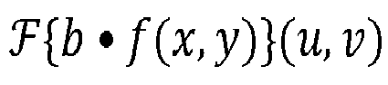
- F f x y u v • G u v may be expressed by a difference between F f x y u v • G ′ u v and F b • f x y u v .
- F f x y u v • G u v may be expressed by Equation 8 below through the inverse Fourier transform.
- G' ( u, v ) is a positive number
- the operation using the optical 4f system 100 may be possible; because b • f ( x,y ) is capable of being calculated by directly multiplying an input f ( x,y ) and a constant "b" together without using the optical 4f system 100, unlike Equation 4 that requires the operation using the optical 4f system 100 two times, the operation F ⁇ 1 F f x y u v • G ′ u v x y using the optical 4f system 100 may be required only once, and thus, the convolution operation may be optimized.
- F f x y u v • G u v may be calculated by using a difference between F f ′ x y u v • G ′ u v , F a u v • G ′ u v , and F ⁇ b • f ( x, y ) ⁇ ( u, v ) .
- F f x y u v • G u v may be expressed by Equation 10 below through the inverse Fourier transform.
- F ⁇ 1 F f x y u v • G u v x y may be incapable of being calculated directly through the optical 4f system 100; however, because f '( x,y ) ⁇ 0 and G' ( u, v ) ⁇ 0 , F ⁇ 1 F f x y u v • G ′ u v x y and F ⁇ 1 ⁇ F f a u v • G' ( u, v ) ⁇ ( x,y ) may be calculated through the optical 4f system 100, and b • f ( x,y ) may be calculated by directly multiplying an input f(x,y) and a constant "b" without using the optical 4f system 100.
- Equation 6 that requires the operation using the optical 4f system 100 four times, because only two operations ( F ⁇ 1 F f x y u v • G ′ u v x y and F ⁇ 1 F f a u v • G ′ u v x y ) using the optical 4f system 100 are required, the convolution operation may be extended to a negative number input as well as a positive number input, and the number of operations may be optimized.
- FIG. 6 is a flowchart illustrating an example of an operating method of the optical 4f system 100 according to an embodiment of the present disclosure. Below, the description will be given with reference to FIG. 1 together with FIG. 6 .
- the first lens 110 may receive input data from the object 10.
- the kernel 120 may perform the first Fourier transform on the input data
- the kernel 120 may generate learning data by performing calculation (e.g., a multiplication operation) on a result of the first Fourier transform and pattern data.
- the second lens 130 may generate result data by performing the second Fourier transform (e.g., inverse Fourier transform) on the learning data.
- the kernel 120 may correspond to a filter of the CNN, and an image indicated by the input data and an image indicated by the result data may be inverted images.
- the convolution operation using the optical 4f system may be performed on f ( x,y ) and G(u, v) including both a positive number and a negative number, and a result of the convolution operation may also include both a positive number and a negative number. As such, the following are obtained.
- f ( x,y ) is the first input image of the CNN or an input value of a previous CNN layer. Because there is a limitation condition that f ( x,y ) must always be a positive number, it is difficult to use the conventional optical 4f system in the artificial intelligence and machine learning fields such as CNN; however, according to an embodiment of the present disclosure, because the limitation associated with f ( x,y ) is removed, the optical 4f system may be applied to the CNN including a plurality of convolution layers.
- G ( u,v ) is an image pattern that is trained in the CNN.
- a learning result of the CNN may be excellent. Because there was a constraint condition that G ( u,v ) must always be a positive number, when a conventional optical 4f system is applied to the CNN, a CNN learning result may be degraded; however, according to an embodiment of the present disclosure, because the limitation associated with G(u, v) is removed, learning and inference results of the CNN may be improved when a variety of patterns are trained.
- a value generated in the conventional optical 4f system is always a positive number, some nonlinear functions may not operate properly, resulting in the reduction of CNN performance.
- some nonlinear functions such as a rectified linear unit (ReLU) acts as an identity function when an input value is positive, it is impossible to express a characteristic of the nonlinear function.
- ReLU rectified linear unit
- a multi-layer neural network operates only as a linear function, the multi-layer neural network performs only a role of a single-layer neural network.
- an image generated by an optical 4f system may be input to the ReLU function to perform CNN learning and inference.
- the optical 4f system is not limited to being used for the convolution operation and may be used for a variety of alternative purposes.
- the optical 4f system according to an embodiment of the present disclosure may be used in combination with many existing computing systems and devices including a processor.
- the processor may include a special purpose processing device such as an application-specific integrated circuit (ASIC), a programmable array logic (PAL), a programmable logic array (PLA), a programmable logic device (PLO), or a field programmable gate array (FPGA), or any other custom and/or programmable device.
- ASIC application-specific integrated circuit
- PAL programmable array logic
- PLA programmable logic array
- PLO programmable logic device
- FPGA field programmable gate array
- a computing device may also include storage devices such as a static RAM, a dynamic RAM, a ROM, a CD-ROM, a magnetic tape, an optical disk, a flash memory, a non-transitory computer readable medium, or any other machine readable medium.
- storage devices such as a static RAM, a dynamic RAM, a ROM, a CD-ROM, a magnetic tape, an optical disk, a flash memory, a non-transitory computer readable medium, or any other machine readable medium.
- an optical 4f system may be applied to a CNN including a plurality of convolution layers, more diverse image patterns may be trained, and thus, learning and reasoning results of the CNN may be improved.
- a convolution result value may also be output as various values including negative numbers, and thus, CNN learning and inference may be performed in conjunction with a ReLU-based nonlinear function.
Landscapes
- Engineering & Computer Science (AREA)
- Physics & Mathematics (AREA)
- Theoretical Computer Science (AREA)
- General Physics & Mathematics (AREA)
- Mathematical Physics (AREA)
- Software Systems (AREA)
- General Engineering & Computer Science (AREA)
- Health & Medical Sciences (AREA)
- Life Sciences & Earth Sciences (AREA)
- Artificial Intelligence (AREA)
- Biomedical Technology (AREA)
- Biophysics (AREA)
- Computing Systems (AREA)
- Data Mining & Analysis (AREA)
- Evolutionary Computation (AREA)
- General Health & Medical Sciences (AREA)
- Molecular Biology (AREA)
- Computational Linguistics (AREA)
- Multimedia (AREA)
- Optics & Photonics (AREA)
- Neurology (AREA)
- Computer Vision & Pattern Recognition (AREA)
- Medical Informatics (AREA)
- Complex Calculations (AREA)
Abstract
Description
- This application claims priority under 35 U.S.C. § 119 to
Korean Patent Application No. 10-2021-0185587 filed on December 23, 2021 10-2022-0173746 filed on December 13, 2022 - Embodiments of the present disclosure described herein relate to a convolution operation, and more particularly, relate to an optical 4f system performing extended convolution operations and an operating method thereof.
- A convolutional neural network (CNN) is a type of deep neural network that includes one or more convolution layers. The CNN provides good performance in image recognition, video recognition, image classification, medical image analysis, natural language processing, and time-series analysis, and fields to which the CNN is applied continue to expand.
- An optical 4f system refers a system that has a structure in which two lenses are paired and transfers an image from a first lens of one side to a second lens of an opposite side; when the first and second lenses have the same focal length of "f", a distance from an object plane (or an input plane) to the first lens is "f", a distance from the first lens to the second lens is 2f, and a distance from the second lens to an image plane (or an output plane) is "f". That is, a total length from the object plane to the image plane is 4f.
- Nowadays, the convolution operation using the optical 4f system is being actively researched. However, because an input and an output of the optical 4f system are proportional to the intensity of light but a value used in the convolution operation is based on the amplitude of light, it is necessary to correct the input and the output. Also, because the amplitude of light is expressed only by a positive number, when the convolution operation is performed only by using the optical 4f system without a separate auxiliary device, it is impossible to receive a value including a negative number.
- Embodiments of the present disclosure provide a method for extending a convolution operation of an optical 4f system such that a convolution operation is performed on an input including a negative number in the optical 4f system, an optical 4f system performing the extended convolution operation, and an operating method of the optical 4f system.
- According to an embodiment, an optical system includes a first lens that receives input data from an object, a kernel that performs a first Fourier transform on the input data and generates learning data by performing calculation on a result of the first Fourier transform and pattern data, and a second lens that generates result data by performing a second Fourier transform on the learning data, and the input data, the learning data, and the result data include both a positive number and a negative number.
- According to an embodiment, an operating method of an optical system which includes a first lens, a kernel, and a second lens includes receiving input data from an object through the first lens, performing a first Fourier transform on the input data through the kernel, generating learning data by performing calculation on a result of the first Fourier transform and pattern data, and generating result data by performing a second Fourier transform on the learning data, and the input data, the learning data, and the result data include both a positive number and a negative number.
- The above and other objects and features of the present disclosure will become apparent by describing in detail embodiments thereof with reference to the accompanying drawings.
-
FIG. 1 is a block diagram of an optical 4f system according to an embodiment of the present disclosure. -
FIG. 2 is a diagram illustrating a result of expressing values associated with an operation performed in an optical 4f system ofFIG. 1 through a light amplitude and a light intensity. -
FIG. 3 illustrates operation rules of Fourier transform and operation rules of inverse Fourier transform, which are used to extend a convolution operation. -
FIG. 4 illustrates theorems used for extension of a convolution operation. -
FIG. 5 illustrates theorems used for extension of an extended convolution operation. -
FIG. 6 is a flowchart illustrating an example of an operating method of an optical 4f system according to an embodiment of the present disclosure. - Below, embodiments of the present disclosure will be described in detail and clearly to such an extent that one skilled in the art easily carries out the present disclosure.
- In the detailed description, components described with reference to the terms "unit", "module", "block", "~er or ~or", etc. and function blocks illustrated in drawings will be implemented with software, hardware, or a combination thereof. For example, the software may be a machine code, firmware, an embedded code, and application software. For example, the hardware may include an electrical circuit, an electronic circuit, a processor, a computer, an integrated circuit, integrated circuit cores, a pressure sensor, an inertial sensor, a microelectromechanical system (MEMS), a passive element, or a combination thereof.
-
FIG. 1 is a diagram illustrating an example of anoptical 4f system 100 according to an embodiment of the present disclosure. Referring toFIG. 1 , theoptical 4f system 100 may include afirst lens 110, akernel 120, and asecond lens 130. Assuming that a focal length of each of thefirst lens 110 and thesecond lens 130 is "f', a distance between an object 10 and thefirst lens 110, a distance between thefirst lens 110 and thesecond lens 130, and a distance between thesecond lens 130 and animage 20 are "f", 2f, and "f"; in this case, a total of length may be 4f. - The
first lens 110 may receive input data f(x,y) from the object 10 and may perform a first Fourier transform at a location of thekernel 120, and thesecond lens 130 may perform a second Fourier transform. For example, thekernel 120 may serve as a filter between the first Fourier transform and the second Fourier transform and may include pattern data G(u,v) associated with learning. The convolution operation of theoptical 4f system 100 may be implemented by performing the Fourier transform continuously two times. That is, theoptical 4f system 100 may output theimage 20 corresponding to a result of the convolution operation of thekernel 120 with the object 10 through thelenses image 20 are inverted (or reverse) images. - In detail, f(x,y) may correspond to the first input image or an input value of a previous CNN layer, G(u, v) may correspond to an image pattern trained in the CNN, and

optical 4f system 100.
first lens 110, which corresponds to the transformation from the x-y plane to the u-v plane.


second lens 130 and may be expressed in the form of inverse Fourier transform for the convenience of equation expansion in the specification. -
FIG. 2 is a diagram illustrating a result of expressing values associated with an operation performed in theoptical 4f system 100 ofFIG. 1 through a light amplitude and a light intensity. All f(x,y) , G(u, v), and
optical 4f system 100 described above are equations based on the light amplitude, and an actual input value and actual output values of theoptical 4f system 100 are proportional to the light intensity. For example, the actual input value and the actual output values may be expressed in form of |f(x,y)|2, |G(u,v)|2, and
optical 4f system 100, and the convolution operation may then be performed. - That is, because the input value and the output values of two-dimensional data used in the convolution operation using the
optical 4f system 100 are based on the light amplitude value, limitations f(x,y) ≥ 0, G (u, v) ≥ 0, and
-
FIG. 3 illsutrates operation rules FT1 and FT2 of Fourier transform and operation rules IFT1 and IFT2 of inverse Fourier transform, which are used to extend a convolution operation. InFIG. 3 , an operator "•" represents a multiplication operation, and an operator "∗" represents a convolution operation. Operation rules of the Fourier transform include the homogeneity FT1 indicating that an output magnitude is proportional to an input magnitude, the additivity FT2 indicating that a total result when plural input signals are added is equal to a result of adding results of individual input signals, and the Fourier transform FT3 for convolution indicating that the convolution operation in the x-y plane is expressed by a multiplication operation in the u-v plane. Operation rules of the inverse Fourier transform include the inverse property IFT1 indicating that an original input value is obtained by performing the inverse Fourier transform on a result of the Fourier transform and the distributive property for addition IFT2. -
FIG. 4 illustrates theorems used for extension of a convolution operation. With regard to f(x,y) in the x-y plane, a first theorem indicates that an input signal is expressed by a difference between signals f 1(x,y) ≥ 0 and f 2(x, y) ≥ 0 being two arbitrary different positive numbers; with regard to G(u, v) in the u-v plane, a second theorem indicates that an input signal is expressed by a difference between signals G 1 (u, v) ≥ 0 and G2 (u, v) ≥ 0 being two arbitrary different positive numbers. - First, the way to remove the limitation associated with f(x,y) will be described. Assuming an arbitrary f(x,y) in which there is not limitation condition of a positive number or a negative number, according to the first theorem of
FIG. 4 , f 1(x,y)and f 2(x, y) that satisfy f(x,y) = f 1(x, y) - f 2(x, y) and in which there is a limitation condition of a positive number may certainly exist (f 1(x, y) ≥ 0 and f 2(x, y) ≥ 0). Also, because the additivity FT2 ofFIG. 3 is applied to the Fourier transform,
Equation 1 below.
- That is,


FIG. 3 is applied,Equation 1 above may be expressed likeEquation 2 below through the inverse Fourier transform.
- Herein, as described above, in the case of f(x,y), because it is assumed that there is no special limitation condition,

optical 4f system 100 ofFIG. 1 . However, because f 1(x, y) and f2 (x, y) have a positive number limitation condition, both

Equation 2 above may be calculated through theoptical 4f system 100. Accordingly, when an arbitrary f(x, y) and G(u, v) being a positive number are given, a value of


optical 4f system 100. - Next, the way to remove the limitation associated with G (u, v) will be described. Assuming an arbitrary G (u, v) in which there is no limitation condition of a positive number or a negative number, according to the second theorem of
FIG. 4 , G 1(u, v) and G2 (u, v) that satisfy G(u, v) = G 1(u, v) - G 2(u, v) and have a positive number limitation condition may certainly exist (G 1(u, v) ≥ 0 and G 2(u, v) ≥ 0). Also, because the additivity FT2 ofFIG. 3 is applied to the Fourier transform,
Equation 3 below.
- That is,


FIG. 3 is applied,Equation 3 above may be expressed likeEquation 4 below through the inverse Fourier transform.
- According, when f(x,y) being a positive number and an arbitrary G(u, v) are given, a value of



optical 4f system 100. - Now, the way to remove all the limitations associated with f(x,y) and G (u, v) will be described. According to the first theorem and the second theorem of
FIG. 4 , an arbitrary f(x,y) in which there is no limitation condition may satisfy f(x, y) = f 1(x, y) - f 2(x, y) (f 1(x, y) ≥ 0 and f2 (x, y) ≥ 0 ), and an arbitrary G(u, v) in which there is no limitation condition may satisfy G(u, v) = G 1(u, v) - G2 (u, v) (G 1(u, v) ≥ 0 and G 2(u, v) ≥ 0); in this case, when the additivity FT2 ofFIG. 3 is applied,

- Now, when the inverse property IFT1 of
FIG. 3 is applied, a result of Equation 5 above may be expressed by Equation 6 below through the inverse Fourier transform.
- Accordingly,

optical 4f system 100 but may be expressed through f 1(x, y) ≥ 0, f 2(x, y) ≥ 0, G 1(u, v) ≥ 0, and G 2(u, v) ≥ 0 like Equation 6 above. Therefore,


optical 4f system 100 four times and then adding differences thereof. As such, the limitations associated with f(x, y) and G(u, v) may be removed, and the convolution operation using theoptical 4f system 100 may be extended. - Until now, a method in which the convolution operation of the
optical 4f system 100 ofFIG. 1 is extended by removing positive number limitations associated with f(x, y) and G(u, v) is described. However, referring to Equation 6 above, the convolution operation using theoptical 4f system 100 should be performed four times to draw an operation result which is not limited to only a positive number. Below, the way to optimize an extended convolution operation by using the number of necessary convolution operations will be described. -
FIG. 5 illustrates theorems used for extension of an extended convolution operation. With regard to the x-y plane f(x, y), a third theorem indicates that an input signal for G(u, v) is expressed by a difference between a signal f`(x, y) ≥ 0 being an arbitrary positive number and a positive constant (a ≥ 0 and b ≥ 0); with regard to the u-v plane, a fourth theorem indicates that an input signal for G(u, v) is expressed by a difference between a signal G'(u, v) ≥ 0 being an arbitrary positive number and a positive constant (a ≥ 0 and b ≥ 0). - First, the way to optimize a convolution operation for an arbitrary G(u, v) through the fourth theorem will be described. In detail, f(x,y) may be optimized similarly by applying the third theorem, and thus, additional description will be omitted to avoid redundancy. After the optimization of G(u,v) is described, the way to optimize both f(x,y) and G(u, v) will be described.
- According to the fourth theorem, because G(u, v) is expressed like G'(u, v) - b(G'(u, v) ≥ 0, b ≥ 0),

FIG. 3 .
- That is,




- Because G'(u, v) is a positive number, the operation using the
optical 4f system 100 may be possible; because b • f(x,y) is capable of being calculated by directly multiplying an input f(x,y) and a constant "b" together without using theoptical 4f system 100, unlikeEquation 4 that requires the operation using theoptical 4f system 100 two times, the operation
optical 4f system 100 may be required only once, and thus, the convolution operation may be optimized. - Finally, how to optimize arbitrary f(x, y) and G(u, v) will be described. According to the fourth theorem, because f(x,y) is capable of being expressed like f'(x, y) - a(f'(x, y) ≥ 0, a ≥ 0) and G(u, v) is capable of being expressed like G'(u, v) - b (G'(u, v) ≥ 0, b ≥ 0),

FIG. 3 together.
- That is,


FIG. 3 are applied,

- Because arbitrary f(x,y) and G(u,v) are not limited to a positive number,

optical 4f system 100; however, because f'(x,y) ≥ 0 and G'(u, v) ≥ 0 ,

optical 4f system 100, and b • f(x,y) may be calculated by directly multiplying an input f(x,y) and a constant "b" without using theoptical 4f system 100. Therefore, unlike Equation 6 that requires the operation using theoptical 4f system 100 four times, because only two operations

optical 4f system 100 are required, the convolution operation may be extended to a negative number input as well as a positive number input, and the number of operations may be optimized. -
FIG. 6 is a flowchart illustrating an example of an operating method of theoptical 4f system 100 according to an embodiment of the present disclosure. Below, the description will be given with reference toFIG. 1 together withFIG. 6 . - In operation S110, the
first lens 110 may receive input data from the object 10. In operation S120, thekernel 120 may perform the first Fourier transform on the input data, and in operation S130, thekernel 120 may generate learning data by performing calculation (e.g., a multiplication operation) on a result of the first Fourier transform and pattern data. In operation S140, thesecond lens 130 may generate result data by performing the second Fourier transform (e.g., inverse Fourier transform) on the learning data. Herein, thekernel 120 may correspond to a filter of the CNN, and an image indicated by the input data and an image indicated by the result data may be inverted images. - In conclusion, through embodiments of the present disclosure, the convolution operation using the optical 4f system may be performed on f(x,y) and G(u, v) including both a positive number and a negative number, and a result of the convolution operation may also include both a positive number and a negative number. As such, the following are obtained.
- As described with reference to
FIG. 1 , f(x,y) is the first input image of the CNN or an input value of a previous CNN layer. Because there is a limitation condition that f(x,y) must always be a positive number, it is difficult to use the conventional optical 4f system in the artificial intelligence and machine learning fields such as CNN; however, according to an embodiment of the present disclosure, because the limitation associated with f(x,y) is removed, the optical 4f system may be applied to the CNN including a plurality of convolution layers. - G(u,v) is an image pattern that is trained in the CNN. When there are provided a variety of patterns that is capable of being trained in the machine learning field, a learning result of the CNN may be excellent. Because there was a constraint condition that G(u,v) must always be a positive number, when a conventional optical 4f system is applied to the CNN, a CNN learning result may be degraded; however, according to an embodiment of the present disclosure, because the limitation associated with G(u, v) is removed, learning and inference results of the CNN may be improved when a variety of patterns are trained.
- Also, because a value generated in the conventional optical 4f system is always a positive number, some nonlinear functions may not operate properly, resulting in the reduction of CNN performance. For example, because a nonlinear function such as a rectified linear unit (ReLU) acts as an identity function when an input value is positive, it is impossible to express a characteristic of the nonlinear function. In this case, because a multi-layer neural network operates only as a linear function, the multi-layer neural network performs only a role of a single-layer neural network. According to an embodiment of the present disclosure, because the limitations associated with a convolution result are removed, an image generated by an optical 4f system according to an embodiment of the present disclosure may be input to the ReLU function to perform CNN learning and inference.
- The optical 4f system according to embodiments of the present disclosure is not limited to being used for the convolution operation and may be used for a variety of alternative purposes. In addition, the optical 4f system according to an embodiment of the present disclosure may be used in combination with many existing computing systems and devices including a processor. For example, the processor may include a special purpose processing device such as an application-specific integrated circuit (ASIC), a programmable array logic (PAL), a programmable logic array (PLA), a programmable logic device (PLO), or a field programmable gate array (FPGA), or any other custom and/or programmable device. A computing device may also include storage devices such as a static RAM, a dynamic RAM, a ROM, a CD-ROM, a magnetic tape, an optical disk, a flash memory, a non-transitory computer readable medium, or any other machine readable medium.
- According to an embodiment of the present invention, as an optical 4f system may be applied to a CNN including a plurality of convolution layers, more diverse image patterns may be trained, and thus, learning and reasoning results of the CNN may be improved.
- Also, according to an embodiment of the present invention, a convolution result value may also be output as various values including negative numbers, and thus, CNN learning and inference may be performed in conjunction with a ReLU-based nonlinear function.
- While the present disclosure has been described with reference to embodiments thereof, it will be apparent to those of ordinary skill in the art that various changes and modifications may be made thereto without departing from the spirit and scope of the present disclosure as set forth in the following claims.
Claims (16)
- An optical system comprising:a first lens configured to receive input data from an object;a kernel configured to perform a first Fourier transform on the input data and to generate learning data by performing calculation on a result of the first Fourier transform and pattern data; anda second lens configured to generate result data by performing a second Fourier transform on the learning data,wherein the input data, the learning data, and the result data include both a positive number and a negative number.
- The optical system of claim 1, wherein phases of an image represented by the input data and an image represented by the result data are opposite.
- The optical system of claim 1 or 2, wherein the kernel corresponds to a filter of a convolutional neural network (CNN).
- The optical system of one of claims 1 to 3, wherein the learning data are calculated by Equation 1:


- The optical system of claim 4, wherein the result data are calculated by Equation 2:

- The optical system of one of claims 1 to 5, wherein the learning data are calculated by Equation 3:


- The optical system of claim 6, wherein the result data are calculated by Equation 4:

- The optical system of one of claims 1 to 7, wherein the result data are input to a ReLU (Rectified Linear Unit) function.
- An operating method of an optical system which includes a first lens, a kernel, and a second lens, the method comprising:receiving input data from an object through the first lens;performing a first Fourier transform on the input data through the kernel;generating learning data by performing calculation on a result of the first Fourier transform and pattern data; andgenerating result data by performing a second Fourier transform on the learning data,wherein the input data, the learning data, and the result data include both a positive number and a negative number.
- The method of claim 9, wherein phases of an image represented by the input data and an image represented by the result data are opposite.
- The method of claim 9 or 10, wherein the kernel corresponds to a filter of a convolutional neural network (CNN).
- The method of one of claims 9 to 11, wherein the generating of the learning data includes generating the learning data based on Equation 1:


- The method of claim 12, wherein the generating of the result data includes generating the result data based on Equation 2:

- The method of one of claims 9 to 13, wherein the generating of the learning data includes generating the learning data based on Equation 3:


- The method of claim 14, wherein the generating of the result data includes generating the result data based on Equation 4:

- The method of one of claims 9 to 15, further comprising:
inputting the result data to a ReLU (Rectified Linear Unit) function.
Applications Claiming Priority (2)
| Application Number | Priority Date | Filing Date | Title |
|---|---|---|---|
| KR20210185587 | 2021-12-23 | ||
| KR1020220173746A KR102792378B1 (en) | 2021-12-23 | 2022-12-13 | OPTICAL 4f SYSTEM PERFORMING EXTENDED CONVOLUTION OPERATION AND OPERATING METHOD THEREOF |
Publications (1)
| Publication Number | Publication Date |
|---|---|
| EP4202778A1 true EP4202778A1 (en) | 2023-06-28 |
Family
ID=84569546
Family Applications (1)
| Application Number | Title | Priority Date | Filing Date |
|---|---|---|---|
| EP22215986.5A Pending EP4202778A1 (en) | 2021-12-23 | 2022-12-22 | Optical 4f system performing extended convolution operation and operating method thereof |
Country Status (2)
| Country | Link |
|---|---|
| US (1) | US20230206620A1 (en) |
| EP (1) | EP4202778A1 (en) |
Family Cites Families (7)
| Publication number | Priority date | Publication date | Assignee | Title |
|---|---|---|---|---|
| US6424449B1 (en) * | 1999-04-19 | 2002-07-23 | Olympus Optical Co., Ltd. | Optical information processing apparatus for image processing using a reflection type spatial light modulator |
| US7228005B1 (en) * | 2002-06-17 | 2007-06-05 | National Security Technologies, Llc | Adaptive wiener image restoration kernel |
| DE102009015393B3 (en) * | 2009-03-20 | 2010-09-02 | Carl Zeiss Smt Ag | Measuring method and measuring system for measuring birefringence |
| JP6238687B2 (en) * | 2013-11-12 | 2017-11-29 | キヤノン株式会社 | Mask pattern creation method, optical image calculation method |
| US11200487B1 (en) * | 2016-12-30 | 2021-12-14 | X Development Llc | Optical processing system |
| GB2573171B (en) * | 2018-04-27 | 2021-12-29 | Optalysys Ltd | Optical processing systems |
| WO2020102204A1 (en) * | 2018-11-12 | 2020-05-22 | Massachusetts Institute Of Technology | Large-scale artificial neural-network accelerators based on coherent detection and optical data fan-out |
-
2022
- 2022-12-21 US US18/085,716 patent/US20230206620A1/en active Pending
- 2022-12-22 EP EP22215986.5A patent/EP4202778A1/en active Pending
Non-Patent Citations (2)
| Title |
|---|
| SHURUI LI ET AL: "Channel Tiling for Improved Performance and Accuracy of Optical Neural Network Accelerators", ARXIV.ORG, CORNELL UNIVERSITY LIBRARY, 201 OLIN LIBRARY CORNELL UNIVERSITY ITHACA, NY 14853, 15 January 2021 (2021-01-15), XP081859707 * |
| WU QIUHAO ET AL: "Multi-layer optical Fourier neural network based on the convolution theorem", AIP ADVANCES, AMERICAN INSTITUTE OF PHYSICS, 2 HUNTINGTON QUADRANGLE, MELVILLE, NY 11747, vol. 11, no. 5, 11 May 2021 (2021-05-11), XP012256451, DOI: 10.1063/5.0055446 * |
Also Published As
| Publication number | Publication date |
|---|---|
| US20230206620A1 (en) | 2023-06-29 |
Similar Documents
| Publication | Publication Date | Title |
|---|---|---|
| US10296827B2 (en) | Data category identification method and apparatus based on deep neural network | |
| JP7103240B2 (en) | Object detection and recognition devices, methods, and programs | |
| US20220083863A1 (en) | System and method for teaching compositionality to convolutional neural networks | |
| CN108154145B (en) | Method and device for detecting position of text in natural scene image | |
| DE102019000171A1 (en) | Digital environment for the location of semantic classes | |
| Han et al. | Efficient Markov feature extraction method for image splicing detection using maximization and threshold expansion | |
| JP6348431B2 (en) | Image processing method and image processing apparatus | |
| KR102095152B1 (en) | A method of recognizing a situation and apparatus performing the same | |
| EP3951703B1 (en) | Method and apparatus with image processing | |
| CN119540518A (en) | Real-time salient object detection in images and videos | |
| Balonin et al. | Mersenne-Walsh matrices for image processing | |
| WO2020255224A1 (en) | Abnormality detection device, learning device, abnormality detection method, learning method, abnormality detection program, and learning program | |
| CN112633260A (en) | Video motion classification method and device, readable storage medium and equipment | |
| US20190347541A1 (en) | Apparatus, method and computer program product for deep learning | |
| US12394028B2 (en) | System and method with masking and inpainting strategy for generic defense against patch attacks | |
| US20230206620A1 (en) | OPTICAL 4f SYSTEM PERFORMING EXTENDED CONVOLUTION OPERATION AND OPERATING METHOD THEREOF | |
| US20170300776A1 (en) | Image identification system | |
| Davis et al. | Experimental implementation of a virtual optical beam propagator system based on a Fresnel diffraction algorithm | |
| KR102792378B1 (en) | OPTICAL 4f SYSTEM PERFORMING EXTENDED CONVOLUTION OPERATION AND OPERATING METHOD THEREOF | |
| CN119671851A (en) | Remote sensing image super-resolution reconstruction method and system based on residual hierarchical Transformer | |
| EP4468232A1 (en) | Image processing device and method for operating same | |
| KR101596590B1 (en) | Classification method and apparatus with incremental learning and local adjustment | |
| JP2010182167A (en) | Image processor and image processing method | |
| US20250157185A1 (en) | Information processing apparatus and control method therefor | |
| CN107341826A (en) | The method and device of user equipment and image procossing |
Legal Events
| Date | Code | Title | Description |
|---|---|---|---|
| PUAI | Public reference made under article 153(3) epc to a published international application that has entered the european phase |
Free format text: ORIGINAL CODE: 0009012 |
|
| STAA | Information on the status of an ep patent application or granted ep patent |
Free format text: STATUS: THE APPLICATION HAS BEEN PUBLISHED |
|
| AK | Designated contracting states |
Kind code of ref document: A1 Designated state(s): AL AT BE BG CH CY CZ DE DK EE ES FI FR GB GR HR HU IE IS IT LI LT LU LV MC ME MK MT NL NO PL PT RO RS SE SI SK SM TR |
|
| STAA | Information on the status of an ep patent application or granted ep patent |
Free format text: STATUS: REQUEST FOR EXAMINATION WAS MADE |
|
| 17P | Request for examination filed |
Effective date: 20240102 |
|
| RBV | Designated contracting states (corrected) |
Designated state(s): AL AT BE BG CH CY CZ DE DK EE ES FI FR GB GR HR HU IE IS IT LI LT LU LV MC ME MK MT NL NO PL PT RO RS SE SI SK SM TR |