EP4202765A1 - Method and system for counting bakeable food products - Google Patents
Method and system for counting bakeable food products Download PDFInfo
- Publication number
- EP4202765A1 EP4202765A1 EP22215325.6A EP22215325A EP4202765A1 EP 4202765 A1 EP4202765 A1 EP 4202765A1 EP 22215325 A EP22215325 A EP 22215325A EP 4202765 A1 EP4202765 A1 EP 4202765A1
- Authority
- EP
- European Patent Office
- Prior art keywords
- product
- inspection area
- food products
- processor module
- captured image
- Prior art date
- Legal status (The legal status is an assumption and is not a legal conclusion. Google has not performed a legal analysis and makes no representation as to the accuracy of the status listed.)
- Pending
Links
- 235000013305 food Nutrition 0.000 title claims abstract description 34
- 238000000034 method Methods 0.000 title claims abstract description 31
- 238000007689 inspection Methods 0.000 claims abstract description 30
- 230000003287 optical effect Effects 0.000 claims abstract description 18
- 238000006243 chemical reaction Methods 0.000 claims description 7
- 230000010339 dilation Effects 0.000 claims description 4
- 230000003628 erosive effect Effects 0.000 claims description 4
- 230000008569 process Effects 0.000 description 18
- 238000004519 manufacturing process Methods 0.000 description 13
- 238000012545 processing Methods 0.000 description 8
- 238000004891 communication Methods 0.000 description 7
- 230000009466 transformation Effects 0.000 description 5
- 239000002184 metal Substances 0.000 description 4
- 238000001514 detection method Methods 0.000 description 3
- 239000012535 impurity Substances 0.000 description 3
- 238000004458 analytical method Methods 0.000 description 2
- 230000005540 biological transmission Effects 0.000 description 2
- 238000010411 cooking Methods 0.000 description 2
- 230000007547 defect Effects 0.000 description 2
- 238000003908 quality control method Methods 0.000 description 2
- 238000000844 transformation Methods 0.000 description 2
- 241000196324 Embryophyta Species 0.000 description 1
- 235000011034 Rubus glaucus Nutrition 0.000 description 1
- 244000235659 Rubus idaeus Species 0.000 description 1
- 235000009122 Rubus idaeus Nutrition 0.000 description 1
- 230000006978 adaptation Effects 0.000 description 1
- 238000013473 artificial intelligence Methods 0.000 description 1
- 210000000988 bone and bone Anatomy 0.000 description 1
- 238000004883 computer application Methods 0.000 description 1
- 239000000356 contaminant Substances 0.000 description 1
- 238000010586 diagram Methods 0.000 description 1
- 238000006073 displacement reaction Methods 0.000 description 1
- 230000005672 electromagnetic field Effects 0.000 description 1
- 238000005516 engineering process Methods 0.000 description 1
- 238000011156 evaluation Methods 0.000 description 1
- 230000008570 general process Effects 0.000 description 1
- 239000011521 glass Substances 0.000 description 1
- 229910052500 inorganic mineral Inorganic materials 0.000 description 1
- 238000009434 installation Methods 0.000 description 1
- 230000010354 integration Effects 0.000 description 1
- 238000012423 maintenance Methods 0.000 description 1
- 238000007726 management method Methods 0.000 description 1
- 239000011707 mineral Substances 0.000 description 1
- 238000007639 printing Methods 0.000 description 1
- 239000000523 sample Substances 0.000 description 1
- 238000013515 script Methods 0.000 description 1
- 238000001228 spectrum Methods 0.000 description 1
- 239000004575 stone Substances 0.000 description 1
- 238000005303 weighing Methods 0.000 description 1
Images


Classifications
-
- G—PHYSICS
- G06—COMPUTING; CALCULATING OR COUNTING
- G06M—COUNTING MECHANISMS; COUNTING OF OBJECTS NOT OTHERWISE PROVIDED FOR
- G06M7/00—Counting of objects carried by a conveyor
-
- G—PHYSICS
- G06—COMPUTING; CALCULATING OR COUNTING
- G06M—COUNTING MECHANISMS; COUNTING OF OBJECTS NOT OTHERWISE PROVIDED FOR
- G06M7/00—Counting of objects carried by a conveyor
- G06M7/02—Counting of objects carried by a conveyor wherein objects ahead of the sensing element are separated to produce a distinct gap between successive objects
- G06M7/04—Counting of piece goods, e.g. of boxes
Definitions
- the present invention relates to the technical field of quality control on food product production lines and, more specifically, to computer vision systems for food products to be baked for the automatic counting and production control thereof.
- Mass production poses a challenge in terms of process supervision, control and management, among other problems. Although many stages of the production chain are automated, other tasks that are among the simplest are usually still carried out manually, which, in addition to the natural errors introduced by human intervention, entails an interruption in the information chain that feeds the control systems that are increasingly widespread in the industry, based on Big Data technologies and artificial intelligence.
- mass-produced bakeable food products under very specific manufacturing parameters such as baking time, are continuously introduced by means of conveyor belts into a baking module.
- This process usually requires control personnel to confirm correct operation, which is done visually (with the accuracy that the operator can guarantee) or, sometimes, it is directly omitted and quality control of the already baked product is postponed. In both cases, the efficiency and ability to respond to errors is low.
- the present invention describes, in a first aspect, a method for counting bakeable food products that comprises the following steps:
- applying, by the processor module, an HSV conversion to the captured image is envisaged. More specifically, one embodiment envisages applying, by the processor module, a conversion to black and white of the captured image. More specifically, one embodiment comprises applying, by the processor module, a colour mask on the captured image which eliminates any intermediate value between black and white.
- the colour transformations allow the background to be removed, which results in a simpler and better-quality image processing.
- the processing of the images further comprises applying, by the processor module, a blur filter on the captured image. More specifically, one of the embodiments envisages applying, by the processor module, an erosion filter on the captured image. More specifically, one of the embodiments envisages applying, by the processor module, a dilation filter on the captured image.
- the filters applied to the captured images make it possible to eliminate small defects in the conversion or enhance the shape of the product for better definition.
- the pre-established minimum threshold of identified pixels to determine the presence of the product is set to at least one third of the width of the captured image.
- the presence of a product in the inspection area if the number of identified pixels is greater than a pre-established minimum threshold, it must also be verified that the number of identified pixels is greater than said threshold in a certain number of successive readings.
- the presence of the product is correct and is not due to a false positive caused by some impurity or loose paste stain on the conveyor belt.
- the present invention relates to a system for counting bakeable food products, which comprises the following elements:
- an LED lighting module arranged to illuminate the inspection area is envisaged.
- the system is independent of external lighting conditions and can work under more homogeneous conditions.
- One specific embodiment of the invention further comprises a conveyor belt for conveying bakeable food products to an oven, wherein the optical sensor is arranged on the conveyor belt along an axis perpendicular to the conveying direction. More specifically, it is envisaged that the optical sensor comprises hinged fastening means that can be coupled to a support structure, to adjust the inspection area along a line perpendicular to the conveying direction.
- the processor module is a Raspberry Pi computer board and the optical sensor is a Raspberry Pi camera module.
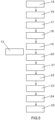
- Figure 1 shows a perspective view of one of the preferred embodiments of the system of the invention for recognising and counting bakeable food products ( 1 ) arranged on a conveyor belt ( 2 ).
- Figure 2 shows a perspective view of one of the preferred embodiments of the system of the invention for recognising and counting bakeable food products ( 5 ) arranged on a conveyor belt ( 6 ).
- a hinged part ( 7 ) fastens the casing ( 3 ) to a support structure ( 8 ), so that the inclination of the casing can be oriented and thereby adjust the image captured by the optical sensor and, therefore, the inspection area.
- Figure 3 shows a perspective view of one of the preferred embodiments of the system of the invention for recognising and counting bakeable food products arranged on a conveyor belt.
- the casing also has an LED lighting device ( 9 ).
- a guide system ( 10 ) can be used to allow longitudinal displacements of the casing along the guide ( 10 ) to vary the inspection area on different points of the conveyor belt.
- the casing can be fastened by means of screws to a fixed element of the structure.
- the casing can be coupled to a rod or bar, with a square or round section, as long as they allow the casing to be displaced transversely to the conveying direction of the conveyor belt.
- the LED lighting module is powered by the GPIO bus at 3.3V or 5V, depending on the needs, or even by an external power supply. With the connections made, the casing is placed in the inspection area for its operation.
- the operation of the present invention is generally based on the fact that, after performing an HSV conversion of the image by applying colour filters, blurring, eroding, dilation of the pixels and their conversion to black and white, the pixels in a certain area are counted and, after a minimum margin of pixels has been exceeded, the determination is made that there is a product in said area and a product counter is updated.
- Figure 4 schematically shows the main functional blocks of the invention, according to the main process. Following the flow chart represented, this process begins with the capture stage ( 11 ), in which the optical sensor acquires the images of the products; this is followed by a processing stage ( 12 ) for processing the captured images; after processing, a search stage ( 13 ) for searching for the product in the images occurs; and finally, a last stage of information transmission ( 14 ) is carried out.
- Figure 5 outlines the steps of the processing stage ( 12 ) according to one of the embodiments wherein, once there is an image capture ( 15 ), an inspection area ( 16 ) is defined in which the product is to be searched. In general, the inspection area should be wide enough to accommodate a product, or a large part of it, preferably defined perpendicular to the product conveying line.
- a first transformation of the image from RGB to HSV is performed ( 17 )
- a colour mask is applied ( 18 ) so that any colour that does not fall within the given spectrum tends to 0 (black) and the rest tends to 1 (white), which will give a better contrast between product and background
- a second transformation is applied to the resulting greyscale image ( 19 ). These colour space transformations will allow the background of the image to be removed.
- a first blur or distortion filter ( 20 ), which blurs the image and eliminates small gaps in the product, allowing the product's transformation to black and white ( 21 ) to be more homogeneous; a second erosion filter ( 22 ), which eliminates loose pixels that do not correspond to the product image, making it possible to eliminate colour impurities in the background; and a third dilation filter ( 23 ), which increases the size of the white areas, contributing to a better marking of the product and a greater number of white pixels. After this process, only white pixels remain in the processed image, which correspond to the food product.
- An inspection area that is more adjusted than the initial area is defined ( 24 ) and finally, the white pixels in the image in this adjusted inspection area are counted ( 25 ) to determine whether or not they are greater than a pre-established minimum threshold, which will define in the next stage whether or not the presence of the product in the image is confirmed.
- a minimum threshold of white pixels can be established to determine the presence of the product close to the width of the image.
- a value of at least a third or half of the width of the image is typically used to ensure that there will always be a number of pixels that ensures the presence of the product, avoiding failures due to deformation or poor positioning of the product prior to the image capture.
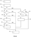
- Figure 6 outlines the search stage ( 13 ) according to one of the embodiments.
- the search for the product basically consists of evaluating whether certain requirements are met to determine that there is a product ( 29 ), which in this case are: exceeding a pre-established minimum number of pixels ( 26 ), exceeding a pre-established minimum number of readings ( 27 ) and exceeding a minimum time between product rows ( 28 ).
- the minimum number of readings is the number of successive times that the white pixel count must be greater than the threshold. It is established to avoid erroneous product detections caused by impurities or loose paste stains on the conveyor belt.
- the requirement of establishing a minimum time between rows seeks to avoid gaps within one same product and to avoid counting the same product twice. Additionally, one more criterion can be added to verify that, prior to detecting the presence of the current product, a gap has been detected ( 30 ) and, if so, the product counter is updated by one unit ( 31 ) and the search is concluded ( 32 ). To detect gaps, the flow chart takes a path that diverges from product detection.
- the last stage of information transmission relates to configuring the entire loop of the diagram to determine whether data is to be sent, when it is going to be sent and how it is going to be sent.
- the area where the camera is located can be defined and it can be coded according to factory parameters. For example, selecting when to send the information can be configured, as long as there is a minimum time gap between products, designed, for example, for discontinuous product cans or if the number of counted units is greater than the minimum entered. It can also be configured to send the histogram (total number of white pixels during the entire product selection process in all readings) for an analysis of results and subsequent adjustment of values and the sending of results by UDP protocol or for execution by a web page.
- Figure 7 represents, by way of example, one of the images processed in one of the embodiments of the present invention to detect the presence and subsequently count bakeable food products.
- the bottom ( 36 ) is represented completely in black (although in the figure it has not been coloured to optimise ink in a possible reproduction on paper), offering the maximum possible contrast with the white pixels, which represent the areas of the image occupied by the products ( 37 ).
- FIG. 8 schematically represents the hardware and software structure of said installation, wherein all the control devices ( 80 ) distributed throughout the factory are located at the base and they communicate through their corresponding communication controllers ( 81 ) with a central server ( 82 ).
- the central server in communication with the cloud ( 83 ), allows access from different platforms ( 84, 85, 86 ) to use the information collected at the source by the control devices in tasks of supervising, display, data logging, etc.
- a PLC programmable logic controller
- a PLC programmable logic controller
- programmable automaton is an industrial computer that processes all the data of a machine, such as sensors, buttons, timers and any input signal, to subsequently control the actuators (pistons, motors, valves, etc.) and thus be able to control any industrial process automatically.
- control devices ( 80 ) deployed by a smart factory with a computer vision system such as the one described by the present invention can integrate scales for different types of weighing during the process; metal detectors to alert the user of any metal objects intercepted by the detector's electromagnetic field, which automatically ejects the product from the production line; X-ray systems for detecting dense contaminants such as glass, metal, mineral stone, calcified bone and high-density plastic, regardless of their size, shape or location inside the product, which is automatically ejected in the case of detection following parallel operation to the metal detector; high-precision dynamic weighers to verify the weight of the product on the conveyor belt, unaffected by the vibrations of said belt and reliable so as to properly discard incomplete products at high speed; expiry date printers for continuously printing an expiry date on products; or Raspberry Pi boards with various functions adapted to each situation, such as temperature probes, computer vision or integration of new devices.
- the communication controllers ( 81 ) are necessary to establish communication between the different control devices and the central server ( 83 ), for example of the OPC Unified Architecture type. Specific communication drivers are used for each piece of equipment to be able to recognise which devices are connected and thus make optimal use of them. To use the data collected by the control devices in the form of variables or registers on different data logging or display and supervising platforms, all the devices send the data via these drivers to the OPC UA server, wherein each driver is given a different configuration to achieve successful communication on one same platform with all the connected devices.
- the platforms from which a user can access and process the information initially collected by the control devices can comprise, for example, a SCADA system ( 84 ), which is an industrial automation and control tool used in production processes that can control, supervise, collect data, analyse data and generate reports remotely through a computer application. Its main function is to evaluate the data in order to correct possible errors.
- SCADA system 84
- an alarm system in which certain variables to be controlled are received, whether they come from a PLC, databases or other integrated systems, where scripts can be created with conditions that, when met, activate an alarm. Selected users can be notified of the alarms via e-mail or telephone, although a sound or light system that can more immediately capture the attention of operators can also be implemented.
- a smart factory like the one described herein also needs a database ( 86 ) between the platforms.
- These factories often have an enterprise resource planning (ERP) system to address the business needs from a process standpoint and to integrate company-wide information systems.
- ERP enterprise resource planning
- the control devices ( 80 ) directly communicate with the ERP, through TCP, sending data that will be stored in a table of said database ( 86 ).
- a scale would send the line on which it is working, the ordinal of said scale, the moment of sending, the value of the weight, the established maximum and minimum, and all the information that the user needs to save.
- Communication with this database ( 86 ) is two-way, such that variables can be created from a query to the database and these variables can be processed, for example, in a SCADA system as described above. Therefore, a log of all the necessary information is obtained to subsequently process it according to the needs.
Abstract
Description
- The present invention relates to the technical field of quality control on food product production lines and, more specifically, to computer vision systems for food products to be baked for the automatic counting and production control thereof.
- Currently, the productive resources in the food industry seek to achieve the greatest possible efficiency, but without having to renounce high product customisation, flexibility and quick adaptation to different scenarios in a large production plant, which are provided by the infrastructure.
- Mass production poses a challenge in terms of process supervision, control and management, among other problems. Although many stages of the production chain are automated, other tasks that are among the simplest are usually still carried out manually, which, in addition to the natural errors introduced by human intervention, entails an interruption in the information chain that feeds the control systems that are increasingly widespread in the industry, based on Big Data technologies and artificial intelligence.
- Specifically, mass-produced bakeable food products, under very specific manufacturing parameters such as baking time, are continuously introduced by means of conveyor belts into a baking module. This process usually requires control personnel to confirm correct operation, which is done visually (with the accuracy that the operator can guarantee) or, sometimes, it is directly omitted and quality control of the already baked product is postponed. In both cases, the efficiency and ability to respond to errors is low.
- Faced with this problem, it would be desirable to carry out an immediate and automatic count of the products in order to supervise the process, detect their presence and observe, for example, that the products move at the expected speed, that they are properly distributed along the conveyor belt, that they receive the expected cooking and, in general, that errors in the cooking process are avoided by detecting and counting all the products.
- Therefore, a solution is needed in the state of the art to give continuity to smart production systems and offer a computer vision system that allows bakeable food products to be controlled and supervised in a simple, efficient and integrated manner on a production line.
- To achieve the objectives of implementing smart production systems and avoiding the aforementioned drawbacks, the present invention describes, in a first aspect, a method for counting bakeable food products that comprises the following steps:
- arranging an optical sensor in an inspection area through which food products conveyed by a conveyor belt pass;
- capturing, by the optical sensor, an image of the bakeable food products as they pass through the inspection area;
- identifying, by a processor module, a number of pixels in the captured image that correspond to a food product, based on a colour contrast threshold;
- determining, by the processor module, the presence of a product in the inspection area if the number of identified pixels is greater than a pre-established minimum threshold; and
- updating a product counter, adding one unit each time the presence of a product is determined.
- In one of the embodiments of the invention, applying, by the processor module, an HSV conversion to the captured image is envisaged. More specifically, one embodiment envisages applying, by the processor module, a conversion to black and white of the captured image. More specifically, one embodiment comprises applying, by the processor module, a colour mask on the captured image which eliminates any intermediate value between black and white. Thus, advantageously, the colour transformations allow the background to be removed, which results in a simpler and better-quality image processing.
- According to a specific embodiment of the present invention, the processing of the images further comprises applying, by the processor module, a blur filter on the captured image. More specifically, one of the embodiments envisages applying, by the processor module, an erosion filter on the captured image. More specifically, one of the embodiments envisages applying, by the processor module, a dilation filter on the captured image. Thus, advantageously, the filters applied to the captured images make it possible to eliminate small defects in the conversion or enhance the shape of the product for better definition.
- According to one of the particular embodiments of the invention, the pre-established minimum threshold of identified pixels to determine the presence of the product is set to at least one third of the width of the captured image. Thus, advantageously, it is guaranteed that the product sufficiently occupies the inspection area so as to avoid failures due to deformation or poor positioning of the product.
- Optionally, in one of the embodiments of the invention, it is envisaged that in order to determine the presence of a product in the inspection area if the number of identified pixels is greater than a pre-established minimum threshold, it must also be verified that the number of identified pixels is greater than said threshold in a certain number of successive readings. Thus, advantageously, the presence of the product is correct and is not due to a false positive caused by some impurity or loose paste stain on the conveyor belt.
- Optionally, in one of the embodiments of the invention, it is envisaged that in order to determine the presence of a product in the inspection area if the number of identified pixels is greater than a pre-established minimum threshold, it must also be true that the identified pixels are adjacent pixels. Thus, advantageously, erroneous readings caused by two products positioned too close together are avoided.
- In a second aspect, the present invention relates to a system for counting bakeable food products, which comprises the following elements:
- an optical sensor for capturing images in an inspection area through which food products conveyed by a conveyor belt pass;
- a power module to supply electrical power; and
- a processor module configured to: receive the images captured by the sensor; determine the presence, in the inspection area, of a product conveyed by the belt, based on identifying a number of contrast pixels greater than a predetermined minimum threshold; and update a counter when the presence of a product is determined.
- Additionally, in one of the embodiments of the invention, an LED lighting module arranged to illuminate the inspection area is envisaged. Thus, advantageously, the system is independent of external lighting conditions and can work under more homogeneous conditions.
- One specific embodiment of the invention further comprises a conveyor belt for conveying bakeable food products to an oven, wherein the optical sensor is arranged on the conveyor belt along an axis perpendicular to the conveying direction. More specifically, it is envisaged that the optical sensor comprises hinged fastening means that can be coupled to a support structure, to adjust the inspection area along a line perpendicular to the conveying direction.
- In a specific embodiment of the invention, the processor module is a Raspberry Pi computer board and the optical sensor is a Raspberry Pi camera module.
- To complete the description of the invention, and for the purpose of helping to make the features thereof more readily understandable, according to a preferred exemplary embodiment thereof, a set of drawings is included where, by way of illustration and not limitation, the following figures have been represented:
-
Figure 1 represents a perspective view of one of the preferred embodiments of the system of the present invention for recognising and counting bakeable food products arranged on a conveyor belt. -
Figure 2 represents a perspective view of one of the preferred embodiments of the system of the present invention, showing hinged fastening means in detail. -
Figure 3 represents a perspective view of one of the preferred embodiments of the system of the present invention, showing an LED lighting device in detail. -
Figure 4 represents a flow chart of the general process of the invention. -
Figure 5 represents a detailed flow chart of the steps of the processing stage, according to one of the embodiments of the invention. -
Figure 6 represents a detailed flow chart of the steps of the search stage, according to one of the embodiments of the invention. -
Figure 7 represents, by way of example, one of the images processed in one of the embodiments of the present invention to detect the presence and subsequently count bakeable food products. -
Figure 8 schematically represents the hardware and software structure of a smart factory in which the present invention is integrated. - Preferred embodiments of the present invention are described in detail below with the help of the accompanying figures.
-
Figure 1 shows a perspective view of one of the preferred embodiments of the system of the invention for recognising and counting bakeable food products (1) arranged on a conveyor belt (2). The outer casing (3) that houses the power module, the processor module and the optical sensor (4), the latter two from the Raspberry Pi series, is arranged on the food products in a plane parallel to the conveyor belt, so that the optical sensor has a clear view of the products. -
Figure 2 shows a perspective view of one of the preferred embodiments of the system of the invention for recognising and counting bakeable food products (5) arranged on a conveyor belt (6). In this embodiment, one of the envisaged fastening means is shown in detail, in which a hinged part (7) fastens the casing (3) to a support structure (8), so that the inclination of the casing can be oriented and thereby adjust the image captured by the optical sensor and, therefore, the inspection area. -
Figure 3 shows a perspective view of one of the preferred embodiments of the system of the invention for recognising and counting bakeable food products arranged on a conveyor belt. In this embodiment, the casing also has an LED lighting device (9). - The support structures for fastening the computer vision and counting device of the present invention can vary greatly. As in the embodiment of
Figure 3 , a guide system (10) can be used to allow longitudinal displacements of the casing along the guide (10) to vary the inspection area on different points of the conveyor belt. Alternatively, the casing can be fastened by means of screws to a fixed element of the structure. Alternatively, the casing can be coupled to a rod or bar, with a square or round section, as long as they allow the casing to be displaced transversely to the conveying direction of the conveyor belt. - Once the camera is connected to the Raspberry computer board via the CSI bus, the LED lighting module is powered by the GPIO bus at 3.3V or 5V, depending on the needs, or even by an external power supply. With the connections made, the casing is placed in the inspection area for its operation.
- The operation of the present invention is generally based on the fact that, after performing an HSV conversion of the image by applying colour filters, blurring, eroding, dilation of the pixels and their conversion to black and white, the pixels in a certain area are counted and, after a minimum margin of pixels has been exceeded, the determination is made that there is a product in said area and a product counter is updated.
-
Figure 4 schematically shows the main functional blocks of the invention, according to the main process. Following the flow chart represented, this process begins with the capture stage (11), in which the optical sensor acquires the images of the products; this is followed by a processing stage (12) for processing the captured images; after processing, a search stage (13) for searching for the product in the images occurs; and finally, a last stage of information transmission (14) is carried out. -
Figure 5 outlines the steps of the processing stage (12) according to one of the embodiments wherein, once there is an image capture (15), an inspection area (16) is defined in which the product is to be searched. In general, the inspection area should be wide enough to accommodate a product, or a large part of it, preferably defined perpendicular to the product conveying line. Next, a first transformation of the image from RGB to HSV is performed (17), a colour mask is applied (18) so that any colour that does not fall within the given spectrum tends to 0 (black) and the rest tends to 1 (white), which will give a better contrast between product and background, and a second transformation is applied to the resulting greyscale image (19). These colour space transformations will allow the background of the image to be removed. - Afterwards, various filters are applied to eliminate small defects or enhance the shape of the product. In this case, the following filters are specifically described: a first blur or distortion filter (20), which blurs the image and eliminates small gaps in the product, allowing the product's transformation to black and white (21) to be more homogeneous; a second erosion filter (22), which eliminates loose pixels that do not correspond to the product image, making it possible to eliminate colour impurities in the background; and a third dilation filter (23), which increases the size of the white areas, contributing to a better marking of the product and a greater number of white pixels. After this process, only white pixels remain in the processed image, which correspond to the food product. An inspection area that is more adjusted than the initial area is defined (24) and finally, the white pixels in the image in this adjusted inspection area are counted (25) to determine whether or not they are greater than a pre-established minimum threshold, which will define in the next stage whether or not the presence of the product in the image is confirmed.
- For cases in which the food products are uniform, or due to their dimensions it is guaranteed that they easily pass through the inspection area, a minimum threshold of white pixels can be established to determine the presence of the product close to the width of the image. In practice, a value of at least a third or half of the width of the image is typically used to ensure that there will always be a number of pixels that ensures the presence of the product, avoiding failures due to deformation or poor positioning of the product prior to the image capture.
-
Figure 6 outlines the search stage (13) according to one of the embodiments. Once the total number of white pixels (25) has been obtained from the processing stage (12), the search for the product basically consists of evaluating whether certain requirements are met to determine that there is a product (29), which in this case are: exceeding a pre-established minimum number of pixels (26), exceeding a pre-established minimum number of readings (27) and exceeding a minimum time between product rows (28). The minimum number of readings is the number of successive times that the white pixel count must be greater than the threshold. It is established to avoid erroneous product detections caused by impurities or loose paste stains on the conveyor belt. Furthermore, the requirement of establishing a minimum time between rows seeks to avoid gaps within one same product and to avoid counting the same product twice. Additionally, one more criterion can be added to verify that, prior to detecting the presence of the current product, a gap has been detected (30) and, if so, the product counter is updated by one unit (31) and the search is concluded (32). To detect gaps, the flow chart takes a path that diverges from product detection. In this case, if the result of comparing the total white pixels is not greater than the pre-established minimum threshold, the presence of a product is directly ruled out; however, to determine that there is a gap (35), an evaluation is still performed to determine that the number of readings is greater than a pre-established minimum (33) and that a minimum time between product rows is exceeded (34). If these requirements are not met, the search is terminated (32) without determining the presence of a gap. - Other possible requirements that may be imposed in different embodiments of the invention include requiring that the minimum pixel threshold for determining the presence of a product relates to pixels that are together, or also providing a tolerance for small gaps.
- Finally, continuing the flow chart of
Figure 4 , the last stage of information transmission relates to configuring the entire loop of the diagram to determine whether data is to be sent, when it is going to be sent and how it is going to be sent. Among the options thereof, the area where the camera is located can be defined and it can be coded according to factory parameters. For example, selecting when to send the information can be configured, as long as there is a minimum time gap between products, designed, for example, for discontinuous product cans or if the number of counted units is greater than the minimum entered. It can also be configured to send the histogram (total number of white pixels during the entire product selection process in all readings) for an analysis of results and subsequent adjustment of values and the sending of results by UDP protocol or for execution by a web page. -
Figure 7 represents, by way of example, one of the images processed in one of the embodiments of the present invention to detect the presence and subsequently count bakeable food products. The bottom (36) is represented completely in black (although in the figure it has not been coloured to optimise ink in a possible reproduction on paper), offering the maximum possible contrast with the white pixels, which represent the areas of the image occupied by the products (37). - The computer vision system for detecting the presence and subsequently counting bakeable food products on a production line of the present invention is included more generally in a smart factory ecosystem, wherein one of the main objectives is the connectivity of all control devices in the factory with other systems and people having different profiles, to achieve faster, more efficient and more flexible processes. In that sense,
Figure 8 schematically represents the hardware and software structure of said installation, wherein all the control devices (80) distributed throughout the factory are located at the base and they communicate through their corresponding communication controllers (81) with a central server (82). The central server, in communication with the cloud (83), allows access from different platforms (84, 85, 86) to use the information collected at the source by the control devices in tasks of supervising, display, data logging, etc. - The data collected by the control devices are connected to PLC controllers to store the information they provide and to be able to subsequently process it from any of the platforms (84, 85, 86) to which access to said information has been provided. A PLC (programmable logic controller), also known as programmable automaton, is an industrial computer that processes all the data of a machine, such as sensors, buttons, timers and any input signal, to subsequently control the actuators (pistons, motors, valves, etc.) and thus be able to control any industrial process automatically. These devices have great advantages, such as for example offering a simple way to automate processes, which allows a company to improve its competitiveness by increasing productivity at reasonable costs and without sacrificing quality, reducing the cost of labour or, thanks to process supervising, saving on operations, maintenance and even energy. Some of the devices that can be used in a smart factory, such as the one in which the present invention is encompassed, are the Omron company PLC, the Siemens PLC or the Allen-Bradley PLC.
- In more detail, the control devices (80) deployed by a smart factory with a computer vision system such as the one described by the present invention can integrate scales for different types of weighing during the process; metal detectors to alert the user of any metal objects intercepted by the detector's electromagnetic field, which automatically ejects the product from the production line; X-ray systems for detecting dense contaminants such as glass, metal, mineral stone, calcified bone and high-density plastic, regardless of their size, shape or location inside the product, which is automatically ejected in the case of detection following parallel operation to the metal detector; high-precision dynamic weighers to verify the weight of the product on the conveyor belt, unaffected by the vibrations of said belt and reliable so as to properly discard incomplete products at high speed; expiry date printers for continuously printing an expiry date on products; or Raspberry Pi boards with various functions adapted to each situation, such as temperature probes, computer vision or integration of new devices.
- The communication controllers (81) are necessary to establish communication between the different control devices and the central server (83), for example of the OPC Unified Architecture type. Specific communication drivers are used for each piece of equipment to be able to recognise which devices are connected and thus make optimal use of them. To use the data collected by the control devices in the form of variables or registers on different data logging or display and supervising platforms, all the devices send the data via these drivers to the OPC UA server, wherein each driver is given a different configuration to achieve successful communication on one same platform with all the connected devices.
- The platforms from which a user can access and process the information initially collected by the control devices can comprise, for example, a SCADA system (84), which is an industrial automation and control tool used in production processes that can control, supervise, collect data, analyse data and generate reports remotely through a computer application. Its main function is to evaluate the data in order to correct possible errors. Nowadays, it is a fundamental element in modern industrial plants, since it helps to maintain efficiency, processes data to make smarter decisions, communicates system problems to help reduce downtime or inactivity, and allows for a historical study to be performed to anticipate future failures.
- Moreover, among the platforms with access to system information, it is useful to have an alarm system (85) in which certain variables to be controlled are received, whether they come from a PLC, databases or other integrated systems, where scripts can be created with conditions that, when met, activate an alarm. Selected users can be notified of the alarms via e-mail or telephone, although a sound or light system that can more immediately capture the attention of operators can also be implemented.
- A smart factory like the one described herein also needs a database (86) between the platforms. These factories often have an enterprise resource planning (ERP) system to address the business needs from a process standpoint and to integrate company-wide information systems. Thus, the control devices (80) directly communicate with the ERP, through TCP, sending data that will be stored in a table of said database (86). For example, a scale would send the line on which it is working, the ordinal of said scale, the moment of sending, the value of the weight, the established maximum and minimum, and all the information that the user needs to save. Communication with this database (86) is two-way, such that variables can be created from a query to the database and these variables can be processed, for example, in a SCADA system as described above. Therefore, a log of all the necessary information is obtained to subsequently process it according to the needs.
- The present invention should not be limited by the embodiment herein described. Other arrangements may be carried out by those skilled in the art based on the present description. Accordingly, the scope of the invention is defined by the following claims.
Claims (15)
- A method for counting bakeable food products, characterised in that it comprises the following steps:- arranging an optical sensor (4) in an inspection area through which bakeable food products (1, 5) conveyed by a conveyor belt (2, 6) pass;- capturing, by the optical sensor, an image of the bakeable food products as they pass through the inspection area (15);- identifying, by a processor module, a number of pixels (25) in the captured image that correspond to one of the food products, based on a colour contrast threshold;- determining, by the processor module, the presence of a product (31) in the inspection area if the number of identified pixels is greater than a pre-established minimum threshold (26); and- updating a product counter (31), adding one unit each time the presence of a product (29) is determined.
- The method according to claim 1, which further comprises applying, by the processor module, an HSV conversion (17) to the captured image.
- The method according to any of the preceding claims, which further comprises applying, by the processor module, a conversion to black and white of the captured image (21).
- The method according to any of the preceding claims, which further comprises applying, by the processor module, a colour mask (18) on the captured image which eliminates any intermediate value between black and white.
- The method according to any of the preceding claims, which further comprises applying, by the processor module, a blur filter (20) on the captured image.
- The method according to any of the preceding claims, which further comprises applying, by the processor module, an erosion filter on the captured image.
- The method according to any of the preceding claims, which further comprises applying, by the processor module, a dilation filter (23) on the captured image.
- The method according to any of the preceding claims, wherein the pre-established minimum threshold of identified pixels to determine the presence of the product is set to at least one third of the width of the captured image.
- The method according to any of the preceding claims, wherein determining the presence of a product in the inspection area if the number of identified pixels is greater than a pre-established minimum threshold further comprises verifying that the number of identified pixels is greater than said threshold in a certain number of successive readings (27).
- The method according to any of the preceding claims, wherein determining the presence of a product in the inspection area if the number of identified pixels is greater than a pre-established minimum threshold further comprises verifying that the identified pixels are adjacent pixels.
- A system for counting bakeable food products, characterised in that it comprises the following elements:- an optical sensor (4) for capturing images in an inspection area (15) through which food products (1, 5) conveyed by a conveyor belt (2, 6) pass;- a power module to supply electrical power; and- a processor module configured to: receive the images captured by the sensor; determine the presence (29), in the inspection area, of a product conveyed by the belt, based on identifying a number of contrast pixels (25) greater than a predetermined minimum threshold; and update a counter (31) when the presence of a product is determined.
- The system according to claim 11, which further comprises an LED lighting module (9) arranged to illuminate the inspection area.
- The system according to any of the claims 11-12, which further comprises a conveyor belt (2, 6) for conveying bakeable food products (1, 5) to an oven, wherein the optical sensor is arranged on the conveyor belt along an axis perpendicular to the conveying direction.
- The system according to claim 13, wherein the optical sensor further comprises hinged fastening means (7) that can be coupled to a support structure (8), to adjust the inspection area along a line perpendicular to the conveying direction.
- The system according to any of claims 11-14, wherein the processor module is a Raspberry Pi computer board and the optical sensor is a Raspberry Pi camera module.
Applications Claiming Priority (1)
| Application Number | Priority Date | Filing Date | Title |
|---|---|---|---|
| ES202131210A ES2944786A1 (en) | 2021-12-23 | 2021-12-23 | METHOD AND SYSTEM FOR COUNTING BAKED FOOD PRODUCTS (Machine-translation by Google Translate, not legally binding) |
Publications (1)
| Publication Number | Publication Date |
|---|---|
| EP4202765A1 true EP4202765A1 (en) | 2023-06-28 |
Family
ID=84887648
Family Applications (1)
| Application Number | Title | Priority Date | Filing Date |
|---|---|---|---|
| EP22215325.6A Pending EP4202765A1 (en) | 2021-12-23 | 2022-12-21 | Method and system for counting bakeable food products |
Country Status (2)
| Country | Link |
|---|---|
| EP (1) | EP4202765A1 (en) |
| ES (1) | ES2944786A1 (en) |
Citations (2)
| Publication number | Priority date | Publication date | Assignee | Title |
|---|---|---|---|---|
| US6233966B1 (en) * | 1997-03-03 | 2001-05-22 | L'air Liquide, Societe Anonyme Pour L'etude Et Exploitation Des Procedes Georges Claude | Freezing tunnel |
| US20210321820A1 (en) * | 2020-04-15 | 2021-10-21 | Air Products And Chemicals, Inc. | Sensor Device for Providing Control for a Food Processing System |
Family Cites Families (5)
| Publication number | Priority date | Publication date | Assignee | Title |
|---|---|---|---|---|
| FR2812086B1 (en) * | 2000-07-18 | 2003-01-24 | Air Liquide | METHOD AND DEVICE FOR MEASURING THE OCCUPANCY RATE ON A CONVEYOR BELT, PARTICULARLY A CRYOGENIC TUNNEL OF PRODUCTS TRANSPORTED BY THIS CONVEYOR |
| FR2812380A1 (en) * | 2000-07-25 | 2002-02-01 | Air Liquide | CRYOGENIC TUNNEL FOR THE REFRIGERATION OF PARTICULARLY FOOD PRODUCTS, EQUIPPED WITH REFRIGERATION GAS DEFLECTORS |
| FR2860068A1 (en) * | 2003-09-23 | 2005-03-25 | Air Liquide | Food product e.g. winter cauliflower, quantity determining process, involves determining thickness profile of transported food product at constant interval according to forward movement of conveyor |
| US20110265492A1 (en) * | 2010-04-28 | 2011-11-03 | Newman Michael D | Freezer with cryogen injection control system |
| CN104537671B (en) * | 2015-01-04 | 2017-12-29 | 长沙理工大学 | A kind of cigarette filter stick on-line counting and quality determining method based on machine vision |
-
2021
- 2021-12-23 ES ES202131210A patent/ES2944786A1/en active Pending
-
2022
- 2022-12-21 EP EP22215325.6A patent/EP4202765A1/en active Pending
Patent Citations (2)
| Publication number | Priority date | Publication date | Assignee | Title |
|---|---|---|---|---|
| US6233966B1 (en) * | 1997-03-03 | 2001-05-22 | L'air Liquide, Societe Anonyme Pour L'etude Et Exploitation Des Procedes Georges Claude | Freezing tunnel |
| US20210321820A1 (en) * | 2020-04-15 | 2021-10-21 | Air Products And Chemicals, Inc. | Sensor Device for Providing Control for a Food Processing System |
Non-Patent Citations (1)
| Title |
|---|
| KHEKARE GANESH ET AL: "Design of Fruit Segregation and Packaging Machine", 2020 INTERNATIONAL CONFERENCE ON COMPUTATIONAL PERFORMANCE EVALUATION (COMPE), IEEE, 2 July 2020 (2020-07-02), pages 709 - 714, XP033828348, DOI: 10.1109/COMPE49325.2020.9199986 * |
Also Published As
| Publication number | Publication date |
|---|---|
| ES2944786A1 (en) | 2023-06-23 |
Similar Documents
| Publication | Publication Date | Title |
|---|---|---|
| US11722642B2 (en) | Machine-vision system and method for remote quality inspection of a product | |
| CN110567974B (en) | Cloud artificial intelligence based surface defect detection system | |
| US20230011901A1 (en) | Systems and methods for anomaly recognition and detection using lifelong deep neural networks | |
| CN104494985A (en) | Production line device used for similar multistage assembly product code assigning and tracing | |
| CN107133725B (en) | Automatic production management system of circuit board | |
| CN115144399B (en) | Assembly quality detection method and device based on machine vision | |
| CN111591715A (en) | Belt longitudinal tearing detection method and device | |
| CN104931505A (en) | Machine visual surface detection system | |
| CN110856437B (en) | SMT production process control chart pattern recognition method | |
| EP4202765A1 (en) | Method and system for counting bakeable food products | |
| US20220284699A1 (en) | System and method of object detection using ai deep learning models | |
| CN113386131A (en) | Full-automatic test handling system and control method thereof | |
| CN115993366A (en) | Workpiece surface detection method and system based on sensing equipment | |
| KR100357764B1 (en) | Apparatus for Leather Quality Inspection using Artificial Intelligence | |
| CN108898576A (en) | A kind of intelligence machine vision Screening Platform | |
| US20230281536A1 (en) | Work management device, work management method, and non-transitory computer-readable medium | |
| CN117358615B (en) | Automatic code-spraying printing defect detection method and system | |
| KR20030080288A (en) | Apparatus for leather quality inspection using camera | |
| Fang | Application of XueJie vision system in the workpiece sorting of Huibo robot | |
| CN113366528A (en) | Inspection system | |
| CN117740793A (en) | Automatic optical detection system and detection model updating method thereof | |
| Chung et al. | DVQI: A Multi-task, Hardware-integrated Artificial Intelligence System for Automated Visual Inspection in Electronics Manufacturing | |
| Shaloo et al. | Flexible automation of quality inspection in parts assembly using CNN-based machine learning | |
| CN116601653A (en) | Job management device, job management method, and job management program | |
| KR20230058743A (en) | Masking-based deep learning image classification system and method therefor |
Legal Events
| Date | Code | Title | Description |
|---|---|---|---|
| PUAI | Public reference made under article 153(3) epc to a published international application that has entered the european phase |
Free format text: ORIGINAL CODE: 0009012 |
|
| STAA | Information on the status of an ep patent application or granted ep patent |
Free format text: STATUS: THE APPLICATION HAS BEEN PUBLISHED |
|
| AK | Designated contracting states |
Kind code of ref document: A1 Designated state(s): AL AT BE BG CH CY CZ DE DK EE ES FI FR GB GR HR HU IE IS IT LI LT LU LV MC ME MK MT NL NO PL PT RO RS SE SI SK SM TR |
|
| STAA | Information on the status of an ep patent application or granted ep patent |
Free format text: STATUS: REQUEST FOR EXAMINATION WAS MADE |
|
| 17P | Request for examination filed |
Effective date: 20231030 |
|
| RBV | Designated contracting states (corrected) |
Designated state(s): AL AT BE BG CH CY CZ DE DK EE ES FI FR GB GR HR HU IE IS IT LI LT LU LV MC ME MK MT NL NO PL PT RO RS SE SI SK SM TR |