EP4202326A1 - A cooling device - Google Patents
A cooling device Download PDFInfo
- Publication number
- EP4202326A1 EP4202326A1 EP22204765.6A EP22204765A EP4202326A1 EP 4202326 A1 EP4202326 A1 EP 4202326A1 EP 22204765 A EP22204765 A EP 22204765A EP 4202326 A1 EP4202326 A1 EP 4202326A1
- Authority
- EP
- European Patent Office
- Prior art keywords
- door
- cooling device
- hinge
- locking pin
- pin
- Prior art date
- Legal status (The legal status is an assumption and is not a legal conclusion. Google has not performed a legal analysis and makes no representation as to the accuracy of the status listed.)
- Withdrawn
Links
- 238000001816 cooling Methods 0.000 title claims abstract description 63
- 238000000034 method Methods 0.000 description 15
- 208000031872 Body Remains Diseases 0.000 description 2
- 238000000926 separation method Methods 0.000 description 1
Images




Classifications
-
- F—MECHANICAL ENGINEERING; LIGHTING; HEATING; WEAPONS; BLASTING
- F25—REFRIGERATION OR COOLING; COMBINED HEATING AND REFRIGERATION SYSTEMS; HEAT PUMP SYSTEMS; MANUFACTURE OR STORAGE OF ICE; LIQUEFACTION SOLIDIFICATION OF GASES
- F25D—REFRIGERATORS; COLD ROOMS; ICE-BOXES; COOLING OR FREEZING APPARATUS NOT OTHERWISE PROVIDED FOR
- F25D23/00—General constructional features
- F25D23/02—Doors; Covers
- F25D23/028—Details
-
- E—FIXED CONSTRUCTIONS
- E05—LOCKS; KEYS; WINDOW OR DOOR FITTINGS; SAFES
- E05D—HINGES OR SUSPENSION DEVICES FOR DOORS, WINDOWS OR WINGS
- E05D5/00—Construction of single parts, e.g. the parts for attachment
- E05D5/10—Pins, sockets or sleeves; Removable pins
- E05D5/12—Securing pins in sockets, movably or not
- E05D5/128—Securing pins in sockets, movably or not the pin having a recess or through-hole engaged by a securing member
-
- E—FIXED CONSTRUCTIONS
- E05—LOCKS; KEYS; WINDOW OR DOOR FITTINGS; SAFES
- E05D—HINGES OR SUSPENSION DEVICES FOR DOORS, WINDOWS OR WINGS
- E05D7/00—Hinges or pivots of special construction
- E05D7/08—Hinges or pivots of special construction for use in suspensions comprising two spigots placed at opposite edges of the wing, especially at the top and the bottom, e.g. trunnions
- E05D7/081—Hinges or pivots of special construction for use in suspensions comprising two spigots placed at opposite edges of the wing, especially at the top and the bottom, e.g. trunnions the pivot axis of the wing being situated near one edge of the wing, especially at the top and bottom, e.g. trunnions
-
- E—FIXED CONSTRUCTIONS
- E05—LOCKS; KEYS; WINDOW OR DOOR FITTINGS; SAFES
- E05D—HINGES OR SUSPENSION DEVICES FOR DOORS, WINDOWS OR WINGS
- E05D7/00—Hinges or pivots of special construction
- E05D7/12—Hinges or pivots of special construction to allow easy detachment of the hinge from the wing or the frame
-
- E—FIXED CONSTRUCTIONS
- E05—LOCKS; KEYS; WINDOW OR DOOR FITTINGS; SAFES
- E05D—HINGES OR SUSPENSION DEVICES FOR DOORS, WINDOWS OR WINGS
- E05D7/00—Hinges or pivots of special construction
- E05D7/12—Hinges or pivots of special construction to allow easy detachment of the hinge from the wing or the frame
- E05D2007/126—Hinges or pivots of special construction to allow easy detachment of the hinge from the wing or the frame in an axial direction
-
- E—FIXED CONSTRUCTIONS
- E05—LOCKS; KEYS; WINDOW OR DOOR FITTINGS; SAFES
- E05D—HINGES OR SUSPENSION DEVICES FOR DOORS, WINDOWS OR WINGS
- E05D7/00—Hinges or pivots of special construction
- E05D7/12—Hinges or pivots of special construction to allow easy detachment of the hinge from the wing or the frame
- E05D2007/128—Hinges or pivots of special construction to allow easy detachment of the hinge from the wing or the frame in a radial direction
-
- E—FIXED CONSTRUCTIONS
- E05—LOCKS; KEYS; WINDOW OR DOOR FITTINGS; SAFES
- E05D—HINGES OR SUSPENSION DEVICES FOR DOORS, WINDOWS OR WINGS
- E05D3/00—Hinges with pins
- E05D3/02—Hinges with pins with one pin
-
- E—FIXED CONSTRUCTIONS
- E05—LOCKS; KEYS; WINDOW OR DOOR FITTINGS; SAFES
- E05Y—INDEXING SCHEME ASSOCIATED WITH SUBCLASSES E05D AND E05F, RELATING TO CONSTRUCTION ELEMENTS, ELECTRIC CONTROL, POWER SUPPLY, POWER SIGNAL OR TRANSMISSION, USER INTERFACES, MOUNTING OR COUPLING, DETAILS, ACCESSORIES, AUXILIARY OPERATIONS NOT OTHERWISE PROVIDED FOR, APPLICATION THEREOF
- E05Y2600/00—Mounting or coupling arrangements for elements provided for in this subclass
- E05Y2600/50—Mounting methods; Positioning
- E05Y2600/52—Toolless
- E05Y2600/528—Hooking, e.g. using bayonets; Locking
-
- E—FIXED CONSTRUCTIONS
- E05—LOCKS; KEYS; WINDOW OR DOOR FITTINGS; SAFES
- E05Y—INDEXING SCHEME ASSOCIATED WITH SUBCLASSES E05D AND E05F, RELATING TO CONSTRUCTION ELEMENTS, ELECTRIC CONTROL, POWER SUPPLY, POWER SIGNAL OR TRANSMISSION, USER INTERFACES, MOUNTING OR COUPLING, DETAILS, ACCESSORIES, AUXILIARY OPERATIONS NOT OTHERWISE PROVIDED FOR, APPLICATION THEREOF
- E05Y2900/00—Application of doors, windows, wings or fittings thereof
- E05Y2900/30—Application of doors, windows, wings or fittings thereof for domestic appliances
- E05Y2900/31—Application of doors, windows, wings or fittings thereof for domestic appliances for refrigerators
-
- F—MECHANICAL ENGINEERING; LIGHTING; HEATING; WEAPONS; BLASTING
- F25—REFRIGERATION OR COOLING; COMBINED HEATING AND REFRIGERATION SYSTEMS; HEAT PUMP SYSTEMS; MANUFACTURE OR STORAGE OF ICE; LIQUEFACTION SOLIDIFICATION OF GASES
- F25D—REFRIGERATORS; COLD ROOMS; ICE-BOXES; COOLING OR FREEZING APPARATUS NOT OTHERWISE PROVIDED FOR
- F25D2323/00—General constructional features not provided for in other groups of this subclass
- F25D2323/02—Details of doors or covers not otherwise covered
- F25D2323/024—Door hinges
-
- F—MECHANICAL ENGINEERING; LIGHTING; HEATING; WEAPONS; BLASTING
- F25—REFRIGERATION OR COOLING; COMBINED HEATING AND REFRIGERATION SYSTEMS; HEAT PUMP SYSTEMS; MANUFACTURE OR STORAGE OF ICE; LIQUEFACTION SOLIDIFICATION OF GASES
- F25D—REFRIGERATORS; COLD ROOMS; ICE-BOXES; COOLING OR FREEZING APPARATUS NOT OTHERWISE PROVIDED FOR
- F25D2400/00—General features of, or devices for refrigerators, cold rooms, ice-boxes, or for cooling or freezing apparatus not covered by any other subclass
- F25D2400/32—Removal, transportation or shipping of refrigerating devices from one location to another
Definitions
- the present invention relates to a cooling device wherein the doors are prevented from opening during the transportation process.
- the cooling device door must be kept closed in order to prevent the shelves and storage containers inside the cooling device from falling and getting damaged during transportation, and to prevent the cooling device doors from being opened unintentionally during the transportation process and getting damaged
- the cooling device doors may open unintentionally and may be damaged as a result of incorrect handling of the cooling device by the persons who carry the same and the cooling device hitting something while being transported. Therefore, in the state of the art, the body of the cooling device and the door are tied to each other with a rope or tape in order to ensure that the cooling device door remains closed during the transportation process.
- the cooling device door may be damaged, and especially if the tape stays on the door and body for a long time, the residues of the tape may remain on the body and the door, which causes stains and marks on the cooling device.
- these processes have to be repeated during each transportation process.
- a cooling device comprising a handle which is disposed on the body so as to facilitate the transportation of the cooling device.
- a cooling device wherein reinforced handles are provided on the rear surface of the body to facilitate to the transportation process.
- a cooling device comprising a door handle which can be easily attached/detached so as to prevent the door handle from being damaged during the transportation process.
- the aim of the present invention is the realization of a cooling device wherein the doors are prevented from opening during the transportation process.
- the cooling device realized in order to attain the aim of the present invention, explicated in the first claim and the respective claims thereof, comprises a body; at least one door; at least one hinge body which is fixed to the body at one end and to the door at the other end; a hinge pin which fixes the hinge body to the door and around which the door rotates; a hinge pin housing wherein the hinge pin is seated; a bearing which is arranged on the door or the hinge pin; and a locking pin which enters said bearing and which prevents the door from rotating so as to enable the same to remain closed.
- the hinge body is fixed on the body at one end by means of fixing members.
- the hinge pin located at the other end of the hinge body is seated into the hinge pin housing on the door and attached to the body such that the door rotates on the hinge pin.
- the locking pin is placed into the bearing on the door or the hinge pin.
- the door is prevented from rotating on the hinge pin so as to ensure that the door remains closed on the body.
- the locking pin is pulled out of the bearing such that the hinge pin and hence the door are released and the door can be opened/closed whenever desired.
- the locking pin is composed of a head and a preferably cylindrical shaft extending vertically from said head.
- the cooling device comprises a locking housing which is arranged at the end of the hinge body extending towards the body and wherein the locking pin is inserted, and a bearing which is arranged on the door and which overlaps with the locking housing.
- the locking pin is inserted into the bearing via the locking housing.
- the shaft passes through the locking housing to be seated in the bearing, and the hinge body remains between the head of the locking pin and the bearing.
- the door is prevented from rotating on the hinge pin.
- the cooling device comprises a bearing which is arranged on the hinge pin, which extends perpendicular to the rotation axis of the hinge pin and which is wide enough to receive the locking pin.
- the locking pin when the door is wanted to be locked, the locking pin is inserted into the bearing arranged on the rotation axis of the hinge pin, which sits vertically in the hinge pin housing. In this case, the shaft of the locking pin and the hinge pin are perpendicular to each other.
- the cooling device comprises a casing on the door or the body wherein the locking pin is stored.
- the locking pin taken out of the casing is used, and is placed back into the casing after the locking process is completed.
- the casing is located on the door, close to the hinge body and the hinge pin.
- the cooling device comprises a first part, which receives the head of the locking pin, and a second part, which receives the shaft, which are both arranged on the casing and together match the form of the locking pin.
- the casing and the hinge pin housing are adjacent to each other and are connected to each other.
- the hinge pin housing and the casing are perpendicular to each other.
- the hinge pin fits vertically into the hinge pin housing, while the locking pin is placed in the casing extending in the horizontal direction.
- the locking pin in the casing is slid, and the locking pin engages with the bearing extending on the hinge pin in the same direction as the locking pin.
- the hinge pin is prevented from rotating, thus preventing the door from rotating and opening and keeping the same closed.
- the shaft of the locking pin leaves the bearing and is seated in the casing. As the locking pin leaves the bearing, the hinge pin rotates and the door connected to the hinge pin is opened.
- the cooling device comprises an intermediate member, which forms the head of the locking pin and which moves back and forth on the hinge body, in the horizontal plane, between the door and the body.
- the cooling device comprises a locking housing which is arranged at the end of the hinge body extending towards the body and wherein the locking pin is inserted, and a bearing which is arranged on the door and which overlaps with the locking housing.
- the cooling device comprises a lid which covers the hinge body, the hinge pin, the intermediate member on the hinge body and the locking pin and which protects said components from external factors, and a control arm which provides access to the intermediate member via the lid so as to enable the intermediate member, hence the locking pin, to be moved.
- the door of the cooling device is kept locked especially during transportation.
- the cooling device (1) of the present invention comprises a body (2); at least one door (3); at least one hinge body (4) which is fixed to the body (2) at one end and to the door (3) at the other end; a hinge pin (5) which fixes the hinge body (4) to the door (3) and around which the door (3) rotates; a hinge pin housing (6) wherein the hinge pin (5) is seated; a bearing (7) which is arranged on the door (3) or the hinge pin (5); and a locking pin (8) which enters said bearing (7) and which prevents the door (3) from rotating so as to enable the same to remain closed.
- the hinge body (4) is fixed on the body (2) at one end by means of fixing members.
- the hinge pin (5) located at the other end of the hinge body (4) is seated into the hinge pin housing (6) on the door (3) and attached to the body (2) such that the door (3) rotates on the hinge pin (5).
- the locking pin (8) is placed into the bearing (7) on the door (3) or the hinge pin (5).
- the door (3) is prevented from rotating on the hinge pin (5) so as to ensure that the door (3) remains closed on the body (2).
- the locking pin (8) is pulled out of the bearing (7) such that the hinge pin (5) and hence the door (3) are released and the door (3) can be opened/closed whenever desired.
- the locking pin (8) has a head (9) and a preferably cylindrical shaft (10) extending vertically from said head (9).
- the cooling device (1) comprises a locking housing (11) which is arranged on the end of the hinge body (4) extending towards the door (3) and wherein the locking pin (8) is inserted.
- the bearing (7) is arranged on the door (3) and overlaps with the locking housing (11) and is on the same vertical axis with the latter.
- the locking pin (8) is inserted into the bearing (7) via the locking housing (11).
- the locking pin shaft (10) passes through the locking housing (11) to be seated in the bearing (7), and the hinge body (4) remains between the locking pin head (9) and the bearing (7).
- the door (3) is prevented from rotating on the hinge pin (5) ( Figure 1 , Figure 2 and Figure 3 ).
- the cooling device (1) comprises a casing (12) on the door (3) or the body (2) wherein the locking pin (8) is stored.
- the locking pin (8) taken out of the casing (12) is used, and the locking (8) is placed back into the casing (12) after the locking process is completed.
- the casing (12) is located on the door (3), close to the hinge pin (5).
- the cooling device (1) comprises, on the casing (12), a first part (16) wherein the locking pin head (9) is seated, and a second part (17) wherein the locking pin shaft (10) is seated.
- the structure of the casing (12) is adapted to the structure of the locking pin (8).
- the cooling device (1) comprises a bearing (7) which is arranged on the hinge pin (5), which extends perpendicular to the rotation axis of the hinge pin (5) and which is wide enough to receive the locking pin (8).
- the locking pin (8) is inserted into the bearing (7) perpendicular to the axis of rotation of the hinge pin (5), along the width of the hinge pin (5), which sits vertically in the hinge pin housing (6).
- the locking pin shaft (10) and the hinge pin (5) are perpendicular to each other.
- the door (3) is prevented from rotating on the hinge pin (5) so as to ensure that the door (3) is locked and remains closed.
- the locking pin (8) shifts to the free position where the same can be opened and closed.
- the casing (12) and the hinge pin housing (6) are adjacent to each other and are connected to each other.
- the hinge pin housing (6) and the casing (12) are perpendicular to each other.
- the hinge pin (5) fits vertically into the hinge pin housing (6), while the locking pin (8) is placed in the casing (12) extending in the horizontal direction.
- the locking pin (8) in the casing (12) is slid, and the locking pin (8) engages with the bearing (7) extending on the hinge pin (5) in the same direction as the locking pin (8).
- the hinge pin (5) is prevented from rotating, thus preventing the door (3) from rotating and opening and keeping the same closed.
- the cooling device (1) comprises an intermediate member (13), which forms the locking pin head (9) and which moves back and forth on the hinge body (4), in the horizontal plane, between the door (3) and the body (2).
- the cooling device (1) comprises a locking housing (11) which is arranged at the end of the hinge body (4) extending towards the body (3) and wherein the locking pin (8) is inserted, and a bearing (7) which is arranged on the door (3) and which overlaps with the locking housing (11).
- the intermediate member (13) with the locking pin (8) thereon is slid from the body (2) towards the door (3).
- the locking pin (8) is seated into the bearing (7) via the locking housing (11).
- the intermediate member (13) to which the locking pin (8) is connected remains on the hinge body (4), while the locking pin shaft (10) passes through the locking housing (11) to be seated into the bearing (7).
- the hinge body (4) remains between the intermediate member (13) and the bearing (7) in the locked position of the door (3).
- the door (3) is prevented from rotating on the hinge pin (5) ( Figure 8 , Figure 10 and Figure 11 ).
- the cooling device (1) comprises a lid (14) which covers the hinge body (4), the hinge pin (5) and the locking pin (8) and which protects said components from external factors, and an arm (15) which provides access to the intermediate member (13) via the lid (14) so as to enable the intermediate member (13), hence the locking pin (8), to be moved ( Figure 7 and Figure 9 ).
- the door (3) of the cooling device (1) is kept locked during the transportation process, thus preventing the items such as shelves and storage containers in the cooling device (1) from falling and being damaged and preventing the door (3) from opening unintentionally and being deformed during the transportation process.
Landscapes
- Engineering & Computer Science (AREA)
- Mechanical Engineering (AREA)
- Chemical & Material Sciences (AREA)
- Combustion & Propulsion (AREA)
- Physics & Mathematics (AREA)
- Thermal Sciences (AREA)
- General Engineering & Computer Science (AREA)
- Refrigerator Housings (AREA)
Abstract
The present invention relates to a cooling device (1) comprising a body (2); at least one door (3); at least one hinge body (4) which is fixed to the body (2) at one end and to the door (3) at the other end; a hinge pin (5) which fixes the hinge body (4) to the door (3) and around which the door (3) rotates; a hinge pin housing (6) wherein the hinge pin (5) is seated; a bearing (7) which is arranged on the door (3) or the hinge pin (5); and a locking pin (8) which enters said bearing (7) and which prevents the door (3) from rotating so as to enable the same to remain closed.
Description
- The present invention relates to a cooling device wherein the doors are prevented from opening during the transportation process.
- The cooling device door must be kept closed in order to prevent the shelves and storage containers inside the cooling device from falling and getting damaged during transportation, and to prevent the cooling device doors from being opened unintentionally during the transportation process and getting damaged However, it is not always possible to keep the cooling device doors closed during transportation. The cooling device doors may open unintentionally and may be damaged as a result of incorrect handling of the cooling device by the persons who carry the same and the cooling device hitting something while being transported. Therefore, in the state of the art, the body of the cooling device and the door are tied to each other with a rope or tape in order to ensure that the cooling device door remains closed during the transportation process. However, in this tying process, the cooling device door may be damaged, and especially if the tape stays on the door and body for a long time, the residues of the tape may remain on the body and the door, which causes stains and marks on the cooling device. In addition, these processes have to be repeated during each transportation process.
- In the state of the Japanese Patent Application No.
JP2013061085 - In another state of the Japanese Patent Application No.
JP2006308281 - In the state of the art International Patent Application No.
WO2015144247 , a cooling device is disclosed, comprising a door handle which can be easily attached/detached so as to prevent the door handle from being damaged during the transportation process. - The aim of the present invention is the realization of a cooling device wherein the doors are prevented from opening during the transportation process.
- The cooling device realized in order to attain the aim of the present invention, explicated in the first claim and the respective claims thereof, comprises a body; at least one door; at least one hinge body which is fixed to the body at one end and to the door at the other end; a hinge pin which fixes the hinge body to the door and around which the door rotates; a hinge pin housing wherein the hinge pin is seated; a bearing which is arranged on the door or the hinge pin; and a locking pin which enters said bearing and which prevents the door from rotating so as to enable the same to remain closed.
- The hinge body is fixed on the body at one end by means of fixing members. The hinge pin located at the other end of the hinge body is seated into the hinge pin housing on the door and attached to the body such that the door rotates on the hinge pin. In the embodiment of the present invention, when the cooling device is to be transported, the locking pin is placed into the bearing on the door or the hinge pin. Thus, the door is prevented from rotating on the hinge pin so as to ensure that the door remains closed on the body. When the transportation process is finished, the locking pin is pulled out of the bearing such that the hinge pin and hence the door are released and the door can be opened/closed whenever desired.
- The locking pin is composed of a head and a preferably cylindrical shaft extending vertically from said head.
- In an embodiment of the present invention, the cooling device comprises a locking housing which is arranged at the end of the hinge body extending towards the body and wherein the locking pin is inserted, and a bearing which is arranged on the door and which overlaps with the locking housing. In this embodiment of the present invention, when the cooling device door is wanted to be locked, the locking pin is inserted into the bearing via the locking housing. In this case, while the head of the locking pin remains on the hinge body, the shaft passes through the locking housing to be seated in the bearing, and the hinge body remains between the head of the locking pin and the bearing. Thus, the door is prevented from rotating on the hinge pin.
- In another embodiment of the present invention, the cooling device comprises a bearing which is arranged on the hinge pin, which extends perpendicular to the rotation axis of the hinge pin and which is wide enough to receive the locking pin. In this embodiment of the present invention, when the door is wanted to be locked, the locking pin is inserted into the bearing arranged on the rotation axis of the hinge pin, which sits vertically in the hinge pin housing. In this case, the shaft of the locking pin and the hinge pin are perpendicular to each other.
- In another embodiment of the present invention, the cooling device comprises a casing on the door or the body wherein the locking pin is stored. When the door is wanted to be locked, the locking pin taken out of the casing is used, and is placed back into the casing after the locking process is completed. In the preferred embodiment of the present invention, the casing is located on the door, close to the hinge body and the hinge pin. In the embodiment of the present invention, the cooling device comprises a first part, which receives the head of the locking pin, and a second part, which receives the shaft, which are both arranged on the casing and together match the form of the locking pin.
- In an embodiment of the present invention, the casing and the hinge pin housing are adjacent to each other and are connected to each other. In this embodiment of the present invention, the hinge pin housing and the casing are perpendicular to each other. In this case, the hinge pin fits vertically into the hinge pin housing, while the locking pin is placed in the casing extending in the horizontal direction. In this embodiment of the present invention, the locking pin in the casing is slid, and the locking pin engages with the bearing extending on the hinge pin in the same direction as the locking pin. In this case, the hinge pin is prevented from rotating, thus preventing the door from rotating and opening and keeping the same closed. When the locking pin is slid in the opposite direction, the shaft of the locking pin leaves the bearing and is seated in the casing. As the locking pin leaves the bearing, the hinge pin rotates and the door connected to the hinge pin is opened.
- In another embodiment of the present invention, the cooling device comprises an intermediate member, which forms the head of the locking pin and which moves back and forth on the hinge body, in the horizontal plane, between the door and the body. In this embodiment of the present invention, the cooling device comprises a locking housing which is arranged at the end of the hinge body extending towards the body and wherein the locking pin is inserted, and a bearing which is arranged on the door and which overlaps with the locking housing. In this embodiment, when the door is wanted to be locked, the intermediate member with the locking pin thereon is slid towards the door. As a result of this movement, the locking pin is seated into the bearing via the locking housing. In this case, the intermediate member to which the locking pin is connected remains on the hinge body, while the shaft passes through the locking housing to be seated in the bearing, and the hinge body remains between the intermediate member and the bearing. Thus, the door is prevented from rotating on the hinge pin.
- In this embodiment of the present invention, the cooling device comprises a lid which covers the hinge body, the hinge pin, the intermediate member on the hinge body and the locking pin and which protects said components from external factors, and a control arm which provides access to the intermediate member via the lid so as to enable the intermediate member, hence the locking pin, to be moved.
- By means of the present invention, the door of the cooling device is kept locked especially during transportation.
- A cooling device realized in order to attain the aim the object of the present invention is illustrated in the attached figures, where:
-
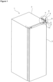
Figure 1 - is the perspective view of an embodiment of a cooling device. -
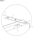
Figure 2 - is the view of the detail A ofFigure 1 . -
Figure 3 - is the detailed view of the cooling device when the door is locked. -
Figure 4 - is the top view of the cooling device in another embodiment of the present invention. -
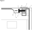
Figure 5 - is the view of the cross-section B-B inFigure 4 . -
Figure 6 - is the detailed cross-sectional view of the cooling device when the door is free. -
Figure 7 - is the detailed view of the cooling device when the door is free in another embodiment of the present invention. -
Figure 8 - is the perspective detailed view of the cooling device when the door is free in another embodiment of the present invention. -
Figure 9 - is the detailed view of the cooling device when the door is locked in another embodiment of the present invention. -
Figure 10 - is the perspective detailed view of the cooling device when the door is locked in another embodiment of the present invention. -
Figure 11 - is the detailed cross-sectional view of the cooling device when the door is locked in another embodiment of the present invention. - The elements illustrated in the figures are numbered as follows:
- 1.
- Cooling device
- 2.
- Body
- 3.
- Door
- 4.
- Hinge body
- 5.
- Hinge pin
- 6.
- Hinge pin housing
- 7.
- Bearing
- 8.
- Locking pin
- 9.
- Locking pin head
- 10.
- Locking pin shaft
- 11.
- Locking housing
- 12.
- Casing
- 13.
- Intermediate member
- 14.
- Lid
- 15.
- Arm
- 16.
- First section
- 17.
- Second section
- The cooling device (1) of the present invention comprises a body (2); at least one door (3); at least one hinge body (4) which is fixed to the body (2) at one end and to the door (3) at the other end; a hinge pin (5) which fixes the hinge body (4) to the door (3) and around which the door (3) rotates; a hinge pin housing (6) wherein the hinge pin (5) is seated; a bearing (7) which is arranged on the door (3) or the hinge pin (5); and a locking pin (8) which enters said bearing (7) and which prevents the door (3) from rotating so as to enable the same to remain closed.
- The hinge body (4) is fixed on the body (2) at one end by means of fixing members. The hinge pin (5) located at the other end of the hinge body (4) is seated into the hinge pin housing (6) on the door (3) and attached to the body (2) such that the door (3) rotates on the hinge pin (5). In the embodiment of the present invention, when the cooling device (1) is to be transported, the locking pin (8) is placed into the bearing (7) on the door (3) or the hinge pin (5). Thus, the door (3) is prevented from rotating on the hinge pin (5) so as to ensure that the door (3) remains closed on the body (2). When the transportation process is finished, the locking pin (8) is pulled out of the bearing (7) such that the hinge pin (5) and hence the door (3) are released and the door (3) can be opened/closed whenever desired.
- The locking pin (8) has a head (9) and a preferably cylindrical shaft (10) extending vertically from said head (9).
- In an embodiment of the present invention, the cooling device (1) comprises a locking housing (11) which is arranged on the end of the hinge body (4) extending towards the door (3) and wherein the locking pin (8) is inserted. In this embodiment, the bearing (7) is arranged on the door (3) and overlaps with the locking housing (11) and is on the same vertical axis with the latter. In this embodiment of the present invention, when the door (3) of the cooling device (1) is wanted to be locked, the locking pin (8) is inserted into the bearing (7) via the locking housing (11). In this case, while the locking pin head (9) remains on the hinge body (4), the locking pin shaft (10) passes through the locking housing (11) to be seated in the bearing (7), and the hinge body (4) remains between the locking pin head (9) and the bearing (7). Thus, the door (3) is prevented from rotating on the hinge pin (5) (
Figure 1 ,Figure 2 andFigure 3 ). - In another embodiment of the present invention, the cooling device (1) comprises a casing (12) on the door (3) or the body (2) wherein the locking pin (8) is stored. When the door (3) is wanted to be locked, the locking pin (8) taken out of the casing (12) is used, and the locking (8) is placed back into the casing (12) after the locking process is completed. In the preferred embodiment of the present invention, the casing (12) is located on the door (3), close to the hinge pin (5). In the embodiment of the present invention, the cooling device (1) comprises, on the casing (12), a first part (16) wherein the locking pin head (9) is seated, and a second part (17) wherein the locking pin shaft (10) is seated. Thus, the structure of the casing (12) is adapted to the structure of the locking pin (8).
- In another embodiment of the present invention, the cooling device (1) comprises a bearing (7) which is arranged on the hinge pin (5), which extends perpendicular to the rotation axis of the hinge pin (5) and which is wide enough to receive the locking pin (8). In this embodiment of the present invention, when the door (3) is wanted to be locked, the locking pin (8) is inserted into the bearing (7) perpendicular to the axis of rotation of the hinge pin (5), along the width of the hinge pin (5), which sits vertically in the hinge pin housing (6). In this case, the locking pin shaft (10) and the hinge pin (5) are perpendicular to each other. Thus, the door (3) is prevented from rotating on the hinge pin (5) so as to ensure that the door (3) is locked and remains closed. Upon being taken out of the bearing (7), the locking pin (8) shifts to the free position where the same can be opened and closed.
- In another version of this embodiment, the casing (12) and the hinge pin housing (6) are adjacent to each other and are connected to each other. In this embodiment of the present invention, the hinge pin housing (6) and the casing (12) are perpendicular to each other. In this case, the hinge pin (5) fits vertically into the hinge pin housing (6), while the locking pin (8) is placed in the casing (12) extending in the horizontal direction. In this embodiment of the present invention, the locking pin (8) in the casing (12) is slid, and the locking pin (8) engages with the bearing (7) extending on the hinge pin (5) in the same direction as the locking pin (8). In this case, the hinge pin (5) is prevented from rotating, thus preventing the door (3) from rotating and opening and keeping the same closed. When the locking pin (8) is slid in the opposite direction, the locking pin shaft (10) leaves the bearing (7) and is seated in the casing (12). Separation of the locking pin (8) from the bearing (7) enables the hinge pin (5) to rotate, and hence enables the door (3) connected to the hinge pin (5) to be opened and closed by shifting to the free position (
Figure 4 ,Figure 5 andFigure 6 ). - In another embodiment of the present invention, the cooling device (1) comprises an intermediate member (13), which forms the locking pin head (9) and which moves back and forth on the hinge body (4), in the horizontal plane, between the door (3) and the body (2). In this embodiment of the present invention, the cooling device (1) comprises a locking housing (11) which is arranged at the end of the hinge body (4) extending towards the body (3) and wherein the locking pin (8) is inserted, and a bearing (7) which is arranged on the door (3) and which overlaps with the locking housing (11). In this embodiment, when the door (3) is wanted to be locked, the intermediate member (13) with the locking pin (8) thereon is slid from the body (2) towards the door (3). As a result of this movement, the locking pin (8) is seated into the bearing (7) via the locking housing (11). In this case, the intermediate member (13) to which the locking pin (8) is connected remains on the hinge body (4), while the locking pin shaft (10) passes through the locking housing (11) to be seated into the bearing (7). In this embodiment of the present invention, the hinge body (4) remains between the intermediate member (13) and the bearing (7) in the locked position of the door (3). Thus, the door (3) is prevented from rotating on the hinge pin (5) (
Figure 8 ,Figure 10 andFigure 11 ). - In this embodiment of the present invention, the cooling device (1) comprises a lid (14) which covers the hinge body (4), the hinge pin (5) and the locking pin (8) and which protects said components from external factors, and an arm (15) which provides access to the intermediate member (13) via the lid (14) so as to enable the intermediate member (13), hence the locking pin (8), to be moved (
Figure 7 andFigure 9 ). - By means of the present invention, the door (3) of the cooling device (1) is kept locked during the transportation process, thus preventing the items such as shelves and storage containers in the cooling device (1) from falling and being damaged and preventing the door (3) from opening unintentionally and being deformed during the transportation process.
Claims (10)
- A cooling device (1) comprising a body (2); at least one door (3); at least one hinge body (4) which is fixed to the body (2) at one end and to the door (3) at the other end; a hinge pin (5) which fixes the hinge body (4) to the door (3) and around which the door (3) rotates; and a hinge pin housing (6) wherein the hinge pin (5) is seated; characterized by a bearing (7) which is arranged on the door (3) or the hinge pin (5); and a locking pin (8) which enters said bearing (7) and which prevents the door (3) from rotating so as to enable the same to remain closed.
- A cooling device (1) as in Claim 1, characterized by the locking pin (8) which has a head (9) and a preferably cylindrical shaft (10) extending vertically from said head (9).
- A cooling device (1) as in Claim 1 or Claim 2, characterized by a locking housing (11) which is arranged at the end of the hinge body (4) extending towards the body (3) and wherein the locking pin (8) is inserted.
- A cooling device (1) as in Claim 3, characterized by the bearing (7) which is arranged on the door (3), which overlaps with the locking housing (11) and which is on the same vertical axis with the latter.
- A cooling device (1) as in any one of the above claims, characterized by a casing (12) on the door (3) or the body (2) wherein the locking pin (8) is stored.
- A cooling device (1) as in Claim 5, characterized by a first part (16) wherein the locking pin head (9) is seated, and a second part (17) wherein the locking pin shaft (10) is seated, which are both arranged on the casing (12).
- A cooling device (1) as in Claim 5 or Claim 6, characterized by the casing (12) and the hinge pin housing (6) which are adjacent to each other and are connected to each other.
- A cooling device (1) as in Claim 2, characterized by an intermediate member (13), which forms the locking pin head (9) and which moves back and forth on the hinge body (4), in the horizontal plane, between the door (3) and the body (2).
- A cooling device (1) as in any one of the above claims, characterized by a lid (14) which covers the hinge body (4), the hinge pin (5) and the locking pin (8) and which protects said components from external factors
- A cooling device (1) as in Claim 9, characterized by an arm (15) which provides access to the intermediate member (13) via the lid (14) so as to enable the intermediate member (13), hence the locking pin (8), to be moved.
Applications Claiming Priority (1)
| Application Number | Priority Date | Filing Date | Title |
|---|---|---|---|
| TR202121161 | 2021-12-27 |
Publications (1)
| Publication Number | Publication Date |
|---|---|
| EP4202326A1 true EP4202326A1 (en) | 2023-06-28 |
Family
ID=84044337
Family Applications (1)
| Application Number | Title | Priority Date | Filing Date |
|---|---|---|---|
| EP22204765.6A Withdrawn EP4202326A1 (en) | 2021-12-27 | 2022-10-31 | A cooling device |
Country Status (1)
| Country | Link |
|---|---|
| EP (1) | EP4202326A1 (en) |
Citations (5)
| Publication number | Priority date | Publication date | Assignee | Title |
|---|---|---|---|---|
| JPS4810060U (en) * | 1971-06-16 | 1973-02-03 | ||
| JPS53108661U (en) * | 1977-02-07 | 1978-08-31 | ||
| JP2006308281A (en) | 2004-12-17 | 2006-11-09 | Matsushita Electric Ind Co Ltd | refrigerator |
| JP2013061085A (en) | 2011-09-12 | 2013-04-04 | Hitachi Appliances Inc | refrigerator |
| WO2015144247A1 (en) | 2014-03-28 | 2015-10-01 | Arcelik Anonim Sirketi | Improved handle assembly for refrigeration appliance door |
-
2022
- 2022-10-31 EP EP22204765.6A patent/EP4202326A1/en not_active Withdrawn
Patent Citations (5)
| Publication number | Priority date | Publication date | Assignee | Title |
|---|---|---|---|---|
| JPS4810060U (en) * | 1971-06-16 | 1973-02-03 | ||
| JPS53108661U (en) * | 1977-02-07 | 1978-08-31 | ||
| JP2006308281A (en) | 2004-12-17 | 2006-11-09 | Matsushita Electric Ind Co Ltd | refrigerator |
| JP2013061085A (en) | 2011-09-12 | 2013-04-04 | Hitachi Appliances Inc | refrigerator |
| WO2015144247A1 (en) | 2014-03-28 | 2015-10-01 | Arcelik Anonim Sirketi | Improved handle assembly for refrigeration appliance door |
Similar Documents
| Publication | Publication Date | Title |
|---|---|---|
| KR100662405B1 (en) | Drawer | |
| EP3807167B1 (en) | Group lock box with recessed door to create a slim profile | |
| US8215728B2 (en) | Storage enclosure | |
| EP0311242A1 (en) | Curtainside truck trailer closure assembly | |
| US11161686B2 (en) | Collapsible intermodal container and a collapsible intermodal container assembly | |
| US7114356B1 (en) | Padlock that can control operation of locking hook | |
| KR101040720B1 (en) | Open top container | |
| KR100845087B1 (en) | Marine Container | |
| WO2017087618A1 (en) | Intermittent locking door mechanism | |
| TR2021021161A2 (en) | A COOLER | |
| WO1994029175A1 (en) | Container with door comprising hinged section and sliding shutter | |
| JP2009500050A (en) | Module adapter | |
| JP3005585B1 (en) | Cartridge library device | |
| US20040007615A1 (en) | Cashbox and apparatus for emptying the cashbox | |
| JPH11196943A (en) | Sliding hinge mechanism and storage tool using the same | |
| JP3336156B2 (en) | Basket rotating device in surface treatment equipment | |
| KR102364216B1 (en) | Safety cabinet for dangerous material | |
| KR20260030272A (en) | The ventilation system with efficient locking structure for ships | |
| KR0139952B1 (en) | Automotive Glove Box with Table | |
| JP4305919B2 (en) | game machine | |
| JPH09293975A (en) | Equipment storage box | |
| KR200371677Y1 (en) | A rail separation preventive guide bar of slide a rail | |
| KR200152339Y1 (en) | A tool case of a look system | |
| JPH08129672A (en) | vending machine | |
| JP6960669B2 (en) | Fixing device for pallet lid and pallet lid |
Legal Events
| Date | Code | Title | Description |
|---|---|---|---|
| PUAI | Public reference made under article 153(3) epc to a published international application that has entered the european phase |
Free format text: ORIGINAL CODE: 0009012 |
|
| STAA | Information on the status of an ep patent application or granted ep patent |
Free format text: STATUS: REQUEST FOR EXAMINATION WAS MADE |
|
| 17P | Request for examination filed |
Effective date: 20221031 |
|
| AK | Designated contracting states |
Kind code of ref document: A1 Designated state(s): AL AT BE BG CH CY CZ DE DK EE ES FI FR GB GR HR HU IE IS IT LI LT LU LV MC ME MK MT NL NO PL PT RO RS SE SI SK SM TR |
|
| STAA | Information on the status of an ep patent application or granted ep patent |
Free format text: STATUS: THE APPLICATION IS DEEMED TO BE WITHDRAWN |
|
| 18D | Application deemed to be withdrawn |
Effective date: 20240103 |