EP4202255A1 - Air spring for vehicle and vehicle - Google Patents
Air spring for vehicle and vehicle Download PDFInfo
- Publication number
- EP4202255A1 EP4202255A1 EP22214634.2A EP22214634A EP4202255A1 EP 4202255 A1 EP4202255 A1 EP 4202255A1 EP 22214634 A EP22214634 A EP 22214634A EP 4202255 A1 EP4202255 A1 EP 4202255A1
- Authority
- EP
- European Patent Office
- Prior art keywords
- inner core
- breathing hole
- air spring
- dust
- air
- Prior art date
- Legal status (The legal status is an assumption and is not a legal conclusion. Google has not performed a legal analysis and makes no representation as to the accuracy of the status listed.)
- Granted
Links
Images


Classifications
-
- F—MECHANICAL ENGINEERING; LIGHTING; HEATING; WEAPONS; BLASTING
- F16—ENGINEERING ELEMENTS AND UNITS; GENERAL MEASURES FOR PRODUCING AND MAINTAINING EFFECTIVE FUNCTIONING OF MACHINES OR INSTALLATIONS; THERMAL INSULATION IN GENERAL
- F16F—SPRINGS; SHOCK-ABSORBERS; MEANS FOR DAMPING VIBRATION
- F16F9/00—Springs, vibration-dampers, shock-absorbers, or similarly-constructed movement-dampers using a fluid or the equivalent as damping medium
- F16F9/02—Springs, vibration-dampers, shock-absorbers, or similarly-constructed movement-dampers using a fluid or the equivalent as damping medium using gas only or vacuum
-
- B—PERFORMING OPERATIONS; TRANSPORTING
- B60—VEHICLES IN GENERAL
- B60G—VEHICLE SUSPENSION ARRANGEMENTS
- B60G11/00—Resilient suspensions characterised by arrangement, location or kind of springs
- B60G11/26—Resilient suspensions characterised by arrangement, location or kind of springs having fluid springs only, e.g. hydropneumatic springs
- B60G11/27—Resilient suspensions characterised by arrangement, location or kind of springs having fluid springs only, e.g. hydropneumatic springs wherein the fluid is a gas
-
- F—MECHANICAL ENGINEERING; LIGHTING; HEATING; WEAPONS; BLASTING
- F16—ENGINEERING ELEMENTS AND UNITS; GENERAL MEASURES FOR PRODUCING AND MAINTAINING EFFECTIVE FUNCTIONING OF MACHINES OR INSTALLATIONS; THERMAL INSULATION IN GENERAL
- F16F—SPRINGS; SHOCK-ABSORBERS; MEANS FOR DAMPING VIBRATION
- F16F9/00—Springs, vibration-dampers, shock-absorbers, or similarly-constructed movement-dampers using a fluid or the equivalent as damping medium
- F16F9/32—Details
- F16F9/38—Covers for protection or appearance
-
- F—MECHANICAL ENGINEERING; LIGHTING; HEATING; WEAPONS; BLASTING
- F16—ENGINEERING ELEMENTS AND UNITS; GENERAL MEASURES FOR PRODUCING AND MAINTAINING EFFECTIVE FUNCTIONING OF MACHINES OR INSTALLATIONS; THERMAL INSULATION IN GENERAL
- F16F—SPRINGS; SHOCK-ABSORBERS; MEANS FOR DAMPING VIBRATION
- F16F9/00—Springs, vibration-dampers, shock-absorbers, or similarly-constructed movement-dampers using a fluid or the equivalent as damping medium
- F16F9/02—Springs, vibration-dampers, shock-absorbers, or similarly-constructed movement-dampers using a fluid or the equivalent as damping medium using gas only or vacuum
- F16F9/04—Springs, vibration-dampers, shock-absorbers, or similarly-constructed movement-dampers using a fluid or the equivalent as damping medium using gas only or vacuum in a chamber with a flexible wall
- F16F9/05—Springs, vibration-dampers, shock-absorbers, or similarly-constructed movement-dampers using a fluid or the equivalent as damping medium using gas only or vacuum in a chamber with a flexible wall the flexible wall being of the rolling diaphragm type
-
- B—PERFORMING OPERATIONS; TRANSPORTING
- B60—VEHICLES IN GENERAL
- B60G—VEHICLE SUSPENSION ARRANGEMENTS
- B60G2202/00—Indexing codes relating to the type of spring, damper or actuator
- B60G2202/10—Type of spring
- B60G2202/15—Fluid spring
- B60G2202/152—Pneumatic spring
-
- B—PERFORMING OPERATIONS; TRANSPORTING
- B60—VEHICLES IN GENERAL
- B60G—VEHICLE SUSPENSION ARRANGEMENTS
- B60G2206/00—Indexing codes related to the manufacturing of suspensions: constructional features, the materials used, procedures or tools
- B60G2206/01—Constructional features of suspension elements, e.g. arms, dampers, springs
- B60G2206/40—Constructional features of dampers and/or springs
- B60G2206/42—Springs
-
- B—PERFORMING OPERATIONS; TRANSPORTING
- B60—VEHICLES IN GENERAL
- B60G—VEHICLE SUSPENSION ARRANGEMENTS
- B60G2800/00—Indexing codes relating to the type of movement or to the condition of the vehicle and to the end result to be achieved by the control action
- B60G2800/16—Running
- B60G2800/162—Reducing road induced vibrations
Definitions
- the disclosure relates to an air spring for a vehicle and a vehicle.
- air springs have excellent elasticity, and can adjust the air pressure with the change of load, which greatly improves the comfort during driving of the vehicle. Meanwhile, the air spring can well isolate high-frequency vibrations, enhance ride comfort, reduce noises, and increase the service life of parts. Thereby, air springs are widely used in the field of vehicles.
- a venting structure of an existing air spring for a vehicle due to the principle and the structure thereof, is unable to filter the dust and sand in the air, thereby causing damage to or even failure of a rubber bladder in the air spring.
- a filter screen is provided at an air inlet to filter the dust and sand in the air.
- filtering the dust and sand in the air by providing the filter screen at the air inlet usually has the problems of a poor filtering effect and frequent replacement of a filter screen.
- the disclosure provides an air spring for a vehicle, the air spring comprising a dust-proof shade, an inner core and a bladder, wherein the inner core is in the shape of an upwardly open barrel, the dust-proof shade surrounds an outer side of a sidewall of the inner core, the dust-proof shade encloses a chamber with the sidewall of the inner core, and the bladder is arranged inside the chamber; and the sidewall of the inner core is provided with a first breathing hole and a second breathing hole, an inner side of the inner core is in communication with the outside through the first breathing hole, the inner side of the inner core is in communication with the chamber through the second breathing hole, and the first breathing hole and the second breathing hole are both arranged away from a bottom portion of the inner core.
- a protrusion is provided at a middle position of the bottom portion of the inner core, the protrusion forms a first platform, and the protrusion forms an annular cavity with the inner side of the sidewall of the inner core.
- a plurality of baffles are provided inside the annular cavity, and the baffles abut against an inner ring and an outer ring of the annular cavity respectively on two radial sides of the annular cavity to form a plurality of sand accommodating chambers.
- an outer sidewall of each of the sand accommodating chambers is provided with the first breathing hole and the second breathing hole.
- the first breathing holes and the second breathing holes are alternately arranged on the outer sidewalls of two adjacent sand accommodating chambers.
- a bottom portion of the baffle is connected to the bottom portion of the inner core, and a top portion of the baffle is connected to a top portion of the inner core.
- the air spring further comprises a seal cover, a notch is provided at an opening of the inner core, the seal cover covers the opening of the inner core, and the notch and the seal cover together enclose the first breathing hole.
- the first breathing hole is further away from the bottom portion of the inner core than the second breathing hole.
- a protruded edge is provided on the outer side of the sidewall of the inner core, a groove is provided on the dust-proof shade, and the dust-proof shade is clamped on the protruded edge through the groove.
- the disclosure further provides a vehicle.
- the vehicle comprises an air spring for a vehicle according to any one of the foregoing technical solutions.
- an air spring comprises a dust-proof shade, an inner core and a bladder, wherein the inner core is in the shape of an upwardly open barrel, the dust-proof shade surrounds an outer side of a sidewall of the inner core, the dust-proof shade encloses a chamber with the sidewall of the inner core, and the bladder is arranged inside the chamber; and the sidewall of the inner core is provided with a first breathing hole and a second breathing hole, an inner side of the inner core is in communication with the outside through the first breathing hole, the inner side of the inner core is in communication with the chamber through the second breathing hole, and the first breathing hole and the second breathing hole are both arranged away from a bottom portion of the inner core.
- the inner core of the air spring for a vehicle is in the shape of an upwardly open barrel
- the dust-proof shade encloses the chamber with the sidewall of the inner core
- the sidewall of the inner core is further provided with the first breathing hole and the second breathing hole
- the inner side of the inner core is in communication with the outside through the first breathing hole
- the inner side of the inner core is in communication with the chamber through the second breathing hole
- the first breathing hole and the second breathing hole are both arranged away from the bottom portion of the inner core, such that air enters the inner side of the inner core through the first breathing hole and can flow out from the inner side of the inner core through the second breathing hole and flow into the chamber enclosed by the dust-proof shade and the inner core.
- the air firstly enters the inner side of the inner core, at this time, the dust and sand in the air falls on the bottom portion of the inner side of the inner core under the action of its own gravity, and then the air further enters the chamber through the second breathing hole, such that the dust and sand in the air is filtered, and the dust and sand is prevented from entering the chamber together with the air, thereby protecting the bladder arranged in the chamber from being damaged, and increasing the service life of the air spring.
- the air spring for a vehicle improves a filtering effect on the dust and sand in the air, and also solves the problem of frequent replacement of a filter screen.
- first breathing hole being a square hole and a second breathing hole being a circular hole are taken as examples to describe the shapes of the first breathing hole and the second breathing hole
- the shapes of the first breathing hole and the second breathing hole are not limited to this, as long as the first breathing hole and the second breathing hole may satisfy that the air can enter an inner side of an inner core through the first breathing hole and flow out from the inner side of the inner core through the second breathing hole, and can flow into a chamber.
- the shape of the first breathing hole may also be a ring, a trapezoid, a triangle, etc.
- the shape of the second breathing hole may also be a square, a trapezoid, a triangle, etc.
- connection should be interpreted in a broad sense unless explicitly defined and limited otherwise, which, for example, may mean a fixed connection, a detachable connection or an integral connection; may be a direct connection, or an indirect connection through an intermediate medium.
- connect should be interpreted in a broad sense unless explicitly defined and limited otherwise, which, for example, may mean a fixed connection, a detachable connection or an integral connection; may be a direct connection, or an indirect connection through an intermediate medium.
- a venting structure of the air spring itself is unable to filter the dust and sand in the air.
- the dust and sand in the air entering the air spring needs to be filtered to avoid direct contact of the dust and sand in the air with a bladder in the air spring, thereby protecting the bladder and increasing the service life of the air spring. Therefore, usually a filter screen is provided at an air inlet to filter the dust and sand in the air.
- filtering the dust and sand in the air by providing the filter screen at the air inlet usually has the problems of a poor filtering effect and frequent replacement of a filter screen.
- the disclosure provides a new air spring for a vehicle and a vehicle.
- an air spring for a vehicle comprises a dust-proof shade 1, an inner core 2 and a bladder 3, wherein the inner core 2 is in the shape of an upwardly open barrel, the dust-proof shade 1 surrounds an outer side of a sidewall 21 of the inner core 2, the dust-proof shade 1 encloses a chamber 11 with the sidewall 21 of the inner core 2, and the bladder 3 is arranged inside the chamber 11; and the sidewall 21 of the inner core 2 is provided with a first breathing hole 211 and a second breathing hole 212, an inner side of the inner core 2 is in communication with the outside through the first breathing hole 211, the inner side of the inner core 2 is in communication with the chamber 11 through the second breathing hole 212, and the first breathing hole 211 and the second breathing hole 212 are both arranged away from a bottom portion 22 of the inner core 2.
- the inner core 2 of the air spring for a vehicle is in the shape of an upwardly open barrel
- the dust-proof shade 1 encloses the chamber 11 with the sidewall 21 of the inner core 2
- the sidewall 21 of the inner core 2 is further provided with the first breathing hole 211 and the second breathing hole 212
- the inner side of the inner core 2 is in communication with the outside through the first breathing hole 211
- the inner side of the inner core 2 is in communication with the chamber 11 through the second breathing hole 212
- the first breathing hole 211 and the second breathing hole 212 are both arranged away from the bottom portion 22 of the inner core 2, such that air enters the inner side of the inner core 2 through the first breathing hole 211 and can flow out from the inner side of the inner core 2 through the second breathing hole 212 and flow into the chamber 11 enclosed by the dust-proof shade 1 and the inner core 2, and a flow path of the air is in a direction shown by an arrow in Fig.
- the air spring for a vehicle improves a filtering effect on the dust and sand in the air, and also solves the problem of frequent replacement of a filter screen.
- the first breathing hole 211 is a square hole
- the second breathing hole 212 is a circular hole.
- first breathing hole 211 being a square hole and the second breathing hole 212 being a circular hole are taken as examples to describe the shapes of the first breathing hole 211 and the second breathing hole 212
- the shapes of the first breathing hole 211 and the second breathing hole 212 are not limited to this, as long as the first breathing hole 211 and the second breathing hole 212 may satisfy that the air can enter the inner side of the inner core 2 through the first breathing hole 211 and flow out from the inner side of the inner core 2 through the second breathing hole 212, and can flow into the chamber 11.
- the shape of the first breathing hole 211 may also be a ring, a trapezoid, a triangle, etc.
- the shape of the second breathing hole 212 may also be a square, a trapezoid, a triangle, etc.
- a protrusion 221 is provided at a middle position of the bottom portion 22 of the inner core 2, the protrusion 221 forms a first platform 2211, and the protrusion 221 forms an annular cavity 213 with the inner side of the sidewall 21 of the inner core 2.
- the protrusion 221 is provided at the middle position of the bottom portion 22 of the inner core 2, the protrusion 221 forms the first platform 2211, and the protrusion 221 forms the annular cavity 213 with the outer side of the sidewall 21 of the inner core 2, such that the air firstly enters the inner side of the annular cavity 213 through the first breathing hole 211.
- the dust and sand in the air falls on the bottom portion of the annular cavity 213 under the action of its own gravity, such that the dust and sand in the air is filtered, and then the filtered air further enters the chamber 11 through the second breathing hole 212, such that the dust and sand is prevented from entering the chamber 11 together with the air, thereby protecting the bladder 3 arranged in the chamber 11 from being damaged, and increasing the service life of the air spring.
- the annular cavity 213 in this embodiment can also play a better role in collecting the dust and sand in the air.
- the protrusion 221 is provided at the middle position of the bottom portion 22 of the inner core 2, to also enhance the structural strength of the inner core 2, thereby increasing the overall structural strength of the air spring and improving the durability of the air spring.
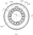
- a plurality of baffles 2131 are provided inside the annular cavity 213, and the baffles 2131 abut against an inner ring 2132 and an outer ring 2133 of the annular cavity 213 respectively on two radial sides of the annular cavity 213 to form a plurality of sand accommodating chambers 2134 (the sand accommodating chamber 2134 is an area shown as a dashed box in Fig. 1 and Fig. 3 ).
- An outer sidewall of each sand accommodating chamber 2134 is provided with the first breathing hole 211 and the second breathing hole 212.
- the air firstly enters the sand accommodating chamber 2134 through the first breathing hole 211 provided on the outer sidewall of the sand accommodating chamber 2134, the dust and sand in the air falls on a bottom portion of the sand accommodating chamber 2134 under the action of its own gravity, and then the filtered air further flows out from the sand accommodating chamber 2134 through the second breathing hole 212 provided on the sand accommodating chamber 2134 and flows into the chamber 11, such that the dust and sand is prevented from entering the chamber 11 together with the air.
- the plurality of baffles 2131 are provided in the annular cavity 213 to form the plurality of sand accommodating chambers 2134, and the outer sidewall of each sand accommodating chamber 2134 is provided with the first breathing hole 211 and the second breathing hole 212, so as to filter multiple airflows at the same time, reduce the interference between the airflows, and prevent one airflow from blowing up grit deposited in another chamber, thereby improving the filtering effect and filtering efficiency on the air.
- the first breathing holes 211 and the second breathing holes 212 are alternately arranged on the outer sidewalls of two adjacent sand accommodating chambers 2134.
- the first breathing holes 211 and the second breathing holes 212 are alternately arranged on the outer sidewalls of two adjacent sand accommodating chambers 2134, such that the air firstly enters the sand accommodating chamber 2134 through the first breathing hole 211 provided on the outer sidewall of the sand accommodating chamber 2134, the dust and sand in the air falls on the bottom portion of the sand accommodating chamber 2134 under the action of its own gravity, and then the air needs to pass through a gap between the baffle 2131 and a top portion 24 of the inner core 2, bypass the baffle 2131, and enter the chamber 11 through the second breathing hole 212 provided on the outer sidewall of the adjacent sand accommodating chamber 2134.
- the grit in the above air flow process, if the grit tends to follow the air to enter the second breathing hole 212, the grit must be at least blown up to a height higher than one baffle 2131, which increases the flow path of the air in the annular cavity 213, and improves the filtering effect on the air.
- the baffle 2131 has a strong blocking effect on the dust and sand in the air, so as to block the dust and sand in the air from entering the chamber 11, and to further improve the filtering effect on the air.
- the first breathing hole 211 is further away from the bottom portion 22 of the inner core 2 than the second breathing hole 212.
- relative positions of the first breathing hole 211 and the second breathing hole 212 are configured such that the first breathing hole 211 is further away from the bottom portion 22 of the inner core 2 than the second breathing hole 212, to achieve a certain height difference between the first breathing hole 211 and the second breathing hole 212 along an axial direction of the inner core 2 in the shape of an upwardly open barrel (that is, along the axial direction of the inner core 2 in the shape of an upwardly open barrel, the first breathing hole 211 is located above the second breathing hole 212), so that during the process in which the air enters the inner side of the inner core 2 through the first breathing hole 211, and flows out from the inner side of the inner core 2 through the second breathing hole 212 and enters the chamber 11, the air can flow through the above flow path more smoothly.
- a bottom portion of the baffle 2131 is connected to the bottom portion 22 of the inner core 2, and a top portion of the baffle 2131 is connected to the top portion 24 of the inner core 2.
- the baffle 2131 is arranged such that the bottom portion of the baffle 2131 is connected to the bottom portion 22 of the inner core 2, and the top portion of the baffle 2131 is connected to the top portion 24 of the inner core 2, so as to increase the structural strength of the inner core 2, thereby increasing the overall structural strength of the air spring, and improving the durability of the air spring.
- the air spring further comprises a seal cover (not shown in the figure), a notch 23 is provided at an opening of the inner core 2, the seal cover covers the opening of the inner core 2, and the notch 23 and the seal cover together enclose the first breathing hole 211.
- the notch 23 is provided at the opening of the inner core 2, and the seal cover covers the opening of the inner core 2, such that the notch 23 and the seal cover together enclose the first breathing hole 211, which can provide a necessary air inlet for the air to enter the inner side of the inner core 2, and can also facilitate the assembly of the air spring to a vehicle body.
- a protruded edge 214 is provided on the outer side of the sidewall 21 of the inner core 2, the dust-proof shade 1 is provided with a groove 12, and the dust-proof shade 1 is clamped on the protruded edge 214 through the groove 12.
- the protruded edge 214 is provided on the outer side of the sidewall 21 of the inner core 2, the groove 12 is provided on the dust-proof shade 1, and the dust-proof shade 1 is clamped to the protruded edge 214 through the groove 12, which makes it easy to assembly the dust-proof shade 1 with the inner core 2.
- the inner core 2 of the air spring for a vehicle is in the shape of an upwardly open barrel
- the dust-proof shade 1 encloses the chamber 11 with the sidewall 21 of the inner core 2
- the sidewall 21 of the inner core 2 is further provided with the first breathing hole 211 and the second breathing hole 212
- the inner side of the inner core 2 is in communication with the outside through the first breathing hole 211
- the inner side of the inner core 2 is in communication with the chamber 11 through the second breathing hole 212
- the first breathing hole 211 and the second breathing hole 212 are both arranged away from the bottom portion 22 of the inner core 2, such that the air enters the inner side of the inner core 2 through the first breathing hole 211 and can flow out from the inner side of the inner core 2 through the second breathing hole 212 and flow into the chamber 11 enclosed by the dust-proof shade 1 and the inner core 2.
- the air firstly enters the inner side of the inner core 2, at this time, the dust and sand in the air falls on the bottom portion of the inner side of the inner core 2 under the action of its own gravity, and then the filtered air further enters the chamber 11 through the second breathing hole 212, such that the dust and sand in the air is filtered, and the dust and sand is prevented from entering the chamber 11 together with the air, thereby protecting the bladder 3 arranged in the chamber 11 from being damaged, and increasing the service life of the air spring.
- the air spring for a vehicle improves a filtering effect on the dust and sand in the air, and also solves the problem of frequent replacement of a filter screen.
- the protrusion 221 is provided at the middle position of the bottom portion 22 of the inner core 2, the protrusion 221 forms the first platform 2211, the protrusion 221 forms the annular cavity 213 with the outer side of the sidewall 21 of the inner core 2, and the annular cavity 213 in this embodiment can better collect the dust and sand in the air.
- the protrusion 221 is provided at the middle position of the bottom portion 22 of the inner core 2, to also enhance the structural strength of the inner core 2, thereby increasing the overall structural strength of the air spring and improving the durability of the air spring.
- the plurality of baffles 2131 are provided inside the annular cavity 213, and the baffles 2131 abut against the inner ring 2132 and the outer ring 2133 of the annular cavity 213 respectively on two radial sides of the annular cavity 213 to form the plurality of sand accommodating chambers 2134.
- the first breathing hole 211 and the second breathing hole 212 are arranged in different configurations on the outer sidewall of the sand accommodating chamber 2134, so as to filter multiple airflows at the same time, reduce the interference between the airflows, and prevent one airflow from blowing up the grit deposited in another chamber, thereby improving the filtering efficiency and the filtering effect on the air.
- the disclosure further provides a vehicle.
- the vehicle is provided with an air spring for a vehicle according to any one of the foregoing implementations.
Landscapes
- Engineering & Computer Science (AREA)
- General Engineering & Computer Science (AREA)
- Mechanical Engineering (AREA)
- Fluid-Damping Devices (AREA)
Abstract
Description
- The disclosure relates to an air spring for a vehicle and a vehicle.
- With the rapid development of the vehicle industry, consumers have higher and higher requirements for vehicle performance. Compared with metal springs, air springs have excellent elasticity, and can adjust the air pressure with the change of load, which greatly improves the comfort during driving of the vehicle. Meanwhile, the air spring can well isolate high-frequency vibrations, enhance ride comfort, reduce noises, and increase the service life of parts. Thereby, air springs are widely used in the field of vehicles. A venting structure of an existing air spring for a vehicle, due to the principle and the structure thereof, is unable to filter the dust and sand in the air, thereby causing damage to or even failure of a rubber bladder in the air spring.
- In order to solve the above-mentioned problems, in the existing air spring for a vehicle, usually a filter screen is provided at an air inlet to filter the dust and sand in the air.
- However, in the existing air spring for a vehicle, filtering the dust and sand in the air by providing the filter screen at the air inlet usually has the problems of a poor filtering effect and frequent replacement of a filter screen.
- Accordingly, there is a need in the art for a new air spring for a vehicle and a vehicle to solve the above problems.
- In order to solve the problems in the prior art, the disclosure provides an air spring for a vehicle, the air spring comprising a dust-proof shade, an inner core and a bladder, wherein the inner core is in the shape of an upwardly open barrel, the dust-proof shade surrounds an outer side of a sidewall of the inner core, the dust-proof shade encloses a chamber with the sidewall of the inner core, and the bladder is arranged inside the chamber; and the sidewall of the inner core is provided with a first breathing hole and a second breathing hole, an inner side of the inner core is in communication with the outside through the first breathing hole, the inner side of the inner core is in communication with the chamber through the second breathing hole, and the first breathing hole and the second breathing hole are both arranged away from a bottom portion of the inner core.
- In the above preferred technical solution of the air spring for a vehicle, a protrusion is provided at a middle position of the bottom portion of the inner core, the protrusion forms a first platform, and the protrusion forms an annular cavity with the inner side of the sidewall of the inner core.
- In the above preferred technical solution of the air spring for a vehicle, a plurality of baffles are provided inside the annular cavity, and the baffles abut against an inner ring and an outer ring of the annular cavity respectively on two radial sides of the annular cavity to form a plurality of sand accommodating chambers.
- In the above preferred technical solution of the air spring for a vehicle, an outer sidewall of each of the sand accommodating chambers is provided with the first breathing hole and the second breathing hole.
- In the above preferred technical solution of the air spring for a vehicle, the first breathing holes and the second breathing holes are alternately arranged on the outer sidewalls of two adjacent sand accommodating chambers.
- In the above preferred technical solution of the air spring for a vehicle, a bottom portion of the baffle is connected to the bottom portion of the inner core, and a top portion of the baffle is connected to a top portion of the inner core.
- In the above preferred technical solution of the air spring for a vehicle, the air spring further comprises a seal cover, a notch is provided at an opening of the inner core, the seal cover covers the opening of the inner core, and the notch and the seal cover together enclose the first breathing hole.
- In the above preferred technical solution of the air spring for a vehicle, the first breathing hole is further away from the bottom portion of the inner core than the second breathing hole.
- In the above preferred technical solution of the air spring for a vehicle, a protruded edge is provided on the outer side of the sidewall of the inner core, a groove is provided on the dust-proof shade, and the dust-proof shade is clamped on the protruded edge through the groove.
- The disclosure further provides a vehicle. The vehicle comprises an air spring for a vehicle according to any one of the foregoing technical solutions.
- It can be understood by those skilled in the art that in the technical solution of the disclosure, an air spring comprises a dust-proof shade, an inner core and a bladder, wherein the inner core is in the shape of an upwardly open barrel, the dust-proof shade surrounds an outer side of a sidewall of the inner core, the dust-proof shade encloses a chamber with the sidewall of the inner core, and the bladder is arranged inside the chamber; and the sidewall of the inner core is provided with a first breathing hole and a second breathing hole, an inner side of the inner core is in communication with the outside through the first breathing hole, the inner side of the inner core is in communication with the chamber through the second breathing hole, and the first breathing hole and the second breathing hole are both arranged away from a bottom portion of the inner core.
- In the above configuration, the inner core of the air spring for a vehicle according to the disclosure is in the shape of an upwardly open barrel, the dust-proof shade encloses the chamber with the sidewall of the inner core, the sidewall of the inner core is further provided with the first breathing hole and the second breathing hole, the inner side of the inner core is in communication with the outside through the first breathing hole, the inner side of the inner core is in communication with the chamber through the second breathing hole, and the first breathing hole and the second breathing hole are both arranged away from the bottom portion of the inner core, such that air enters the inner side of the inner core through the first breathing hole and can flow out from the inner side of the inner core through the second breathing hole and flow into the chamber enclosed by the dust-proof shade and the inner core. In the above air flow process, the air firstly enters the inner side of the inner core, at this time, the dust and sand in the air falls on the bottom portion of the inner side of the inner core under the action of its own gravity, and then the air further enters the chamber through the second breathing hole, such that the dust and sand in the air is filtered, and the dust and sand is prevented from entering the chamber together with the air, thereby protecting the bladder arranged in the chamber from being damaged, and increasing the service life of the air spring. In addition, compared with an existing air spring for a vehicle, the air spring for a vehicle according to the disclosure improves a filtering effect on the dust and sand in the air, and also solves the problem of frequent replacement of a filter screen.
- An air spring for a vehicle and a vehicle according to the disclosure are described below with reference to the drawings. In the accompanying drawings:
-
Fig. 1 is a top view of an air spring for a vehicle; -
Fig. 2 is a sectional view at A-A of the air spring for a vehicle; and -
Fig. 3 is a sectional view at B-B of the air spring for a vehicle. -
- 1- Dust-proof shade; 11- Chamber; 12 - Groove;
- 2- Inner core; 21- Sidewall; 211- First breathing hole; 212- Second breathing hole; 213- Annular cavity; 2131- Baffle; 2132- Inner ring; 2133- Outer ring; 2134- Sand accommodating chamber; 214- Protruded edge; 22- Bottom portion; 221-Protrusion; 2211- First platform; 23 - Notch; 24- Top portion;
- 3- Bladder.
- Preferred implementations of the disclosure are described below with reference to the accompanying drawings. Those skilled in the art should understand that these implementations are only used to explain the technical principles of the disclosure, and are not intended to limit the scope of protection of the disclosure. Those skilled in the art can make adjustments according to requirements so as to adapt to specific application scenarios. For example, although a first breathing hole being a square hole and a second breathing hole being a circular hole are taken as examples to describe the shapes of the first breathing hole and the second breathing hole, in the disclosure, the shapes of the first breathing hole and the second breathing hole are not limited to this, as long as the first breathing hole and the second breathing hole may satisfy that the air can enter an inner side of an inner core through the first breathing hole and flow out from the inner side of the inner core through the second breathing hole, and can flow into a chamber. For example, the shape of the first breathing hole may also be a ring, a trapezoid, a triangle, etc., and the shape of the second breathing hole may also be a square, a trapezoid, a triangle, etc.
- It should be noted that, in the description of the disclosure, the terms that indicate the direction or positional relationship, such as "inner", and "outer", are based on the direction or positional relationship shown in the figures, which is merely for ease of description instead of indicating or implying that the device or element must have a particular orientation or be constructed and operated in a particular orientation, and therefore, should not be construed as limiting the disclosure. In addition, the terms "first" and "second" are used for descriptive purposes only, and cannot be understood as indicating or implying relative importance.
- In addition, it should also be noted that, in the description of the disclosure, the terms "connect" should be interpreted in a broad sense unless explicitly defined and limited otherwise, which, for example, may mean a fixed connection, a detachable connection or an integral connection; may be a direct connection, or an indirect connection through an intermediate medium. For a person skilled in the art, the specific meanings of the terms described above in the disclosure are capable of being interpreted according to the specific conditions.
- In an existing air spring for a vehicle, due to the principle and the structure thereof, a venting structure of the air spring itself is unable to filter the dust and sand in the air. The dust and sand in the air entering the air spring needs to be filtered to avoid direct contact of the dust and sand in the air with a bladder in the air spring, thereby protecting the bladder and increasing the service life of the air spring. Therefore, usually a filter screen is provided at an air inlet to filter the dust and sand in the air.
- However, filtering the dust and sand in the air by providing the filter screen at the air inlet usually has the problems of a poor filtering effect and frequent replacement of a filter screen.
- Thus, the disclosure provides a new air spring for a vehicle and a vehicle.
- Referring to
Figs. 1 and2 first, an air spring for a vehicle according to the disclosure is described. - As shown in
Figs. 1 and2 , an air spring for a vehicle according to the disclosure comprises a dust-proof shade 1, aninner core 2 and abladder 3, wherein theinner core 2 is in the shape of an upwardly open barrel, the dust-proof shade 1 surrounds an outer side of asidewall 21 of theinner core 2, the dust-proof shade 1 encloses achamber 11 with thesidewall 21 of theinner core 2, and thebladder 3 is arranged inside thechamber 11; and thesidewall 21 of theinner core 2 is provided with afirst breathing hole 211 and asecond breathing hole 212, an inner side of theinner core 2 is in communication with the outside through thefirst breathing hole 211, the inner side of theinner core 2 is in communication with thechamber 11 through thesecond breathing hole 212, and thefirst breathing hole 211 and thesecond breathing hole 212 are both arranged away from abottom portion 22 of theinner core 2. - In the above configuration, the
inner core 2 of the air spring for a vehicle according to the disclosure is in the shape of an upwardly open barrel, the dust-proof shade 1 encloses thechamber 11 with thesidewall 21 of theinner core 2, thesidewall 21 of theinner core 2 is further provided with thefirst breathing hole 211 and thesecond breathing hole 212, the inner side of theinner core 2 is in communication with the outside through thefirst breathing hole 211, the inner side of theinner core 2 is in communication with thechamber 11 through thesecond breathing hole 212, and thefirst breathing hole 211 and thesecond breathing hole 212 are both arranged away from thebottom portion 22 of theinner core 2, such that air enters the inner side of theinner core 2 through thefirst breathing hole 211 and can flow out from the inner side of theinner core 2 through thesecond breathing hole 212 and flow into thechamber 11 enclosed by the dust-proof shade 1 and theinner core 2, and a flow path of the air is in a direction shown by an arrow inFig. 2 . In the above air flow process, the air firstly enters the inner side of theinner core 2, at this time, the dust and sand in the air falls on the bottom portion of the inner side of theinner core 2 under the action of its own gravity, and then the filtered air further enters thechamber 11 through thesecond breathing hole 212, such that the dust and sand in the air is filtered, and the dust and sand is prevented from entering thechamber 11 together with the air, thereby protecting thebladder 3 arranged in thechamber 11 from being damaged, and increasing the service life of the air spring. In addition, compared with the existing air spring for a vehicle, the air spring for a vehicle according to the disclosure improves a filtering effect on the dust and sand in the air, and also solves the problem of frequent replacement of a filter screen. - In this embodiment, the
first breathing hole 211 is a square hole, and thesecond breathing hole 212 is a circular hole. - It can be understood that, although in this embodiment the
first breathing hole 211 being a square hole and thesecond breathing hole 212 being a circular hole are taken as examples to describe the shapes of thefirst breathing hole 211 and thesecond breathing hole 212, in this embodiment, the shapes of thefirst breathing hole 211 and thesecond breathing hole 212 are not limited to this, as long as thefirst breathing hole 211 and thesecond breathing hole 212 may satisfy that the air can enter the inner side of theinner core 2 through thefirst breathing hole 211 and flow out from the inner side of theinner core 2 through thesecond breathing hole 212, and can flow into thechamber 11. For example, the shape of thefirst breathing hole 211 may also be a ring, a trapezoid, a triangle, etc., and the shape of thesecond breathing hole 212 may also be a square, a trapezoid, a triangle, etc. - Further referring to
Figs. 1 to 3 , the air spring for a vehicle according to the disclosure is described in detail below. - As shown in
Fig. 2 , in a possible implementation, aprotrusion 221 is provided at a middle position of thebottom portion 22 of theinner core 2, theprotrusion 221 forms afirst platform 2211, and theprotrusion 221 forms anannular cavity 213 with the inner side of thesidewall 21 of theinner core 2. - In this embodiment, the
protrusion 221 is provided at the middle position of thebottom portion 22 of theinner core 2, theprotrusion 221 forms thefirst platform 2211, and theprotrusion 221 forms theannular cavity 213 with the outer side of thesidewall 21 of theinner core 2, such that the air firstly enters the inner side of theannular cavity 213 through thefirst breathing hole 211. At this time, the dust and sand in the air falls on the bottom portion of theannular cavity 213 under the action of its own gravity, such that the dust and sand in the air is filtered, and then the filtered air further enters thechamber 11 through thesecond breathing hole 212, such that the dust and sand is prevented from entering thechamber 11 together with the air, thereby protecting thebladder 3 arranged in thechamber 11 from being damaged, and increasing the service life of the air spring. Further, theannular cavity 213 in this embodiment can also play a better role in collecting the dust and sand in the air. - In addition, in this embodiment, the
protrusion 221 is provided at the middle position of thebottom portion 22 of theinner core 2, to also enhance the structural strength of theinner core 2, thereby increasing the overall structural strength of the air spring and improving the durability of the air spring. - In order to further improve the filtering effect on the dust and sand in the air to prevent the dust and sand from entering the
chamber 11 with the air, in this embodiment, a plurality ofbaffles 2131 are provided inside theannular cavity 213, and thebaffles 2131 abut against aninner ring 2132 and anouter ring 2133 of theannular cavity 213 respectively on two radial sides of theannular cavity 213 to form a plurality of sand accommodating chambers 2134 (thesand accommodating chamber 2134 is an area shown as a dashed box inFig. 1 andFig. 3 ). An outer sidewall of eachsand accommodating chamber 2134 is provided with thefirst breathing hole 211 and thesecond breathing hole 212. - In the above configuration, the air firstly enters the
sand accommodating chamber 2134 through thefirst breathing hole 211 provided on the outer sidewall of thesand accommodating chamber 2134, the dust and sand in the air falls on a bottom portion of thesand accommodating chamber 2134 under the action of its own gravity, and then the filtered air further flows out from thesand accommodating chamber 2134 through thesecond breathing hole 212 provided on thesand accommodating chamber 2134 and flows into thechamber 11, such that the dust and sand is prevented from entering thechamber 11 together with the air. In this embodiment, the plurality ofbaffles 2131 are provided in theannular cavity 213 to form the plurality of sandaccommodating chambers 2134, and the outer sidewall of eachsand accommodating chamber 2134 is provided with thefirst breathing hole 211 and thesecond breathing hole 212, so as to filter multiple airflows at the same time, reduce the interference between the airflows, and prevent one airflow from blowing up grit deposited in another chamber, thereby improving the filtering effect and filtering efficiency on the air. - As shown in
Figs. 1 to 3 , in order to further improve the filtering effect on the dust and sand in the air, in this embodiment, the first breathing holes 211 and the second breathing holes 212 are alternately arranged on the outer sidewalls of two adjacent sandaccommodating chambers 2134. - In this embodiment, the first breathing holes 211 and the second breathing holes 212 are alternately arranged on the outer sidewalls of two adjacent sand
accommodating chambers 2134, such that the air firstly enters thesand accommodating chamber 2134 through thefirst breathing hole 211 provided on the outer sidewall of thesand accommodating chamber 2134, the dust and sand in the air falls on the bottom portion of thesand accommodating chamber 2134 under the action of its own gravity, and then the air needs to pass through a gap between thebaffle 2131 and atop portion 24 of theinner core 2, bypass thebaffle 2131, and enter thechamber 11 through thesecond breathing hole 212 provided on the outer sidewall of the adjacentsand accommodating chamber 2134. As such, in the above air flow process, if the grit tends to follow the air to enter thesecond breathing hole 212, the grit must be at least blown up to a height higher than onebaffle 2131, which increases the flow path of the air in theannular cavity 213, and improves the filtering effect on the air. Thebaffle 2131 has a strong blocking effect on the dust and sand in the air, so as to block the dust and sand in the air from entering thechamber 11, and to further improve the filtering effect on the air. - As shown in
Fig. 2 , in a possible implementation, thefirst breathing hole 211 is further away from thebottom portion 22 of theinner core 2 than thesecond breathing hole 212. - In this embodiment, relative positions of the
first breathing hole 211 and thesecond breathing hole 212 are configured such that thefirst breathing hole 211 is further away from thebottom portion 22 of theinner core 2 than thesecond breathing hole 212, to achieve a certain height difference between thefirst breathing hole 211 and thesecond breathing hole 212 along an axial direction of theinner core 2 in the shape of an upwardly open barrel (that is, along the axial direction of theinner core 2 in the shape of an upwardly open barrel, thefirst breathing hole 211 is located above the second breathing hole 212), so that during the process in which the air enters the inner side of theinner core 2 through thefirst breathing hole 211, and flows out from the inner side of theinner core 2 through thesecond breathing hole 212 and enters thechamber 11, the air can flow through the above flow path more smoothly. - In a possible implementation, a bottom portion of the
baffle 2131 is connected to thebottom portion 22 of theinner core 2, and a top portion of thebaffle 2131 is connected to thetop portion 24 of theinner core 2. - In this embodiment, the
baffle 2131 is arranged such that the bottom portion of thebaffle 2131 is connected to thebottom portion 22 of theinner core 2, and the top portion of thebaffle 2131 is connected to thetop portion 24 of theinner core 2, so as to increase the structural strength of theinner core 2, thereby increasing the overall structural strength of the air spring, and improving the durability of the air spring. - As shown in
Fig. 2 , in a possible implementation, the air spring further comprises a seal cover (not shown in the figure), anotch 23 is provided at an opening of theinner core 2, the seal cover covers the opening of theinner core 2, and thenotch 23 and the seal cover together enclose thefirst breathing hole 211. - In this embodiment, the
notch 23 is provided at the opening of theinner core 2, and the seal cover covers the opening of theinner core 2, such that thenotch 23 and the seal cover together enclose thefirst breathing hole 211, which can provide a necessary air inlet for the air to enter the inner side of theinner core 2, and can also facilitate the assembly of the air spring to a vehicle body. - As shown in
Fig. 2 , in order to facilitate the assembly of theinner core 2 and the dust-proof shade 1, in this embodiment, aprotruded edge 214 is provided on the outer side of thesidewall 21 of theinner core 2, the dust-proof shade 1 is provided with agroove 12, and the dust-proof shade 1 is clamped on theprotruded edge 214 through thegroove 12. - In this embodiment, the
protruded edge 214 is provided on the outer side of thesidewall 21 of theinner core 2, thegroove 12 is provided on the dust-proof shade 1, and the dust-proof shade 1 is clamped to theprotruded edge 214 through thegroove 12, which makes it easy to assembly the dust-proof shade 1 with theinner core 2. - To sum up, in the above configuration, the
inner core 2 of the air spring for a vehicle according to the disclosure is in the shape of an upwardly open barrel, the dust-proof shade 1 encloses thechamber 11 with thesidewall 21 of theinner core 2, thesidewall 21 of theinner core 2 is further provided with thefirst breathing hole 211 and thesecond breathing hole 212, the inner side of theinner core 2 is in communication with the outside through thefirst breathing hole 211, the inner side of theinner core 2 is in communication with thechamber 11 through thesecond breathing hole 212, and thefirst breathing hole 211 and thesecond breathing hole 212 are both arranged away from thebottom portion 22 of theinner core 2, such that the air enters the inner side of theinner core 2 through thefirst breathing hole 211 and can flow out from the inner side of theinner core 2 through thesecond breathing hole 212 and flow into thechamber 11 enclosed by the dust-proof shade 1 and theinner core 2. In the above air flow process, the air firstly enters the inner side of theinner core 2, at this time, the dust and sand in the air falls on the bottom portion of the inner side of theinner core 2 under the action of its own gravity, and then the filtered air further enters thechamber 11 through thesecond breathing hole 212, such that the dust and sand in the air is filtered, and the dust and sand is prevented from entering thechamber 11 together with the air, thereby protecting thebladder 3 arranged in thechamber 11 from being damaged, and increasing the service life of the air spring. In addition, compared with the existing air spring for a vehicle, the air spring for a vehicle according to the disclosure improves a filtering effect on the dust and sand in the air, and also solves the problem of frequent replacement of a filter screen. - Further, the
protrusion 221 is provided at the middle position of thebottom portion 22 of theinner core 2, theprotrusion 221 forms thefirst platform 2211, theprotrusion 221 forms theannular cavity 213 with the outer side of thesidewall 21 of theinner core 2, and theannular cavity 213 in this embodiment can better collect the dust and sand in the air. Moreover, theprotrusion 221 is provided at the middle position of thebottom portion 22 of theinner core 2, to also enhance the structural strength of theinner core 2, thereby increasing the overall structural strength of the air spring and improving the durability of the air spring. - In addition, the plurality of
baffles 2131 are provided inside theannular cavity 213, and thebaffles 2131 abut against theinner ring 2132 and theouter ring 2133 of theannular cavity 213 respectively on two radial sides of theannular cavity 213 to form the plurality of sandaccommodating chambers 2134. Moreover, thefirst breathing hole 211 and thesecond breathing hole 212 are arranged in different configurations on the outer sidewall of thesand accommodating chamber 2134, so as to filter multiple airflows at the same time, reduce the interference between the airflows, and prevent one airflow from blowing up the grit deposited in another chamber, thereby improving the filtering efficiency and the filtering effect on the air. - It should be noted that the foregoing implementations are only used to explain the principles of the disclosure, and are not intended to limit the scope of protection of the disclosure. Those skilled in the art can adjust the foregoing structures without departing from the principle of the disclosure, so that the disclosure is applicable to more specific application scenarios.
- In addition, the disclosure further provides a vehicle. The vehicle is provided with an air spring for a vehicle according to any one of the foregoing implementations.
- In addition, those skilled in the art should understand that although some embodiments described herein comprise certain features comprised in other embodiments, instead of other features, the combinations of the features of different embodiments mean to be within the scope of protection of the disclosure and form different embodiments. For example, in the claims of the disclosure, any one of the embodiments set forth thereby can be used in any combination.
- Heretofore, the technical solutions of the disclosure have been described with reference to the preferred implementations shown in the accompanying drawings. However, those skilled in the art can readily understand that the scope of protection of the disclosure is apparently not limited to these specific implementations. Those skilled in the art can make equivalent changes or substitutions to the related technical features without departing from the principle of the disclosure, and all the technical solutions with such changes or substitutions shall fall within the scope of protection of the disclosure.
Claims (10)
- An air spring for a vehicle, comprising a dust-proof shade, an inner core and a bladder, wherein the inner core is in the shape of an upwardly open barrel, the dust-proof shade surrounds an outer side of a sidewall of the inner core, the dust-proof shade encloses a chamber with the sidewall of the inner core, and the bladder is arranged inside the chamber; and the sidewall of the inner core is provided with a first breathing hole and a second breathing hole, an inner side of the inner core is in communication with the outside through the first breathing hole, the inner side of the inner core is in communication with the chamber through the second breathing hole, and the first breathing hole and the second breathing hole are both arranged away from a bottom portion of the inner core.
- The air spring for a vehicle according to claim 1, wherein a protrusion is provided at a middle position of the bottom portion of the inner core, the protrusion forms a first platform, and the protrusion forms an annular cavity with the inner side of the sidewall of the inner core.
- The air spring for a vehicle according to claim 2, wherein a plurality of baffles are provided inside the annular cavity, and the baffles abut against an inner ring and an outer ring of the annular cavity respectively on two radial sides of the annular cavity to form a plurality of sand accommodating chambers.
- The air spring for a vehicle according to claim 3, wherein an outer sidewall of each of the sand accommodating chambers is provided with the first breathing hole and the second breathing hole.
- The air spring for a vehicle according to claim 3 or 4, wherein the first breathing holes and the second breathing holes are alternately arranged on the outer sidewalls of two adjacent sand accommodating chambers.
- The air spring for a vehicle according to claim 3, 4 or 5, wherein a bottom portion of the baffle is connected to the bottom portion of the inner core, and a top portion of the baffle is connected to a top portion of the inner core.
- The air spring for a vehicle according to any one of claims 1 to 6, wherein the air spring further comprises a seal cover, a notch is provided at an opening of the inner core, the seal cover covers the opening of the inner core, and the notch and the seal cover together enclose the first breathing hole.
- The air spring for a vehicle according to any one of claims 1 to 7, wherein the first breathing hole is further away from the bottom portion of the inner core than the second breathing hole.
- The air spring for a vehicle according to any one of claims 1 to 8, wherein a protruded edge is provided on the outer side of the sidewall of the inner core, a groove is provided on the dust-proof shade, and the dust-proof shade is clamped on the protruded edge through the groove.
- A vehicle, comprising an air spring for a vehicle according to any one of claims 1 to 9.
Applications Claiming Priority (1)
| Application Number | Priority Date | Filing Date | Title |
|---|---|---|---|
| CN202111566571.8A CN114198448A (en) | 2021-12-20 | 2021-12-20 | Air spring for vehicle and vehicle |
Publications (2)
| Publication Number | Publication Date |
|---|---|
| EP4202255A1 true EP4202255A1 (en) | 2023-06-28 |
| EP4202255B1 EP4202255B1 (en) | 2024-03-20 |
Family
ID=80655536
Family Applications (1)
| Application Number | Title | Priority Date | Filing Date |
|---|---|---|---|
| EP22214634.2A Active EP4202255B1 (en) | 2021-12-20 | 2022-12-19 | Air spring for vehicle and vehicle |
Country Status (3)
| Country | Link |
|---|---|
| US (1) | US20230191864A1 (en) |
| EP (1) | EP4202255B1 (en) |
| CN (1) | CN114198448A (en) |
Cited By (1)
| Publication number | Priority date | Publication date | Assignee | Title |
|---|---|---|---|---|
| DE102023212650A1 (en) * | 2023-12-13 | 2025-06-18 | Continental Automotive Technologies GmbH | Air spring with bellows ventilation |
Families Citing this family (1)
| Publication number | Priority date | Publication date | Assignee | Title |
|---|---|---|---|---|
| CN118705315A (en) * | 2024-08-27 | 2024-09-27 | 万向钱潮股份公司 | A split upper seat and air spring |
Citations (4)
| Publication number | Priority date | Publication date | Assignee | Title |
|---|---|---|---|---|
| DE7047641U (en) * | 1970-12-24 | 1972-05-31 | Moeller Werke Gmbh | Bellows with aeration and ventilation device |
| DE102005028754A1 (en) * | 2004-07-15 | 2007-04-19 | Zf Friedrichshafen Ag | Boot for covering portion of piston rod that projects from cylinder of vibration damper for vehicle, has holes for allowing flow of air in and out of boot interior space and partially covered by boot collars |
| DE102015118395A1 (en) * | 2015-10-28 | 2017-05-04 | Dr. Ing. H.C. F. Porsche Aktiengesellschaft | Spring arrangement for a motor vehicle |
| US20190331192A1 (en) * | 2018-04-27 | 2019-10-31 | Tenneco Automotive Operating Company Inc. | Damper Bumper Cap With Labyrinth Air Passageway |
Family Cites Families (8)
| Publication number | Priority date | Publication date | Assignee | Title |
|---|---|---|---|---|
| GB2298598A (en) * | 1995-03-07 | 1996-09-11 | Notetry Ltd | Cyclone dust separator for vacuum cleaner with dust-settling fins or baffles |
| GB9815783D0 (en) * | 1998-07-20 | 1998-09-16 | Notetry Ltd | Apparatus for separating dirt or dust from an airflow |
| US6228151B1 (en) * | 1999-08-18 | 2001-05-08 | G.B.D. Corp. | Apparatus and method for separating particles from a cyclonic fluid flow |
| GB2416721B (en) * | 2004-07-29 | 2007-07-11 | Dyson Ltd | Separating apparatus |
| CN202301717U (en) * | 2011-10-26 | 2012-07-04 | 比亚迪股份有限公司 | Dust cover and vehicle vibration damper with same |
| CN203939711U (en) * | 2014-06-04 | 2014-11-12 | 罗颖 | A kind of air filter |
| EP3666562A4 (en) * | 2017-08-08 | 2021-04-21 | Oiles Corporation | Bearing and suspension |
| CN113357300A (en) * | 2021-06-03 | 2021-09-07 | 东风汽车集团股份有限公司 | Air spring and automobile |
-
2021
- 2021-12-20 CN CN202111566571.8A patent/CN114198448A/en active Pending
-
2022
- 2022-12-19 US US18/068,171 patent/US20230191864A1/en active Pending
- 2022-12-19 EP EP22214634.2A patent/EP4202255B1/en active Active
Patent Citations (4)
| Publication number | Priority date | Publication date | Assignee | Title |
|---|---|---|---|---|
| DE7047641U (en) * | 1970-12-24 | 1972-05-31 | Moeller Werke Gmbh | Bellows with aeration and ventilation device |
| DE102005028754A1 (en) * | 2004-07-15 | 2007-04-19 | Zf Friedrichshafen Ag | Boot for covering portion of piston rod that projects from cylinder of vibration damper for vehicle, has holes for allowing flow of air in and out of boot interior space and partially covered by boot collars |
| DE102015118395A1 (en) * | 2015-10-28 | 2017-05-04 | Dr. Ing. H.C. F. Porsche Aktiengesellschaft | Spring arrangement for a motor vehicle |
| US20190331192A1 (en) * | 2018-04-27 | 2019-10-31 | Tenneco Automotive Operating Company Inc. | Damper Bumper Cap With Labyrinth Air Passageway |
Cited By (1)
| Publication number | Priority date | Publication date | Assignee | Title |
|---|---|---|---|---|
| DE102023212650A1 (en) * | 2023-12-13 | 2025-06-18 | Continental Automotive Technologies GmbH | Air spring with bellows ventilation |
Also Published As
| Publication number | Publication date |
|---|---|
| US20230191864A1 (en) | 2023-06-22 |
| EP4202255B1 (en) | 2024-03-20 |
| CN114198448A (en) | 2022-03-18 |
Similar Documents
| Publication | Publication Date | Title |
|---|---|---|
| EP4202255A1 (en) | Air spring for vehicle and vehicle | |
| EP4252887B1 (en) | Filter system and filter element | |
| CN109589042B (en) | Motor cover for dust collector, motor module of dust collector and dust collector | |
| EP4625786A1 (en) | Linear motor, electromagnetic suspension, and vehicle | |
| CN216300699U (en) | an air suspension structure | |
| CN105386904A (en) | Air filter | |
| CN204284578U (en) | Breathing pipe assembly and speed changer | |
| US20100018174A1 (en) | Air cleaner | |
| CN104807260B (en) | Dry filter | |
| JP2014504208A (en) | Fluid filter | |
| CN108678956B (en) | Oil-gas separator | |
| CN210531481U (en) | Shock absorber installing support and shock absorber assembly | |
| JP2025513434A (en) | Filter Elements and Assemblies | |
| CN211869067U (en) | Wheel hub dress trim cover and vehicle that has it | |
| CN218944637U (en) | Barrel type multistage separation structure capable of improving separation efficiency | |
| CN222782937U (en) | Skeleton for automobile damping system | |
| CN223306203U (en) | Shock absorber, suspension system and vehicle | |
| CN222010829U (en) | Air spring device and vehicle | |
| CN211612033U (en) | High wind pressure resistant supporting structure of stable filter | |
| CN108049936B (en) | Flow limiting valve for crank system and vehicle | |
| CN212727838U (en) | High heat dissipation encoder | |
| CN220175018U (en) | Shutter type built-in double-air-duct cyclone separation structure of dust collector | |
| CN220487741U (en) | Air filter element | |
| CN119934031B (en) | Muffler device for scroll compressor and scroll compressor | |
| CN223482736U (en) | Oil-gas separation device and vehicle |
Legal Events
| Date | Code | Title | Description |
|---|---|---|---|
| PUAI | Public reference made under article 153(3) epc to a published international application that has entered the european phase |
Free format text: ORIGINAL CODE: 0009012 |
|
| STAA | Information on the status of an ep patent application or granted ep patent |
Free format text: STATUS: REQUEST FOR EXAMINATION WAS MADE |
|
| 17P | Request for examination filed |
Effective date: 20230119 |
|
| AK | Designated contracting states |
Kind code of ref document: A1 Designated state(s): AL AT BE BG CH CY CZ DE DK EE ES FI FR GB GR HR HU IE IS IT LI LT LU LV MC ME MK MT NL NO PL PT RO RS SE SI SK SM TR |
|
| GRAP | Despatch of communication of intention to grant a patent |
Free format text: ORIGINAL CODE: EPIDOSNIGR1 |
|
| STAA | Information on the status of an ep patent application or granted ep patent |
Free format text: STATUS: GRANT OF PATENT IS INTENDED |
|
| INTG | Intention to grant announced |
Effective date: 20240103 |
|
| GRAS | Grant fee paid |
Free format text: ORIGINAL CODE: EPIDOSNIGR3 |
|
| GRAA | (expected) grant |
Free format text: ORIGINAL CODE: 0009210 |
|
| STAA | Information on the status of an ep patent application or granted ep patent |
Free format text: STATUS: THE PATENT HAS BEEN GRANTED |
|
| AK | Designated contracting states |
Kind code of ref document: B1 Designated state(s): AL AT BE BG CH CY CZ DE DK EE ES FI FR GB GR HR HU IE IS IT LI LT LU LV MC ME MK MT NL NO PL PT RO RS SE SI SK SM TR |
|
| REG | Reference to a national code |
Ref country code: GB Ref legal event code: FG4D |
|
| REG | Reference to a national code |
Ref country code: CH Ref legal event code: EP |
|
| REG | Reference to a national code |
Ref country code: DE Ref legal event code: R096 Ref document number: 602022002459 Country of ref document: DE |
|
| REG | Reference to a national code |
Ref country code: IE Ref legal event code: FG4D |
|
| PG25 | Lapsed in a contracting state [announced via postgrant information from national office to epo] |
Ref country code: LT Free format text: LAPSE BECAUSE OF FAILURE TO SUBMIT A TRANSLATION OF THE DESCRIPTION OR TO PAY THE FEE WITHIN THE PRESCRIBED TIME-LIMIT Effective date: 20240320 |
|
| REG | Reference to a national code |
Ref country code: LT Ref legal event code: MG9D |
|
| PG25 | Lapsed in a contracting state [announced via postgrant information from national office to epo] |
Ref country code: GR Free format text: LAPSE BECAUSE OF FAILURE TO SUBMIT A TRANSLATION OF THE DESCRIPTION OR TO PAY THE FEE WITHIN THE PRESCRIBED TIME-LIMIT Effective date: 20240621 |
|
| PG25 | Lapsed in a contracting state [announced via postgrant information from national office to epo] |
Ref country code: RS Free format text: LAPSE BECAUSE OF FAILURE TO SUBMIT A TRANSLATION OF THE DESCRIPTION OR TO PAY THE FEE WITHIN THE PRESCRIBED TIME-LIMIT Effective date: 20240620 Ref country code: HR Free format text: LAPSE BECAUSE OF FAILURE TO SUBMIT A TRANSLATION OF THE DESCRIPTION OR TO PAY THE FEE WITHIN THE PRESCRIBED TIME-LIMIT Effective date: 20240320 |
|
| REG | Reference to a national code |
Ref country code: NL Ref legal event code: MP Effective date: 20240320 |
|
| PG25 | Lapsed in a contracting state [announced via postgrant information from national office to epo] |
Ref country code: RS Free format text: LAPSE BECAUSE OF FAILURE TO SUBMIT A TRANSLATION OF THE DESCRIPTION OR TO PAY THE FEE WITHIN THE PRESCRIBED TIME-LIMIT Effective date: 20240620 Ref country code: NO Free format text: LAPSE BECAUSE OF FAILURE TO SUBMIT A TRANSLATION OF THE DESCRIPTION OR TO PAY THE FEE WITHIN THE PRESCRIBED TIME-LIMIT Effective date: 20240620 Ref country code: LT Free format text: LAPSE BECAUSE OF FAILURE TO SUBMIT A TRANSLATION OF THE DESCRIPTION OR TO PAY THE FEE WITHIN THE PRESCRIBED TIME-LIMIT Effective date: 20240320 Ref country code: HR Free format text: LAPSE BECAUSE OF FAILURE TO SUBMIT A TRANSLATION OF THE DESCRIPTION OR TO PAY THE FEE WITHIN THE PRESCRIBED TIME-LIMIT Effective date: 20240320 Ref country code: GR Free format text: LAPSE BECAUSE OF FAILURE TO SUBMIT A TRANSLATION OF THE DESCRIPTION OR TO PAY THE FEE WITHIN THE PRESCRIBED TIME-LIMIT Effective date: 20240621 Ref country code: FI Free format text: LAPSE BECAUSE OF FAILURE TO SUBMIT A TRANSLATION OF THE DESCRIPTION OR TO PAY THE FEE WITHIN THE PRESCRIBED TIME-LIMIT Effective date: 20240320 Ref country code: BG Free format text: LAPSE BECAUSE OF FAILURE TO SUBMIT A TRANSLATION OF THE DESCRIPTION OR TO PAY THE FEE WITHIN THE PRESCRIBED TIME-LIMIT Effective date: 20240320 |
|
| REG | Reference to a national code |
Ref country code: AT Ref legal event code: MK05 Ref document number: 1668068 Country of ref document: AT Kind code of ref document: T Effective date: 20240320 |
|
| PG25 | Lapsed in a contracting state [announced via postgrant information from national office to epo] |
Ref country code: SE Free format text: LAPSE BECAUSE OF FAILURE TO SUBMIT A TRANSLATION OF THE DESCRIPTION OR TO PAY THE FEE WITHIN THE PRESCRIBED TIME-LIMIT Effective date: 20240320 Ref country code: LV Free format text: LAPSE BECAUSE OF FAILURE TO SUBMIT A TRANSLATION OF THE DESCRIPTION OR TO PAY THE FEE WITHIN THE PRESCRIBED TIME-LIMIT Effective date: 20240320 |
|
| PG25 | Lapsed in a contracting state [announced via postgrant information from national office to epo] |
Ref country code: NL Free format text: LAPSE BECAUSE OF FAILURE TO SUBMIT A TRANSLATION OF THE DESCRIPTION OR TO PAY THE FEE WITHIN THE PRESCRIBED TIME-LIMIT Effective date: 20240320 |
|
| PG25 | Lapsed in a contracting state [announced via postgrant information from national office to epo] |
Ref country code: NL Free format text: LAPSE BECAUSE OF FAILURE TO SUBMIT A TRANSLATION OF THE DESCRIPTION OR TO PAY THE FEE WITHIN THE PRESCRIBED TIME-LIMIT Effective date: 20240320 |
|
| PG25 | Lapsed in a contracting state [announced via postgrant information from national office to epo] |
Ref country code: IS Free format text: LAPSE BECAUSE OF FAILURE TO SUBMIT A TRANSLATION OF THE DESCRIPTION OR TO PAY THE FEE WITHIN THE PRESCRIBED TIME-LIMIT Effective date: 20240720 |
|
| PG25 | Lapsed in a contracting state [announced via postgrant information from national office to epo] |
Ref country code: PT Free format text: LAPSE BECAUSE OF FAILURE TO SUBMIT A TRANSLATION OF THE DESCRIPTION OR TO PAY THE FEE WITHIN THE PRESCRIBED TIME-LIMIT Effective date: 20240722 Ref country code: SM Free format text: LAPSE BECAUSE OF FAILURE TO SUBMIT A TRANSLATION OF THE DESCRIPTION OR TO PAY THE FEE WITHIN THE PRESCRIBED TIME-LIMIT Effective date: 20240320 |
|
| PG25 | Lapsed in a contracting state [announced via postgrant information from national office to epo] |
Ref country code: ES Free format text: LAPSE BECAUSE OF FAILURE TO SUBMIT A TRANSLATION OF THE DESCRIPTION OR TO PAY THE FEE WITHIN THE PRESCRIBED TIME-LIMIT Effective date: 20240320 |
|
| PG25 | Lapsed in a contracting state [announced via postgrant information from national office to epo] |
Ref country code: CZ Free format text: LAPSE BECAUSE OF FAILURE TO SUBMIT A TRANSLATION OF THE DESCRIPTION OR TO PAY THE FEE WITHIN THE PRESCRIBED TIME-LIMIT Effective date: 20240320 Ref country code: EE Free format text: LAPSE BECAUSE OF FAILURE TO SUBMIT A TRANSLATION OF THE DESCRIPTION OR TO PAY THE FEE WITHIN THE PRESCRIBED TIME-LIMIT Effective date: 20240320 |
|
| PG25 | Lapsed in a contracting state [announced via postgrant information from national office to epo] |
Ref country code: AT Free format text: LAPSE BECAUSE OF FAILURE TO SUBMIT A TRANSLATION OF THE DESCRIPTION OR TO PAY THE FEE WITHIN THE PRESCRIBED TIME-LIMIT Effective date: 20240320 |
|
| PG25 | Lapsed in a contracting state [announced via postgrant information from national office to epo] |
Ref country code: PL Free format text: LAPSE BECAUSE OF FAILURE TO SUBMIT A TRANSLATION OF THE DESCRIPTION OR TO PAY THE FEE WITHIN THE PRESCRIBED TIME-LIMIT Effective date: 20240320 |
|
| PG25 | Lapsed in a contracting state [announced via postgrant information from national office to epo] |
Ref country code: SK Free format text: LAPSE BECAUSE OF FAILURE TO SUBMIT A TRANSLATION OF THE DESCRIPTION OR TO PAY THE FEE WITHIN THE PRESCRIBED TIME-LIMIT Effective date: 20240320 |
|
| PG25 | Lapsed in a contracting state [announced via postgrant information from national office to epo] |
Ref country code: SM Free format text: LAPSE BECAUSE OF FAILURE TO SUBMIT A TRANSLATION OF THE DESCRIPTION OR TO PAY THE FEE WITHIN THE PRESCRIBED TIME-LIMIT Effective date: 20240320 Ref country code: SK Free format text: LAPSE BECAUSE OF FAILURE TO SUBMIT A TRANSLATION OF THE DESCRIPTION OR TO PAY THE FEE WITHIN THE PRESCRIBED TIME-LIMIT Effective date: 20240320 Ref country code: RO Free format text: LAPSE BECAUSE OF FAILURE TO SUBMIT A TRANSLATION OF THE DESCRIPTION OR TO PAY THE FEE WITHIN THE PRESCRIBED TIME-LIMIT Effective date: 20240320 Ref country code: PT Free format text: LAPSE BECAUSE OF FAILURE TO SUBMIT A TRANSLATION OF THE DESCRIPTION OR TO PAY THE FEE WITHIN THE PRESCRIBED TIME-LIMIT Effective date: 20240722 Ref country code: PL Free format text: LAPSE BECAUSE OF FAILURE TO SUBMIT A TRANSLATION OF THE DESCRIPTION OR TO PAY THE FEE WITHIN THE PRESCRIBED TIME-LIMIT Effective date: 20240320 Ref country code: IS Free format text: LAPSE BECAUSE OF FAILURE TO SUBMIT A TRANSLATION OF THE DESCRIPTION OR TO PAY THE FEE WITHIN THE PRESCRIBED TIME-LIMIT Effective date: 20240720 Ref country code: ES Free format text: LAPSE BECAUSE OF FAILURE TO SUBMIT A TRANSLATION OF THE DESCRIPTION OR TO PAY THE FEE WITHIN THE PRESCRIBED TIME-LIMIT Effective date: 20240320 Ref country code: EE Free format text: LAPSE BECAUSE OF FAILURE TO SUBMIT A TRANSLATION OF THE DESCRIPTION OR TO PAY THE FEE WITHIN THE PRESCRIBED TIME-LIMIT Effective date: 20240320 Ref country code: CZ Free format text: LAPSE BECAUSE OF FAILURE TO SUBMIT A TRANSLATION OF THE DESCRIPTION OR TO PAY THE FEE WITHIN THE PRESCRIBED TIME-LIMIT Effective date: 20240320 Ref country code: AT Free format text: LAPSE BECAUSE OF FAILURE TO SUBMIT A TRANSLATION OF THE DESCRIPTION OR TO PAY THE FEE WITHIN THE PRESCRIBED TIME-LIMIT Effective date: 20240320 |
|
| PG25 | Lapsed in a contracting state [announced via postgrant information from national office to epo] |
Ref country code: IT Free format text: LAPSE BECAUSE OF FAILURE TO SUBMIT A TRANSLATION OF THE DESCRIPTION OR TO PAY THE FEE WITHIN THE PRESCRIBED TIME-LIMIT Effective date: 20240320 |
|
| REG | Reference to a national code |
Ref country code: DE Ref legal event code: R097 Ref document number: 602022002459 Country of ref document: DE |
|
| PG25 | Lapsed in a contracting state [announced via postgrant information from national office to epo] |
Ref country code: IT Free format text: LAPSE BECAUSE OF FAILURE TO SUBMIT A TRANSLATION OF THE DESCRIPTION OR TO PAY THE FEE WITHIN THE PRESCRIBED TIME-LIMIT Effective date: 20240320 |
|
| PG25 | Lapsed in a contracting state [announced via postgrant information from national office to epo] |
Ref country code: DK Free format text: LAPSE BECAUSE OF FAILURE TO SUBMIT A TRANSLATION OF THE DESCRIPTION OR TO PAY THE FEE WITHIN THE PRESCRIBED TIME-LIMIT Effective date: 20240320 |
|
| PLBE | No opposition filed within time limit |
Free format text: ORIGINAL CODE: 0009261 |
|
| STAA | Information on the status of an ep patent application or granted ep patent |
Free format text: STATUS: NO OPPOSITION FILED WITHIN TIME LIMIT |
|
| PG25 | Lapsed in a contracting state [announced via postgrant information from national office to epo] |
Ref country code: DK Free format text: LAPSE BECAUSE OF FAILURE TO SUBMIT A TRANSLATION OF THE DESCRIPTION OR TO PAY THE FEE WITHIN THE PRESCRIBED TIME-LIMIT Effective date: 20240320 |
|
| 26N | No opposition filed |
Effective date: 20241223 |
|
| PG25 | Lapsed in a contracting state [announced via postgrant information from national office to epo] |
Ref country code: SI Free format text: LAPSE BECAUSE OF FAILURE TO SUBMIT A TRANSLATION OF THE DESCRIPTION OR TO PAY THE FEE WITHIN THE PRESCRIBED TIME-LIMIT Effective date: 20240320 |
|
| PG25 | Lapsed in a contracting state [announced via postgrant information from national office to epo] |
Ref country code: MC Free format text: LAPSE BECAUSE OF FAILURE TO SUBMIT A TRANSLATION OF THE DESCRIPTION OR TO PAY THE FEE WITHIN THE PRESCRIBED TIME-LIMIT Effective date: 20240320 |
|
| PG25 | Lapsed in a contracting state [announced via postgrant information from national office to epo] |
Ref country code: LU Free format text: LAPSE BECAUSE OF NON-PAYMENT OF DUE FEES Effective date: 20241219 |
|
| REG | Reference to a national code |
Ref country code: BE Ref legal event code: MM Effective date: 20241231 |
|
| PG25 | Lapsed in a contracting state [announced via postgrant information from national office to epo] |
Ref country code: BE Free format text: LAPSE BECAUSE OF NON-PAYMENT OF DUE FEES Effective date: 20241231 |
|
| PG25 | Lapsed in a contracting state [announced via postgrant information from national office to epo] |
Ref country code: IE Free format text: LAPSE BECAUSE OF NON-PAYMENT OF DUE FEES Effective date: 20241219 |
|
| PGFP | Annual fee paid to national office [announced via postgrant information from national office to epo] |
Ref country code: DE Payment date: 20251211 Year of fee payment: 4 |
|
| PGFP | Annual fee paid to national office [announced via postgrant information from national office to epo] |
Ref country code: FR Payment date: 20251229 Year of fee payment: 4 |