EP4202155A1 - A heater for a pool and a pool with heating function - Google Patents
A heater for a pool and a pool with heating function Download PDFInfo
- Publication number
- EP4202155A1 EP4202155A1 EP22216621.7A EP22216621A EP4202155A1 EP 4202155 A1 EP4202155 A1 EP 4202155A1 EP 22216621 A EP22216621 A EP 22216621A EP 4202155 A1 EP4202155 A1 EP 4202155A1
- Authority
- EP
- European Patent Office
- Prior art keywords
- heater
- heating assembly
- sensor
- heating
- pool
- Prior art date
- Legal status (The legal status is an assumption and is not a legal conclusion. Google has not performed a legal analysis and makes no representation as to the accuracy of the status listed.)
- Granted
Links
Images




Classifications
-
- E—FIXED CONSTRUCTIONS
- E04—BUILDING
- E04H—BUILDINGS OR LIKE STRUCTURES FOR PARTICULAR PURPOSES; SWIMMING OR SPLASH BATHS OR POOLS; MASTS; FENCING; TENTS OR CANOPIES, IN GENERAL
- E04H4/00—Swimming or splash baths or pools
- E04H4/12—Devices or arrangements for circulating water, i.e. devices for removal of polluted water, cleaning baths or for water treatment
- E04H4/129—Systems for heating the water content of swimming pools
Definitions
- the present invention relates to an outdoor article, in particular to a pool.
- the present invention provides a heater for a pool, which can automatically stop heating when topple.
- the present invention provides a heater for a pool, which comprises a topple sensor, a heating assembly, a body and a controller for driving the heating assembly to heat or stop heating, the body being provided with a water inlet and a water outlet, and the heating assembly being arranged in the body for heating water flowing through the body.
- the topple sensor comprises a moving member, a fixing member and a sensor; the fixing member is provided with a chamber for accommodating the moving member, and the chamber is provided with a taper; the sensor is used for sensing whether the relative position of the moving member and the fixing member changes; when the fixing member topples over, the moving member moves relative to the fixing member, and the sensor outputs a toppling signal to the controller, so that the controller drives the heating assembly to stop heating.
- the moving member is a magnet assembly
- the sensor is a magnetic sensor and is arranged at the bottom of the chamber corresponding to the fixing member; when the fixing member does not topple over, the moving member contacts the bottom of the chamber of the fixing member, and the magnetic sensor receives a first magnetic field strength signal; when the fixing member topples over, the moving member is separated from the bottom of the chamber of the fixing member, and the magnetic sensor receives a second magnetic field strength signal; the strength of the first magnetic field strength signal is greater than the second magnetic field strength signal.
- the magnet assembly is a magnet fixing base and a magnet; the magnet is arranged at the bottom of the magnet fixing base.
- the magnet fixing base is in the shape of a cone.
- it further comprises an anti dry heating assembly connected to the controller; when the water level in the body is lower than a set threshold value, the anti dry heating assembly outputs a anti dry heating signal to the controller, so that the controller drives the heating assembly to stop heating.
- the anti dry heating assembly is a float switch; when the water level is lower than a set threshold value, the float switch is turned off.
- it further comprises a temperature sensor, which is connected with the controller; the temperature sensor is used to detect the temperature in the body; when the temperature exceeds a set threshold value, the temperature sensor outputs a temperature limiting signal to the controller, so that the controller drives the heating assembly to stop heating.
- a temperature sensor which is connected with the controller; the temperature sensor is used to detect the temperature in the body; when the temperature exceeds a set threshold value, the temperature sensor outputs a temperature limiting signal to the controller, so that the controller drives the heating assembly to stop heating.
- the temperature sensor is arranged above the heating assembly along the height direction of the body.
- the heating assembly and the temperature sensor are fixed on the same metal support.
- the water inlet is arranged at the lower end of the body along the height direction
- the water outlet is arranged at the upper end of the body along the height direction
- the outer side of the heating assembly is provided with an anti-corrosion metal block.
- the chemical property of the anti-corrosion metal block is more active than that of the heating assembly.
- the present invention further provides a pool with heating function, which comprises a pool body, a water pump and a heater; the water pump is connected between the water outlet of the pool body and the water inlet of the heater, and the water outlet of the heater is connected to the water inlet of the pool body.
- the technical solution of the present disclosure may have the following beneficial effects:
- orientation or position relationship indicated by the terms “up”, “down”, “inside”, “outside”, “top/bottom”, etc. is based on the orientation or position relationship shown in the drawings, which is only for the convenience of describing the present invention and simplifying the description, rather than indicating or implying that the device or element referred to must have a specific orientation, be constructed and operated in a specific orientation. Therefore, it cannot be understood as a limitation of the present invention.
- first and second are only used to describe the purpose and cannot be understood as indicating or implying relative importance.
- connection can be wall mounted connection, removable connection, or integrated connection, which can be mechanical connection, electrical connection, direct connection, or indirect connection through intermediate media, it can be the connection between two assemblies.
- connection can be wall mounted connection, removable connection, or integrated connection, which can be mechanical connection, electrical connection, direct connection, or indirect connection through intermediate media, it can be the connection between two assemblies.
- this embodiment provides a heater for a pool, which comprises a topple sensor 1, a heating assembly 2, a body 3 and a controller for driving the heating assembly 2 to heat or stop heating.
- the body 3 is provided with a water inlet 31 and a water outlet 32, and the heating assembly 2 is arranged in the body 3 for convection heating of water flowing through the body 3;
- the topple sensor 1 comprises a moving member 11, a fixing member 12 and a sensor 13.
- the fixing member 12 has a chamber for accommodating the moving member 11, and the chamber has a taper; the sensor 13 is used to sense whether the relative position of the moving member 11 and the fixing member 12 have changed; when the fixing member 12 topples over, the moving member 11 moves relative to the fixing member 12, and the sensor 13 outputs a topple signal to the controller, so that the controller drives the heating assembly 2 to stop heating.
- the heater for the pool outputs the topple signal through the change of the position of the topple sensor 1 when the body 3 topples over or not, and then controls the heater to stop heating after the body 3 is topple.
- the moving member 11 is a magnet assembly
- the sensor 13 is a magnetic sensor and is arranged at the bottom of the chamber corresponding to the fixing member 12; when the fixing member 12 does not topple over, the moving member 11 contacts the bottom of the chamber of the fixing member 12, and the magnetic sensor receives a first magnetic field strength signal; when the fixing member 12 topples over, the moving member 11 is separated from the bottom of the chamber of the fixing member 12, and the magnetic sensor receives a second magnetic field strength signal; the strength of the first magnetic field strength signal is greater than the second magnetic field strength signal.
- the magnet assembly comprises a magnet fixing base 111 and a magnet 112; the magnet 112 is arranged at the bottom of the magnet fixing base 111.
- the magnet fixing base 111 is in the shape of a cone.
- This embodiment further comprises an anti dry heating assembly 4, which is connected to the controller; when the water level in the body 3 is lower than a set threshold value, the anti dry heating assembly 4 outputs an anti dry heating signal to the controller, so that the controller drives the heating assembly 2 to stop heating.
- the anti dry heating assembly 4 is a float switch; when the water level is lower than a set threshold value, the float switch is disconnected.
- the heater further comprises a temperature sensor 5, which is connected to the controller; the temperature sensor 5 is used to detect the temperature in the body 3.
- the temperature sensor 5 When the temperature exceeds a set threshold value, the temperature sensor 5 outputs a temperature limiting signal to the controller so that the controller drives the heating assembly 2 to stop heating.
- the temperature sensor 5 when the temperature is lower than a set threshold value, the temperature sensor 5 outputs a temperature limiting signal to the controller so that the controller drives the heating assembly 2 to start heating. In this way, the water temperature can be maintained within a range.
- the heating assembly 2 and the temperature sensor 5 are fixed on the same metal support 21, so that the temperature sensor 5 can sense the water temperature more quickly and accurately during normal operation, and can collect more heat in the air in a larger area during dry heating, so as to achieve quick tripping response.
- the temperature sensor 5 is set above the heating assembly 2 along the height direction of the body 3 to detect the temperature change more accurately and timely.
- the outer side of the heating assembly 2 is provided with an anti-corrosion metal block 20.
- the anti-corrosion metal block 20 is conductive to the heated liquid, and the chemical property of the anti-corrosion metal block 20 is more active than that of the heating assembly 2.
- the heating assembly 2 can be protected from corrosion by sacrificing the anti-corrosion metal block 20, and the anti-corrosion metal block 20 can be replaced regularly.
- the anti-corrosion metal block 20 can be made of zinc alloy, magnesium alloy, aluminum alloy, etc.
- the water inlet 31 is arranged at the lower end of the body 3 along the height direction, and the water outlet 32 is arranged at the upper end of the body 3 along the height direction. This is good for exhaust.
- the power line 6 is first clamped by the wire clip.
- the wire clip is made of hard material, which plays a fixing role and does not participate in the sealing. Therefore, the sealing structure will not be affected during the pulling of the power line 6, and the leakage will not be caused by insufficient interference due to excessive deformation of the wire clip.
- the sealing structure is realized through a sealing ring 7 and a fixing cover plate 8, so the number of parts involved in the sealing is relatively small, the cumulative tolerance is lower, and the production tolerance is improved.
- this embodiment further provides a pool with heating function, which comprises a pool body 9, a water pump 10 and the heater as described above; the water pump 10 is connected between the water outlet of the pool body 9 and the water inlet of the heater, and the water outlet of the heater is connected to the water inlet of the pool body 9.
Landscapes
- Engineering & Computer Science (AREA)
- Architecture (AREA)
- Structural Engineering (AREA)
- Water Supply & Treatment (AREA)
- Sustainable Development (AREA)
- Civil Engineering (AREA)
- Life Sciences & Earth Sciences (AREA)
- Devices For Use In Laboratory Experiments (AREA)
- Resistance Heating (AREA)
- Cookers (AREA)
- Measuring Or Testing Involving Enzymes Or Micro-Organisms (AREA)
- Sampling And Sample Adjustment (AREA)
- Instantaneous Water Boilers, Portable Hot-Water Supply Apparatuses, And Control Of Portable Hot-Water Supply Apparatuses (AREA)
Abstract
Description
- The present invention relates to an outdoor article, in particular to a pool.
- At present, with the continuous development of social economy, the people's demand for cultural and physical exercise is getting higher and higher. Swimming, as an all-round fitness method, is increasingly favored by the public. Especially in hot summer, swimming is the first choice for outdoor sports. However, public swimming pools have problems such as overcrowding and poor water quality, so more and more people choose to place air inflation pools in their own yards, and then use filtering devices and heaters to purify water quality and increase the water temperature, so that they can be used all year round. However, the existing heaters only have simple heating functions, especially when the heater cannot be turned off immediately after topple.
- To solve the main technical problem, the present invention provides a heater for a pool, which can automatically stop heating when topple.
- To solve the main technical problem, the present invention provides a heater for a pool, which comprises a topple sensor, a heating assembly, a body and a controller for driving the heating assembly to heat or stop heating, the body being provided with a water inlet and a water outlet, and the heating assembly being arranged in the body for heating water flowing through the body.
- The topple sensor comprises a moving member, a fixing member and a sensor; the fixing member is provided with a chamber for accommodating the moving member, and the chamber is provided with a taper; the sensor is used for sensing whether the relative position of the moving member and the fixing member changes; when the fixing member topples over, the moving member moves relative to the fixing member, and the sensor outputs a toppling signal to the controller, so that the controller drives the heating assembly to stop heating.
- In another preferred embodiment, the moving member is a magnet assembly, and the sensor is a magnetic sensor and is arranged at the bottom of the chamber corresponding to the fixing member; when the fixing member does not topple over, the moving member contacts the bottom of the chamber of the fixing member, and the magnetic sensor receives a first magnetic field strength signal; when the fixing member topples over, the moving member is separated from the bottom of the chamber of the fixing member, and the magnetic sensor receives a second magnetic field strength signal; the strength of the first magnetic field strength signal is greater than the second magnetic field strength signal.
- In another preferred embodiment, the magnet assembly is a magnet fixing base and a magnet; the magnet is arranged at the bottom of the magnet fixing base.
- In another preferred embodiment, the magnet fixing base is in the shape of a cone.
- In another preferred embodiment, it further comprises an anti dry heating assembly connected to the controller; when the water level in the body is lower than a set threshold value, the anti dry heating assembly outputs a anti dry heating signal to the controller, so that the controller drives the heating assembly to stop heating.
- In another preferred embodiment, the anti dry heating assembly is a float switch; when the water level is lower than a set threshold value, the float switch is turned off.
- In another preferred embodiment, it further comprises a temperature sensor, which is connected with the controller; the temperature sensor is used to detect the temperature in the body; when the temperature exceeds a set threshold value, the temperature sensor outputs a temperature limiting signal to the controller, so that the controller drives the heating assembly to stop heating.
- In another preferred embodiment, the temperature sensor is arranged above the heating assembly along the height direction of the body.
- In another preferred embodiment, the heating assembly and the temperature sensor are fixed on the same metal support.
- In another preferred embodiment, the water inlet is arranged at the lower end of the body along the height direction, and the water outlet is arranged at the upper end of the body along the height direction.
- In another preferred embodiment, the outer side of the heating assembly is provided with an anti-corrosion metal block.
- In another preferred embodiment, the chemical property of the anti-corrosion metal block is more active than that of the heating assembly.
- The present invention further provides a pool with heating function, which comprises a pool body, a water pump and a heater; the water pump is connected between the water outlet of the pool body and the water inlet of the heater, and the water outlet of the heater is connected to the water inlet of the pool body.
- Compared with the prior art, the technical solution of the present disclosure may have the following beneficial effects:
- 1. The present invention provides a heater for a pool, which outputs the topple signal through the change of the position of the topple sensor in the two states of topple and not topple of the body, thereby controlling the heating to stop heating after the body topple.
- 2. The present invention provides a heater for a pool, which detects whether the water level in the body is normal through the characteristics of a float switch that is turned on when there is water and turned off when there is water shortage. If the water level in the body is too low, the float switch is disconnected, and the heating assembly stops heating to avoid dry heating.
- 3. The present invention provides a heater for a pool, which detects the temperature of the body through a temperature sensor, so as to open the heating assembly when the water temperature is low, and turn off the heating assembly when the water temperature is high, so that the water temperature is in a relatively constant range.
-
-
FIG. 1 illustrates an exploded view of the heater in a preferred embodiment of the present invention; -
FIG. 2 illustrates a stereoscopic view of the topple sensor in the preferred embodiment of the present invention; -
FIG. 3 illustrates a sectional view of the topple sensor in the preferred embodiment of the present invention; -
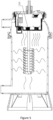
FIG. 4 illustrates a sectional view of the heater in the preferred embodiment of the present invention; -
FIG. 5 illustrates a sectional view of another position of the heater in the preferred embodiment of the present invention; -
FIG. 6 illustrates a schematic view of the anti-corrosion metal block in the preferred embodiment of the present invention; -
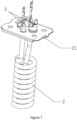
FIG. 7 illustrates a schematic view of the support in the preferred embodiment of the present invention; -
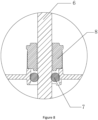
FIG. 8 illustrates a schematic view of fixing the power wire of the heater in the preferred embodiment of the present invention; -
FIG. 9 illustrates the use view of the heater in the preferred embodiment of the present invention. - The following will clearly and completely describe the technical solution in the embodiment of the present invention in combination with the drawings in the embodiment of the present invention; obviously, the described embodiments are only part of the embodiments of the present invention, not all of them. Based on the embodiments of the present invention, all other embodiments obtained by a person skilled in the field without making creative work belong to the scope of protection of the present invention.
- In the description of the present invention, it should be noted that the orientation or position relationship indicated by the terms "up", "down", "inside", "outside", "top/bottom", etc. is based on the orientation or position relationship shown in the drawings, which is only for the convenience of describing the present invention and simplifying the description, rather than indicating or implying that the device or element referred to must have a specific orientation, be constructed and operated in a specific orientation. Therefore, it cannot be understood as a limitation of the present invention. In addition, the terms "first" and "second" are only used to describe the purpose and cannot be understood as indicating or implying relative importance. In the description of the present invention, it should be noted that, unless otherwise specified and defined, the terms "installation", "set", "sleeve/connection", "connection", etc. should be understood in a broad sense. For example, "connection" can be wall mounted connection, removable connection, or integrated connection, which can be mechanical connection, electrical connection, direct connection, or indirect connection through intermediate media, it can be the connection between two assemblies. For those skilled in the art, they can understand the specific meaning of the above terms in the present invention.
- Referring to
FIGS. 1 to 9 , this embodiment provides a heater for a pool, which comprises atopple sensor 1, aheating assembly 2, abody 3 and a controller for driving theheating assembly 2 to heat or stop heating. Thebody 3 is provided with awater inlet 31 and awater outlet 32, and theheating assembly 2 is arranged in thebody 3 for convection heating of water flowing through thebody 3; - The
topple sensor 1 comprises a movingmember 11, afixing member 12 and asensor 13. Thefixing member 12 has a chamber for accommodating the movingmember 11, and the chamber has a taper; thesensor 13 is used to sense whether the relative position of the movingmember 11 and thefixing member 12 have changed; when thefixing member 12 topples over, the movingmember 11 moves relative to thefixing member 12, and thesensor 13 outputs a topple signal to the controller, so that the controller drives theheating assembly 2 to stop heating. - The heater for the pool outputs the topple signal through the change of the position of the
topple sensor 1 when thebody 3 topples over or not, and then controls the heater to stop heating after thebody 3 is topple. - In order to achieve the above anti toppling effect, the moving
member 11 is a magnet assembly, and thesensor 13 is a magnetic sensor and is arranged at the bottom of the chamber corresponding to thefixing member 12; when thefixing member 12 does not topple over, the movingmember 11 contacts the bottom of the chamber of thefixing member 12, and the magnetic sensor receives a first magnetic field strength signal; when thefixing member 12 topples over, the movingmember 11 is separated from the bottom of the chamber of thefixing member 12, and the magnetic sensor receives a second magnetic field strength signal; the strength of the first magnetic field strength signal is greater than the second magnetic field strength signal. - More specifically, the magnet assembly comprises a
magnet fixing base 111 and amagnet 112; themagnet 112 is arranged at the bottom of themagnet fixing base 111. Themagnet fixing base 111 is in the shape of a cone. - This embodiment further comprises an anti
dry heating assembly 4, which is connected to the controller; when the water level in thebody 3 is lower than a set threshold value, the antidry heating assembly 4 outputs an anti dry heating signal to the controller, so that the controller drives theheating assembly 2 to stop heating. - Specifically, the anti
dry heating assembly 4 is a float switch; when the water level is lower than a set threshold value, the float switch is disconnected. - In addition, during the use of the heater, it is better to keep the water temperature stable within a set threshold value, so that users will not have a bad experience because of the sudden cold and hot. Therefore, it further comprises a
temperature sensor 5, which is connected to the controller; thetemperature sensor 5 is used to detect the temperature in thebody 3. When the temperature exceeds a set threshold value, thetemperature sensor 5 outputs a temperature limiting signal to the controller so that the controller drives theheating assembly 2 to stop heating. Similarly, when the temperature is lower than a set threshold value, thetemperature sensor 5 outputs a temperature limiting signal to the controller so that the controller drives theheating assembly 2 to start heating. In this way, the water temperature can be maintained within a range. In this embodiment, theheating assembly 2 and thetemperature sensor 5 are fixed on thesame metal support 21, so that thetemperature sensor 5 can sense the water temperature more quickly and accurately during normal operation, and can collect more heat in the air in a larger area during dry heating, so as to achieve quick tripping response. - When the
heating assembly 2 works, the hot air moves upward. Therefore, thetemperature sensor 5 is set above theheating assembly 2 along the height direction of thebody 3 to detect the temperature change more accurately and timely. - In addition, the outer side of the
heating assembly 2 is provided with ananti-corrosion metal block 20. - The
anti-corrosion metal block 20 is conductive to the heated liquid, and the chemical property of theanti-corrosion metal block 20 is more active than that of theheating assembly 2. Theheating assembly 2 can be protected from corrosion by sacrificing theanti-corrosion metal block 20, and theanti-corrosion metal block 20 can be replaced regularly. Theanti-corrosion metal block 20 can be made of zinc alloy, magnesium alloy, aluminum alloy, etc. - The
water inlet 31 is arranged at the lower end of thebody 3 along the height direction, and thewater outlet 32 is arranged at the upper end of thebody 3 along the height direction. This is good for exhaust. - Moreover, in this embodiment, in order to avoid the problem of water leakage inside the heater caused by the pulling of the
power wire 6 of the heater, thepower line 6 is first clamped by the wire clip. The wire clip is made of hard material, which plays a fixing role and does not participate in the sealing. Therefore, the sealing structure will not be affected during the pulling of thepower line 6, and the leakage will not be caused by insufficient interference due to excessive deformation of the wire clip. - The sealing structure is realized through a
sealing ring 7 and a fixingcover plate 8, so the number of parts involved in the sealing is relatively small, the cumulative tolerance is lower, and the production tolerance is improved. - Referring to
FIG. 9 , this embodiment further provides a pool with heating function, which comprises apool body 9, awater pump 10 and the heater as described above; thewater pump 10 is connected between the water outlet of thepool body 9 and the water inlet of the heater, and the water outlet of the heater is connected to the water inlet of thepool body 9. - It will be apparent to those skilled in the art that various modifications and variation can be made in the present disclosure without departing from the spirit or scope of the disclosure. Thus, it is intended that the present disclosure cover the modifications and variations of this disclosure provided they come within the scope of the appended claims and their equivalents.
Claims (12)
- A heater for a pool, comprising:
a topple sensor; a heating assembly; a body; and a controller for driving the heating assembly to heat or stop heating,wherein the body is provided with a water inlet and a water outlet,wherein the heating assembly is arranged in the body for heating water flowing through the body,wherein the topple sensor comprises a moving member, a fixing member and a sensor, the fixing member being provided with a chamber for accommodating the moving member, and the chamber being provided with a taper, the sensor being used for sensing whether the relative position of the moving member and the fixing member changes, wherein when the fixing member topples over, the moving member moves relative to the fixing member, and the sensor outputs a toppling signal to the controller, so that the controller drives the heating assembly to stop heating. - The heater for a pool according to claim 1, wherein the moving member is a magnet assembly, and the sensor is a magnetic sensor and is arranged at the bottom of the chamber corresponding to the fixing member, wherein when the fixing member does not topple over, the moving member contacts the bottom of the chamber of the fixing member, and the magnetic sensor receives a first magnetic field strength signal, and wherein when the fixing member topples over, the moving member is separated from the bottom of the chamber of the fixing member, and the magnetic sensor receives a second magnetic field strength signal, the strength of the first magnetic field strength signal being greater than the second magnetic field strength signal.
- The heater for a pool according to claim 2, wherein the magnet assembly is a magnet fixing base and a magnet, the magnet being arranged at the bottom of the magnet fixing base.
- The heater for a pool according to claim 3, wherein the magnet fixing base is in the shape of a cone.
- The heater for a pool according to any of claims 1-4, further comprising an anti dry heating assembly connected to the controller, wherein when the water level in the body is lower than a set threshold value, the anti dry heating assembly outputs an anti dry heating signal to the controller, so that the controller drives the heating assembly to stop heating.
- The heater for a pool according to claim 5, wherein the anti dry heating assembly is a float switch, wherein when the water level is lower than a set threshold value, the float switch is turned off.
- The heater for a pool according to any preceding claim, further comprising a temperature sensor, which is connected with the controller, the temperature sensor being used to detect a temperature in the body, wherein when the temperature exceeds a set threshold value, the temperature sensor outputs a temperature limiting signal to the controller, so that the controller drives the heating assembly to stop heating.
- The heater for a pool according to claim 7, wherein the temperature sensor is arranged above the heating assembly along the height direction of the body.
- The heater for a pool according to claim 8, wherein the heating assembly and the temperature sensor are fixed on the same metal support.
- The heater for a pool according to any preceding claim, wherein the water inlet is arranged at the lower end of the body along the height direction, and the water outlet is arranged at the upper end of the body along the height direction.
- The heater for a pool according to any preceding claim, wherein the outer side of the heating assembly is provided with an anti-corrosion metal block, the anti-corrosion metal block being conductive to the heated liquid, and the chemical property of the anti-corrosion metal block is more active than that of the heating assembly.
- A pool with heating function, comprising a pool body, a water pump and a heater according to any of claims 1-11, the water pump being connected between a water outlet of the pool body and the water inlet of the heater, and the water outlet of the heater being connected to a water inlet of the pool body.
Priority Applications (1)
| Application Number | Priority Date | Filing Date | Title |
|---|---|---|---|
| EP26162085.0A EP4726145A3 (en) | 2021-12-24 | 2022-12-23 | A heater for a pool and a pool with heating function |
Applications Claiming Priority (1)
| Application Number | Priority Date | Filing Date | Title |
|---|---|---|---|
| CN202123295656.5U CN217423605U (en) | 2021-12-24 | 2021-12-24 | A pond that is used for heater in pond and takes heating function |
Related Child Applications (1)
| Application Number | Title | Priority Date | Filing Date |
|---|---|---|---|
| EP26162085.0A Division EP4726145A3 (en) | 2021-12-24 | 2022-12-23 | A heater for a pool and a pool with heating function |
Publications (2)
| Publication Number | Publication Date |
|---|---|
| EP4202155A1 true EP4202155A1 (en) | 2023-06-28 |
| EP4202155B1 EP4202155B1 (en) | 2026-03-04 |
Family
ID=83175238
Family Applications (2)
| Application Number | Title | Priority Date | Filing Date |
|---|---|---|---|
| EP22216621.7A Active EP4202155B1 (en) | 2021-12-24 | 2022-12-23 | A heater for a pool and a pool with heating function |
| EP26162085.0A Pending EP4726145A3 (en) | 2021-12-24 | 2022-12-23 | A heater for a pool and a pool with heating function |
Family Applications After (1)
| Application Number | Title | Priority Date | Filing Date |
|---|---|---|---|
| EP26162085.0A Pending EP4726145A3 (en) | 2021-12-24 | 2022-12-23 | A heater for a pool and a pool with heating function |
Country Status (3)
| Country | Link |
|---|---|
| EP (2) | EP4202155B1 (en) |
| CN (1) | CN217423605U (en) |
| ES (1) | ES3071108T3 (en) |
Citations (2)
| Publication number | Priority date | Publication date | Assignee | Title |
|---|---|---|---|---|
| CN2931674Y (en) * | 2006-07-03 | 2007-08-08 | 明达实业(厦门)有限公司 | Swimming pool filter structure |
| US20200024860A1 (en) * | 2018-07-18 | 2020-01-23 | Patrick GEORGOFF | Baby and kiddie pool sunless water heater with circulating pump |
Family Cites Families (4)
| Publication number | Priority date | Publication date | Assignee | Title |
|---|---|---|---|---|
| US4907418A (en) * | 1988-11-14 | 1990-03-13 | Defazio Louis C | Liquid heating system particularly for use with swimming pools or the like |
| KR100663967B1 (en) * | 2005-11-09 | 2007-01-02 | 고영호 | Hot water heater for hot water mat |
| CN2916480Y (en) * | 2006-04-04 | 2007-06-27 | 东莞虎邦五金塑胶制品有限公司 | pool heater |
| CN102235741A (en) * | 2011-07-22 | 2011-11-09 | 方春风 | Instant heating type constant-temperature online heater |
-
2021
- 2021-12-24 CN CN202123295656.5U patent/CN217423605U/en active Active
-
2022
- 2022-12-23 EP EP22216621.7A patent/EP4202155B1/en active Active
- 2022-12-23 ES ES22216621T patent/ES3071108T3/en active Active
- 2022-12-23 EP EP26162085.0A patent/EP4726145A3/en active Pending
Patent Citations (2)
| Publication number | Priority date | Publication date | Assignee | Title |
|---|---|---|---|---|
| CN2931674Y (en) * | 2006-07-03 | 2007-08-08 | 明达实业(厦门)有限公司 | Swimming pool filter structure |
| US20200024860A1 (en) * | 2018-07-18 | 2020-01-23 | Patrick GEORGOFF | Baby and kiddie pool sunless water heater with circulating pump |
Also Published As
| Publication number | Publication date |
|---|---|
| ES3071108T3 (en) | 2026-06-19 |
| EP4726145A2 (en) | 2026-04-15 |
| CN217423605U (en) | 2022-09-13 |
| EP4202155B1 (en) | 2026-03-04 |
| EP4726145A3 (en) | 2026-07-15 |
Similar Documents
| Publication | Publication Date | Title |
|---|---|---|
| CN206843048U (en) | Soda water machine | |
| CN203196652U (en) | Dryout-free constant-water-level constant-temperature water bath | |
| EP4202155B1 (en) | A heater for a pool and a pool with heating function | |
| CN218033706U (en) | Heating inner container assembly and electric water heater | |
| CN113483485B (en) | Heating method of instant electric water heater and instant electric water heater | |
| CN203196651U (en) | Dryout-free constant-water-level constant-temperature water bath | |
| CN205390937U (en) | Heating cup who shows temperature | |
| CN216048314U (en) | Instant electric water heater | |
| CN102563833B (en) | Electric water heater with sealed outlet for faucet, and water flow switch and heat protector of electric water heater | |
| CN215809536U (en) | Oil slurry cooling device | |
| CN2319747Y (en) | Secondary heating electric water heater | |
| CN204970877U (en) | Energy -saving water dispenser | |
| CN201448448U (en) | Temperature control valve | |
| CN204592700U (en) | High sensitivity water flow sensing unit | |
| CN210241958U (en) | Water constant temperature device | |
| CN112443982B (en) | Leakage detection device for pipeline joint of heat exchanger inside water heater | |
| CN211011915U (en) | Air energy water heater | |
| CN210345851U (en) | Instant heating structure and instant heating equipment | |
| CN207990996U (en) | An electric wall-hung furnace | |
| CN208606384U (en) | Single port Horizontal single-pipe Natural Circulation Combined type electric hot water apparatus | |
| CN205481790U (en) | Electromagnetism water storage formula electric water heater heating pipe structure | |
| CN219510263U (en) | Electric heating control mechanism of connection type electric heating faucet | |
| CN2177193Y (en) | Automatic continuous magnetizing water boiling device | |
| CN224140625U (en) | An electric coffee maker | |
| WO2021077816A1 (en) | Air-energy water heater |
Legal Events
| Date | Code | Title | Description |
|---|---|---|---|
| PUAI | Public reference made under article 153(3) epc to a published international application that has entered the european phase |
Free format text: ORIGINAL CODE: 0009012 |
|
| STAA | Information on the status of an ep patent application or granted ep patent |
Free format text: STATUS: THE APPLICATION HAS BEEN PUBLISHED |
|
| AK | Designated contracting states |
Kind code of ref document: A1 Designated state(s): AL AT BE BG CH CY CZ DE DK EE ES FI FR GB GR HR HU IE IS IT LI LT LU LV MC ME MK MT NL NO PL PT RO RS SE SI SK SM TR |
|
| STAA | Information on the status of an ep patent application or granted ep patent |
Free format text: STATUS: REQUEST FOR EXAMINATION WAS MADE |
|
| 17P | Request for examination filed |
Effective date: 20231222 |
|
| RBV | Designated contracting states (corrected) |
Designated state(s): AL AT BE BG CH CY CZ DE DK EE ES FI FR GB GR HR HU IE IS IT LI LT LU LV MC ME MK MT NL NO PL PT RO RS SE SI SK SM TR |
|
| RAP1 | Party data changed (applicant data changed or rights of an application transferred) |
Owner name: INTEX MARKETING LTD. |
|
| GRAJ | Information related to disapproval of communication of intention to grant by the applicant or resumption of examination proceedings by the epo deleted |
Free format text: ORIGINAL CODE: EPIDOSDIGR1 |
|
| GRAP | Despatch of communication of intention to grant a patent |
Free format text: ORIGINAL CODE: EPIDOSNIGR1 |
|
| RIC1 | Information provided on ipc code assigned before grant |
Ipc: E04H 4/12 20060101AFI20250716BHEP |
|
| GRAP | Despatch of communication of intention to grant a patent |
Free format text: ORIGINAL CODE: EPIDOSNIGR1 |
|
| STAA | Information on the status of an ep patent application or granted ep patent |
Free format text: STATUS: GRANT OF PATENT IS INTENDED |
|
| INTG | Intention to grant announced |
Effective date: 20250923 |
|
| GRAS | Grant fee paid |
Free format text: ORIGINAL CODE: EPIDOSNIGR3 |
|
| GRAA | (expected) grant |
Free format text: ORIGINAL CODE: 0009210 |
|
| STAA | Information on the status of an ep patent application or granted ep patent |
Free format text: STATUS: THE PATENT HAS BEEN GRANTED |
|
| AK | Designated contracting states |
Kind code of ref document: B1 Designated state(s): AL AT BE BG CH CY CZ DE DK EE ES FI FR GB GR HR HU IE IS IT LI LT LU LV MC ME MK MT NL NO PL PT RO RS SE SI SK SM TR |
|
| REG | Reference to a national code |
Ref country code: CH Ref legal event code: F10 Free format text: ST27 STATUS EVENT CODE: U-0-0-F10-F00 (AS PROVIDED BY THE NATIONAL OFFICE) Effective date: 20260304 Ref country code: GB Ref legal event code: FG4D |
|
| REG | Reference to a national code |
Ref country code: IE Ref legal event code: FG4D |
|
| REG | Reference to a national code |
Ref country code: DE Ref legal event code: R096 Ref document number: 602022031554 Country of ref document: DE |
|
| REG | Reference to a national code |
Ref country code: ES Ref legal event code: FG2A Ref document number: 3071108 Country of ref document: ES Kind code of ref document: T3 Effective date: 20260619 |
|
| PG25 | Lapsed in a contracting state [announced via postgrant information from national office to epo] |
Ref country code: RS Free format text: LAPSE BECAUSE OF FAILURE TO SUBMIT A TRANSLATION OF THE DESCRIPTION OR TO PAY THE FEE WITHIN THE PRESCRIBED TIME-LIMIT Effective date: 20260604 |
|
| REG | Reference to a national code |
Ref country code: NL Ref legal event code: MP Effective date: 20260304 |
|
| PG25 | Lapsed in a contracting state [announced via postgrant information from national office to epo] |
Ref country code: PL Free format text: LAPSE BECAUSE OF FAILURE TO SUBMIT A TRANSLATION OF THE DESCRIPTION OR TO PAY THE FEE WITHIN THE PRESCRIBED TIME-LIMIT Effective date: 20260304 |
|
| PG25 | Lapsed in a contracting state [announced via postgrant information from national office to epo] |
Ref country code: GR Free format text: LAPSE BECAUSE OF FAILURE TO SUBMIT A TRANSLATION OF THE DESCRIPTION OR TO PAY THE FEE WITHIN THE PRESCRIBED TIME-LIMIT Effective date: 20260605 |
|
| REG | Reference to a national code |
Ref country code: LT Ref legal event code: MG9D |
|
| PG25 | Lapsed in a contracting state [announced via postgrant information from national office to epo] |
Ref country code: LT Free format text: LAPSE BECAUSE OF FAILURE TO SUBMIT A TRANSLATION OF THE DESCRIPTION OR TO PAY THE FEE WITHIN THE PRESCRIBED TIME-LIMIT Effective date: 20260304 |
|
| PG25 | Lapsed in a contracting state [announced via postgrant information from national office to epo] |
Ref country code: NO Free format text: LAPSE BECAUSE OF FAILURE TO SUBMIT A TRANSLATION OF THE DESCRIPTION OR TO PAY THE FEE WITHIN THE PRESCRIBED TIME-LIMIT Effective date: 20260604 |
|
| PG25 | Lapsed in a contracting state [announced via postgrant information from national office to epo] |
Ref country code: SE Free format text: LAPSE BECAUSE OF FAILURE TO SUBMIT A TRANSLATION OF THE DESCRIPTION OR TO PAY THE FEE WITHIN THE PRESCRIBED TIME-LIMIT Effective date: 20260304 Ref country code: FI Free format text: LAPSE BECAUSE OF FAILURE TO SUBMIT A TRANSLATION OF THE DESCRIPTION OR TO PAY THE FEE WITHIN THE PRESCRIBED TIME-LIMIT Effective date: 20260304 |
|
| PG25 | Lapsed in a contracting state [announced via postgrant information from national office to epo] |
Ref country code: HR Free format text: LAPSE BECAUSE OF FAILURE TO SUBMIT A TRANSLATION OF THE DESCRIPTION OR TO PAY THE FEE WITHIN THE PRESCRIBED TIME-LIMIT Effective date: 20260304 |
|
| PG25 | Lapsed in a contracting state [announced via postgrant information from national office to epo] |
Ref country code: LV Free format text: LAPSE BECAUSE OF FAILURE TO SUBMIT A TRANSLATION OF THE DESCRIPTION OR TO PAY THE FEE WITHIN THE PRESCRIBED TIME-LIMIT Effective date: 20260304 |
|
| PG25 | Lapsed in a contracting state [announced via postgrant information from national office to epo] |
Ref country code: BG Free format text: LAPSE BECAUSE OF FAILURE TO SUBMIT A TRANSLATION OF THE DESCRIPTION OR TO PAY THE FEE WITHIN THE PRESCRIBED TIME-LIMIT Effective date: 20260304 |