EP4202017A1 - Usine et procédé de conversion de matière première plastique en combustible - Google Patents
Usine et procédé de conversion de matière première plastique en combustible Download PDFInfo
- Publication number
- EP4202017A1 EP4202017A1 EP21217838.8A EP21217838A EP4202017A1 EP 4202017 A1 EP4202017 A1 EP 4202017A1 EP 21217838 A EP21217838 A EP 21217838A EP 4202017 A1 EP4202017 A1 EP 4202017A1
- Authority
- EP
- European Patent Office
- Prior art keywords
- raw material
- temperature
- oil
- plastic
- reactor
- Prior art date
- Legal status (The legal status is an assumption and is not a legal conclusion. Google has not performed a legal analysis and makes no representation as to the accuracy of the status listed.)
- Pending
Links
- 229920003023 plastic Polymers 0.000 title claims abstract description 86
- 239000004033 plastic Substances 0.000 title claims abstract description 86
- 239000002994 raw material Substances 0.000 title claims abstract description 71
- 239000000446 fuel Substances 0.000 title claims abstract description 47
- 238000006243 chemical reaction Methods 0.000 title claims abstract description 26
- 238000000034 method Methods 0.000 title claims description 47
- 230000008569 process Effects 0.000 title claims description 42
- 239000000463 material Substances 0.000 claims abstract description 89
- 238000001149 thermolysis Methods 0.000 claims abstract description 69
- 238000004821 distillation Methods 0.000 claims abstract description 14
- 238000012545 processing Methods 0.000 claims abstract description 7
- 238000003860 storage Methods 0.000 claims abstract description 7
- 239000007789 gas Substances 0.000 claims description 106
- 238000010438 heat treatment Methods 0.000 claims description 32
- 238000001035 drying Methods 0.000 claims description 27
- QVGXLLKOCUKJST-UHFFFAOYSA-N atomic oxygen Chemical compound [O] QVGXLLKOCUKJST-UHFFFAOYSA-N 0.000 claims description 23
- 229910052760 oxygen Inorganic materials 0.000 claims description 23
- 239000001301 oxygen Substances 0.000 claims description 23
- 239000007788 liquid Substances 0.000 claims description 21
- 238000011084 recovery Methods 0.000 claims description 17
- OKTJSMMVPCPJKN-UHFFFAOYSA-N Carbon Chemical compound [C] OKTJSMMVPCPJKN-UHFFFAOYSA-N 0.000 claims description 15
- 238000000605 extraction Methods 0.000 claims description 11
- 239000012530 fluid Substances 0.000 claims description 11
- 230000005484 gravity Effects 0.000 claims description 11
- 238000000926 separation method Methods 0.000 claims description 11
- 229910052799 carbon Inorganic materials 0.000 claims description 6
- 230000007246 mechanism Effects 0.000 claims description 5
- 230000001105 regulatory effect Effects 0.000 claims description 5
- 239000007787 solid Substances 0.000 claims description 5
- XLYOFNOQVPJJNP-UHFFFAOYSA-N water Substances O XLYOFNOQVPJJNP-UHFFFAOYSA-N 0.000 claims description 5
- 230000001419 dependent effect Effects 0.000 claims description 3
- 239000003921 oil Substances 0.000 description 67
- 239000000047 product Substances 0.000 description 12
- 239000003054 catalyst Substances 0.000 description 8
- -1 polyethylene Polymers 0.000 description 8
- 150000002430 hydrocarbons Chemical class 0.000 description 7
- 238000004519 manufacturing process Methods 0.000 description 7
- 239000000203 mixture Substances 0.000 description 7
- 230000008929 regeneration Effects 0.000 description 7
- 238000011069 regeneration method Methods 0.000 description 7
- 239000002699 waste material Substances 0.000 description 7
- 229930195733 hydrocarbon Natural products 0.000 description 6
- 239000004698 Polyethylene Substances 0.000 description 5
- 239000004743 Polypropylene Substances 0.000 description 5
- 239000004793 Polystyrene Substances 0.000 description 5
- 230000001276 controlling effect Effects 0.000 description 5
- 239000003915 liquefied petroleum gas Substances 0.000 description 5
- 238000012986 modification Methods 0.000 description 5
- 230000004048 modification Effects 0.000 description 5
- 238000010521 absorption reaction Methods 0.000 description 4
- XECAHXYUAAWDEL-UHFFFAOYSA-N acrylonitrile butadiene styrene Chemical compound C=CC=C.C=CC#N.C=CC1=CC=CC=C1 XECAHXYUAAWDEL-UHFFFAOYSA-N 0.000 description 4
- 239000004676 acrylonitrile butadiene styrene Substances 0.000 description 4
- 229920000122 acrylonitrile butadiene styrene Polymers 0.000 description 4
- 239000012141 concentrate Substances 0.000 description 4
- 239000000295 fuel oil Substances 0.000 description 4
- 229920001903 high density polyethylene Polymers 0.000 description 4
- 239000004700 high-density polyethylene Substances 0.000 description 4
- 229920001684 low density polyethylene Polymers 0.000 description 4
- 239000004702 low-density polyethylene Substances 0.000 description 4
- VNWKTOKETHGBQD-UHFFFAOYSA-N methane Chemical compound C VNWKTOKETHGBQD-UHFFFAOYSA-N 0.000 description 4
- 239000005020 polyethylene terephthalate Substances 0.000 description 4
- 229920000139 polyethylene terephthalate Polymers 0.000 description 4
- 230000009467 reduction Effects 0.000 description 4
- 239000000126 substance Substances 0.000 description 4
- 238000012546 transfer Methods 0.000 description 4
- 150000001336 alkenes Chemical class 0.000 description 3
- 239000006229 carbon black Substances 0.000 description 3
- 238000010276 construction Methods 0.000 description 3
- 238000001816 cooling Methods 0.000 description 3
- 238000009792 diffusion process Methods 0.000 description 3
- 238000011049 filling Methods 0.000 description 3
- 239000002184 metal Substances 0.000 description 3
- 239000004215 Carbon black (E152) Substances 0.000 description 2
- NINIDFKCEFEMDL-UHFFFAOYSA-N Sulfur Chemical compound [S] NINIDFKCEFEMDL-UHFFFAOYSA-N 0.000 description 2
- ATJFFYVFTNAWJD-UHFFFAOYSA-N Tin Chemical group [Sn] ATJFFYVFTNAWJD-UHFFFAOYSA-N 0.000 description 2
- 230000008901 benefit Effects 0.000 description 2
- 230000015572 biosynthetic process Effects 0.000 description 2
- 239000012467 final product Substances 0.000 description 2
- 239000003350 kerosene Substances 0.000 description 2
- 238000012423 maintenance Methods 0.000 description 2
- 239000003345 natural gas Substances 0.000 description 2
- JRZJOMJEPLMPRA-UHFFFAOYSA-N olefin Natural products CCCCCCCC=C JRZJOMJEPLMPRA-UHFFFAOYSA-N 0.000 description 2
- 239000002245 particle Substances 0.000 description 2
- 239000003208 petroleum Substances 0.000 description 2
- 229920000573 polyethylene Polymers 0.000 description 2
- 229920001155 polypropylene Polymers 0.000 description 2
- 229920002223 polystyrene Polymers 0.000 description 2
- 238000000197 pyrolysis Methods 0.000 description 2
- 238000003908 quality control method Methods 0.000 description 2
- 239000003507 refrigerant Substances 0.000 description 2
- 229910001220 stainless steel Inorganic materials 0.000 description 2
- 229910052717 sulfur Inorganic materials 0.000 description 2
- 239000011593 sulfur Substances 0.000 description 2
- 238000009827 uniform distribution Methods 0.000 description 2
- 206010037660 Pyrexia Diseases 0.000 description 1
- 238000013019 agitation Methods 0.000 description 1
- 238000009835 boiling Methods 0.000 description 1
- 125000004432 carbon atom Chemical group C* 0.000 description 1
- 230000003197 catalytic effect Effects 0.000 description 1
- 239000000571 coke Substances 0.000 description 1
- 238000002485 combustion reaction Methods 0.000 description 1
- 150000001875 compounds Chemical class 0.000 description 1
- 238000009833 condensation Methods 0.000 description 1
- 230000005494 condensation Effects 0.000 description 1
- 239000002826 coolant Substances 0.000 description 1
- 239000000498 cooling water Substances 0.000 description 1
- 238000013461 design Methods 0.000 description 1
- 238000009826 distribution Methods 0.000 description 1
- 230000008030 elimination Effects 0.000 description 1
- 238000003379 elimination reaction Methods 0.000 description 1
- 230000002708 enhancing effect Effects 0.000 description 1
- 239000003344 environmental pollutant Substances 0.000 description 1
- 238000002309 gasification Methods 0.000 description 1
- 231100001261 hazardous Toxicity 0.000 description 1
- 239000000383 hazardous chemical Substances 0.000 description 1
- 230000036541 health Effects 0.000 description 1
- 239000010763 heavy fuel oil Substances 0.000 description 1
- 238000000265 homogenisation Methods 0.000 description 1
- 238000009434 installation Methods 0.000 description 1
- 238000002955 isolation Methods 0.000 description 1
- 150000002576 ketones Chemical class 0.000 description 1
- 238000010169 landfilling Methods 0.000 description 1
- 239000012263 liquid product Substances 0.000 description 1
- 239000003595 mist Substances 0.000 description 1
- 238000002156 mixing Methods 0.000 description 1
- 239000000123 paper Substances 0.000 description 1
- 239000003209 petroleum derivative Substances 0.000 description 1
- 231100000719 pollutant Toxicity 0.000 description 1
- 238000002360 preparation method Methods 0.000 description 1
- 230000003134 recirculating effect Effects 0.000 description 1
- 238000004064 recycling Methods 0.000 description 1
- 230000001172 regenerating effect Effects 0.000 description 1
- 239000011343 solid material Substances 0.000 description 1
- 239000010935 stainless steel Substances 0.000 description 1
- 238000006467 substitution reaction Methods 0.000 description 1
- 229920001169 thermoplastic Polymers 0.000 description 1
- 229920001187 thermosetting polymer Polymers 0.000 description 1
- 239000004416 thermosoftening plastic Substances 0.000 description 1
- 238000009423 ventilation Methods 0.000 description 1
- 238000005303 weighing Methods 0.000 description 1
- 239000002023 wood Substances 0.000 description 1
Images


Classifications
-
- C—CHEMISTRY; METALLURGY
- C10—PETROLEUM, GAS OR COKE INDUSTRIES; TECHNICAL GASES CONTAINING CARBON MONOXIDE; FUELS; LUBRICANTS; PEAT
- C10G—CRACKING HYDROCARBON OILS; PRODUCTION OF LIQUID HYDROCARBON MIXTURES, e.g. BY DESTRUCTIVE HYDROGENATION, OLIGOMERISATION, POLYMERISATION; RECOVERY OF HYDROCARBON OILS FROM OIL-SHALE, OIL-SAND, OR GASES; REFINING MIXTURES MAINLY CONSISTING OF HYDROCARBONS; REFORMING OF NAPHTHA; MINERAL WAXES
- C10G1/00—Production of liquid hydrocarbon mixtures from oil-shale, oil-sand, or non-melting solid carbonaceous or similar materials, e.g. wood, coal
- C10G1/10—Production of liquid hydrocarbon mixtures from oil-shale, oil-sand, or non-melting solid carbonaceous or similar materials, e.g. wood, coal from rubber or rubber waste
-
- C—CHEMISTRY; METALLURGY
- C10—PETROLEUM, GAS OR COKE INDUSTRIES; TECHNICAL GASES CONTAINING CARBON MONOXIDE; FUELS; LUBRICANTS; PEAT
- C10B—DESTRUCTIVE DISTILLATION OF CARBONACEOUS MATERIALS FOR PRODUCTION OF GAS, COKE, TAR, OR SIMILAR MATERIALS
- C10B47/00—Destructive distillation of solid carbonaceous materials with indirect heating, e.g. by external combustion
- C10B47/28—Other processes
- C10B47/32—Other processes in ovens with mechanical conveying means
- C10B47/44—Other processes in ovens with mechanical conveying means with conveyor-screws
-
- C—CHEMISTRY; METALLURGY
- C10—PETROLEUM, GAS OR COKE INDUSTRIES; TECHNICAL GASES CONTAINING CARBON MONOXIDE; FUELS; LUBRICANTS; PEAT
- C10B—DESTRUCTIVE DISTILLATION OF CARBONACEOUS MATERIALS FOR PRODUCTION OF GAS, COKE, TAR, OR SIMILAR MATERIALS
- C10B53/00—Destructive distillation, specially adapted for particular solid raw materials or solid raw materials in special form
- C10B53/07—Destructive distillation, specially adapted for particular solid raw materials or solid raw materials in special form of solid raw materials consisting of synthetic polymeric materials, e.g. tyres
-
- C—CHEMISTRY; METALLURGY
- C10—PETROLEUM, GAS OR COKE INDUSTRIES; TECHNICAL GASES CONTAINING CARBON MONOXIDE; FUELS; LUBRICANTS; PEAT
- C10B—DESTRUCTIVE DISTILLATION OF CARBONACEOUS MATERIALS FOR PRODUCTION OF GAS, COKE, TAR, OR SIMILAR MATERIALS
- C10B57/00—Other carbonising or coking processes; Features of destructive distillation processes in general
- C10B57/08—Non-mechanical pretreatment of the charge, e.g. desulfurization
- C10B57/10—Drying
Definitions
- the present disclosure is related to the field of processing plastic material through continuous thermocatalytic conversion into fuel products.
- Plastics have been one of the materials with the fastest growth because of their wide range of applications due to versatility and relatively low cost. Since the duration of life of plastic products is relatively small, there is a vast plastics waste stream that reaches each year to the final recipients thereby creating severe environmental hazards. Since the disposal of post-consumer plastics is continuously being constrained by relevant governmental legislations and escalating costs, there is considerable demand for alternatives to disposal or land filling with waste plastics. Such alternatives may include source reduction, reuse, recycling, and recovery of the inherent energy value through waste-to-energy incineration and processed fuel applications. Each of these options potentially reduces waste and conserves natural resources.
- thermolysis or pyrolysis
- pyrolysis is a well-known method of chemical reaction in which a relatively large compound is broken down into molecules due to high temperatures.
- Such process for converting waste plastic into liquid fuels is generally acknowledged as a convenient way to handle waste plastic, since the cost is manageable, and the final product (liquid fuel) may have properties that are more or less similar to the common petroleum fuels.
- the products that are deriving from the thermolysis of plastic provide the advantage of not containing any sulfur, as the petroleum products do, thereby being more environmentally friendly, since sulfur is a known pollutant that also affects the health of the general public.
- Conventional plants however, that try to convert waste plastic to usable fuel do show some drawbacks, mainly related to the thermal efficiency of the overall process.
- thermolysis reactor feedstock system, drying apparatus
- the various sections of conventional plants are not interconnected, thereby each one requiring its own external source of energy to operate, while at the same time a significant amount of heating energy that is produced during each sections operation is lost, thereby resulting in a relatively low thermal efficiency of the overall plant and consequently to questionable quality of the final products.
- the described plant for converting plastic raw material into usable fuel is designed and based on a continuous closed operation cycle where each section of the plant interacts with each other in a way which achieves maximum energy efficiency.
- a relatively compact/controllable size of the plant is achieved, thereby allowing the installation of such a plant in a quite fast and precise manner in any workplace.
- Such arrangement further allows for a continuous thermolysis reaction and a continuous extraction of syngas from the reactor, thus enhancing the efficiency of the overall plant and process.
- a plant configured to convert plastic materials into usable fuel, comprising, a feedstock supply system for the storage of the plastic raw material, a material preparatory system for preparing the raw material prior to the conversion, a preheating line for increasing the temperature of the plastic raw material, a thermolysis reactor for processing the plastic raw material, one or more oil condensers that are connected to the material preparatory system and a distillation tower that is connected to the one or moil oil condensers.
- the plant comprises -an oil boiler distillatory that is connected to the thermolysis reactor, and an oil preheating chamber that is connected to the oil boiler distillatory and to the thermolysis reactor.
- the plant comprises one or more three-phase separators that are connected to the distillation tower, for separating a fluid from the distillation tower to gas, oil and water phases.
- the material preparatory system comprises at least two drying apparatuses, wherein the raw material is directed towards the at least two drying apparatus at an ambient temperature and wherein the drying apparatus heats the raw material to reach a temperature between 70-90°C, said temperature being regulated by one or more gas valves.
- the material preparatory system further comprises an oxygen extraction apparatus that is connected to the at least two drying apparatus and is configured to receive the raw material at a temperature between 70-90°C, remove the oxygen from the material and increase the temperature of the raw material in the region of 120-140 °C.
- the preheating line comprises a plurality of heat exchanging units wherein said plurality of heat exchanging units are arranged in series and comprises a first feeding heat exchanger configured to receive raw material in solid state at a first temperature and a first conveyor heat exchanger that is connected to the first feeding heat exchanger, a second feeding heat exchanger that is configured to guide the plastic material in molten state towards a second conveyor heat exchanger at a second temperature, wherein the first temperature of the solid state is in between 100-160 °C, optionally 120-140°C, and the second temperature of the molten state is between 180-240°C, optionally 200-220 °C.
- the thermolysis reactor comprises a reaction chamber for receiving the material after the preheating line, at least one gas burner for producing exhaust gases, an agitating device for agitating, heating and homogenising the plastic material and a carbon rejection device that is connected to the reaction chamber.
- thermolysis reactor is provided with an exhaust gases collector that is connected to the at least one gas burner, wherein said exhaust gases exhaust gases are distributed within the reactor through ducts that form one or more heating jackets that surround the reactor and wherein the exhaust gases pass through the agitating device.
- the oil boiler distillatory comprises at least one gas burner configured to produce exhaust gases for heating the oil boiler and an exhaust gas passage chamber and a syngas passage chamber, wherein the syngas is a synergy of gas resulting from the thermolysis reactor and the oil boiler distillatory.
- the one or more oil condensers comprise at least two heat exchanging units, a plurality of control valves and a temperature control system wherein the one or more oil condensers are designed such that when the syngas in the oil condensers, they are condensed to a temperature between 150-180°C with the use of water.
- the one or more three-phase separators are in the form of a vessel and comprise: a primary separation section comprising an inlet for receiving a fluid from the distillation tower, wherein when the fluid enters the vessel comes in direct contact with a deflector, thereby causing separation of the fluid to liquid in the form of droplets and gas phase, a gravity section wherein the droplets are separated by gravity means, a coalescing section and a liquid collection section for receiving the liquid that was removed from the gases in the primary, the gravity and the coalescing section.
- the feedstock supply system comprises at least one feed silo for storing the raw material, a shredder for shredding the raw material into suitable shape and size and a screw conveyor system for transferring the raw material towards the material preparatory system, wherein the at least one feed silo comprises at least one load cell configure to weight the raw material.
- the screw conveyor system comprises a linking mechanism that is designed such that it allows to connect an additional feed silo with additional raw material to be transferred towards the material preparatory system.
- a process of converting plastic raw material to usable fuel comprising the steps of:
- the process comprises the steps of transferring syngas that is derived from the thermolysis reactor to an oil preheating chamber and transferring syngas that is derived from an oil boiler distillatory to an oil preheating chamber.
- the process comprises transferring the syngas that is derived both from the thermolysis reactor and the oil boiler distillatory from the oil preheating chamber to at least two drying apparatuses.
- the process comprises the step of transferring syngas from the at least two drying apparatuses to at least one oil condensers and transferring of the syngas from the at least two oil condensers to a 3-phase separator.
- the process comprises the steps of
- the process comprises the step of rejecting carbon residues via a carbon rejecting system.
- first the terms “first,” “second,” etc. may be used herein to describe various elements, components, regions, layers, sections, and/or parameters, these elements, components, regions, layers, sections, and/or parameters should not be limited by these terms. These terms are only used to distinguish one element, component, region, layer, or section from another region, layer, or section. Thus, a first element, component, region, layer, or section discussed herein could be termed a second element, component, region, layer, or section without departing from the teachings of the present disclosure .
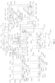
- FIG. 1 and partial views 1a, 1b, 1c of the same Figure 1 illustrate the various stations of the plant for converting plastic material to usable fuel.
- the plant comprises a feedstock supply system that may comprise two or more feed silos (004, 011), a material preparatory system for preparing the raw material prior to the conversion, wherein the material preparatory system may comprise at least two drying apparatuses (101, 104), a preheating line (201, 202) for increasing the temperature of the plastic raw material, a thermolysis reactor (301) for processing the raw material, one or moil oil condensers (501, 502) that are connected to the material preparatory system and more specifically to the at least two drying apparatuses (101, 104) and a distillation tower (511, 513) that is connected to the one or more oil condensers (501, 502).
- a feedstock supply system may comprise two or more feed silos (004, 011)
- a material preparatory system for preparing the raw material prior to the conversion
- the plant may further comprise an oil boiler distillatory (401) that is connected to the thermolysis reactor (301) and an oil preheating chamber (307) that is connected to the oil boiler distillatory (401) and to the thermolysis reactor (301).
- the plant may also comprise one or more three-phase separators (512, 514) that are connected to the distillation tower (511, 513) and their purpose is to separate the fluid to gas and oil and water phase.
- Such arrangement and interconnection of the various components of the conversion plant is advantageous since it provides a continuous closed operation cycle where each section of the plant interacts with each other, thereby achieving the maximum possible energy efficiency.
- the feedstock supply system may also comprise a shredding device and a screw conveyor.
- the plastic raw material in its initial shape which may be cylindrical, or sheet shaped etc., is transferred to the shredding device where the relatively large parts are shredded and thus minimized to suitable shape and size.
- an overband magnet may also be used to separate the any metal residues from the raw material in an effective and quick manner.
- the shredding device forms the plastic material preferably in cylindrical shaped particles ('spheres') with a maximum diameter of 10mm. Afterwards, such spheres are guided through conveyors to holding silos where they are stored before being fed to the feed silos.
- the plastic materials that are suitable for the conversion according to the present disclosure may be, but not limited to, PE (polyethylene), PET (polyethylene terephthalate), HDPE (high density polyethylene), LDPE (low density polyethylene), PP (polypropylene), PS (polystyrene), ABS (acrylonitrile-butadiene-styrene copolymer).
- PE polyethylene
- PET polyethylene terephthalate
- HDPE high density polyethylene
- LDPE low density polyethylene
- PP polypropylene
- PS polystyrene
- ABS acrylonitrile-butadiene-styrene copolymer
- the most preferred feedstock from the above list of materials for the production of liquid hydrocarbons are the PE, PP and PS thermoplastics which with the addition of thermosetting plastics, wood, and paper to the feedstock results to the formation of carbonous substances and lowers the rate and yield of liquid products.
- thermolysis products are directly related to the chemical composition and chemical structure of the plastics, since the chemical composition of the feedstock affects the thermolysis process. It has to be noted, that is of significant importance if the plastic feedstock contains PVC, since the PVC thermolysis the resulting products may contain HCI that is found to be hazardous for the fuels. In that case wherein the feedstock comprises PVC the plant should also comprise a re-treatment system to remove Hcl from the resulting pyrolysis products.
- the thermolysis products may be grouped as petroleum gases, petrol, kerosene, diesel and WAX (>C 50 ).
- the above-mentioned fuels may contain hydrocarbon group with different carbon chain lengths as given in below Table1.
- hydrocarbons such as boiling range, phase of products at room temperature etc. Table 1. Hydrocarbon range in commercial fuels Fuels LPG Petrol Kerosene Diesel Heavy Fuel oil Hydrocarbons C 1 to C 4 C 5 to C 10 C 10 to C 16 C 14 to C 20 C 20 to C 70
- the feedstock supply system may comprise two or more feed silos.
- a different type of plastic may be stored in each silo, such as but not limited to: PE (polyethylene), PET (polyethylene terephthalate), HDPE (high density polyethylene), LDPE (low density polyethylene), PP (polypropylene), PS (polystyrene), ABS (acrylonitrile-butadiene-styrene copolymer) or a mixture of the above.
- PE polyethylene
- PET polyethylene terephthalate
- HDPE high density polyethylene
- LDPE low density polyethylene
- PP polypropylene
- PS polystyrene
- ABS acrylonitrile-butadiene-styrene copolymer
- the plant has the flexibility to select a percentage of each type of plastic each time and make a mixture of different types depending on the availability of raw materials and the target parameters set for the final products, the desired "recipe" is selected each time to produce high quality liquid fuel in the best and most efficient way for the operation of the plant.
- feedstock is loaded into a hopper (001) and is led for storage via a screw conveyor network in weighing silos (004, 011, 016, ).
- the structured way of connecting the screw conveyors (010, 020, 7), allows the addition of storage silo (011, 016...) without requiring changes to the overall mechanical equipment, making the feedstock supply system easily expandable from, for example 1 to 9 silos.
- Each silo (004, 011, 016, ...) may be mounted on load cells (005, 012, 018, ). At the bottom of each silo, for example at its outlet, there may be a proportional flow valve (006) which is configured to control the flow of raw material coming out of the silo. Additionally, under each silo there may be located a conveyor link (007, 042). In detail, the material coming out of the silo is inserted in the conveyor link (007). Conveyor link is designed to have appropriate ports where screw conveyors (009, 010, 020, ...) can be connected and through them material to be directed to the next station of the plant.
- the construction of the conveyor link (007) is such that it allows the connection of screw conveyors between the silos (009, 010, 020, ...) so that a network of screw conveyors can be created. In this way, the mixing of the raw materials is achieved depending on the percentage of raw material from each silo, for the completion of the recipe. Maintenance of the overall equipment is also facilitated since it is not required to interrupt the entire production process.
- a material preparatory system is used for preparing the raw material prior to the thermolysis reaction.
- the purpose of this system is to deduct humidity and oxygen from the plastic material and calculate the quantity of the material that will be further processed.
- the material preparatory system comprises at least two drying apparatus (101, 104). Feedstock is guided through a screw conveyor network (010, 020,) from the feed silos (004, 011,...) to the dryers (101, 104). Said dryers may be mounted on load cells that ensure the precision of the quantity of the material to be processed.
- the dryers may be of cylindrical shape and each of them may comprise a screw conveyor for filling and recirculating the plastic material.
- the dryers (101, 104) may also comprise one or more gas heat exchangers for diffusing relatively hot air to the plastic material during the drying process.
- the drying apparatus (101, 104) may be designed such that they comprise two heating jackets thereby allowing the gases to pass and the necessary heat to be transferred to the plastic material.
- the plastic material enters the at least two drying apparatus at an ambient temperature and is heated to a temperature between 70-90°C. In an embodiment, this preheating of the material is achieved by heat recovery the recirculation of syngas that are coming from a thermolysis reactor (301) and an oil boiler distillatory as it will be described later in that specification.
- syngas gases are guided to heating jackets that surround each drying apparatus thereby increasing the temperature of the material to the desired range.
- a jacket for the syngas is coming from the thermolysis reactor (301) and another jacket is coming from an oil boiler distillatory.
- the plant may also comprise an oil preheating chamber (307) that is connected to the thermolysis reactor (301) and the oil boiler distillatory (401).
- the difference in inlet-outlet temperature ⁇ t of the syngas, is the recovered energy transferred to the plastic raw material.
- the plant comprises two dryers (101, 104).
- the plastic raw material is prepared in the first dryer (101)
- the first dryer (101) feeds the next stage
- the second dryer (104) prepares the plastic raw material. Once the first dryer (101) is empty, then the supply of the next stage is done by the second dryer (104) and in the first dryer (101) the preparation of the material begins.
- the material preparatory system comprises an oxygen extraction apparatus (112) that is connected to the at least two drying apparatus and is configured to receive the raw material at a temperature between 70-90°C, remove the oxygen from the material and increase the temperature of the raw material in the region between 120 and 140 °C.
- an oxygen extraction apparatus (112) that is connected to the at least two drying apparatus and is configured to receive the raw material at a temperature between 70-90°C, remove the oxygen from the material and increase the temperature of the raw material in the region between 120 and 140 °C.
- material is at a temperature of 70°C - 90°C and humidity level ⁇ 1%.
- the oxygen extraction apparatus may comprise a rotating cylindrical chamber.
- Such apparatus (112) may contain suitably designed diffusers with which the plastic raw material is evenly diffused in the space.
- the increasing of material temperature from 70°C to 90°C up to the region of 120°C to 140°C and the removal of oxygen from the material may be achieved by heat recovery from the recirculation of exhaust gases, which are coming from the pre-heating line (201). Exhaust gases are led through specific paths into the apparatus for oxygen extraction. By the exhaust gases diffusion, oxygen is removed and with proportional exhaust gases valves (116, 117) achieved full temperature control of material.
- the preheating line (201) may comprise an array of heat exchangers with corresponding screw conveyors. Said heat exchangers may be distinguished to feeding heat exchangers IN (201), conveyor heat exchanger IN (202), feeding heat exchanger OUT (203) and conveyor heat exchanger OUT (204).
- a heat exchanger group that includes the above modules may be called a unit.
- the preheating line may comprise 3 three said units.
- plastic material is introduced into the feeding heat exchanger IN (201) in solid state and at a temperature of 120°C - 140°C. As it passes through the conveyor heat exchanger IN (202), feeding heat exchanger OUT (203), conveyor heat exchanger OUT (204), its temperature increases.
- the exchangers may comprise sensors for measuring the temperature at the inlet and outlet of the material and at the inlet and outlet of the exhaust gases.
- each conveyor heat exchanger is suitable for gas and solid material. The increase in the temperature of the material is achieved by recovering the heat from the recirculation of the exhaust gases, which come from the thermolysis reactor (301) and the oil boiler distillatory (401).
- a first linking mechanism with which the conveyor heat exchangers are connected to each other, and the material is transferred
- a second linking mechanism for the exhaust gases, with which the exhaust gases are routed and the heating jackets of the conveyor heat exchangers are connected are advantageous since it allows the raw material to increase its temperature in an energy efficient manner since no external power source is required because of the heat recovery from the exhaust gases.
- scalability and overall maintenance of the overall system is enhanced since conveyor heat exchangers may be added or maintained without the need for modifications to the other equipment.
- the thermolysis reactor comprises a reaction chamber (301) for receiving the material after the preheating line, at least one gas burner (302) for producing exhaust gases, an agitating device (303) for heating the plastic material and a carbon rejection device (304) that is connected to the reaction chamber.
- a reaction chamber for receiving the material after the preheating line
- at least one gas burner for producing exhaust gases
- an agitating device for heating the plastic material
- a carbon rejection device (304) that is connected to the reaction chamber.
- the at least one gas burner (302) which may be preferably two, are used to create the required temperature for the heating distributors, in order to achieve the optimal diffusion of the exhaust gases. They may preferably be mounted on one side of the reactor chamber and direct the exhaust gases through specific paths to the reactor where the thermolysis reaction of the plastic takes place. Power of the burners is proportional to a wide range and a closed loop air / fuel ratio control is performed, to achieve maximum efficiency and low NOx levels. It has to be noted that these gas burners (302) are capable of receiving variable fuels. Depending on availability, natural gas or liquefied petroleum gas (LPG) can be used as the main fuel and non-condensable gases as supplementary fuel.
- LPG liquefied petroleum gas
- Non-condensable gases are stored in a tank where, depending on the stock, the filling rate of the fuel mixture is automatically calculated. In this way, the basic fuel is saved and the non-condensable gases are utilized.
- the thermolysis reactor may also comprise an exhaust gases collector (305) that is connected to the at least one gas burner (302), wherein said exhaust gases exhaust gases are distributed within the reactor through ducts that form one or more heating jackets that surround the reactor (301). Through the exhaust gas collector (305), exhaust gases are collected by reactor heating jackets that surround the reactor (301). In each heating jacket, there may be a proportional flow control valve (312) at the exhaust outlet.
- thermolysis reactor comprises a reactor screw assembly. At the exhaust outlet of the screw assembly, there is a proportional valve (312) to regulate the exhaust flow. By controlling the exhaust gas flow, the maximum thermal energy efficiency in the reactor core is achieved by adapting the flow to the current operating conditions.
- exhaust gases that are collected from the oil boiler distillatory and through the proportional flow control valve (406) at the exhaust outlet the necessary vacuum in the combustion chamber of the oil boiler distillatory is automatically regulated.
- the agitation device (303) may comprise screws in the form of helical ducts of different diameters and opposite direction which are configured to agitate and heat the material in the reactor core using the exhaust gases.
- scrapers that are fitted around the screws, detach and transport any residues (for example coke formation and carbonized products) that may be created during the thermolysis process and accumulate on the walls of the reactor, to a carbon black reject mechanism (304) through a fully automated process.
- the carbon reject system may be mounted on the bottom of the reactor chamber. Through special isolation valves, the discharge of residues from the reactor chamber is without oxygen inflow into the reactor.
- (molten) plastic enters the thermolysis reactor, preferably at a temperature of 220°C. Its temperature begins to rise using the heat of the exhaust gases which may be led to the thermolysis reactor through two different ways: Exhaust gases are led to the outside of the reactor through ducts that form three heating jackets. In each heating jacket, there may be a proportional flow control valve (312) at the exhaust outlet. By controlling the flow of exhaust gases through each heating jacket, a uniform distribution of temperature is achieved on the walls of the outer surface of the reactor, achieving maximum temperature absorption by the material that comes in contact with them. The controlling of the exhaust temperature its constant value of the three (3) heating jackets, ensures maximum absorption of temperature by the material from the total surface of reactor.
- the exhaust gases are led inside the thermolysis reactor through two (2) helical paths of different diameters and opposite direction, forming two (2) screws where one is placed inside the other.
- the larger diameter screw located on the outer layer pushes the material to always move in the opposite direction from the inner screw.
- two flow streams of the material are formed, where with the repeated circulation of the flow, the heat is transferred directly and evenly throughout the material, making it completely homogenized.
- the exhaust gas passes through the screw assembly (303), heat is transferred to the material in the reactor core, increasing the heat transfer rate and therefore the efficiency of the reactor.
- the temperature inside the reactor (301) reaches to a range from 370°C to 425°C. At this temperature, the plastic becomes gaseous. The reaction of the plastic at this temperature causes the plastic carbon chain lengths to randomly break into various lengths. The pressure inside the reactor may rise to 3 bar. The syngas resulting from the thermolysis reaction pass through specially designed sections which contain electrical resistors. In this way the temperature at these points is at the desired level to achieve gasification and any small particles that have resulted from the thermolysis reaction but have not yet been gasified. Syngas exits the reactor (301) and are led through a piping network with proportional valves (308, 309) to a catalyst chamber (306).
- the catalyst chamber (or converter) (306) comprises metal plates with channels or grooves that may be placed crosswise so that the gases are directed through them to maximize their contact time with them. These channels typically have a height in millimeters and catalyst thickness measured in microns.
- the grooves may be coated with a suitable catalyst and can be arranged so that exothermic and endothermic reactions take place in alternative channels. Heat transfer is by conduction from the exothermic to the endothermic region.
- the advantages of this catalyst converter over conventional reactors are since the heat transfer rates (through conduction) are very high and the endo catalytic diffusion resistances are minimal.
- the catalyst ensures that the final fuel has a carbon chain distribution in the C8-C25 range and peaks at C16 (ketone). The gases resulting from this process are led to the Preheating Oil chamber (307).
- the preheating oil chamber (307) is a heat exchanger in which condensation is achieved through energy recovery. With this mode of operation and by recovering the energy present in the syngas, the fuel is separated from the syngas that come from the Thermolysis Reactor (301) and the Oil Boiler distillatory (401).
- the preheating oil chamber may comprise a syngas passage chamber (different chamber for syngas from the Thermolysis Reactor (301) and different chamber for syngas from the Oil Boiler distillatory (401)) and a fuel passage chamber for syngas coming from an olefin tank (311) and is used as cooling medium of the system.
- the type of condensate that will result from the syngas depends on the rate of energy recovery that will take place.
- the recovered Er energy depends on the flow and temperature of the fuels in the preheating oil chamber (307).
- the fuel exits the preheating oil chamber (307) at approximately ⁇ 230°C and is forwarded to the Oil Boiler distillatory (401) for further processing. Concentrates from syngas constitute WAX (>C 50 ).
- the operation of the above system is based on the controlled cooling of the fuels to recover energy from the syngas.
- WAX >C 50 concentrates is achieved while the increase of the temperature of the fuel from ⁇ 50°C to ⁇ 230°C leading to the Oil Boiler distillatory (401), thus saving the energy that the Oil Boiler distillatory will need to further gasify the condensates.
- the syngas with reduced temperature, through a network of piping are led to the Dryers of the Material Preparatory section for further energy recovery.
- the fuel entering the Oil Boiler distillatory (401) may have a temperature of 220°C - 230°C.
- a gas burner is used to increase the temperature.
- the power of the burner is proportional to a wide range and a closed loop air / fuel ratio control is performed, in order to achieve maximum efficiency and low NOx levels.
- a key feature of the gas burner is its multi fuel function.
- natural gas or liquefied petroleum gas (LPG) can be used as the main fuel and non-condensable gases as supplementary fuel.
- Non-condensable gases are stored in a tank where, depending on the stock, the filling rate of the fuel mixture is automatically calculated. In this way, the basic fuel is saved, and the non-condensable gases are utilized.
- the Oil Boiler distillatory (401) may comprise a pair of chambers designed for maximum absorption of thermal energy.
- the pressure inside the reactor may reach six (6) bar.
- the syngas resulting from this process are led to the preheating oil chamber (307), whereby the procedure described above, the WAX (>C 50 ) contained in the syngas is concentrated and separated. Using software, the degree of performance is calculated and when it drops below a certain level, the regeneration process begins.
- the supply of the Oil Boiler distillatory (401) is interrupted, while the burner operates at its minimum power in order to maintain the temperature of Boiler distillatory and facilitate the elimination of residues.
- all parts of the unit are automatically put into production process mode.
- Operation of the reactor (301) is continuous.
- Reactor is mounted on load cells so that it is automatically checked for its continuous feeding with material from the Preheating Line section. Using software, the degree of performance is calculated and when it drops below a certain level, the regeneration process begins. When the carbon residues reach a certain level, then automatically all parts of the unit are put into proper operation so that the reactor enters regenerative mode.
- the carbon black reject system (304) is activated, and the residues generated by the thermolysis process are discarded from the reactor (301).
- all parts of the unit are automatically put into production process mode.
- the regeneration process does not require the reduction of the reactor (301) temperature, so the accumulated energy in the reactor mass remains and thus the recovery of its energy is not required to continue the production process. In this way the regeneration time of the reactor is limited only to the disposal of carbon residues without the loss of its thermal energy.
- the oil condensers may comprise two (2) vessels with heat exchangers, proportional valves, and cooling temperature control system, depending on the system requirements. Syngas is led to oil condensers through a network of pipes and valves, where they are condensed using cooling water. By controlling the flow of refrigerant through analog valves, temperature of the condensates is regulated ( ⁇ 150C' - ⁇ 180C°).
- the tower distillation (511, 513) separates the light fractions from the concentrates.
- type of light fractions that will occur varies.
- the gas rises level through the tower. As the gases rise, their temperature drops, and some hydrocarbons begin to condense. Each fraction condensed to a certain level contains hydrocarbon molecules with a similar number of carbon atoms.
- the mixture of oil, water and gas resulting from this step is led to one or more 3-phase separators (512, 514) that may be arranged in series.
- the 3-phase separators (512, 514) may comprise:
- the previously described plant can operate a process of converting plastic raw material to usable fuel that is comprising the steps of:
- the process may also comprise transferring syngas that is derived from the thermolysis reactor (301) to an oil preheating chamber (307) and transferring syngas that is derived from an oil boiler distillatory to an oil preheating chamber (307).
- the process may further comprise the step of transferring the syngas that is derived both from the thermolysis reactor (301) and the oil boiler distillatory (401) from the oil preheating chamber (307) to at least two drying apparatuses (101, 104).
- the process may comprise the step of transferring syngas from the at least two drying apparatuses to at least one oil condensers and transferring of the syngas from the at least two oil condensers to a 3-phase separator.
- the process may also comprise the steps in the following order:
- Such process is advantageous since it allows the separation and storage of plastic raw materials in different silos (004, 011, ...) depending on the type and quality of the plastic, and allows the percentage reception of raw material from each silo in order to complete the recipe.
- the recovery of energy from the produced syngas and from the exhaust gases of the burners enhances the unit efficiency. It has to be noted that according to the described process and arrangement, syngas is continuously produced and subsequently removed from the reaction chamber of the thermolysis reactor.
- the residence time of the raw material in the reactor is reduced to the minimum.
- the final product may be divided into three (3) categories: light, medium and heavy distillates, thereby resulting in a stable and controlled quality of the final products which come from a lower temperature reaction, with or without the use of catalysts.
Landscapes
- Chemical & Material Sciences (AREA)
- Engineering & Computer Science (AREA)
- Oil, Petroleum & Natural Gas (AREA)
- Organic Chemistry (AREA)
- Materials Engineering (AREA)
- Life Sciences & Earth Sciences (AREA)
- Wood Science & Technology (AREA)
- Chemical Kinetics & Catalysis (AREA)
- General Chemical & Material Sciences (AREA)
- Combustion & Propulsion (AREA)
- Production Of Liquid Hydrocarbon Mixture For Refining Petroleum (AREA)
Priority Applications (2)
| Application Number | Priority Date | Filing Date | Title |
|---|---|---|---|
| EP21217838.8A EP4202017A1 (fr) | 2021-12-27 | 2021-12-27 | Usine et procédé de conversion de matière première plastique en combustible |
| PCT/GR2022/000073 WO2023126634A1 (fr) | 2021-12-27 | 2022-12-22 | Installation et procédé de conversion de matière première plastique en carburant utilisable |
Applications Claiming Priority (1)
| Application Number | Priority Date | Filing Date | Title |
|---|---|---|---|
| EP21217838.8A EP4202017A1 (fr) | 2021-12-27 | 2021-12-27 | Usine et procédé de conversion de matière première plastique en combustible |
Publications (1)
| Publication Number | Publication Date |
|---|---|
| EP4202017A1 true EP4202017A1 (fr) | 2023-06-28 |
Family
ID=79170764
Family Applications (1)
| Application Number | Title | Priority Date | Filing Date |
|---|---|---|---|
| EP21217838.8A Pending EP4202017A1 (fr) | 2021-12-27 | 2021-12-27 | Usine et procédé de conversion de matière première plastique en combustible |
Country Status (2)
| Country | Link |
|---|---|
| EP (1) | EP4202017A1 (fr) |
| WO (1) | WO2023126634A1 (fr) |
Citations (6)
| Publication number | Priority date | Publication date | Assignee | Title |
|---|---|---|---|---|
| US4038152A (en) * | 1975-04-11 | 1977-07-26 | Wallace-Atkins Oil Corporation | Process and apparatus for the destructive distillation of waste material |
| US6178899B1 (en) * | 1998-04-07 | 2001-01-30 | Kabushiki Kaisha Toshiba | Waste treatment method and waste treatment apparatus |
| US20110236516A1 (en) * | 2010-03-24 | 2011-09-29 | Mitsubishi Heavy Industries, Ltd. | Coal reforming apparatus |
| US20180010050A1 (en) * | 2015-01-19 | 2018-01-11 | Bluealp Innovations B.V. | Method and system for transferring plastic waste into a fuel having properties of diesel/heating oil |
| EP3487958A1 (fr) * | 2016-07-21 | 2019-05-29 | Syntes One - Engineering Group APS | Système et procédé de pyrolyse |
| CN111662732A (zh) * | 2020-05-26 | 2020-09-15 | 汕头市谷源新能源有限公司 | 一种含氯废弃塑料的处理方法及系统 |
-
2021
- 2021-12-27 EP EP21217838.8A patent/EP4202017A1/fr active Pending
-
2022
- 2022-12-22 WO PCT/GR2022/000073 patent/WO2023126634A1/fr active Search and Examination
Patent Citations (6)
| Publication number | Priority date | Publication date | Assignee | Title |
|---|---|---|---|---|
| US4038152A (en) * | 1975-04-11 | 1977-07-26 | Wallace-Atkins Oil Corporation | Process and apparatus for the destructive distillation of waste material |
| US6178899B1 (en) * | 1998-04-07 | 2001-01-30 | Kabushiki Kaisha Toshiba | Waste treatment method and waste treatment apparatus |
| US20110236516A1 (en) * | 2010-03-24 | 2011-09-29 | Mitsubishi Heavy Industries, Ltd. | Coal reforming apparatus |
| US20180010050A1 (en) * | 2015-01-19 | 2018-01-11 | Bluealp Innovations B.V. | Method and system for transferring plastic waste into a fuel having properties of diesel/heating oil |
| EP3487958A1 (fr) * | 2016-07-21 | 2019-05-29 | Syntes One - Engineering Group APS | Système et procédé de pyrolyse |
| CN111662732A (zh) * | 2020-05-26 | 2020-09-15 | 汕头市谷源新能源有限公司 | 一种含氯废弃塑料的处理方法及系统 |
Also Published As
| Publication number | Publication date |
|---|---|
| WO2023126634A1 (fr) | 2023-07-06 |
Similar Documents
| Publication | Publication Date | Title |
|---|---|---|
| EP3894516B1 (fr) | Appareil permettant de transformer des dechets de plastiques en huile | |
| EP2956524B1 (fr) | Procédé et appareil pour le traitement de déchets comprenant des déchets plastiques mélangés | |
| CN108883551B (zh) | 用于连续处理聚合物材料的反应器 | |
| KR20130041520A (ko) | 로터리 킬른 타입의 고분자 폐기물 유화장치 | |
| RU2621097C2 (ru) | Устройство для термической деструкции отходов полиэтилена и полипропилена | |
| RU2275416C1 (ru) | Способ термохимической переработки органического сырья в топливные компоненты и установка для его осуществления | |
| EP2161299A1 (fr) | Dépolymérisation thermocatalytique de déchets plastiques, installation de dépolymérisation thermocatalytique de déchets plastiques et réacteur pour la dépolymérisation thermocatalytique de déchets plastiques | |
| US20240059974A1 (en) | Char handling section and depolymerization process associated therewith | |
| US20100270209A1 (en) | Process and device for generating middle distillate from hydrocarbonaceous energy sources | |
| EP4202017A1 (fr) | Usine et procédé de conversion de matière première plastique en combustible | |
| PL205461B1 (pl) | Sposób przetwarzania surowców węglowodorowych metodą termicznego lub katalitycznego krakingu i układ do przetwarzania surowców węglowodorowych metodą termicznego lub katalitycznego krakingu | |
| EP3312223B1 (fr) | Procédé de destruction thermique de déchets de polyéthylène et de polypropylène | |
| RU2721701C1 (ru) | Способ деструктивной перегонки отходов полиэтилена и полипропилена и устройство для его осуществления | |
| US8506765B2 (en) | Device and method for thermal decomposition of organic materials | |
| JP2608376B2 (ja) | プラスチック廃棄物の処理装置 | |
| WO2021116720A1 (fr) | Appareil et procédé pour travailler des grains/copeaux de plastique par craquage thermique | |
| EP4249572A1 (fr) | Réacteur de thermolyse pour déchets plastiques | |
| WO2005097448A1 (fr) | Procede et installation de traitement continu de matieres plastiques de rebut pour obtenir un melange d'hydrocarbures | |
| US20140073825A1 (en) | Field replaceable multifuntional cartridge for waste conversion into fuel | |
| US20230191349A1 (en) | A system and a method for producing catalytically treated pyrolytic vapor | |
| WO2023217759A1 (fr) | Système de pyrolyse pour produire des composés hydrocarbonés à partir de produits plastiques résiduels | |
| WO2023232301A1 (fr) | Réacteur de thermolyse de déchets plastiques | |
| EP4334409A1 (fr) | Réacteur thermochimique et procédé | |
| CN115232635A (zh) | 一种城市垃圾类废塑料的连续式热裂解工业化应用系统装置 |
Legal Events
| Date | Code | Title | Description |
|---|---|---|---|
| PUAI | Public reference made under article 153(3) epc to a published international application that has entered the european phase |
Free format text: ORIGINAL CODE: 0009012 |
|
| STAA | Information on the status of an ep patent application or granted ep patent |
Free format text: STATUS: THE APPLICATION HAS BEEN PUBLISHED |
|
| AK | Designated contracting states |
Kind code of ref document: A1 Designated state(s): AL AT BE BG CH CY CZ DE DK EE ES FI FR GB GR HR HU IE IS IT LI LT LU LV MC MK MT NL NO PL PT RO RS SE SI SK SM TR |
|
| STAA | Information on the status of an ep patent application or granted ep patent |
Free format text: STATUS: REQUEST FOR EXAMINATION WAS MADE |
|
| 17P | Request for examination filed |
Effective date: 20231222 |
|
| RBV | Designated contracting states (corrected) |
Designated state(s): AL AT BE BG CH CY CZ DE DK EE ES FI FR GB GR HR HU IE IS IT LI LT LU LV MC MK MT NL NO PL PT RO RS SE SI SK SM TR |