EP4201842A1 - Control device, delivery system, and control method - Google Patents
Control device, delivery system, and control method Download PDFInfo
- Publication number
- EP4201842A1 EP4201842A1 EP20950349.9A EP20950349A EP4201842A1 EP 4201842 A1 EP4201842 A1 EP 4201842A1 EP 20950349 A EP20950349 A EP 20950349A EP 4201842 A1 EP4201842 A1 EP 4201842A1
- Authority
- EP
- European Patent Office
- Prior art keywords
- region
- automatic movement
- change
- map
- movement device
- Prior art date
- Legal status (The legal status is an assumption and is not a legal conclusion. Google has not performed a legal analysis and makes no representation as to the accuracy of the status listed.)
- Granted
Links
Images





Classifications
-
- B—PERFORMING OPERATIONS; TRANSPORTING
- B65—CONVEYING; PACKING; STORING; HANDLING THIN OR FILAMENTARY MATERIAL
- B65G—TRANSPORT OR STORAGE DEVICES, e.g. CONVEYORS FOR LOADING OR TIPPING, SHOP CONVEYOR SYSTEMS OR PNEUMATIC TUBE CONVEYORS
- B65G67/00—Loading or unloading vehicles
- B65G67/02—Loading or unloading land vehicles
- B65G67/04—Loading land vehicles
- B65G67/20—Loading covered vehicles
-
- B—PERFORMING OPERATIONS; TRANSPORTING
- B65—CONVEYING; PACKING; STORING; HANDLING THIN OR FILAMENTARY MATERIAL
- B65G—TRANSPORT OR STORAGE DEVICES, e.g. CONVEYORS FOR LOADING OR TIPPING, SHOP CONVEYOR SYSTEMS OR PNEUMATIC TUBE CONVEYORS
- B65G1/00—Storing articles, individually or in orderly arrangement, in warehouses or magazines
- B65G1/02—Storage devices
- B65G1/04—Storage devices mechanical
- B65G1/0492—Storage devices mechanical with cars adapted to travel in storage aisles
-
- B—PERFORMING OPERATIONS; TRANSPORTING
- B65—CONVEYING; PACKING; STORING; HANDLING THIN OR FILAMENTARY MATERIAL
- B65G—TRANSPORT OR STORAGE DEVICES, e.g. CONVEYORS FOR LOADING OR TIPPING, SHOP CONVEYOR SYSTEMS OR PNEUMATIC TUBE CONVEYORS
- B65G1/00—Storing articles, individually or in orderly arrangement, in warehouses or magazines
- B65G1/02—Storage devices
- B65G1/04—Storage devices mechanical
-
- G—PHYSICS
- G06—COMPUTING OR CALCULATING; COUNTING
- G06F—ELECTRIC DIGITAL DATA PROCESSING
- G06F8/00—Arrangements for software engineering
- G06F8/60—Software deployment
- G06F8/65—Updates
-
- G—PHYSICS
- G06—COMPUTING OR CALCULATING; COUNTING
- G06Q—INFORMATION AND COMMUNICATION TECHNOLOGY [ICT] SPECIALLY ADAPTED FOR ADMINISTRATIVE, COMMERCIAL, FINANCIAL, MANAGERIAL OR SUPERVISORY PURPOSES; SYSTEMS OR METHODS SPECIALLY ADAPTED FOR ADMINISTRATIVE, COMMERCIAL, FINANCIAL, MANAGERIAL OR SUPERVISORY PURPOSES, NOT OTHERWISE PROVIDED FOR
- G06Q10/00—Administration; Management
- G06Q10/08—Logistics, e.g. warehousing, loading or distribution; Inventory or stock management
Definitions
- the present specification discloses a control device, a delivery system, and a control method.
- a technique has been proposed in a system that automatically moves an article as follows; when one or more robotic devices carry out one or more tasks, in a case where data for developing the task is received, the task is carried out by updating a map, based on the received data (for example, refer to Patent Literature 1).
- the article can be moved by using the updated map.
- a control device for preparing the map a device for setting a connecting point for connecting partial maps by a user's input has been proposed (for example, refer to Patent Literature 2). This device can flexibly cope with a partial layout change.
- the present disclosure is made to solve the above-described problems, and a principal object according to the present disclosure is to provide a control device, a delivery system, and a control method which can more smoothly move an article in accordance with a change in situations of a specific space for moving the article.
- the present disclosure adopts the following means to achieve the above-described principal object.
- a control device used in a delivery system having an automatic movement device that automatically moves an article inside a specific space and delivering the article
- the control device including a storage section configured to store schedule information including at least one of change information including a change region in which a movable region of the automatic movement device is changed in the specific space and a change time at which the region is changed, and operation information including an operation time at which the automatic movement device starts operating; and a processing control section configured to perform processing of preparing a usage map used by the automatic movement device by adding a change to a reference map of the specific space, based on the schedule information.
- the control device performs processing of preparing a new usage map used by the automatic movement device by adding the change to the reference map of the specific space, based on the schedule information including at least one of the change information including the change region in which the movable region of the automatic movement device is changed in the specific space and the change time at which the region is changed, and the operation information including the operation time at which the automatic movement device starts operating.
- the control device can prepare in advance the usage map closer to an actual state by using the schedule information and considering a situation of the specific space. Therefore, the control device can more smoothly move the article in accordance with a change in the situation of the specific space for moving the article.
- the "article” is not particularly limited as long as anything is delivered, and for example, examples of the “article” include industrial products including units and components of machines or devices, general consumer products, foods, and fresh products.
- examples of the "specific space” include a logistics center or a warehouse where the articles are collected, a shop, and a cargo chamber of a mobile transporter for delivering the articles.
- examples of the mobile transporter include an elevator in addition to a vehicle such as an automobile and a train, a ship, and an aircraft.
- the "automatic movement device” may be an automatic guided vehicle (AGV) that moves on a predetermined traveling road, or may be an autonomous mobile robot (AMR) that moves on a free route by sensing surroundings.
- AGV automatic guided vehicle
- AMR autonomous mobile robot
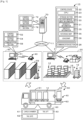
- Fig. 1 is a schematic explanatory view illustrating an example of delivery system 10.
- Fig. 2 is an explanatory view illustrating an example of logistics center 20.
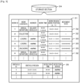
- Fig. 3 is an explanatory view illustrating an example of schedule information 31 and obstacle information 35 which are stored in storage section 24.
- Fig. 4 is an explanatory view illustrating an example of reference map 36 stored in storage section 24.
- Fig. 5 is an explanatory view illustrating an example of automatic movement device 40.
- Fig. 6 is an explanatory view of automatic movement device 40 connected to carriage 12
- Fig. 6A is a plan view
- Fig. 6B is a front view.
- Delivery system 10 is a system having an automatic movement device configured to automatically move an article inside a specific space, and to perform processing of delivering an article.
- delivery system 10 will be described by way of example in which the article is transported by using carriage 12, the present invention is not particularly limited to this, and carriage 12 may be omitted or other components may be used.
- the "article” is not particularly limited as long as anything is delivered, and for example, examples of the “article” include machines, devices, industrial products including units and components of devices, generally used daily consumer products, foods, and fresh products.
- examples of a "delivery source” and a "delivery destination” include a logistics center for collecting and delivering the article, a warehouse for storing the article, and a shop for selling the article.
- examples of the "specific space” include a cargo chamber of a mobile transporter for delivering the article and work elevator 18 (refer to Fig. 2 ), in addition to the above-described delivery source and delivery destination.
- the mobile transporter include a vehicle such as delivery vehicle 60 and a train, a ship, and an aircraft.
- delivery system 10 for delivering commodities such as consumer products and fresh products by using delivery vehicle 60 from logistics center 20 serving as the delivery source to shop 50 serving as the delivery destination will be mainly described.
- the "specific space” is logistics center 20.
- work elevator 18 (refer to Fig. 2 ) is used.
- a left-right direction, a front-rear direction, and an up-down direction will be described as illustrated in each drawing.
- Carriage 12 includes loading section 13 and caster 14.
- Loading section 13 is a plate-shaped member for loading the article.
- Caster 14 has wheels for causing carriage 12 to travel, and is disposed on a lower surface side of loading section 13.
- Carriage 12 may be a basket carriage.
- Logistics center 20 is a place for collecting the articles and delivering the articles to shops 50 or other logistics centers 20 in various locations.
- Logistics center 20 has one or more automatic movement devices 40, and can automatically move carriage 12.
- logistics center 20 uses a specific region on a floor surface as a collection region corresponding to the delivery destination.
- a worker or an arm robot (not illustrated) carries out work for loading the article on carriage 12 corresponding to the delivery destination.
- logistics center 20 includes movable region 15 in which automatic movement device 40 is movable and non-movable region 16 in which automatic movement device 40 is not movable.
- non-movable region 16 includes a structure such as a column which nothing can physically enter, and a collection region of carriage 12.
- logistics center 20 has doorway 17 and work elevator 18.
- Doorway 17 is a boundary that communicates with the outside, but automatic movement device 40 cannot basically enter doorway 17.
- Doorway 17 is an opening portion through which delivery vehicle 60 is laid down to load and unload the articles, or in which work elevator 18 is disposed to enable the articles to move to another floor.
- Automatic movement device 40 carries out work for collecting, loading, and unloading carriage 12 for which a delivery destination is specified.
- Delivery vehicle 60 loads carriage 12 in cargo chamber 61 in logistics center 20, delivers the articles to the delivery destination, and returns empty carriage 12 to logistics center 20.
- Shop 50 displays and sells the delivered articles.
- Shop 50 has one or more automatic movement devices 40, and can automatically move carriage 12.
- Shop 50 has display shelf 59 on which the articles are displayed, and a worker displays the articles on the display shelf.
- delivery system 10 is configured to include logistics PC 21, shop PC 51, automatic movement device 40, and management server 70.
- Logistics PC 21 is disposed in logistics center 20, and performs commodity management in logistics center 20.
- Logistics PC 21 includes control device 22, storage section 24, and communication section 28.
- Control device 22 has CPU 23, and controls the whole device.
- Storage section 24 stores various application programs and various data files.
- Communication section 28 communicates with an external device such as automatic movement device 40.
- Communication section 28 exchanges information with management server 70 or shop PC 51 via network 11.
- storage section 24 stores delivery management information 30, schedule information 31, obstacle information 35, reference map 36, and usage map 38.
- delivery management information 30 includes delivery information in which the delivery destination and the article are associated with each other, correspondence information in which carriage 12 on which the article is loaded and the article are associated with each other.
- schedule information 31 includes information on a work schedule in which a work content, a worker, a work time, a work region, a work position, and a movement path of automatic movement device 40 are associated with each other.
- Schedule information 31 includes change information 32 and operation information 33.
- Change information 32 is information including a change region in which a movable region of automatic movement device 40 is changed in a specific space and a change time at which the region is changed.
- change information 32 includes information on a region where carriages 12 are collected in a specific delivery destination and a time at which the region is set, and information on a time at which delivery vehicle 60 arrives at predetermined doorway region 37 and a time at which delivery vehicle 60 departs from predetermined doorway region 37.
- Operation information 33 includes an operation time at which automatic movement device 40 starts operating, a position of a movement source, a position of a movement destination of the article, and a movement path thereof.
- Obstacle information 35 includes information on a position or a size of an obstacle existing inside logistics center 20 and obstructing the movement of automatic movement device 40, and additionally includes information on a device or a time used when the obstacle is detected. Obstacle information 35 is sequentially updated by automatic movement device 40 moving on a floor. The information on the obstacle included in obstacle information 35 is thereafter deleted when the obstacle disappears.
- Reference map 36 is a basic map of a region of automatic movement device 40 relating to logistics center 20. As illustrated in Fig. 4 , reference map 36 includes floor map 36a of logistics center 20 illustrated in Fig. 2 , floor map 36b of work elevator 18, and floor map 36c of the cargo chamber of delivery vehicle 60.
- Floor maps 36a to 36c include doorway region 37 through which outward passage is allowable.
- Floor maps 36b and 36c are movement regions that are relatively moved to, coupled to, and separated from floor map 36a.
- Usage map 38 is a map used when automatic movement device 40 moves in logistics center 20.
- Usage map 38 is a map obtained as follows in reference map 36; a current state where automatic movement device 40 coupled to newly prepared non-movable region 16 or the movement region is currently movable is reflected on reference map 36 (refer to Figs. 8 and 9 to be described later). Usage map 38 is prepared by logistics PC 21, is transmitted to automatic movement device 40, and is used by automatic movement device 40.
- Shop PC 51 is disposed in shop 50, and performs commodity management in shop 50.
- Shop PC 51 includes control section 52, storage section 54, and communication section 58.
- Control section 52 has a CPU, and controls the whole device.
- Storage section 54 stores various application programs and various data files.
- Communication section 58 communicates with an external device such as automatic movement device 40.
- Communication section 58 exchanges information with management server 70 and logistics PC 21 via network 11.
- Storage section 54 stores commodity management information in which the article and the display shelf are associated with each other, schedule information, and a reference map or a usage map used by automatic movement device 40.
- Storage section 54 may include the same contents as schedule information 31, obstacle information 35, reference map 36, and usage map 38 which are stored in logistics PC 21.
- Automatic movement device 40 is a vehicle that automatically moves carriage 12. Automatic movement device 40 enters a space formed with caster 14 on a lower surface side of loading section 13 of carriage 12, connects loading section 13 to carriage 12 by lifting loading section 13 from below with lift portion 44, and moves carriage 12. Automatic movement device 40 may be an automatic guided vehicle (AGV) that moves on a predetermined traveling road, or may be an autonomous mobile robot (AMR) that moves on a free route by sensing surroundings.
- AMR autonomous mobile robot
- automatic movement device 40 includes movement control section 41, storage section 42, vehicle body part 43, lift portion 44, mecanum wheel 45, movement driving section 46, detection sensor 47, and communication section 48.
- Movement control section 41 is a controller for controlling the whole device of automatic movement device 40. Movement control section 41 outputs a control signal to lift portion 44, movement driving section 46, or communication section 48, and inputs an input signal from detection sensor 47 and communication section 48. Movement control section 41 recognizes a movement direction, a movement distance, a current position of automatic movement device 40, based on a drive state of movement driving section 46.
- Storage section 42 stores various application programs and various data files. For example, storage section 42 stores schedule information 31 for moving carriage 12, and usage map 38 of logistics center 20.
- the schedule information and the map data are acquired by communication from logistics PC 21.
- Lift portion 44 is connected to carriage 12 by lifting and pushing up a lower surface of loading section 13 with respect to vehicle body part 43 of automatic movement device 40 (refer to Fig. 6 ).
- Mecanum wheel 45 has a structure in which multiple rollers pivotally supported to be freely rotatable at an inclination angle of 45° with respect to a vehicle axle are disposed on a grounding surface side.
- Automatic movement device 40 includes four mecanum wheel 45, and is configured to be capable of moving automatic movement device 40 in all directions, super-fuzzy terrain turning, fuzzy terrain turning, slow turning by independently rotating respective mecanum wheels 45 in a front direction or a rear direction.
- Movement driving section 46 is a motor connected to respective mecanum wheels 45 and rotationally driving connected mecanum wheel 45 to drive automatic movement device 40 to travel.
- Detection sensor 47 detects an object existing around automatic movement device 40 or a distance from the object. For example, detection sensor 47 detects the existence of the object or the distance from the object by irradiating the surroundings with light such as a laser, or a sound wave and detecting a reflected wave.
- Movement control section 41 controls automatic movement device 40 to move or stop, based on information from detection sensor 47.
- Communication section 48 wirelessly exchanges information with an external device such as logistics PC 21. Movement control section 41 moves to a position of carriage 12 based on a command obtained from logistics PC 21 via communication section 48, is connected to carriage 12, and thereafter, moves carriage 12 to a movement destination position along a set movement path.
- Delivery vehicle 60 is a vehicle that loads and delivers one or more carriages 12. As illustrated in Fig. 1 , delivery vehicle 60 includes cargo chamber 61, tail gate 62, and tail lift 63.
- Cargo chamber 61 is a specific space in which carriages 12 are collected.
- Tail gate 62 is provided in a rear part of a vehicle, and opens and closes cargo chamber 61 by a closing door.
- Tail lift 63 loads carriage 12 or a worker on a work table which is horizontal when the closing door is opened, and moves the work table up and down between a floor surface of cargo chamber 61 and a traveling surface of delivery vehicle 60.
- tail gate 62 and tail lift 63 can be mechanically operated by a motor or a hydraulic pressure.
- carriage 12 is delivered by delivery vehicle 60 of the truck, but a configuration is not particularly limited to this, and may be delivered by a mobile transporter such as a train, a ship, and an aircraft.
- Management server 70 is a device that manages delivery system 10.
- Management server 70 includes control section 72, storage section 74, and communication section 78.
- Control section 72 has a CPU, and controls the whole device.
- Storage section 74 stores various application programs and various data files.
- Storage section 74 stores delivery management information used for managing the delivery of the articles, carriage information for managing carriage 12 used in logistics center 20 or shop 50, and a reference map of logistics center 20 or shop 50.
- the delivery management information includes delivery information in which the delivery destination and the article are associated with each other, correspondence information in which carriage 12 on which the article is loaded and the article are associated with each other.
- the schedule information includes information on a work schedule in which a work content, a worker, a work time, a work region, a work position, and a movement path of automatic movement device 40 are associated with each other.
- Communication section 78 exchanges information with an external device such as logistics PC 21 and shop PC 51 via network 11.
- FIG. 7 is a flowchart illustrating an example of a usage map preparation and transmission processing routine performed by control device 22 of logistics PC 21.
- the routine is stored in storage section 24 of control device 22, and is performed from when logistics center 20 starts work.
- CPU 23 acquires schedule information 31 from management server 70, reads and acquires obstacle information 35 from storage section 24 (S100), and determines whether a current time is a time at which the region is changed, based on schedule information 31 (S110).
- the "time at which the region is changed” may be a time based on the time at which the region is changed, or may be before a predetermined time in a change time (for example, 2 minutes before, 5 minutes before, or 10 minutes before), or may be just the change time, or after a predetermined time after the change time elapses (for example, 1 minute after or 2 minutes after).
- the "region is changed” includes a case where movable region 15 is changed to non-movable region 16 within a predetermined range, and a case where non-movable region 16 is changed to movable region 15.
- the examples include a case where a collection region of carriage 12 to a specific delivery destination is set on the floor and a case where the collection region is canceled from the floor.
- CPU 23 determines whether the current time is an operation time at which any one of automatic movement devices 40 starts operating, based on schedule information 31 (S120).
- the "operation time at which the operation starts” may be a time based on an operation start time, or for example, may be before a predetermined time in the operation time (for example, 2 minutes before, 5 minutes before, or 10 minutes before), or may be just the operation time, or after a predetermined time after the operation time elapses (for example, 1 minute after or 2 minutes after).
- CPU 23 determines whether there is a change in movable region 15 at the current time (S130).
- CPU 23 prepares usage map 38 in which changed movable region 15 is reflected on reference map 36 (S140).
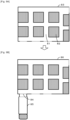
- Fig. 8 is an explanatory view of preparing new usage map 83 from usage map 80
- Fig. 8A is an explanatory view of usage map 80
- Fig. 8B is an explanatory view of usage map 83.
- CPU 23 reflects the current situation on floor map 36a, and prepares usage map 80 including movable region 81 and non-movable region 82 ( Fig. 8A ).
- CPU 23 reflects the current situation, and prepares usage map 83 including new non-movable region 82 ( Fig. 8B ).
- CPU 23 may reflect all of the current situations on reference map 36 each time, or may reflect a change on previous usage map 80 including reference map 36.
- CPU 23 determines whether the movement region is changed (S150).
- the "movement region is changed” includes any one of whether the movement region (for example, delivery vehicle 60) is coupled to logistics center 20 and whether the movement region is separated from logistics center 20.
- CPU 23 prepares usage map 38 by reflecting the movement region on doorway region 37 (S160).
- Fig. 9 is an explanatory view for preparing usage map 86 by coupling movement region 85 to usage map 83
- Fig. 9A is an explanatory view of usage map 83
- Fig. 9B is an explanatory view of usage map 86.
- CPU 23 reflects the current situation on floor map 36a, and prepares usage map 83 including movable region 81 and non-movable region 82 ( Fig. 9A ).
- CPU 23 prepares usage map 86 in which movement region 85 is coupled to doorway region 84 by reflecting the current situation ( Fig. 9B ).
- CPU 23 determines that delivery vehicle 60 is in contact with doorway 17 determined in advance in schedule information 31, CPU 23 couples movement region 85 to predetermined doorway region 84 in accordance with the determination.
- CPU 23 may reflect all of the current situations on reference map 36 each time, or may reflect the change in previous usage map 83 including reference map 36.
- Fig. 10 is an explanatory view for preparing usage map 90 by coupling movement region 87 of work elevator 18
- Fig. 10A is an explanatory view of usage map 88
- Fig. 10B is an explanatory view of movement region 87
- Fig. 10C is an explanatory view of usage map 90.
- automatic movement device 40 is illustrated for convenience of description. When automatic movement device 40 waits for work elevator 18 in doorway region 89, CPU 23 prepares usage map 88 by coupling movement region 87 to doorway region 89 ( Fig. 10A ).
- Fig. 11 is an explanatory view for preparing usage map 92 by adding obstacle region 91.
- obstacle region 91 is added to usage map 86 ( Fig. 9 ). In this way, CPU 23 can provide usage map 92 closer to the current specific space by reflecting newly changed non-movable region 82, newly coupled movement region 85, and locally detected obstacle region 91.
- Logistics center 20B is configured to include an internal open space which delivery vehicle 60 enters.
- Fig. 12 is an explanatory view of an example of another logistics center 20B
- Fig. 12A is an explanatory view of logistics center 20B
- Fig. 12B is an explanatory view of usage map 80B.
- One or more region detection devices 29 for detecting positions of collected carriages 12 and delivery vehicle 60 are disposed in logistics center 20B.
- Region detection device 29 may be a non-contact sensor, or may be a camera.
- CPU 23 detects the positions of delivery vehicle 60 and collected carriages 12 by region detection device 29, reflects non-movable region 82B and movement region 85B on the floor map, and prepares usage map 80B.
- usage map 80B the movement into movement region 87B is available from only doorway region 84B. In this way, CPU 23 may prepare usage map 80B including movement region 85B inside reference map 36. CPU 23 can properly secure the movement of automatic movement device 40 by using usage map 80B.
- CPU 23 determines whether a report on an obstacle is acquired from any one of automatic movement devices 40 (S200). During the work on the floor, when detecting the existence of a new obstacle and a fact that the obstacle is removed, automatic movement device 40 transmits a report thereof to logistics PC 21. When receiving the report, CPU 23 updates obstacle information 35 (S210). After S210 or when the report on the obstacle is not received in S200, CPU 23 determines whether all of the works are completed (S220), and performs the processing subsequent to S100 when all of the works are not completed.
- CPU 23 prepares new usage map 38, and transmits usage map 38 to automatic movement device 40.
- the routine is completed.
- FIG. 13 is a flowchart illustrating an example of an automatic movement control processing routine performed by movement control section 41 of automatic movement device 40.
- the routine is stored in storage section 42, and is performed after automatic movement device 40 is activated.
- movement control section 41 acquires schedule information 31 of a host device from logistics PC 21 (S300), and waits until the current time reaches the operation time (S310).
- operation time S310
- movement control section 41 acquires usage map 38 transmitted from logistics PC 21 (S320), and performs a movement processing and predetermined work, based on schedule information 31 (S330).
- movement control section 41 moves to a movement source position of carriage 12, and moves carriage 12 to a movement destination position. In the predetermined work, connection and disconnection are performed by moving lift portion 44 up and down in a lower portion of carriage 12.
- movement control section 41 determines whether a new obstacle is detected by detection sensor 47 or an existing obstacle is not detected. When the new obstacle is detected or the existing obstacle is not detected, movement control section 41 transmits a report relating to the obstacle to logistics PC 21 (S350), and acquires another movement path from logistics PC 21 (S360). After S360 or when the new obstacle is not detected or the existing obstacle is detected in S340, movement control section 41 determines whether the work based on current schedule information 31 is completed (S370).
- movement control section 41 When the current work is not completed, movement control section 41 performs the processing subsequent to S320. Latest usage map 38 is transmitted from logistics PC 21 each time the current time reaches the change time, and movement control section 41 performs the movement processing by using latest usage map 38.
- movement control section 41 determines whether all of the works are completed (S380). When all of the works are not completed, movement control section 41 performs the processing subsequent to S300, and when all of the works are completed, movement control section 41 moves to a standby position (S390), and completes the routine. In this way, automatic movement device 40 moves carriage 12 while using latest usage map 38.
- logistics center 20, shop 50, work elevator 18, and cargo chamber 61 of the present embodiment correspond to a specific space
- carriage 12 corresponds to a carriage
- delivery system 10 corresponds to a delivery system
- control device 22 corresponds to a control device
- CPU 23 corresponds to a processing control section
- storage section 24 corresponds to a storage section
- schedule information 31 corresponds to schedule information
- change information 32 corresponds to change information
- operation information 33 corresponds to operation information
- reference map 36 and floor maps 36a to 36c correspond to reference maps
- usage maps 38, 80, 83, 86, 88, 90, and 92 correspond to usage maps.
- an example of the control method according to the present disclosure is also clarified by describing an operation of delivery system 10.
- Control device 22 of the present embodiment described above performs processing of preparing new usage map 38 used by automatic movement device 40 by adding a change to reference map 36 of the specific space, based on schedule information 31 including change information 32 including the change region in which movable region 15 of automatic movement device 40 is changed in the specific space and the change time at which the region is changed, and operation information 33 including the operation time at which automatic movement device 40 starts operating.
- schedule information 31 including change information 32 including the change region in which movable region 15 of automatic movement device 40 is changed in the specific space and the change time at which the region is changed
- operation information 33 including the operation time at which automatic movement device 40 starts operating.
- usage map 38 closer to the actual state can be prepared in advance by using schedule information 31 and considering a situation of the specific space. Therefore, in control device 22, the article can be more smoothly moved in accordance with a change in the situation of the specific space for moving the article.
- control device 22 derives an optimum movement path of automatic movement device 40 by using usage map 38, it is possible to provide an efficient movement path in advance
- control device 22 since control device 22 prepares usage map 38 by reflecting the change region included in schedule information on reference map 36, based on the change time included in schedule information 31, usage map 38 closer to the actual state can be prepared in accordance with the time at which the region is changed. In addition, since control device 22 transmits usage map 38 on which the change region is reflected to automatic movement device 40, based on the change time included in schedule information 31, automatic movement device 40 can use usage map 38 closer to the actual state in accordance with the change time of the specific space. Furthermore, since control device 22 prepares usage map 38 by reflecting the change region included in schedule information 31 on the reference map 38, based on the operation time included in schedule information 31, usage map 38 closer to the actual state can be prepared in accordance with the operation time of automatic movement device 40. Furthermore, since control device 22 transmits usage map 38 on which the change region is reflected to automatic movement device 40, based on the operation time included in schedule information 31, automatic movement device 40 can use usage map 38 closer to the actual state in accordance with the operation time of automatic movement device 40.
- control device 22 prepares usage map 38 by adding a change in movable region 15 of automatic movement device 40 to reference map 36, based on the acquired information on the obstacle.
- usage map 38 can be prepared by using the actual information recognized by autonomous movement device 40 itself or another device.
- control device 22 adds a change in movable region 15 by giving priority to the information on the obstacle which is acquired from automatic movement device 40 of a host device or another automatic movement device 40, compared to the information included in schedule information 31, usage map 38 closer to the actual situation can be prepared.
- control device 22 Since control device 22 performs processing of coupling the movement region moving relative to the specific space to reference map 36 and processing of separating the movement region from reference map 36, usage map 38 including a movable region or a non-movable region of automatic movement device 40 can be prepared by newly coupling or separating the movement region.
- control device 22 since the region of delivery vehicle 60 for delivering the article and the region of work elevator 18 on which automatic movement device 40 rides are included as the movement region, control device 22 can couple and separate the region to be added to or separated from the movable range region of automatic movement device 40.
- control device 22 since control device 22 performs processing of coupling the movement region to doorway region 37 set in reference map 36, the movement region can be coupled to a predetermined position, and the usage map to which the movement region is coupled can be smoothly prepared.
- control device 22 prepares new usage map 38, when the current time reaches the change time included in schedule information 31, and when the current time reaches the operation time included in schedule information 31, the configuration is not particularly limited to this, and control device 22 may prepare new usage map 38 when the current time reaches either the change time or the operation time.
- control device 22 transmits usage map 38 to automatic movement device 40, when the current time reaches the change time included in schedule information 31 and when the current time reaches the operation time included in schedule information 31, the configuration is not particularly limited to this, and usage map 38 may be transmitted to automatic movement device 40 when the current time reaches either the change time or the operation time. Even in control device 22 configured in this way, usage map 38 closer to the actual state can be prepared and transmitted in advance, and the article can be more smoothly moved in accordance with a change in the situation of the specific space for moving the article.
- control device 22 prepares usage map 38 by using the information on the object (obstacle) existing in the specific space, the configuration is not particularly limited to this, and the processing may be omitted.
- usage map 38 closer to the actual state can be prepared in advance by simplifying the processing.
- region detection device 29 (refer to Fig. 12 ) disposed inside the specific space may be used for detecting the obstacle.
- Fig. 14 is an explanatory view in a state where tail gate 62 is closed
- Fig. 14A is an explanatory view of logistics center
- Fig. 14B is an explanatory view of usage map 80 of logistics center
- Fig. 14C is an explanatory view of logistics center 20B
- Fig. 14D is an explanatory view of usage map 80B of logistics center 20B.
- movement control section 41 of automatic movement device 40 causes detection sensor 47 to detect that doorway region 84 of movement region 85 is closed.
- Movement control section 41 transmits information indicating a non-movable state to logistics PC 21.
- CPU 23 of control device 22 acquires a signal indicating that the doorway of movement region 85 is closed from automatic movement device 40, CPU 23 displays and outputs information indicating that tail gate 62 is closed. A worker who confirms the information advises delivery vehicle 60 to open tail gate 62.
- Control device 22 can cope with the situation where the movement device 40 can enter added movement region 85 by locally detecting automatic movement device 40. Control device 22 can also cope with the same situation in logistics center 20B.
- control device 22 may cope with the situation as follows when delivery vehicle 60 is connected to doorway 17 in a deviated manner.
- Movement control section 41 of automatic movement device 40 can causes detection sensor 47 to detect that movement region 85 is connected in the deviated manner.
- movement control section 41 calculates a deviation amount of delivery vehicle 60 by using a detected value of detection sensor 47, and transmits the deviation amount to logistics PC 21.
- Control device 22 of logistics PC 21 uses the deviation amount, couples the deviation amount to reference map 36 in a state where the movement region is shifted, and prepares usage map 38.
- Control device 22 transmits newly prepared usage map 38 to automatic movement device 40, and performs processing of moving automatic movement device 40 by using new usage map 38.
- automatic movement device 40 can properly move even when delivery vehicle 60 deviates.
- the present disclosure is highly meaningful when applied to logistics center 20B ( Fig. 12 ) having an open space in which delivery vehicle 60 is likely to deviate.
- control device 22 may cope with the situation by automatic movement device 40 performing processing of shifting a position of the host device.
- usage map 38 is prepared by adding the change between movable region 15 and non-movable region 16 inside the specific space when a change is added to reference map 36
- the configuration is not particularly limited to this, and the processing may be omitted.
- Usage map 38 may be prepared by either changing usage map 38 inside the specific space or coupling and separating usage map 38 inside the specific space.
- automatic movement device 40 may be an automatic guided vehicle (AGV) that moves on a predetermined traveling road.
- AGV automatic guided vehicle
- carriage 12 can also be automatically moved, and a workload of a worker can be further reduced.
- detection sensor 47 may have a simpler configuration, or may be omitted.
- the configuration is not particularly limited to this, and the preparation of usage map 38 may be applied to shop 50.
- control device 22 of logistics PC 21 prepares the usage map
- the configuration is not particularly limited to this, and any one or more of control section 72 of management server 70, control section 52 of shop PC 51, movement control section 41 of automatic movement device 40 may prepare usage map 38. That is, as long as prepared usage map 38 can be directly or indirectly transmitted to automatic movement device 40, any device may have a function of the control device according to the present disclosure.
- automatic movement device 40 includes mecanum wheel 45 and is movable in an endless manner
- the configuration is not particularly limited to this as long as automatic movement device 40 has a configuration capable of traveling.
- Automatic movement device 40 may have a normal wheel.
- automatic movement device 40 may include four wheels, three wheels, or may include two main wheels and one or more sub wheels.
- delivery system 10 or control device 22
- the configuration is not particularly limited to this, and may be a control method used in a delivery system.
- the processing control section may prepare the usage map by reflecting the change region included in the schedule information on the reference map, based on the change time included in the schedule information.
- the usage map closer to the actual state can be prepared in accordance with the time at which the region is changed.
- the "reflected on the reference map, based on the change time” may mean reflected on the reference map before a predetermined time in the change time (for example, 2 minutes before, 5 minutes before, or 10 minutes before), may mean reflected on the reference map at the change time, or may be reflected on the reference map after the current time reaches the change time.
- control device may transmit the usage map on which the change region is reflected to the automatic movement device, based on the change time included in the schedule information.
- the automatic movement device can use the usage map closer to the actual state in accordance with the change time in the specific space.
- the "transmitting the usage map, based on the change time” may mean transmitting the usage map before a predetermined time in the change time, at the change time, or after the current time reaches the change time.
- the processing control section may prepare the usage map by reflecting the change region included in the schedule information on the reference map, based on the operation time included in the schedule information.
- the usage map closer to the actual state can be prepared in accordance with the operation time of the automatic movement device.
- the "reflected on the reference map, based on the operation time” may mean reflected on the reference map before a predetermined time in the operation time (for example, 2 minutes before, 5 minutes before, or 10 minutes before), may mean reflected on the reference map at the operation time, or may mean reflected on the reference map after the current time reaches the operation time.
- control device may transmit a usage map reflecting the change region to the automatic movement device based on an operation time included in the schedule information.
- the automatic movement device can use the usage map closer to the actual state in accordance with the operation time of the automatic movement device.
- the "transmitting the usage map, based on the operation time” may mean transmitting the usage map before a predetermined time in the operation time, at the operation time, or after the current time reaches the operation time.
- the processing control section when the processing control section acquires the information on the object existing in the specific space from the operating automatic movement device or from another device excluding the operating automatic movement device, the processing control section may prepare the usage map by adding the change in the movable region of the automatic movement device to the reference map, based on the acquired information on the object.
- the usage map can be prepared by using the actual information on the position and the size of the object recognized by the autonomous movement device itself or another device.
- examples of another device excluding the automatic movement device include another automatic movement device and a detection device disposed inside the specific space.
- the processing control section may add the change in the movable region of the automatic movement device to the reference map by giving priority to the information on the object existing in the specific space which is acquired from the operating automatic movement device or from another device excluding the operating automatic movement device, in comparison to the information included in the schedule information.
- the usage map closer to the actual state can be prepared.
- the processing control section may perform at least one of processing of coupling the movement region moving relative to the specific space to the reference map, and processing of separating the movement region from the reference map.
- the usage map including the movable region or the non-movable region of the automatic movement device can be prepared.
- the movement region may include at least one of the region of the delivery vehicle for delivering the article and the region of the work elevator on which the automatic movement device rides.
- the control device can couple and separate the region to be added to or separated from the movable range region of the automatic movement device such as the delivery vehicle and the work elevator.
- the processing control section may perform processing of coupling the movement region to the doorway region set in the reference map.
- the control device since the movement region can be coupled to a predetermined position, the usage map to which the movement region is coupled can be smoothly prepared.
- the processing control section may output the information indicating that the doorway of the movement region is closed, when a signal indicating that the doorway of the movement region is closed is acquired from the automatic movement device.
- the control device can cope with a situation where the automatic movement device can enter added movement region.
- the processing control section may output a command to open the doorway to the device corresponding to the movement region.
- the delivery system for delivering the article including the management device including the control device according to any one of the above-described configurations, and the automatic movement device configured to automatically move the article inside the specific space, in which the automatic movement device acquires the usage map prepared by the control device from the control device, and uses the usage map for the movement of the article. Since the delivery system includes any one of the control devices described above, it is possible to obtain an advantageous effect corresponding to the adopted aspect.
- control method used in the delivery system having the automatic movement device that automatically moves the article inside the specific space and delivering the article
- the control method including a step of performing processing of preparing the usage map used by the automatic movement device by adding a change to the reference map of the specific space, based on the schedule information including at least one of the change information including the change region in which the movable region of the automatic movement device is changed in the specific space and the change time at which the region is changed, and the operation information including the operation time at which the automatic movement device starts operating.
- the usage map closer to the actual state can be prepared in advance by using the schedule information and considering the situation of the specific space. Therefore, the control device can more smoothly move the article in accordance with a change in the situation of the specific space for moving the article.
- various aspects of the above-described control device may be adopted, or steps for realizing each function of the above-described control device may be added.
- the carriage aligning device, the automatic movement device, the delivery system, and the control method according to the present disclosure can be used in a technical field of a commodity logistics system for delivering commodities.
Landscapes
- Engineering & Computer Science (AREA)
- Business, Economics & Management (AREA)
- Mechanical Engineering (AREA)
- Economics (AREA)
- Theoretical Computer Science (AREA)
- General Physics & Mathematics (AREA)
- Physics & Mathematics (AREA)
- General Business, Economics & Management (AREA)
- Tourism & Hospitality (AREA)
- Development Economics (AREA)
- General Engineering & Computer Science (AREA)
- Entrepreneurship & Innovation (AREA)
- Human Resources & Organizations (AREA)
- Software Systems (AREA)
- Quality & Reliability (AREA)
- Marketing (AREA)
- Strategic Management (AREA)
- Operations Research (AREA)
- Computer Security & Cryptography (AREA)
- Aviation & Aerospace Engineering (AREA)
- Control Of Position, Course, Altitude, Or Attitude Of Moving Bodies (AREA)
- Warehouses Or Storage Devices (AREA)
Abstract
Description
- The present specification discloses a control device, a delivery system, and a control method.
- In the related art, a technique has been proposed in a system that automatically moves an article as follows; when one or more robotic devices carry out one or more tasks, in a case where data for developing the task is received, the task is carried out by updating a map, based on the received data (for example, refer to Patent Literature 1). In this system, the article can be moved by using the updated map. In addition, as a control device for preparing the map, a device for setting a connecting point for connecting partial maps by a user's input has been proposed (for example, refer to Patent Literature 2). This device can flexibly cope with a partial layout change.
-
- Patent Literature 1:
U.S. Patent Publication No. 2016/129592 - Patent Literature 2:
JP-A-2010-92147 - However, in the system disclosed in
Patent Literature 1, when the data for updating the map cannot be obtained, the map may not be updated in some cases. In addition, in the device disclosed inPatent Literature 2, it is necessary for a user to designate the connecting point when connecting the maps. In this way, a delivery system needs to be more smoothly operated when the article is moved. - The present disclosure is made to solve the above-described problems, and a principal object according to the present disclosure is to provide a control device, a delivery system, and a control method which can more smoothly move an article in accordance with a change in situations of a specific space for moving the article.
- The present disclosure adopts the following means to achieve the above-described principal object.
- According to the present specification, there is provided a control device used in a delivery system having an automatic movement device that automatically moves an article inside a specific space and delivering the article, the control device including a storage section configured to store schedule information including at least one of change information including a change region in which a movable region of the automatic movement device is changed in the specific space and a change time at which the region is changed, and operation information including an operation time at which the automatic movement device starts operating; and a processing control section configured to perform processing of preparing a usage map used by the automatic movement device by adding a change to a reference map of the specific space, based on the schedule information.
- The control device performs processing of preparing a new usage map used by the automatic movement device by adding the change to the reference map of the specific space, based on the schedule information including at least one of the change information including the change region in which the movable region of the automatic movement device is changed in the specific space and the change time at which the region is changed, and the operation information including the operation time at which the automatic movement device starts operating. The control device can prepare in advance the usage map closer to an actual state by using the schedule information and considering a situation of the specific space. Therefore, the control device can more smoothly move the article in accordance with a change in the situation of the specific space for moving the article. Here, the "article" is not particularly limited as long as anything is delivered, and for example, examples of the "article" include industrial products including units and components of machines or devices, general consumer products, foods, and fresh products. In addition, for example, examples of the "specific space" include a logistics center or a warehouse where the articles are collected, a shop, and a cargo chamber of a mobile transporter for delivering the articles. Examples of the mobile transporter include an elevator in addition to a vehicle such as an automobile and a train, a ship, and an aircraft. In addition, the "automatic movement device" may be an automatic guided vehicle (AGV) that moves on a predetermined traveling road, or may be an autonomous mobile robot (AMR) that moves on a free route by sensing surroundings.
-
- [
Fig. 1] Fig. 1 is a schematic explanatory view illustrating an example ofdelivery system 10. - [
Fig. 2] Fig. 2 is an explanatory view illustrating an example oflogistics center 20. - [
Fig. 3] Fig. 3 is an explanatory view illustrating an example of information stored instorage section 24. - [
Fig. 4] Fig. 4 is an explanatory view illustrating an example ofreference map 36. - [
Fig. 5] Fig. 5 is an explanatory view illustrating an example ofautomatic movement device 40. - [
Fig. 6] Fig. 6 is an explanatory view ofautomatic movement device 40 connected tocarriage 12. - [
Fig. 7] Fig. 7 is a flowchart illustrating an example of a usage map preparation and transmission processing routine. - [
Fig. 8] Fig. 8 is an explanatory view for preparingnew usage map 83 fromusage map 80. - [
Fig. 9] Fig. 9 is an explanatory view for preparingusage map 86 bycoupling movement region 85 tousage map 83. - [
Fig. 10] Fig. 10 is an explanatory view for preparingusage map 90 bycoupling movement region 87. - [
Fig. 11] Fig. 11 is an explanatory view for preparingusage map 92 by addingobstacle region 91. - [
Fig. 12] Fig. 12 is an explanatory view of an example of anotherlogistics center 20B. - [
Fig. 13] Fig. 13 is a flowchart illustrating an example of an automatic movement control processing routine. - [
Fig. 14] Fig. 14 is an explanatory view in a t state wheretail gate 62 is closed. - Embodiments according to the present disclosure will be described with reference to the drawings.
Fig. 1 is a schematic explanatory view illustrating an example ofdelivery system 10.Fig. 2 is an explanatory view illustrating an example oflogistics center 20.Fig. 3 is an explanatory view illustrating an example ofschedule information 31 andobstacle information 35 which are stored instorage section 24.Fig. 4 is an explanatory view illustrating an example ofreference map 36 stored instorage section 24.Fig. 5 is an explanatory view illustrating an example ofautomatic movement device 40.Fig. 6 is an explanatory view ofautomatic movement device 40 connected tocarriage 12,Fig. 6A is a plan view, andFig. 6B is a front view.Delivery system 10 is a system having an automatic movement device configured to automatically move an article inside a specific space, and to perform processing of delivering an article. Althoughdelivery system 10 will be described by way of example in which the article is transported by usingcarriage 12, the present invention is not particularly limited to this, andcarriage 12 may be omitted or other components may be used. Here, the "article" is not particularly limited as long as anything is delivered, and for example, examples of the "article" include machines, devices, industrial products including units and components of devices, generally used daily consumer products, foods, and fresh products. In addition, for example, examples of a "delivery source" and a "delivery destination" include a logistics center for collecting and delivering the article, a warehouse for storing the article, and a shop for selling the article. In addition, for example, examples of the "specific space" include a cargo chamber of a mobile transporter for delivering the article and work elevator 18 (refer toFig. 2 ), in addition to the above-described delivery source and delivery destination. Examples of the mobile transporter include a vehicle such asdelivery vehicle 60 and a train, a ship, and an aircraft. Here, for convenience of description,delivery system 10 for delivering commodities such as consumer products and fresh products by usingdelivery vehicle 60 fromlogistics center 20 serving as the delivery source to shop 50 serving as the delivery destination will be mainly described. In addition, the "specific space" islogistics center 20. In addition tocargo chamber 61 ofdelivery vehicle 60, work elevator 18 (refer toFig. 2 ) is used. In the present embodiment, a left-right direction, a front-rear direction, and an up-down direction will be described as illustrated in each drawing. - Carriage 12 includes
loading section 13 andcaster 14. Loadingsection 13 is a plate-shaped member for loading the article. Caster 14 has wheels for causingcarriage 12 to travel, and is disposed on a lower surface side ofloading section 13. Carriage 12 may be a basket carriage. -
Logistics center 20 is a place for collecting the articles and delivering the articles toshops 50 orother logistics centers 20 in various locations.Logistics center 20 has one or moreautomatic movement devices 40, and can automatically movecarriage 12. For example,logistics center 20 uses a specific region on a floor surface as a collection region corresponding to the delivery destination. Inlogistics center 20, a worker or an arm robot (not illustrated) carries out work for loading the article oncarriage 12 corresponding to the delivery destination. As illustrated inFig. 2 ,logistics center 20 includesmovable region 15 in whichautomatic movement device 40 is movable andnon-movable region 16 in whichautomatic movement device 40 is not movable. For example,non-movable region 16 includes a structure such as a column which nothing can physically enter, and a collection region ofcarriage 12. In addition,logistics center 20 hasdoorway 17 andwork elevator 18.Doorway 17 is a boundary that communicates with the outside, butautomatic movement device 40 cannot basically enterdoorway 17.Doorway 17 is an opening portion through whichdelivery vehicle 60 is laid down to load and unload the articles, or in which workelevator 18 is disposed to enable the articles to move to another floor.Automatic movement device 40 carries out work for collecting, loading, and unloadingcarriage 12 for which a delivery destination is specified.Delivery vehicle 60loads carriage 12 incargo chamber 61 inlogistics center 20, delivers the articles to the delivery destination, and returnsempty carriage 12 tologistics center 20. -
Shop 50 displays and sells the delivered articles.Shop 50 has one or moreautomatic movement devices 40, and can automatically movecarriage 12.Shop 50 hasdisplay shelf 59 on which the articles are displayed, and a worker displays the articles on the display shelf. - As illustrated in
Fig. 1 ,delivery system 10 is configured to includelogistics PC 21,shop PC 51,automatic movement device 40, andmanagement server 70.Logistics PC 21 is disposed inlogistics center 20, and performs commodity management inlogistics center 20.Logistics PC 21 includescontrol device 22,storage section 24, andcommunication section 28.Control device 22 hasCPU 23, and controls the whole device.Storage section 24 stores various application programs and various data files.Communication section 28 communicates with an external device such asautomatic movement device 40.Communication section 28 exchanges information withmanagement server 70 orshop PC 51 vianetwork 11. - As illustrated in
Figs. 1 and3 ,storage section 24 storesdelivery management information 30,schedule information 31,obstacle information 35,reference map 36, andusage map 38. For example,delivery management information 30 includes delivery information in which the delivery destination and the article are associated with each other, correspondence information in whichcarriage 12 on which the article is loaded and the article are associated with each other. As illustrated inFig. 3 ,schedule information 31 includes information on a work schedule in which a work content, a worker, a work time, a work region, a work position, and a movement path ofautomatic movement device 40 are associated with each other.Schedule information 31 includeschange information 32 andoperation information 33.Change information 32 is information including a change region in which a movable region ofautomatic movement device 40 is changed in a specific space and a change time at which the region is changed. For example, changeinformation 32 includes information on a region wherecarriages 12 are collected in a specific delivery destination and a time at which the region is set, and information on a time at whichdelivery vehicle 60 arrives atpredetermined doorway region 37 and a time at whichdelivery vehicle 60 departs frompredetermined doorway region 37.Operation information 33 includes an operation time at whichautomatic movement device 40 starts operating, a position of a movement source, a position of a movement destination of the article, and a movement path thereof.Obstacle information 35 includes information on a position or a size of an obstacle existing insidelogistics center 20 and obstructing the movement ofautomatic movement device 40, and additionally includes information on a device or a time used when the obstacle is detected.Obstacle information 35 is sequentially updated byautomatic movement device 40 moving on a floor. The information on the obstacle included inobstacle information 35 is thereafter deleted when the obstacle disappears. -
Reference map 36 is a basic map of a region ofautomatic movement device 40 relating tologistics center 20. As illustrated inFig. 4 ,reference map 36 includesfloor map 36a oflogistics center 20 illustrated inFig. 2 ,floor map 36b ofwork elevator 18, andfloor map 36c of the cargo chamber ofdelivery vehicle 60. Floor maps 36a to 36c includedoorway region 37 through which outward passage is allowable. Floor maps 36b and 36c are movement regions that are relatively moved to, coupled to, and separated fromfloor map 36a.Usage map 38 is a map used whenautomatic movement device 40 moves inlogistics center 20.Usage map 38 is a map obtained as follows inreference map 36; a current state whereautomatic movement device 40 coupled to newly preparednon-movable region 16 or the movement region is currently movable is reflected on reference map 36 (refer toFigs. 8 and9 to be described later).Usage map 38 is prepared bylogistics PC 21, is transmitted toautomatic movement device 40, and is used byautomatic movement device 40. -
Shop PC 51 is disposed inshop 50, and performs commodity management inshop 50.Shop PC 51 includescontrol section 52,storage section 54, andcommunication section 58.Control section 52 has a CPU, and controls the whole device.Storage section 54 stores various application programs and various data files.Communication section 58 communicates with an external device such asautomatic movement device 40.Communication section 58 exchanges information withmanagement server 70 andlogistics PC 21 vianetwork 11.Storage section 54 stores commodity management information in which the article and the display shelf are associated with each other, schedule information, and a reference map or a usage map used byautomatic movement device 40.Storage section 54 may include the same contents asschedule information 31,obstacle information 35,reference map 36, andusage map 38 which are stored inlogistics PC 21. -
Automatic movement device 40 is a vehicle that automatically movescarriage 12.Automatic movement device 40 enters a space formed withcaster 14 on a lower surface side ofloading section 13 ofcarriage 12, connects loadingsection 13 tocarriage 12 by liftingloading section 13 from below withlift portion 44, and movescarriage 12.Automatic movement device 40 may be an automatic guided vehicle (AGV) that moves on a predetermined traveling road, or may be an autonomous mobile robot (AMR) that moves on a free route by sensing surroundings. Here, anautomatic movement device 40 having a configuration of the AMR will be described. - As illustrated in
Fig. 5 ,automatic movement device 40 includesmovement control section 41,storage section 42,vehicle body part 43,lift portion 44,mecanum wheel 45,movement driving section 46,detection sensor 47, andcommunication section 48.Movement control section 41 is a controller for controlling the whole device ofautomatic movement device 40.Movement control section 41 outputs a control signal to liftportion 44,movement driving section 46, orcommunication section 48, and inputs an input signal fromdetection sensor 47 andcommunication section 48.Movement control section 41 recognizes a movement direction, a movement distance, a current position ofautomatic movement device 40, based on a drive state ofmovement driving section 46.Storage section 42 stores various application programs and various data files. For example,storage section 42 stores scheduleinformation 31 for movingcarriage 12, andusage map 38 oflogistics center 20. The schedule information and the map data are acquired by communication fromlogistics PC 21.Lift portion 44 is connected tocarriage 12 by lifting and pushing up a lower surface ofloading section 13 with respect tovehicle body part 43 of automatic movement device 40 (refer toFig. 6 ).Mecanum wheel 45 has a structure in which multiple rollers pivotally supported to be freely rotatable at an inclination angle of 45° with respect to a vehicle axle are disposed on a grounding surface side.Automatic movement device 40 includes fourmecanum wheel 45, and is configured to be capable of movingautomatic movement device 40 in all directions, super-fuzzy terrain turning, fuzzy terrain turning, slow turning by independently rotatingrespective mecanum wheels 45 in a front direction or a rear direction.Movement driving section 46 is a motor connected torespective mecanum wheels 45 and rotationally drivingconnected mecanum wheel 45 to driveautomatic movement device 40 to travel.Detection sensor 47 detects an object existing aroundautomatic movement device 40 or a distance from the object. For example,detection sensor 47 detects the existence of the object or the distance from the object by irradiating the surroundings with light such as a laser, or a sound wave and detecting a reflected wave.Movement control section 41 controlsautomatic movement device 40 to move or stop, based on information fromdetection sensor 47.Communication section 48 wirelessly exchanges information with an external device such aslogistics PC 21.Movement control section 41 moves to a position ofcarriage 12 based on a command obtained fromlogistics PC 21 viacommunication section 48, is connected tocarriage 12, and thereafter, movescarriage 12 to a movement destination position along a set movement path. -
Delivery vehicle 60 is a vehicle that loads and delivers one ormore carriages 12. As illustrated inFig. 1 ,delivery vehicle 60 includescargo chamber 61,tail gate 62, andtail lift 63.Cargo chamber 61 is a specific space in whichcarriages 12 are collected.Tail gate 62 is provided in a rear part of a vehicle, and opens and closescargo chamber 61 by a closing door.Tail lift 63loads carriage 12 or a worker on a work table which is horizontal when the closing door is opened, and moves the work table up and down between a floor surface ofcargo chamber 61 and a traveling surface ofdelivery vehicle 60. Indelivery vehicle 60,tail gate 62 andtail lift 63 can be mechanically operated by a motor or a hydraulic pressure. In the present embodiment,carriage 12 is delivered bydelivery vehicle 60 of the truck, but a configuration is not particularly limited to this, and may be delivered by a mobile transporter such as a train, a ship, and an aircraft. -
Management server 70 is a device that managesdelivery system 10.Management server 70 includescontrol section 72,storage section 74, andcommunication section 78.Control section 72 has a CPU, and controls the whole device.Storage section 74 stores various application programs and various data files.Storage section 74 stores delivery management information used for managing the delivery of the articles, carriage information for managingcarriage 12 used inlogistics center 20 orshop 50, and a reference map oflogistics center 20 orshop 50. The delivery management information includes delivery information in which the delivery destination and the article are associated with each other, correspondence information in whichcarriage 12 on which the article is loaded and the article are associated with each other. The schedule information includes information on a work schedule in which a work content, a worker, a work time, a work region, a work position, and a movement path ofautomatic movement device 40 are associated with each other.Communication section 78 exchanges information with an external device such aslogistics PC 21 andshop PC 51 vianetwork 11. - Next, in
delivery system 10 configured in this way, processing of updatingnon-movable region 16, coupling the movement region, and preparingusage map 38 on which the current state is reflected will be described.Fig. 7 is a flowchart illustrating an example of a usage map preparation and transmission processing routine performed bycontrol device 22 oflogistics PC 21. The routine is stored instorage section 24 ofcontrol device 22, and is performed from when logistics center 20 starts work. When the routine starts,CPU 23 acquiresschedule information 31 frommanagement server 70, reads and acquiresobstacle information 35 from storage section 24 (S100), and determines whether a current time is a time at which the region is changed, based on schedule information 31 (S110). Here, of example, the "time at which the region is changed" may be a time based on the time at which the region is changed, or may be before a predetermined time in a change time (for example, 2 minutes before, 5 minutes before, or 10 minutes before), or may be just the change time, or after a predetermined time after the change time elapses (for example, 1 minute after or 2 minutes after). In addition, the "region is changed" includes a case wheremovable region 15 is changed tonon-movable region 16 within a predetermined range, and a case wherenon-movable region 16 is changed tomovable region 15. For example, the examples include a case where a collection region ofcarriage 12 to a specific delivery destination is set on the floor and a case where the collection region is canceled from the floor. - When the current time is not the change time at which the region is changed,
CPU 23 determines whether the current time is an operation time at which any one ofautomatic movement devices 40 starts operating, based on schedule information 31 (S120). For example, the "operation time at which the operation starts" may be a time based on an operation start time, or for example, may be before a predetermined time in the operation time (for example, 2 minutes before, 5 minutes before, or 10 minutes before), or may be just the operation time, or after a predetermined time after the operation time elapses (for example, 1 minute after or 2 minutes after). When the current time is the operation time or when the current time is the change time in S110,CPU 23 determines whether there is a change inmovable region 15 at the current time (S130). When there is a change inmovable region 15,CPU 23 preparesusage map 38 in which changedmovable region 15 is reflected on reference map 36 (S140). - Here,
usage map 38 inlogistics center 20 whereautomatic movement device 40 carries out work will be described with reference to a specific example.Fig. 8 is an explanatory view of preparingnew usage map 83 fromusage map 80,Fig. 8A is an explanatory view ofusage map 80, andFig. 8B is an explanatory view ofusage map 83. For example, whenfloor map 36a illustrated inFig. 4 is set asreference map 36,CPU 23 reflects the current situation onfloor map 36a, and preparesusage map 80 includingmovable region 81 and non-movable region 82 (Fig. 8A ). Next, when the current time reaches the change time or the operation time,CPU 23 reflects the current situation, and preparesusage map 83 including new non-movable region 82 (Fig. 8B ). Here, when preparingusage map 83,CPU 23 may reflect all of the current situations onreference map 36 each time, or may reflect a change onprevious usage map 80 includingreference map 36. - On the other hand, after
S 140 or whenmovable region 15 is not changed in S130,CPU 23 determines whether the movement region is changed (S150). Here, the "movement region is changed" includes any one of whether the movement region (for example, delivery vehicle 60) is coupled tologistics center 20 and whether the movement region is separated fromlogistics center 20. When the movement region is changed,CPU 23 preparesusage map 38 by reflecting the movement region on doorway region 37 (S160). - Here,
usage map 38 oflogistics center 20 whereautomatic movement device 40 carries out work will be described with reference to a specific example.Fig. 9 is an explanatory view for preparingusage map 86 bycoupling movement region 85 tousage map 83,Fig. 9A is an explanatory view ofusage map 83, andFig. 9B is an explanatory view ofusage map 86. For example,CPU 23 reflects the current situation onfloor map 36a, and preparesusage map 83 includingmovable region 81 and non-movable region 82 (Fig. 9A ). Next, when the current time reaches the change time or the operation time,CPU 23 preparesusage map 86 in whichmovement region 85 is coupled todoorway region 84 by reflecting the current situation (Fig. 9B ). Here,CPU 23 determines thatdelivery vehicle 60 is in contact withdoorway 17 determined in advance inschedule information 31,CPU 23couples movement region 85 to predetermineddoorway region 84 in accordance with the determination. When preparingusage map 86,CPU 23 may reflect all of the current situations onreference map 36 each time, or may reflect the change inprevious usage map 83 includingreference map 36. - In addition, switching the maps of
work elevator 18 serving as the movement region will be described.Fig. 10 is an explanatory view for preparingusage map 90 bycoupling movement region 87 ofwork elevator 18,Fig. 10A is an explanatory view ofusage map 88,Fig. 10B is an explanatory view ofmovement region 87, andFig. 10C is an explanatory view ofusage map 90. InFig. 10 ,automatic movement device 40 is illustrated for convenience of description. Whenautomatic movement device 40 waits forwork elevator 18 indoorway region 89,CPU 23 preparesusage map 88 bycoupling movement region 87 to doorway region 89 (Fig. 10A ). Next, whenautomatic movement device 40 rides onwork elevator 18 and moves to another floor, the floor map oflogistics center 20 is separated as the movement region, andmovement region 87 is set as the floor map (Fig. 10B ). When arriving at another floor,usage map 90 is prepared by coupling the floor map of another floor tomovement region 87 in doorway region 89 (Fig. 10C ). In this way,CPU 23 appropriately movesautomatic movement device 40 by switching the maps inwork elevator 18. - After S160, based on information in
obstacle information 35,CPU 23 preparesusage map 38 on which an obstacle region is further reflected (S170), and derives an optimum movement path by using prepared usage map 38 (S180).CPU 23 may reflect the optimum movement path onschedule information 31. Subsequently,CPU 23 transmitsprepared usage map 38 and the derived movement path to automatic movement device 40 (S190).CPU 23 preparesusage map 38 on which the current situation is further reflected by giving priority to the information on the obstacle existing in the specific space. Inobstacle information 35, the information on the currently existing obstacle is sequentially updated.Fig. 11 is an explanatory view for preparingusage map 92 by addingobstacle region 91. InFig. 11 ,obstacle region 91 is added to usage map 86 (Fig. 9 ). In this way,CPU 23 can provideusage map 92 closer to the current specific space by reflecting newly changednon-movable region 82, newly coupledmovement region 85, and locally detectedobstacle region 91. - In addition, here, processing in another
logistics center 20B will be described.Logistics center 20B is configured to include an internal open space whichdelivery vehicle 60 enters.Fig. 12 is an explanatory view of an example of anotherlogistics center 20B,Fig. 12A is an explanatory view oflogistics center 20B, andFig. 12B is an explanatory view ofusage map 80B. One or moreregion detection devices 29 for detecting positions of collectedcarriages 12 anddelivery vehicle 60 are disposed inlogistics center 20B.Region detection device 29 may be a non-contact sensor, or may be a camera. Inlogistics center 20B,CPU 23 detects the positions ofdelivery vehicle 60 and collectedcarriages 12 byregion detection device 29, reflectsnon-movable region 82B andmovement region 85B on the floor map, and preparesusage map 80B. Inusage map 80B, the movement into movement region 87B is available fromonly doorway region 84B. In this way,CPU 23 may prepareusage map 80B includingmovement region 85B insidereference map 36.CPU 23 can properly secure the movement ofautomatic movement device 40 by usingusage map 80B. - After S190 or when the time is not the change time in S110 and is not the operation time in S120,
CPU 23 determines whether a report on an obstacle is acquired from any one of automatic movement devices 40 (S200). During the work on the floor, when detecting the existence of a new obstacle and a fact that the obstacle is removed,automatic movement device 40 transmits a report thereof tologistics PC 21. When receiving the report,CPU 23 updates obstacle information 35 (S210). After S210 or when the report on the obstacle is not received in S200,CPU 23 determines whether all of the works are completed (S220), and performs the processing subsequent to S100 when all of the works are not completed. That is, based onschedule information 31, when the times reach the change time and the operation time,CPU 23 preparesnew usage map 38, and transmitsusage map 38 toautomatic movement device 40. On the other hand, when all of the works are completed in S220, the routine is completed. - Next, processing performed by
automatic movement device 40 to movecarriage 12 inlogistics center 20 will be described.Fig. 13 is a flowchart illustrating an example of an automatic movement control processing routine performed bymovement control section 41 ofautomatic movement device 40. The routine is stored instorage section 42, and is performed afterautomatic movement device 40 is activated. When the routine starts,movement control section 41 acquiresschedule information 31 of a host device from logistics PC 21 (S300), and waits until the current time reaches the operation time (S310). When the current time reaches the operation time,movement control section 41 acquiresusage map 38 transmitted from logistics PC 21 (S320), and performs a movement processing and predetermined work, based on schedule information 31 (S330). In the movement processing, for example,movement control section 41 moves to a movement source position ofcarriage 12, and movescarriage 12 to a movement destination position. In the predetermined work, connection and disconnection are performed by movinglift portion 44 up and down in a lower portion ofcarriage 12. In S340, while the processing in S330 is continued,movement control section 41 determines whether a new obstacle is detected bydetection sensor 47 or an existing obstacle is not detected. When the new obstacle is detected or the existing obstacle is not detected,movement control section 41 transmits a report relating to the obstacle to logistics PC 21 (S350), and acquires another movement path from logistics PC 21 (S360). After S360 or when the new obstacle is not detected or the existing obstacle is detected in S340,movement control section 41 determines whether the work based oncurrent schedule information 31 is completed (S370). When the current work is not completed,movement control section 41 performs the processing subsequent to S320.Latest usage map 38 is transmitted fromlogistics PC 21 each time the current time reaches the change time, andmovement control section 41 performs the movement processing by usinglatest usage map 38. On the other hand, when the current work is completed in S370,movement control section 41 determines whether all of the works are completed (S380). When all of the works are not completed,movement control section 41 performs the processing subsequent to S300, and when all of the works are completed,movement control section 41 moves to a standby position (S390), and completes the routine. In this way,automatic movement device 40moves carriage 12 while usinglatest usage map 38. - Here, a correspondence between configuration elements of the present embodiment and configuration elements according to the present disclosure will be clarified.
Logistics center 20,shop 50,work elevator 18, andcargo chamber 61 of the present embodiment correspond to a specific space,carriage 12 corresponds to a carriage, anddelivery system 10 corresponds to a delivery system. In addition,control device 22 corresponds to a control device,CPU 23 corresponds to a processing control section, andstorage section 24 corresponds to a storage section. In addition,schedule information 31 corresponds to schedule information, changeinformation 32 corresponds to change information,operation information 33 corresponds to operation information,reference map 36 andfloor maps 36a to 36c correspond to reference maps, andusage maps delivery system 10. -
Control device 22 of the present embodiment described above performs processing of preparingnew usage map 38 used byautomatic movement device 40 by adding a change to referencemap 36 of the specific space, based onschedule information 31 includingchange information 32 including the change region in whichmovable region 15 ofautomatic movement device 40 is changed in the specific space and the change time at which the region is changed, andoperation information 33 including the operation time at whichautomatic movement device 40 starts operating. Incontrol device 22,usage map 38 closer to the actual state can be prepared in advance by usingschedule information 31 and considering a situation of the specific space. Therefore, incontrol device 22, the article can be more smoothly moved in accordance with a change in the situation of the specific space for moving the article. In addition, sincecontrol device 22 derives an optimum movement path ofautomatic movement device 40 by usingusage map 38, it is possible to provide an efficient movement path in advance. - In addition, since
control device 22 preparesusage map 38 by reflecting the change region included in schedule information onreference map 36, based on the change time included inschedule information 31,usage map 38 closer to the actual state can be prepared in accordance with the time at which the region is changed. In addition, sincecontrol device 22 transmitsusage map 38 on which the change region is reflected toautomatic movement device 40, based on the change time included inschedule information 31,automatic movement device 40 can useusage map 38 closer to the actual state in accordance with the change time of the specific space. Furthermore, sincecontrol device 22 preparesusage map 38 by reflecting the change region included inschedule information 31 on thereference map 38, based on the operation time included inschedule information 31,usage map 38 closer to the actual state can be prepared in accordance with the operation time ofautomatic movement device 40. Furthermore, sincecontrol device 22 transmitsusage map 38 on which the change region is reflected toautomatic movement device 40, based on the operation time included inschedule information 31,automatic movement device 40 can useusage map 38 closer to the actual state in accordance with the operation time ofautomatic movement device 40. - Furthermore, when the information on the object (obstacle) existing in the specific space is acquired from operated
automatic movement device 40 or another operatedautomatic movement device 40,control device 22 preparesusage map 38 by adding a change inmovable region 15 ofautomatic movement device 40 toreference map 36, based on the acquired information on the obstacle. Incontrol device 22,usage map 38 can be prepared by using the actual information recognized byautonomous movement device 40 itself or another device. Furthermore, sincecontrol device 22 adds a change inmovable region 15 by giving priority to the information on the obstacle which is acquired fromautomatic movement device 40 of a host device or anotherautomatic movement device 40, compared to the information included inschedule information 31,usage map 38 closer to the actual situation can be prepared. Sincecontrol device 22 performs processing of coupling the movement region moving relative to the specific space to referencemap 36 and processing of separating the movement region fromreference map 36,usage map 38 including a movable region or a non-movable region ofautomatic movement device 40 can be prepared by newly coupling or separating the movement region. In addition, since the region ofdelivery vehicle 60 for delivering the article and the region ofwork elevator 18 on whichautomatic movement device 40 rides are included as the movement region,control device 22 can couple and separate the region to be added to or separated from the movable range region ofautomatic movement device 40. In addition, sincecontrol device 22 performs processing of coupling the movement region todoorway region 37 set inreference map 36, the movement region can be coupled to a predetermined position, and the usage map to which the movement region is coupled can be smoothly prepared. - As a matter of course, the present disclosure is not limited to the above-described embodiment in any way, and thus, the present disclosure can be embodied in various aspects without departing from the technical scope according to the present disclosure.
- For example, in the above-described embodiment, although
control device 22 preparesnew usage map 38, when the current time reaches the change time included inschedule information 31, and when the current time reaches the operation time included inschedule information 31, the configuration is not particularly limited to this, andcontrol device 22 may preparenew usage map 38 when the current time reaches either the change time or the operation time. In addition, althoughcontrol device 22 transmitsusage map 38 toautomatic movement device 40, when the current time reaches the change time included inschedule information 31 and when the current time reaches the operation time included inschedule information 31, the configuration is not particularly limited to this, andusage map 38 may be transmitted toautomatic movement device 40 when the current time reaches either the change time or the operation time. Even incontrol device 22 configured in this way,usage map 38 closer to the actual state can be prepared and transmitted in advance, and the article can be more smoothly moved in accordance with a change in the situation of the specific space for moving the article. - In the above-described embodiment, although
control device 22 preparesusage map 38 by using the information on the object (obstacle) existing in the specific space, the configuration is not particularly limited to this, and the processing may be omitted. Incontrol device 22,usage map 38 closer to the actual state can be prepared in advance by simplifying the processing. In addition toautomatic movement device 40, region detection device 29 (refer toFig. 12 ) disposed inside the specific space may be used for detecting the obstacle. - In the above-described embodiment, although a case where
automatic movement device 40 can enter and exit throughdoorway 17 has been described, a case whereautomatic movement device 40 cannot move todelivery vehicle 60 throughdoorway 17 will be described.Fig. 14 is an explanatory view in a state wheretail gate 62 is closed,Fig. 14A is an explanatory view oflogistics center 20,Fig. 14B is an explanatory view ofusage map 80 oflogistics center 20,Fig. 14C is an explanatory view oflogistics center 20B, andFig. 14D is an explanatory view ofusage map 80B oflogistics center 20B. In this case,movement control section 41 ofautomatic movement device 40 causesdetection sensor 47 to detect thatdoorway region 84 ofmovement region 85 is closed.Movement control section 41 transmits information indicating a non-movable state tologistics PC 21. WhenCPU 23 ofcontrol device 22 acquires a signal indicating that the doorway ofmovement region 85 is closed fromautomatic movement device 40,CPU 23 displays and outputs information indicating thattail gate 62 is closed. A worker who confirms the information advisesdelivery vehicle 60 to opentail gate 62.Control device 22 can cope with the situation where themovement device 40 can enter addedmovement region 85 by locally detectingautomatic movement device 40.Control device 22 can also cope with the same situation inlogistics center 20B. - In the above-described embodiment, although a case where
delivery vehicle 60 is connected to predetermineddoorway 17,control device 22 may cope with the situation as follows whendelivery vehicle 60 is connected todoorway 17 in a deviated manner.Movement control section 41 ofautomatic movement device 40 cancauses detection sensor 47 to detect thatmovement region 85 is connected in the deviated manner. In this case,movement control section 41 calculates a deviation amount ofdelivery vehicle 60 by using a detected value ofdetection sensor 47, and transmits the deviation amount tologistics PC 21.Control device 22 oflogistics PC 21 uses the deviation amount, couples the deviation amount to referencemap 36 in a state where the movement region is shifted, and preparesusage map 38.Control device 22 transmits newlyprepared usage map 38 toautomatic movement device 40, and performs processing of movingautomatic movement device 40 by usingnew usage map 38. Incontrol device 22,automatic movement device 40 can properly move even whendelivery vehicle 60 deviates. The present disclosure is highly meaningful when applied tologistics center 20B (Fig. 12 ) having an open space in whichdelivery vehicle 60 is likely to deviate. Alternatively, whendelivery vehicle 60 deviates from the floor map,control device 22 may cope with the situation byautomatic movement device 40 performing processing of shifting a position of the host device. - In the above-described embodiment, although
usage map 38 is prepared by adding the change betweenmovable region 15 andnon-movable region 16 inside the specific space when a change is added toreference map 36, the configuration is not particularly limited to this, and the processing may be omitted. Alternatively, in the above-described embodiment, although a case of performing the processing of coupling the movement region moving relative to the specific space to referencemap 36 when the change is added toreference map 36 has been described, the configuration is not particularly limited to this, and the processing may be omitted.Usage map 38 may be prepared by either changingusage map 38 inside the specific space or coupling and separatingusage map 38 inside the specific space. - In the above-described embodiment, although a case where
automatic movement device 40 is the AMR has been described, the configuration is not particularly limited to this, andautomatic movement device 40 may be an automatic guided vehicle (AGV) that moves on a predetermined traveling road. Inautomatic movement device 40,carriage 12 can also be automatically moved, and a workload of a worker can be further reduced. Whenautomatic movement device 40 is the AGV,detection sensor 47 may have a simpler configuration, or may be omitted. - In the above-described embodiment, although the preparation of
usage map 38 inlogistics center 20 has been described, the configuration is not particularly limited to this, and the preparation ofusage map 38 may be applied to shop 50. In addition, althoughcontrol device 22 oflogistics PC 21 prepares the usage map, the configuration is not particularly limited to this, and any one or more ofcontrol section 72 ofmanagement server 70,control section 52 ofshop PC 51,movement control section 41 ofautomatic movement device 40 may prepareusage map 38. That is, as long asprepared usage map 38 can be directly or indirectly transmitted toautomatic movement device 40, any device may have a function of the control device according to the present disclosure. - In the above-described embodiment, although
automatic movement device 40 includesmecanum wheel 45 and is movable in an endless manner, the configuration is not particularly limited to this as long asautomatic movement device 40 has a configuration capable of traveling.Automatic movement device 40 may have a normal wheel. In this case,automatic movement device 40 may include four wheels, three wheels, or may include two main wheels and one or more sub wheels. - In the above-described embodiments, although the present disclosure has been described as
delivery system 10 orcontrol device 22, the configuration is not particularly limited to this, and may be a control method used in a delivery system. - Here, the present disclosure may be configured as follows. For example, in the control device according to the present disclosure, the processing control section may prepare the usage map by reflecting the change region included in the schedule information on the reference map, based on the change time included in the schedule information. In the control device, the usage map closer to the actual state can be prepared in accordance with the time at which the region is changed. Here, for example, the "reflected on the reference map, based on the change time" may mean reflected on the reference map before a predetermined time in the change time (for example, 2 minutes before, 5 minutes before, or 10 minutes before), may mean reflected on the reference map at the change time, or may be reflected on the reference map after the current time reaches the change time. In addition, the control device according to the present disclosure may transmit the usage map on which the change region is reflected to the automatic movement device, based on the change time included in the schedule information. In the control device, the automatic movement device can use the usage map closer to the actual state in accordance with the change time in the specific space. For example, as in the above-described configuration, the "transmitting the usage map, based on the change time" may mean transmitting the usage map before a predetermined time in the change time, at the change time, or after the current time reaches the change time.
- In the control device according to the present disclosure, the processing control section may prepare the usage map by reflecting the change region included in the schedule information on the reference map, based on the operation time included in the schedule information. In the control device, the usage map closer to the actual state can be prepared in accordance with the operation time of the automatic movement device. Here, for example, the "reflected on the reference map, based on the operation time" may mean reflected on the reference map before a predetermined time in the operation time (for example, 2 minutes before, 5 minutes before, or 10 minutes before), may mean reflected on the reference map at the operation time, or may mean reflected on the reference map after the current time reaches the operation time. In addition, the control device according to the present disclosure may transmit a usage map reflecting the change region to the automatic movement device based on an operation time included in the schedule information. In the control device, the automatic movement device can use the usage map closer to the actual state in accordance with the operation time of the automatic movement device. For example, as in the above-described configuration, the "transmitting the usage map, based on the operation time" may mean transmitting the usage map before a predetermined time in the operation time, at the operation time, or after the current time reaches the operation time.
- In the control device according to the present disclosure, when the processing control section acquires the information on the object existing in the specific space from the operating automatic movement device or from another device excluding the operating automatic movement device, the processing control section may prepare the usage map by adding the change in the movable region of the automatic movement device to the reference map, based on the acquired information on the object. In the control device, the usage map can be prepared by using the actual information on the position and the size of the object recognized by the autonomous movement device itself or another device. Here, examples of another device excluding the automatic movement device include another automatic movement device and a detection device disposed inside the specific space.
- In the control device according to the present disclosure in an aspect of acquiring the information on the object existing in the specific space, the processing control section may add the change in the movable region of the automatic movement device to the reference map by giving priority to the information on the object existing in the specific space which is acquired from the operating automatic movement device or from another device excluding the operating automatic movement device, in comparison to the information included in the schedule information. In the control device, the usage map closer to the actual state can be prepared.
- In the control device according to the present disclosure, when adding the change to the reference map, the processing control section may perform at least one of processing of coupling the movement region moving relative to the specific space to the reference map, and processing of separating the movement region from the reference map. In the control device, since the movement region is newly coupled or separated, the usage map including the movable region or the non-movable region of the automatic movement device can be prepared.
- In the control device according to the present disclosure in an aspect in which the movement region is coupled or separated, the movement region may include at least one of the region of the delivery vehicle for delivering the article and the region of the work elevator on which the automatic movement device rides. In the control device, the control device can couple and separate the region to be added to or separated from the movable range region of the automatic movement device such as the delivery vehicle and the work elevator.
- In the control device according to the present disclosure in an aspect in which the movement region is coupled or separated, the processing control section may perform processing of coupling the movement region to the doorway region set in the reference map. In the control device, since the movement region can be coupled to a predetermined position, the usage map to which the movement region is coupled can be smoothly prepared.
- In the control device according to the present disclosure in an aspect in which the movement region is coupled or separated, the processing control section may output the information indicating that the doorway of the movement region is closed, when a signal indicating that the doorway of the movement region is closed is acquired from the automatic movement device. The control device can cope with a situation where the automatic movement device can enter added movement region. In this case, the processing control section may output a command to open the doorway to the device corresponding to the movement region.
- According to the present disclosure, there is provided the delivery system for delivering the article, the delivery system including the management device including the control device according to any one of the above-described configurations, and the automatic movement device configured to automatically move the article inside the specific space, in which the automatic movement device acquires the usage map prepared by the control device from the control device, and uses the usage map for the movement of the article. Since the delivery system includes any one of the control devices described above, it is possible to obtain an advantageous effect corresponding to the adopted aspect.
- According to the present disclosure, there is provided the control method used in the delivery system having the automatic movement device that automatically moves the article inside the specific space and delivering the article, the control method including a step of performing processing of preparing the usage map used by the automatic movement device by adding a change to the reference map of the specific space, based on the schedule information including at least one of the change information including the change region in which the movable region of the automatic movement device is changed in the specific space and the change time at which the region is changed, and the operation information including the operation time at which the automatic movement device starts operating.
- In the control method, as in the above-described control device, the usage map closer to the actual state can be prepared in advance by using the schedule information and considering the situation of the specific space. Therefore, the control device can more smoothly move the article in accordance with a change in the situation of the specific space for moving the article. In the control method, various aspects of the above-described control device may be adopted, or steps for realizing each function of the above-described control device may be added.
- The carriage aligning device, the automatic movement device, the delivery system, and the control method according to the present disclosure can be used in a technical field of a commodity logistics system for delivering commodities.
- 10 Delivery system, 11 Network, 12 Carriage, 13 Loading section, 14 Caster, 15 Movable region, 16 Non-movable region, 17 Doorway, 18 Work elevator, 20 Logistics center, 21 Logistics PC, 22 Control Device, 23 CPU, 24 Storage section, 28 Communication section, 29 Region detection device, 30 Delivery management information, 31 Schedule information, 32 Change information, 33 Operation information, 35 Obstacle information, 36 Reference map, 36a to 36c Floor map, 37 Doorway region, 38 Usage map, 40 Automatic movement device, 41 Movement control section, 42 Storage section, 43 Vehicle body part, 44 Lift portion, 45 Mecanum wheel, 46 Movement driving section, 47 Detection sensor, 48 Communication section, 50 Shop, 51 Shop PC, 52 Control section, 54 Storage section, 58 Communication section, 59 Display shelf, 60 Delivery vehicle, 61 Cargo chamber, 62 Tail gate, 63 Tail lift, 70 Management server, 72 Control section, 74 Storage section, 78 Communication section, 80, 83, 86, 88, 90, 92 Usage map, 81 Movable region, 82 Non-movable region, 84, 89 Doorway region, 85, 87 Movement region, 91 Obstruction region
Claims (11)
- A control device used in a delivery system having an automatic movement device that automatically moves an article inside a specific space and delivering the article, the control device comprising:a storage section configured to store schedule information including at least one of change information including a change region in which a movable region of the automatic movement device is changed in the specific space and a change time at which the region is changed, and operation information including an operation time at which the automatic movement device starts operating; anda processing control section configured to perform processing of preparing a usage map used by the automatic movement device by adding a change to a reference map of the specific space, based on the schedule information.
- The control device according to Claim 1,
wherein the processing control section prepares the usage map by reflecting the change region included in the schedule information on the reference map, based on the change time included in the schedule information. - The control device according to Claim 1 or 2,
wherein the processing control section prepares the usage map by reflecting the change region included in the schedule information on the reference map, based on the operation time included in the schedule information. - The control device according to any one of Claims 1 to 3,
wherein when the processing control section acquires information on an object existing in the specific space from the operating automatic movement device or from another device excluding the operating automatic movement device, the processing control section prepares the usage map by adding the change in the movable region of the automatic movement device to the reference map, based on the acquired information on the object. - The control device according to Claim 4,
wherein the processing control section adds the change in the movable region of the automatic movement device to the reference map by giving priority to the information on the object existing in the specific space which is acquired from the operating automatic movement device or from another device excluding the operating automatic movement device, in comparison to information included in the schedule information. - The control device according to any one of Claims 1 to 5,
wherein when adding the change to the reference map, the processing control section performs at least one of processing of coupling a movement region moving relative to the specific space to the reference map, and processing of separating the movement region from the reference map. - The control device according to Claim 6,
wherein the movement region includes at least one of a region of a delivery vehicle for delivering the article and a region of a work elevator on which the automatic movement device rides. - The control device according to Claim 6 or 7,
wherein the processing control section performs processing of coupling the movement region to a doorway region set in the reference map. - The control device according to any one of Claims 6 to 8,
wherein the processing control section outputs information indicating that a doorway of the movement region is closed, when a signal indicating that the doorway of the movement region is closed is acquired from the automatic movement device. - A delivery system for delivering an article, comprising:a management device including the control device according to any one of Claims 1 to 9; andan automatic movement device configured to automatically move an article inside a specific space,wherein the automatic movement device acquires the usage map prepared by the control device from the control device, and uses the usage map for a movement of the article.
- A control method used in a delivery system having an automatic movement device that automatically moves an article inside a specific space and delivering the article, the control method comprising:
a step of performing processing of preparing a usage map used by the automatic movement device by adding a change to a reference map of the specific space, based on schedule information including at least one of change information including a change region in which a movable region of the automatic movement device is changed in the specific space and a change time at which the region is changed, and operation information including an operation time at which the automatic movement device starts operating.
Applications Claiming Priority (1)
| Application Number | Priority Date | Filing Date | Title |
|---|---|---|---|
| PCT/JP2020/031704 WO2022038784A1 (en) | 2020-08-21 | 2020-08-21 | Control device, delivery system, and control method |
Publications (3)
| Publication Number | Publication Date |
|---|---|
| EP4201842A1 true EP4201842A1 (en) | 2023-06-28 |
| EP4201842A4 EP4201842A4 (en) | 2023-10-18 |
| EP4201842B1 EP4201842B1 (en) | 2025-05-21 |
Family
ID=80322641
Family Applications (1)
| Application Number | Title | Priority Date | Filing Date |
|---|---|---|---|
| EP20950349.9A Active EP4201842B1 (en) | 2020-08-21 | 2020-08-21 | Control device, delivery system, and control method |
Country Status (5)
| Country | Link |
|---|---|
| US (1) | US20230312248A1 (en) |
| EP (1) | EP4201842B1 (en) |
| JP (1) | JP7421658B2 (en) |
| CN (1) | CN115867499A (en) |
| WO (1) | WO2022038784A1 (en) |
Families Citing this family (2)
| Publication number | Priority date | Publication date | Assignee | Title |
|---|---|---|---|---|
| EP4549341A4 (en) * | 2022-06-28 | 2025-08-13 | Fuji Corp | TRANSPORT DEVICE, TRANSPORT SYSTEM AND TRANSPORT METHOD |
| DE102022132927A1 (en) * | 2022-12-12 | 2024-06-13 | Ford Global Technologies Llc | Procedure for reloading consignments |
Family Cites Families (18)
| Publication number | Priority date | Publication date | Assignee | Title |
|---|---|---|---|---|
| KR100278972B1 (en) * | 1996-08-21 | 2001-01-15 | 모리 하루오 | Navigation device |
| JP4087104B2 (en) * | 2001-11-20 | 2008-05-21 | シャープ株式会社 | Group robot system |
| JP2004227058A (en) * | 2003-01-20 | 2004-08-12 | Murata Mach Ltd | Carrier system |
| JP4172465B2 (en) * | 2005-05-09 | 2008-10-29 | 村田機械株式会社 | Conveyor cart system |
| JP5308621B2 (en) * | 2006-10-05 | 2013-10-09 | 日立オートモティブシステムズ株式会社 | Map data distribution system |
| JP2009053561A (en) * | 2007-08-28 | 2009-03-12 | Panasonic Electric Works Co Ltd | Map generation system and map generation method for autonomous mobile device |
| JP5157803B2 (en) | 2008-10-06 | 2013-03-06 | 村田機械株式会社 | Autonomous mobile device |
| JP2013186615A (en) * | 2012-03-07 | 2013-09-19 | Brother Ind Ltd | Automatic conveyance body, automatic conveyance body control device, automatic conveyance system, automatic conveyance method and automatic conveyance program |
| JP2014203145A (en) * | 2013-04-02 | 2014-10-27 | パナソニック株式会社 | Autonomous mobile apparatus |
| WO2014167704A1 (en) * | 2013-04-12 | 2014-10-16 | 株式会社日立製作所 | Device and method for processing placement data, and method for loading and unloading article |
| WO2015052830A1 (en) * | 2013-10-11 | 2015-04-16 | 株式会社日立製作所 | Transport vehicle control device and transport vehicle control method |
| US10022867B2 (en) | 2014-11-11 | 2018-07-17 | X Development Llc | Dynamically maintaining a map of a fleet of robotic devices in an environment to facilitate robotic action |
| JP2017007753A (en) * | 2015-06-16 | 2017-01-12 | 株式会社リコー | Delivery control device, delivery system, delivery control method |
| DE102015119501A1 (en) * | 2015-11-11 | 2017-05-11 | RobArt GmbH | Subdivision of maps for robot navigation |
| JP6706835B2 (en) * | 2016-01-29 | 2020-06-10 | パナソニックIpマネジメント株式会社 | Mobile robot control system and server device for controlling mobile robot |
| JP6750315B2 (en) * | 2016-05-31 | 2020-09-02 | 株式会社リコー | Management system, management method, and transportation system |
| CN109292347A (en) * | 2017-07-24 | 2019-02-01 | 深圳市德朗能电子科技有限公司 | Tiered warehouse facility intelligent control method and system |
| EP3807827A1 (en) * | 2018-06-13 | 2021-04-21 | Starship Technologies OÜ | Delivery framework for robots |
-
2020
- 2020-08-21 JP JP2022543255A patent/JP7421658B2/en active Active
- 2020-08-21 EP EP20950349.9A patent/EP4201842B1/en active Active
- 2020-08-21 CN CN202080102970.6A patent/CN115867499A/en active Pending
- 2020-08-21 WO PCT/JP2020/031704 patent/WO2022038784A1/en not_active Ceased
- 2020-08-21 US US18/040,031 patent/US20230312248A1/en active Pending
Also Published As
| Publication number | Publication date |
|---|---|
| US20230312248A1 (en) | 2023-10-05 |
| CN115867499A (en) | 2023-03-28 |
| EP4201842A4 (en) | 2023-10-18 |
| EP4201842B1 (en) | 2025-05-21 |
| WO2022038784A1 (en) | 2022-02-24 |
| JPWO2022038784A1 (en) | 2022-02-24 |
| JP7421658B2 (en) | 2024-01-24 |
Similar Documents
| Publication | Publication Date | Title |
|---|---|---|
| US9864371B2 (en) | Automated guided vehicle system | |
| US20240053754A1 (en) | Conveyance system and conveyance control method | |
| EP4201842B1 (en) | Control device, delivery system, and control method | |
| CN113493173B (en) | Conveying device | |
| JP7112803B1 (en) | Transport system and transport control method | |
| JP2020140594A (en) | SLAM guided unmanned work vehicle and unmanned work system | |
| US12572881B2 (en) | Control device, delivery system, control method, and display plate | |
| JP2022128197A (en) | Movable body and movable body control method | |
| JP7522516B1 (en) | Transport vehicle travel control system and transport vehicle travel control method | |
| EP4235335A1 (en) | Automatic moving device and control method for automatic moving device | |
| EP4339727B1 (en) | NAVIGATION ALIGNMENT SYSTEMS AND METHODS FOR A MATERIAL HANDLING VEHICLE | |
| JP2022156698A (en) | Cargo handling vehicle, cargo handling system, and control program of cargo handling vehicle | |
| JP7595744B2 (en) | Mobile system and management device | |
| WO2025197012A1 (en) | Route generation system for mobile body, route generation method, and program | |
| JP7575837B1 (en) | Transport vehicle control system and transport vehicle control method | |
| JP7590802B1 (en) | Transport vehicle travel control system and transport vehicle travel control method | |
| EP4201843A1 (en) | Cart alignment device, delivery system, and control method | |
| WO2026047877A1 (en) | Travel control method, travel control system, and program | |
| Dreyer | Controlled as if by Magic | |
| WO2025210702A1 (en) | Route generation system for mobile body, route generation method, and program |
Legal Events
| Date | Code | Title | Description |
|---|---|---|---|
| STAA | Information on the status of an ep patent application or granted ep patent |
Free format text: STATUS: THE INTERNATIONAL PUBLICATION HAS BEEN MADE |
|
| PUAI | Public reference made under article 153(3) epc to a published international application that has entered the european phase |
Free format text: ORIGINAL CODE: 0009012 |
|
| STAA | Information on the status of an ep patent application or granted ep patent |
Free format text: STATUS: REQUEST FOR EXAMINATION WAS MADE |
|
| 17P | Request for examination filed |
Effective date: 20230120 |
|
| AK | Designated contracting states |
Kind code of ref document: A1 Designated state(s): AL AT BE BG CH CY CZ DE DK EE ES FI FR GB GR HR HU IE IS IT LI LT LU LV MC MK MT NL NO PL PT RO RS SE SI SK SM TR |
|
| REG | Reference to a national code |
Ref country code: DE Ref legal event code: R079 Free format text: PREVIOUS MAIN CLASS: B65G0001000000 Ipc: G06Q0010080000 Ref document number: 602020051902 Country of ref document: DE |
|
| A4 | Supplementary search report drawn up and despatched |
Effective date: 20230915 |
|
| RIC1 | Information provided on ipc code assigned before grant |
Ipc: B65G 1/00 20060101ALI20230911BHEP Ipc: G06Q 10/08 20230101AFI20230911BHEP |
|
| DAV | Request for validation of the european patent (deleted) | ||
| DAX | Request for extension of the european patent (deleted) | ||
| GRAP | Despatch of communication of intention to grant a patent |
Free format text: ORIGINAL CODE: EPIDOSNIGR1 |
|
| STAA | Information on the status of an ep patent application or granted ep patent |
Free format text: STATUS: GRANT OF PATENT IS INTENDED |
|
| RIC1 | Information provided on ipc code assigned before grant |
Ipc: B65G 67/20 20060101ALI20241009BHEP Ipc: B65G 1/04 20060101ALI20241009BHEP Ipc: G06Q 10/08 20230101AFI20241009BHEP |
|
| GRAJ | Information related to disapproval of communication of intention to grant by the applicant or resumption of examination proceedings by the epo deleted |
Free format text: ORIGINAL CODE: EPIDOSDIGR1 |
|
| STAA | Information on the status of an ep patent application or granted ep patent |
Free format text: STATUS: REQUEST FOR EXAMINATION WAS MADE |
|
| INTG | Intention to grant announced |
Effective date: 20241106 |
|
| GRAP | Despatch of communication of intention to grant a patent |
Free format text: ORIGINAL CODE: EPIDOSNIGR1 |
|
| STAA | Information on the status of an ep patent application or granted ep patent |
Free format text: STATUS: GRANT OF PATENT IS INTENDED |
|
| P01 | Opt-out of the competence of the unified patent court (upc) registered |
Free format text: CASE NUMBER: APP_62896/2024 Effective date: 20241126 |
|
| INTC | Intention to grant announced (deleted) | ||
| INTG | Intention to grant announced |
Effective date: 20241219 |
|
| GRAS | Grant fee paid |
Free format text: ORIGINAL CODE: EPIDOSNIGR3 |
|
| GRAA | (expected) grant |
Free format text: ORIGINAL CODE: 0009210 |
|
| STAA | Information on the status of an ep patent application or granted ep patent |
Free format text: STATUS: THE PATENT HAS BEEN GRANTED |
|
| AK | Designated contracting states |
Kind code of ref document: B1 Designated state(s): AL AT BE BG CH CY CZ DE DK EE ES FI FR GB GR HR HU IE IS IT LI LT LU LV MC MK MT NL NO PL PT RO RS SE SI SK SM TR |
|
| REG | Reference to a national code |
Ref country code: GB Ref legal event code: FG4D |
|
| REG | Reference to a national code |
Ref country code: CH Ref legal event code: EP |
|
| REG | Reference to a national code |
Ref country code: DE Ref legal event code: R096 Ref document number: 602020051902 Country of ref document: DE |
|
| REG | Reference to a national code |
Ref country code: IE Ref legal event code: FG4D |
|
| REG | Reference to a national code |
Ref country code: NL Ref legal event code: MP Effective date: 20250521 |
|
| PG25 | Lapsed in a contracting state [announced via postgrant information from national office to epo] |
Ref country code: FI Free format text: LAPSE BECAUSE OF FAILURE TO SUBMIT A TRANSLATION OF THE DESCRIPTION OR TO PAY THE FEE WITHIN THE PRESCRIBED TIME-LIMIT Effective date: 20250521 Ref country code: PT Free format text: LAPSE BECAUSE OF FAILURE TO SUBMIT A TRANSLATION OF THE DESCRIPTION OR TO PAY THE FEE WITHIN THE PRESCRIBED TIME-LIMIT Effective date: 20250922 Ref country code: ES Free format text: LAPSE BECAUSE OF FAILURE TO SUBMIT A TRANSLATION OF THE DESCRIPTION OR TO PAY THE FEE WITHIN THE PRESCRIBED TIME-LIMIT Effective date: 20250521 |
|
| REG | Reference to a national code |
Ref country code: LT Ref legal event code: MG9D |
|
| PG25 | Lapsed in a contracting state [announced via postgrant information from national office to epo] |
Ref country code: NO Free format text: LAPSE BECAUSE OF FAILURE TO SUBMIT A TRANSLATION OF THE DESCRIPTION OR TO PAY THE FEE WITHIN THE PRESCRIBED TIME-LIMIT Effective date: 20250821 Ref country code: GR Free format text: LAPSE BECAUSE OF FAILURE TO SUBMIT A TRANSLATION OF THE DESCRIPTION OR TO PAY THE FEE WITHIN THE PRESCRIBED TIME-LIMIT Effective date: 20250822 |
|
| PG25 | Lapsed in a contracting state [announced via postgrant information from national office to epo] |
Ref country code: PL Free format text: LAPSE BECAUSE OF FAILURE TO SUBMIT A TRANSLATION OF THE DESCRIPTION OR TO PAY THE FEE WITHIN THE PRESCRIBED TIME-LIMIT Effective date: 20250521 Ref country code: NL Free format text: LAPSE BECAUSE OF FAILURE TO SUBMIT A TRANSLATION OF THE DESCRIPTION OR TO PAY THE FEE WITHIN THE PRESCRIBED TIME-LIMIT Effective date: 20250521 |
|
| PG25 | Lapsed in a contracting state [announced via postgrant information from national office to epo] |
Ref country code: BG Free format text: LAPSE BECAUSE OF FAILURE TO SUBMIT A TRANSLATION OF THE DESCRIPTION OR TO PAY THE FEE WITHIN THE PRESCRIBED TIME-LIMIT Effective date: 20250521 |
|
| PGFP | Annual fee paid to national office [announced via postgrant information from national office to epo] |
Ref country code: GB Payment date: 20250703 Year of fee payment: 6 |
|
| PG25 | Lapsed in a contracting state [announced via postgrant information from national office to epo] |
Ref country code: HR Free format text: LAPSE BECAUSE OF FAILURE TO SUBMIT A TRANSLATION OF THE DESCRIPTION OR TO PAY THE FEE WITHIN THE PRESCRIBED TIME-LIMIT Effective date: 20250521 |
|
| PG25 | Lapsed in a contracting state [announced via postgrant information from national office to epo] |
Ref country code: RS Free format text: LAPSE BECAUSE OF FAILURE TO SUBMIT A TRANSLATION OF THE DESCRIPTION OR TO PAY THE FEE WITHIN THE PRESCRIBED TIME-LIMIT Effective date: 20250821 |
|
| PG25 | Lapsed in a contracting state [announced via postgrant information from national office to epo] |
Ref country code: IS Free format text: LAPSE BECAUSE OF FAILURE TO SUBMIT A TRANSLATION OF THE DESCRIPTION OR TO PAY THE FEE WITHIN THE PRESCRIBED TIME-LIMIT Effective date: 20250921 |
|
| PG25 | Lapsed in a contracting state [announced via postgrant information from national office to epo] |
Ref country code: LV Free format text: LAPSE BECAUSE OF FAILURE TO SUBMIT A TRANSLATION OF THE DESCRIPTION OR TO PAY THE FEE WITHIN THE PRESCRIBED TIME-LIMIT Effective date: 20250521 |
|
| REG | Reference to a national code |
Ref country code: AT Ref legal event code: MK05 Ref document number: 1797417 Country of ref document: AT Kind code of ref document: T Effective date: 20250521 |
|
| PG25 | Lapsed in a contracting state [announced via postgrant information from national office to epo] |
Ref country code: SM Free format text: LAPSE BECAUSE OF FAILURE TO SUBMIT A TRANSLATION OF THE DESCRIPTION OR TO PAY THE FEE WITHIN THE PRESCRIBED TIME-LIMIT Effective date: 20250521 Ref country code: DK Free format text: LAPSE BECAUSE OF FAILURE TO SUBMIT A TRANSLATION OF THE DESCRIPTION OR TO PAY THE FEE WITHIN THE PRESCRIBED TIME-LIMIT Effective date: 20250521 Ref country code: AT Free format text: LAPSE BECAUSE OF FAILURE TO SUBMIT A TRANSLATION OF THE DESCRIPTION OR TO PAY THE FEE WITHIN THE PRESCRIBED TIME-LIMIT Effective date: 20250521 |
|
| PG25 | Lapsed in a contracting state [announced via postgrant information from national office to epo] |
Ref country code: CZ Free format text: LAPSE BECAUSE OF FAILURE TO SUBMIT A TRANSLATION OF THE DESCRIPTION OR TO PAY THE FEE WITHIN THE PRESCRIBED TIME-LIMIT Effective date: 20250521 |
|
| PG25 | Lapsed in a contracting state [announced via postgrant information from national office to epo] |
Ref country code: EE Free format text: LAPSE BECAUSE OF FAILURE TO SUBMIT A TRANSLATION OF THE DESCRIPTION OR TO PAY THE FEE WITHIN THE PRESCRIBED TIME-LIMIT Effective date: 20250521 |
|
| PG25 | Lapsed in a contracting state [announced via postgrant information from national office to epo] |
Ref country code: SK Free format text: LAPSE BECAUSE OF FAILURE TO SUBMIT A TRANSLATION OF THE DESCRIPTION OR TO PAY THE FEE WITHIN THE PRESCRIBED TIME-LIMIT Effective date: 20250521 |
|
| PG25 | Lapsed in a contracting state [announced via postgrant information from national office to epo] |
Ref country code: IT Free format text: LAPSE BECAUSE OF FAILURE TO SUBMIT A TRANSLATION OF THE DESCRIPTION OR TO PAY THE FEE WITHIN THE PRESCRIBED TIME-LIMIT Effective date: 20250521 |
|
| REG | Reference to a national code |
Ref country code: DE Ref legal event code: R097 Ref document number: 602020051902 Country of ref document: DE |
|
| REG | Reference to a national code |
Ref country code: DE Ref legal event code: R119 Ref document number: 602020051902 Country of ref document: DE |
|
| PG25 | Lapsed in a contracting state [announced via postgrant information from national office to epo] |
Ref country code: RO Free format text: LAPSE BECAUSE OF FAILURE TO SUBMIT A TRANSLATION OF THE DESCRIPTION OR TO PAY THE FEE WITHIN THE PRESCRIBED TIME-LIMIT Effective date: 20250521 |
|
| REG | Reference to a national code |
Ref country code: CH Ref legal event code: H13 Free format text: ST27 STATUS EVENT CODE: U-0-0-H10-H13 (AS PROVIDED BY THE NATIONAL OFFICE) Effective date: 20260324 |
|
| PLBE | No opposition filed within time limit |
Free format text: ORIGINAL CODE: 0009261 |
|
| STAA | Information on the status of an ep patent application or granted ep patent |
Free format text: STATUS: NO OPPOSITION FILED WITHIN TIME LIMIT |
|
| PG25 | Lapsed in a contracting state [announced via postgrant information from national office to epo] |
Ref country code: MC Free format text: LAPSE BECAUSE OF FAILURE TO SUBMIT A TRANSLATION OF THE DESCRIPTION OR TO PAY THE FEE WITHIN THE PRESCRIBED TIME-LIMIT Effective date: 20250521 |
|
| REG | Reference to a national code |
Ref country code: CH Ref legal event code: L10 Free format text: ST27 STATUS EVENT CODE: U-0-0-L10-L00 (AS PROVIDED BY THE NATIONAL OFFICE) Effective date: 20260402 |
|
| PG25 | Lapsed in a contracting state [announced via postgrant information from national office to epo] |
Ref country code: LU Free format text: LAPSE BECAUSE OF NON-PAYMENT OF DUE FEES Effective date: 20250821 |
|
| PG25 | Lapsed in a contracting state [announced via postgrant information from national office to epo] |
Ref country code: CH Free format text: LAPSE BECAUSE OF NON-PAYMENT OF DUE FEES Effective date: 20250831 |
|
| 26N | No opposition filed |
Effective date: 20260224 |