EP4201841A2 - Assembly for the formation of a modular tank and modular tank - Google Patents
Assembly for the formation of a modular tank and modular tank Download PDFInfo
- Publication number
- EP4201841A2 EP4201841A2 EP22216002.0A EP22216002A EP4201841A2 EP 4201841 A2 EP4201841 A2 EP 4201841A2 EP 22216002 A EP22216002 A EP 22216002A EP 4201841 A2 EP4201841 A2 EP 4201841A2
- Authority
- EP
- European Patent Office
- Prior art keywords
- shell
- assembly
- shells
- vertical
- flange
- Prior art date
- Legal status (The legal status is an assumption and is not a legal conclusion. Google has not performed a legal analysis and makes no representation as to the accuracy of the status listed.)
- Granted
Links
Images





Classifications
-
- B—PERFORMING OPERATIONS; TRANSPORTING
- B65—CONVEYING; PACKING; STORING; HANDLING THIN OR FILAMENTARY MATERIAL
- B65D—CONTAINERS FOR STORAGE OR TRANSPORT OF ARTICLES OR MATERIALS, e.g. BAGS, BARRELS, BOTTLES, BOXES, CANS, CARTONS, CRATES, DRUMS, JARS, TANKS, HOPPERS, FORWARDING CONTAINERS; ACCESSORIES, CLOSURES, OR FITTINGS THEREFOR; PACKAGING ELEMENTS; PACKAGES
- B65D88/00—Large containers
- B65D88/02—Large containers rigid
- B65D88/06—Large containers rigid cylindrical
-
- B—PERFORMING OPERATIONS; TRANSPORTING
- B65—CONVEYING; PACKING; STORING; HANDLING THIN OR FILAMENTARY MATERIAL
- B65D—CONTAINERS FOR STORAGE OR TRANSPORT OF ARTICLES OR MATERIALS, e.g. BAGS, BARRELS, BOTTLES, BOXES, CANS, CARTONS, CRATES, DRUMS, JARS, TANKS, HOPPERS, FORWARDING CONTAINERS; ACCESSORIES, CLOSURES, OR FITTINGS THEREFOR; PACKAGING ELEMENTS; PACKAGES
- B65D90/00—Component parts, details or accessories for large containers
- B65D90/02—Wall construction
- B65D90/08—Interconnections of wall parts; Sealing means therefor
Definitions
- the present invention relates to an assembly for the formation of a modular tank and its corresponding modular tank.
- the present invention relates to a tank for containing and storing fluids, in particular water for domestic use.
- Storing water is an established practice, which is put into practice where a shortage or discontinuity occurs in the water supply.
- containers are used, made of various materials such as metals, polymers or agglomerates, which are generally positioned close to the users, for storing and preserving water also for domestic use.
- Such tanks can be made of metallic materials, for example made of carbon steel and subsequently galvanised or of stainless steel, and have a high structural strength, but at the same time have a high weight and cost too.
- agglomerates such as cement or asbestos cement (the latter now banned).
- Plastic tanks have appeared on the scene for a few decades and spread thanks to their lightness and low cost.
- Plastic tanks can be made using different technologies such as injection, blow moulding or rotational moulding, to name a few.
- rotational moulding is the one requiring the lowest initial investments, as both the plant and the moulds for making the various items cost less than the other two mentioned technologies.
- the required level of detail of a rotationally moulded manufactured product cannot be the same as that of a manufactured product made by injection moulding or blow moulding.
- the manufactured product is formed by gravity: the mould subjected to a thermal cycle is rotated and the plastic powder contained inside is distributed on the walls of the mould by gravity, forming the manufactured product.
- the molten polymer, forced to enter the mould is forced to replicate the shapes of the mould itself, obtaining a high level of detail. It is more difficult to be able to obtain more accurate detailed shapes using the rotational technology.
- the patent document DE 9416968 U1 describes a tank for accumulating rainwater comprising two half-shells which can be coupled at a joint line.
- Each half-shell comprises a plurality of protuberances adjacent to each other which alternate in opposite directions and which are arranged in parallel and concordantly to the respective protuberances of the mutual half-shell at the joint line.
- the tank would tend to bulge on the joint line and, the mutual movement of the protuberances would tend to make them slide one over the other, causing the gasket to lose its hydraulic sealing.
- the exchange of reactions in this form is in fact concordant.
- the aim of the present invention is to obtain a modular tank which is cheap to produce and easy to assemble.
- the aim of the present invention is to obtain a modular tank which has a good hydraulic and mechanical sealing.
- the object of the present invention is an assembly for the formation of a modular tank for containing a fluid, said assembly comprising a first half-shell, and a second half-shell, each half-shell providing a body having a bottom wall and side walls ending in a terminal edge for coupling at a horizontal coupling plane with the terminal edge of the other half-shell, said assembly further comprising a gasket which can be interposed between said two half-shells at the terminal edges, and fastening means for securing together said half-shells and preventing their movement along a vertical axis perpendicular to the horizontal plane, each half-shell at the respective terminal edge providing one or more protruding external flanges, each half-shell further providing a plurality of vertical extensions arranged externally on the respective terminal edge projecting along said vertical axis in an opposite direction to the body of the respective half-shell, said assembly being characterised in that each vertical extension of each half-shell has at least one portion parallel to said vertical axis, in that each half-shell provides a plurality
- each half-shell providing a terminal edge for coupling at a horizontal coupling plane with the terminal edge of the other half-shell, said tank further comprising a gasket that can be interposed between said two half-shells at the terminal edges, and fastening means for securing together said half-shells and preventing them from moving along a vertical axis perpendicular to the horizontal plane, said modular tank being characterised in that each half-shell at the respective terminal edge provides one or more protruding external flanges, and in that each half-shell further provides a plurality of vertical extensions arranged internally or externally on the respective terminal edge parallel to said vertical axis, and a plurality of housing seats, each housing seat being arranged internally or externally on the respective terminal edge between two vertical extensions, said modular tank being configured in such a way as to assume an assembled configuration by coupling together said half-shells with the
- one or more holes can be obtained on said one or more protruding external flanges for the passage of said fastening means for securing together said half-shells.
- each half-shell may comprise a plurality of protruding external flanges, each protruding external flange having a flat surface substantially parallel to the horizontal plane.
- each half-shell said plurality of protruding external flanges can be arranged radially to a plane parallel to said horizontal plane on the respective terminal edge, more particularly equidistantly on the perimeter of the respective terminal edge.
- each protruding external flange of a half-shell can be spaced from the adjacent protruding external flange by such a distance that when the modular tank is in its assembled configuration, each of the two side ends of each protruding external flange of each half-shell overlaps a respective side end of a protruding external flange of the mutual half-shell.
- At least one half-shell may have one or more protruding internal flanges.
- each vertical extension of each half-shell may be arranged on a respective protruding external flange of said plurality of protruding external flanges or on a respective protruding internal flange of said plurality of protruding internal flanges and each housing seat of the corresponding half-shell may correspond to the interspace between two protruding external or internal flanges of the same half-shell.
- each vertical extension of each half-shell can be arranged on the one protruding external flange or on the one protruding internal flange of the same half-shell.
- said plurality of vertical extensions may be arranged radially to a plane parallel to said horizontal plane, in particular equidistantly in correspondence with the perimeter of said single protruding external flange or of said single protruding internal flange.
- said plurality of vertical extensions may be arranged radially to a plane parallel to said horizontal plane, in particular equidistantly in correspondence with the perimeter of said single protruding external flange or of said single protruding internal flange.
- each housing seat of each half-shell may correspond to the interspace between two vertical extensions of the same half-shell.
- said plurality of vertical extensions may be arranged radially to a plane parallel to said horizontal plane, in particular equidistantly in correspondence with the perimeter of said single protruding external flange or of said single protruding internal flange.
- each housing seat of each half-shell may correspond to the interspace between two vertical extensions of the same half-shell.
- each vertical extension of each half-shell may have a flat surface with vertical development, substantially parallel to the vertical axis.
- each half-shell may comprise a single protruding external flange, each vertical extension of each half-shell may be arranged on the respective protruding external flange and may be a shaped panel having a hooking portion, said modular tank being configured in such a way that when said half-shells are coupled together at the terminal edges, the respective shaped panels of a half-shell are interlocked on the protruding external flange of the mutual half-shell at a respective housing seat of the mutual half-shell.
- each shaped panel of each half-shell may have an "S"-shaped cross section and is configured in such a way that when the tank is in its assembled configuration, a portion of said "S"-shaped section of the shaped panel of a half-shell is arranged tangent to the external wall of the mutual half-shell.
- a housing portion for said gasket may be obtained at said terminal edge of at least one half-shell when said tank is in its assembled configuration.
- the gasket may have a regular section, in particular a quadrangular or circular one.
- a first half-shell may have an internal abutting flange spaced from said terminal edge
- the second half-shell may have an "L"-shaped internal flange, when said two half-shells are coupled together said internal abutting flange of the first half-shell and said "L"-shaped internal flange of the second half-shell form said housing portion for said gasket.
- said gasket may have a "U"-shaped cross section such as to be fitted into said "L"-shaped internal flange of the second half-shell when the tank is assembled, wherein a first vertical wall of said gasket is provided with a plurality of protuberances and is adapted to be fitted between said "L"-shaped internal flange of the second half-shell and the internal wall of said first half-shell when the tank is in its assembled configuration, and wherein the upper wall of said gasket has a hollow internal portion such that, when the tank is in its assembled configuration, it is in abutment and compressed between the internal abutting flange of the first half-shell and the upper portion of the "L"-shaped internal flange of the second half-shell.
- said gasket may be a gasket of the FIPFG or FIPG type, introduced in liquid phase into said housing portion obtained in one of said two half-shells.
- said tank may further comprise one or more tie rods, at least one first half-shell may have a protruding internal flange provided with a plurality of holes, when said tank is assembled, each tie rod couples to two opposite sides of said protruding internal flange by means of fastening means in correspondence with respective holes.
- said fastening means may provide a plurality of screws, each screw being adapted to pass through the respective holes, and said fastening means may further provide a plurality of nuts and washers for locking said screws in place.
- said half-shells may have a flared internal shape such as to allow half-shells of the same or different type to be stacked one inside the other.
- said tank may be made of polymeric material, preferably polyethylene, or metallic material.
- the extension along an axis parallel to the vertical y-axis of each vertical extension of a half-shell is between five and six times the thickness of the wall of such half-shell.
- said one or more protruding flanges of each half-shell may be integral with the wall of the respective half-shell, the vertical extensions of each half-shell may be integral with the respective one or more external or internal protruding flanges of the same half-shell.
- each vertical extension of a half-shell may be between two and ten times its height, intended as the extension along an axis parallel to the vertical axis.
- Said modular tank 10 is preferably made of plastic material and consists of two half-shells 1, 2 which can be separated and assembled together.
- the tank 10 could also be made of metallic material, even if more expensive.
- polymeric materials such as polyethylene (PE)
- PE polyethylene
- the tank 10 is obtained using the rotational moulding technique.
- it can also be obtained by injection moulding, or blow moulding, or other methods.
- the tank 10 is preferably adapted to contain fluids, in particular liquids such as water, preferably water for domestic use.
- the tank 10 consists of two portions, or half-shells, an upper half-shell 1 and a lower half-shell 2, designed to be stackable, which couple together on two specially made surfaces, between which a gasket 4 is interposed, and which become integral with each other.
- each half-shell 1, 2 has a flared internal shape, so as to allow one half-shell to be stacked inside the other.
- Each half-shell 1, 2 has side walls and a bottom wall, which can be the upper or lower one according to the position of the half-shell in the tank when assembled.
- the two half-shells can be identical or distinct.
- said tank 10 comprises a first half-shell or upper half-shell 1 and a second half-shell or lower half-shell 2.
- Half-shells mean two portions of a shell, in this case a tank, which are adapted to protect the contents once they are coupled together.
- Such half-shells are provided with side walls and a connecting upper or lower wall.
- the upper half-shell is generally equipped with openings for accessing the contents, while the lower half-shell is generally equipped with a flat portion or legs for resting on the ground.
- Said modular tank 10 according to the invention also provides coupling means for coupling said two half-shells 1 and 2.
- said two half-shells 1 and 2 couple together at a coupling terminal edge 11 or 21, corresponding to the lower edge 11 of the upper half-shell 1 and to the upper edge 21 of the lower half-shell 2.
- Said half-shells 1 and 2 couple together at said terminal edges 11, 21 along a horizontal coupling X-plane. Furthermore, the assembly between said half-shells 1, 2 takes place parallel to a vertical y-axis, transversal to said horizontal X-plane.
- the solution according to the invention provides a fastening system for constraining the two half-shells 1, 2 on the vertical y-axis, allowing a gasket 4 to maintain a hydraulic sealing by its compression, and a constraint system along the X-plane which makes it possible to reduce the rotations caused by the hydrostatic thrust and the consequent separation of the half-shells which would cause the gasket 4 to lose compression and, consequently, cause the hydraulic sealing to fail.
- a gasket 4 is in fact interposed between the first half-shell 1 and the second lower half-shell 2 for the hydraulic sealing of the modular tank 1, once assembled and filled with the fluid to be stored.
- the internal portions of said half-shells 1, 2 of said two coupling edges 11 and 21, in other words the portions which will come into contact with the fluid to be contained, are shaped in such a way as to form an internal seat 3 for housing the gasket 4.
- the geometry of the gasket 4 is such as to make it possible to obtain the hydraulic sealing once the mechanical assembly process between the two half-shells 1 and 2 has been completed. In fact, once the two half-shells 1 and 2 are mechanically coupled, a force on the coupling flanges 12, 22 such as to compress the gasket 4 and guarantee the sealing will be obtained.
- a first half-shell 1 in particular the upper half-shell 1, has an internal abutting flange 14 spaced from the respective terminal edge 11.
- said internal abutting flange 14 is located in the internal part of the concavity of the half-shell 1.
- the second half-shell 2 on the other hand, has an "L"-shaped internal flange 24 which departs from the respective terminal edge 21.
- the internal abutting flange 14 of the first half-shell 1 and the "L"-shaped internal flange 24 of the second half-shell 2 form said housing portion 3 for the gasket 4.
- the gasket 4 has a "U"-shaped cross section such as to fit onto said "L"-shaped internal flange 24 of the second half-shell 2. As can be seen, such "U"-shaped gasket 4 therefore has two side walls 41, 45 and an upper wall 43.
- a first vertical wall 41 of the gasket 4 is provided with a plurality of protuberances 42 and is adapted to be fitted between said "L"-shaped internal flange 24 of the second half-shell 2 and the internal wall of the first half-shell 1 when the tank 10 is in its assembled configuration.
- the upper wall 43 of the gasket 4 has an internal hollow portion 44 such that, when the tank 10 is in its assembled configuration, it is in abutment and compressed between the internal abutting flange 14 of the first half-shell 1 and the upper portion of the "L"-shaped internal flange 24 of the second half-shell 2.
- the gasket 4 has a section functional for the purpose and made using the most common manufacturing processes such as moulding or extrusion processes.
- a closed-cell gasket having a regular section for example a rectangular or circular one, can be used. In both cases, the higher the thrust on the tank walls, the more the gasket is compressed. In this way, the sealing is guaranteed in any operating condition.
- the liquid gasket may be of the FIPFG (formed in place foam gasket) type, due to its main characteristic of being in a very viscous liquid state, it tends to fill the shape that is available (seat) and, in contact with the air, begins to polymerise forming a closed-cell foam. In this way there is a good filling of the seat using a material which is able to fulfil the hydraulic sealing tasks in the best possible way.
- FIPFG formed in place foam gasket
- the liquid gasket may be of the FIPG (formed in place gasket) type, due to its main characteristic of being in a very viscous liquid state, it tends to fill the shape that is available (seat) and, in contact with the air, begins to polymerise forming a compact bead. In this way there is a good filling of the seat using a material which is able to fulfil the hydraulic sealing tasks in the best possible way.
- FIPG formed in place gasket
- Each half-shell 1 or 2 also has, at the external portion of the respective terminal edge 11 or 21, a plurality of protruding flanges 12 or 22, in particular toothed portions 12, 22 protruding from the external body of the half-shells 1, 2.
- Each protruding flange 12, 22 has a flat surface substantially parallel to the horizontal coupling X-plane.
- said plurality of protruding flanges 12, 22 is arranged radially to a plane parallel to said horizontal X-plane on the respective terminal edge 11, 21, more particularly equidistantly on the perimeter of said terminal edges 11, 21.
- Each protruding flange 12, 22 of a half-shell 1, 2 is spaced from the following flange of the same half-shell 1, 2 by such a distance that each of its two side ends overlaps a respective side end of a protruding flange 22, 12 of the other half-shell 2, 1.
- the modular tank 10 therefore provides coupling means for coupling together the protruding flanges 12, 22 of the two half-shells 1, 2.
- each flange 12, 22 there are respective holes 5 arranged in such a way as to allow the passage of suitable screws 6, each screw 6 being adapted to pass through the holes 5 obtained in the free ends of a pair of flanges 12, 22, respectively a flange 12 of the first half-shell 1 and a flange 22 of the second half-shell 2.
- Such screws 6 can be locked in place by means of bolted joints, in particular by means of nuts 7 and washers 8.
- Such coupling means make it possible to create a simple and reliable mechanical block in the external part of the tank 10, avoiding the separation of the two half-shells 1 and 2 and acting on the gasket 4 positioned in the internal seat 3 by applying an initial compression.
- Each flange 12, 22 is provided with a respective vertical extension 13, 23, in particular an external panel 13, 23, in particular having a flat surface with vertical development, substantially parallel to the vertical y-axis.
- the external panels 13 of the first half-shell 1 are arranged on the face of the respective flange 12 facing the second half-shell 2, and the flat panels 23 of the second half-shell 2 are arranged on the face of the respective flange 22 facing the first half-shell 1, in such a way that when the half-shells 1, 2 are assembled together, the external panels 13, 23 of a half-shell 1, 2 are adjacent to the external wall of the body of the other half-shell 2, 1.
- Such external panels 13, 23 make it possible to limit the deformations induced on the coupling area, caused by the hydrostatic thrust, which could cause a loss of compression at the terminal edges 11 and 21 and at the gasket 4 positioned in the seat 3 with consequent leakage of the fluid contained inside the tank 10.
- the external panels 12, 13 of a half-shell 1, 2 are arranged in such a way as to be adjacent and substantially tangent to the wall of the mutual half-shell 2, 1.
- both half-shells 1, 2 offer resistance to bulging by limiting the deformations on the mutual half-shell 1, 2 and therefore guaranteeing an optimal hydraulic sealing.
- the manufactured product we can consider the manufactured product as if it were twice as thick as the initial thickness. In this area, the reactions are opposite since the bulging of a half-shell 1 or 2 is limited by the mutual half-shell 2 or 1 and vice versa.
- such external panels 13, 23 have an extension along the vertical y-axis such as to act on the wall of the mutual half-shell 2, 1 having a linear development and arranged immediately after the external flange, before the curvature of the half shell 2, 1.
- tank 10 is made of polyethylene, since such material does not lend itself to flat shapes due to its poor mechanical properties, the extension of the linear portion is limited, otherwise high deformations would occur.
- the extension in height, intended as the extension along an axis parallel to the vertical y-axis of each vertical extension 13, 23 may be between five and six times the thickness of the wall of the same half-shell 1, 2.
- each vertical extension 13, 23 of a half-shell 1 intended as the extension parallel to the terminal edge 11, 21 of each vertical extension 13, 23, it may be between two and three times its height along an axis parallel to the vertical y-axis.
- the external panels 13, 23 have a discontinuous and alternating pattern, so as to offer resistance to deformations by limiting the stresses on the mutual half-shell 2, 1.
- Said modular tank 10 is therefore configured in such a way as to assume an assembled configuration by coupling together said half-shells 1, 2 with the respective terminal edges 11, 21 in correspondence with said horizontal X-plane, arranging the vertical extensions 13, 23 of a first half-shell 1, 2 alternately to the vertical extensions 23, 13 of the second half-shell 2, 1 and so as to be projecting towards the mutual half-shell 2, 1 in such a way that each vertical extension 13, 23 of a half-shell 1, 2 fits into the respective interspace of the mutual half-shell 2, 1, interposing said gasket 4 and securing together said one or more protruding external flanges 12, 22 of the two half-shells 1, 2 by means of said fastening means 6, 7, 8.
- the use of the external panels 13, 23 makes it possible to align and exchange mutual forces between the half-shells 1, 2, creating continuity on the whole circumference of the tank 10. Another aspect which should not be underestimated is the effectiveness of the exchange of rheonomic constraints, given by the external panels 13, 23 which act as continuous protrusions of the half-shell 1, 2 towards the opposite half-shell 2, 1 and are not elements added at a later stage, such as the pins used in known technical solutions.
- the centring and alignment of the half-shells 1, 2 is made easier for the end user as, the external panels being visible, he/she is able to evaluate if he/she is carrying out the operations in a workmanlike manner.
- the solution according to the invention makes it possible to obtain systems suitable for joining the parts in terms of quality and practicality thanks to the gasket for an optimal hydraulic sealing, and thanks to the mechanical fastening system.
- the two half-shells 1, 2 are coupled in the middle along the horizontal X-plane and in this area there is a flat horizontal part parallel to the ground on which holes 5 are obtained to accommodate clamping screws 6 arranged along the perimeter of the tank 10. Furthermore, the section of the area where the two half-shells 1, 2 are coupled, and the area where the gasket 4 is positioned, has been designed in such a way as to avoid the rotation caused by the hydrostatic thrust of the flanged part 12, 22. For this reason shapes have been exploited which tend to offer an opposite reaction to the rotation caused by the hydrostatic thrust.
- the external panels 13, 23 also have the function of facilitating the alignment between the two half-shells 1, 2 during the assembly and installation phase.
- the tank 10 since the tank 10 is to be installed above ground, it has been developed in such a way that minimal fluid leakages do not occur in the area where the half-shells 1, 2 are coupled.
- tie rods 9 placed in the internal part of the modular tank 10 when assembled.
- Suitable seats 5 can be made on the internal flange 14, whose aim is to accommodate bolted joints, formed by screws 6, nuts 7 and washers 8, and to make the tie rod 9, preferably made of the same material as the tank 10, integral with the internal flange 14 itself.
- the tank 10 of the second embodiment is similar to the one previously described and therefore the common elements are not described and have the same reference numbers.
- each half-shell 1, 2 has a smaller number of flanges 12, 22.
- Such flanges 12, 22, however, have a greater perimeter extension.
- each external panel 13, 23, intended as the extension parallel to the terminal edge 11, 21 of the respective half-shell 1, 2 is eight or ten times the extension in height of the vertical extension 13, 23 itself, intended as the extension along an axis parallel to the vertical y-axis.
- the smaller number of flanges 12, 22 entails a smaller number of screws and bolts, and makes it possible to reduce the time for assembling the half-shells 1, 2 while guaranteeing the structural strength and the hydraulic sealing which characterise the invention.
- each half-shell 1, 2 it is provided a continuous seat 3, in particular having a semicircle section, for housing the gasket (not shown in the figure).
- each terminal edge 11, 21 it is provided an internal flange 15, 25 which continues along the entire respective terminal edge 11, 21.
- the modular tank 10 according to the second embodiment is advantageously cheaper and requires a reduced installation time, given the smaller number of screws.
- the resistance at the flanged part is lower and the deformations are higher.
- Figures 13 - 18 show a third embodiment of the modular tank 10 according to the invention.
- the tank 10 of the third embodiment is similar to those previously described and therefore the common elements will not be described and have the same reference numbers.
- each half-shell 1, 2 has a single external flange 16, 26 which is continuous along the perimeter of the respective terminal edge 11, 21 and projecting towards the outside of the body of the respective half-shell 1, 2.
- each external flange 16, 26 has a flat surface substantially parallel to the horizontal X-plane.
- each external flange 16, 26 there is a plurality of vertical extensions 17, 27, in particular, said vertical extensions are shaped external panels 17, 27.
- Said shaped panels 17, 27 of a half-shell 1, 2 are arranged radially to a plane parallel to said horizontal X-plane on the respective external flange 16, 26, so as to leave empty spaces and are arranged alternately to the shaped panels 27, 17 of the other half-shell 2, 1.
- each shaped panel 17 of the first half-shell 1 is arranged on the face of the external flange 16 facing the second half-shell 2
- each shaped panel 27 of the second half-shell 2 is arranged on the face of the respective external flange 26 facing the first half-shell 1, in such a way that when the half-shells 1, 2 are assembled together, the shaped panels 17, 27 of a half-shell 1, 2 are located adjacent to the external wall of the body of the other half-shell 2, 1, fitted into the empty spaces of the mutual half-shell 2, 1.
- Such empty spaces correspond to the interspace between two adjacent shaped panels 17, 27 of the same half-shell 1, 2.
- said shaped panels 17, 27 have an "S"-shaped cross section and are configured in such a way that when said modular tank 10 is in its assembled configuration, the shaped panels 17, 27 of each half-shell 1; 2 are interlocked on the protruding external flange 26; 16 of the mutual half-shell 2; 1. More specifically, a first portion or first curve of the "S"-shaped section of the shaped panel 17, 27 of a half-shell 1, 2 is therefore adjacent to the external wall of the mutual half-shell 2, 1 and the other portion or second curve of the "S"-shaped section of the shaped panel 17, 27 of a half-shell 1, 2 is adjacent to the external edge of the protruding external flange 26; 16 of the mutual half-shell 2, 1. In other words, the "S"-shaped section of the shaped panel 17, 27 hooks the protruding flange of the mutual half-shell.
- Such shaped panels 17, 27 are adapted to limit the deformations induced on the coupling area, caused by the hydrostatic thrust, which could cause a loss of compression at the terminal edge 11 or 21 and at the gasket positioned in the seat 3 with consequent leakage of the fluid contained inside the tank 10.
- the particular geometry of the shaped panels 17, 27 also makes it possible to have a resistance on the vertical y-axis given that the external flange 16, 26 of a half-shell 1, 2 intersects with the shaped panel 27, 17 of the mutual half-shell 2, 1.
- both half-shells 1, 2 offer resistance to bulging by limiting the deformations on the mutual half-shell 1, 2 and therefore guaranteeing an optimal hydraulic sealing.
- the manufactured product we can consider the manufactured product as if it were twice as thick as the initial thickness. In such area, opposite reactions occur since the bulging of a half-shell 1 or 2 is limited by the mutual half-shell 2 or 1 and vice versa.
- the particular geometry of the shaped panels 17, 27 makes it possible to fit the upper half-shell 1 and the lower half-shell 2 by exploiting the elastic component of the material constituting the two parts of the tank 10 in order to pass the external flanges 16 and 26 by the free end of the shaped panel itself 17 or 27 and at the same time, once the half-shells 1 and 2 come into contact, makes it possible to accommodate the external flanges 16 and 26.
- the operation of fitting the half-shells 1 and 2 may occur by simple pressure and then, once the half-shells 1 and 2 come into contact, the bolted joints can be installed.
- the solution according to the present invention allows the two half-shells 1, 2 to be coupled in such a way as to have an excellent mechanical and hydraulic sealing.
- the fastening means between the half-shells of the tank do not have added pins or mechanical inserts, using conventional fastening means such as screws and bolts. This makes it possible to reduce the assembly time of the half-shells, which can also be performed by non-professional personnel.
- the tanks according to one of the described embodiments are suitable for being manufactured using the rotational moulding technique, or even using the injection or blow moulding techniques; thanks to the simplicity of the shapes, the material is able to flow freely inside the mould, replicating its shape in the best possible way.
- the total absence of undercuts will also allow an extremely simple extraction of the piece from the mould.
- another advantage of the tank according to the invention is the intrinsic stiffness which makes it possible to have a high localised stiffness, limiting as much as possible the deformations of the coupling area.
- the hydrostatic thrust induce bending moments on the walls of the tank, the presence of external or internal extensions makes it possible to hinder the induced rotations given that the wall of a half-shell rests on the opposite half-shell offering resistance to deformations through the exchange of mutual interactions. Thanks to the geometry of the manufactured product, this phenomenon is present along the entire perimeter of the coupling area and the resistance can be considered uniform.
- the area where there is a darker shade of grey corresponds to the regions where the deformation is greater, compared to the areas with a lighter shade of gray.
- the darkest area is wider in the version without the vertical walls of Figure 20 .
Landscapes
- Engineering & Computer Science (AREA)
- Mechanical Engineering (AREA)
- Filling Or Discharging Of Gas Storage Vessels (AREA)
- Catching Or Destruction (AREA)
- Cooling, Air Intake And Gas Exhaust, And Fuel Tank Arrangements In Propulsion Units (AREA)
Abstract
Description
- The present invention relates to an assembly for the formation of a modular tank and its corresponding modular tank.
- More precisely, the present invention relates to a tank for containing and storing fluids, in particular water for domestic use.
- Storing water is an established practice, which is put into practice where a shortage or discontinuity occurs in the water supply. For doing that, containers are used, made of various materials such as metals, polymers or agglomerates, which are generally positioned close to the users, for storing and preserving water also for domestic use.
- Such tanks can be made of metallic materials, for example made of carbon steel and subsequently galvanised or of stainless steel, and have a high structural strength, but at the same time have a high weight and cost too. The same applies to containers made of agglomerates, such as cement or asbestos cement (the latter now banned). Plastic tanks have appeared on the scene for a few decades and spread thanks to their lightness and low cost.
- Plastic tanks can be made using different technologies such as injection, blow moulding or rotational moulding, to name a few. Among these, rotational moulding is the one requiring the lowest initial investments, as both the plant and the moulds for making the various items cost less than the other two mentioned technologies. On the other hand, the required level of detail of a rotationally moulded manufactured product cannot be the same as that of a manufactured product made by injection moulding or blow moulding. In the rotational moulding, the manufactured product is formed by gravity: the mould subjected to a thermal cycle is rotated and the plastic powder contained inside is distributed on the walls of the mould by gravity, forming the manufactured product. In the injection moulding and blow moulding, the molten polymer, forced to enter the mould, is forced to replicate the shapes of the mould itself, obtaining a high level of detail. It is more difficult to be able to obtain more accurate detailed shapes using the rotational technology.
- Furthermore, since water storage tanks should store large quantities of water, they have the drawback of being bulky. The incidence of transport plays a crucial role on their final cost and on the environmental impact of such products. If for a stainless steel tank the transport accounts for about 10%, rising to 25% for a galvanised carbon steel tank, for plastic material tanks it reaches 50% of the final price of the manufactured product bearing in mind the overall ecological footprint of the distribution.
- To solve such issue, there are state-of-the-art modular tanks consisting of half-shells, which, when disassembled during transport, are less bulky. Among the known solutions, however, few of them focus on tanks for storing water, in particular water for domestic use. Most of this type of tanks are underground tanks and have capacities exceeding 5000 litres. Regarding such tanks, any minimum leakage of the fluid contained inside the tank cannot be appreciated by the end user due to the total accumulated volume content and the positioning of the manufactured product.
- The patent documents
US 7,854,338 andUS 8,740,005 describe manufactured products consisting of two half-shells, which are coupled together by means of a mechanical block by interposing a gasket. Such manufactured products consist of two exactly identical half-shells, obtained by injection moulding, making it possible to invest in a single mould. However, in this way, the lower portion and the upper portion are not optimised for the functions they should perform. - Furthermore, in such solutions it is envisaged to use pins for facilitating the assembly of the half-shells and transmitting forces between the half-shells themselves, requiring more time for assembling the half-shells.
- As an alternative to the assembly techniques mentioned above, the joining of the half-shells by welding is proposed in patent documents
US 10,723,080 US 10,696,448 - The assembly by welding is also mentioned in the patent document
US 10,427,356 B1 - the tank, once assembled, must be tested using air to identify any leaks;
- in case of leaks, the repair would be quite expensive or even impracticable;
- the intersection area of the welding wires must be completely filled with molten material to ensure the perimeter sealing of the entire flange;
- to guarantee that the entire flange is filled with molten material, the welding wires must be positioned correctly and, above all, short circuits which could interrupt the welding process without completing it correctly should be avoided;
- during the welding phase, a pressure must be applied to the entire perimeter of the flanges to ensure that the welding process is successful; and
- the manufactured products made by injection moulding are welded with considerable difficulty given their low thickness, and if made thicker they would be uneconomical.
- Again, the patent document
US 4,333,580 describes the assembly of half-shells to form an underground housing for transformers, generators, pumps or the like, which, however, is not suitable for containing fluids since the upper and lower parts are opened or closed through a grid and since no gasket is provided. - Finally, the patent document
DE 9416968 U1 describes a tank for accumulating rainwater comprising two half-shells which can be coupled at a joint line. Each half-shell comprises a plurality of protuberances adjacent to each other which alternate in opposite directions and which are arranged in parallel and concordantly to the respective protuberances of the mutual half-shell at the joint line. However, in this solution, in case of deformation, the tank would tend to bulge on the joint line and, the mutual movement of the protuberances would tend to make them slide one over the other, causing the gasket to lose its hydraulic sealing. The exchange of reactions in this form is in fact concordant. - The aim of the present invention is to obtain a modular tank which is cheap to produce and easy to assemble.
- Furthermore, the aim of the present invention is to obtain a modular tank which has a good hydraulic and mechanical sealing.
- The object of the present invention is an assembly for the formation of a modular tank for containing a fluid, said assembly comprising a first half-shell, and a second half-shell, each half-shell providing a body having a bottom wall and side walls ending in a terminal edge for coupling at a horizontal coupling plane with the terminal edge of the other half-shell, said assembly further comprising a gasket which can be interposed between said two half-shells at the terminal edges, and fastening means for securing together said half-shells and preventing their movement along a vertical axis perpendicular to the horizontal plane, each half-shell at the respective terminal edge providing one or more protruding external flanges, each half-shell further providing a plurality of vertical extensions arranged externally on the respective terminal edge projecting along said vertical axis in an opposite direction to the body of the respective half-shell, said assembly being characterised in that each vertical extension of each half-shell has at least one portion parallel to said vertical axis, in that each half-shell provides a plurality of housing seats, each housing seat being arranged externally on the respective terminal edge and corresponding to the interspace between two vertical extensions of the same half-shell, said interspace having no vertical extensions, and in that said assembly is configured in such a way as to assume an assembled tank configuration by coupling together said two half-shells with their respective terminal edges in correspondence with said horizontal plane, arranging the vertical extensions of a first half-shell alternately to the vertical extensions of the second half-shell and so as to be projecting towards the mutual semi-shell in such a way that each vertical extension of a half-shell fits into the respective interspace between two vertical extensions of the mutual half-shell so as to be adjacent to the side wall of the body of the mutual half-shell, interposing said gasket and securing together said one or more protruding external flanges of the two half-shells by means of said fastening means.
- It is also the object of the present invention a modular tank for containing a fluid, said modular tank comprising a first half-shell, and a second half-shell, each half-shell providing a terminal edge for coupling at a horizontal coupling plane with the terminal edge of the other half-shell, said tank further comprising a gasket that can be interposed between said two half-shells at the terminal edges, and fastening means for securing together said half-shells and preventing them from moving along a vertical axis perpendicular to the horizontal plane, said modular tank being characterised in that each half-shell at the respective terminal edge provides one or more protruding external flanges, and in that each half-shell further provides a plurality of vertical extensions arranged internally or externally on the respective terminal edge parallel to said vertical axis, and a plurality of housing seats, each housing seat being arranged internally or externally on the respective terminal edge between two vertical extensions, said modular tank being configured in such a way as to assume an assembled configuration by coupling together said half-shells with the respective terminal edges in correspondence with said horizontal plane, arranging the vertical extensions of a first half-shell alternately to the vertical extensions of the second half-shell and so as to be projecting towards the mutual half-shell in such a way that each vertical extension of a half-shell is fitted into the housing seat of the mutual half-shell, interposing said gasket and securing together said one or more protruding external flanges of the two half-shells by means of said fastening means.
- In particular, according to the invention one or more holes can be obtained on said one or more protruding external flanges for the passage of said fastening means for securing together said half-shells.
- Still according to the invention, each half-shell may comprise a plurality of protruding external flanges, each protruding external flange having a flat surface substantially parallel to the horizontal plane.
- Always according to the invention, in each half-shell said plurality of protruding external flanges can be arranged radially to a plane parallel to said horizontal plane on the respective terminal edge, more particularly equidistantly on the perimeter of the respective terminal edge.
- In particular, according to the invention, each protruding external flange of a half-shell can be spaced from the adjacent protruding external flange by such a distance that when the modular tank is in its assembled configuration, each of the two side ends of each protruding external flange of each half-shell overlaps a respective side end of a protruding external flange of the mutual half-shell.
- Further according to the invention, at least one half-shell may have one or more protruding internal flanges.
- Preferably according to the invention, each vertical extension of each half-shell may be arranged on a respective protruding external flange of said plurality of protruding external flanges or on a respective protruding internal flange of said plurality of protruding internal flanges and each housing seat of the corresponding half-shell may correspond to the interspace between two protruding external or internal flanges of the same half-shell.
- Alternatively, according to the invention, each vertical extension of each half-shell can be arranged on the one protruding external flange or on the one protruding internal flange of the same half-shell.
- In particular, according to what claimed above, said plurality of vertical extensions may be arranged radially to a plane parallel to said horizontal plane, in particular equidistantly in correspondence with the perimeter of said single protruding external flange or of said single protruding internal flange.
- Further according to the invention, said plurality of vertical extensions may be arranged radially to a plane parallel to said horizontal plane, in particular equidistantly in correspondence with the perimeter of said single protruding external flange or of said single protruding internal flange.
- Still according to the invention, each housing seat of each half-shell may correspond to the interspace between two vertical extensions of the same half-shell.
- In particular, according to the invention, said plurality of vertical extensions may be arranged radially to a plane parallel to said horizontal plane, in particular equidistantly in correspondence with the perimeter of said single protruding external flange or of said single protruding internal flange.
- Always according to the invention, each housing seat of each half-shell may correspond to the interspace between two vertical extensions of the same half-shell.
- Furthermore, according to the invention, each vertical extension of each half-shell may have a flat surface with vertical development, substantially parallel to the vertical axis.
- Still according to the invention, each half-shell may comprise a single protruding external flange, each vertical extension of each half-shell may be arranged on the respective protruding external flange and may be a shaped panel having a hooking portion, said modular tank being configured in such a way that when said half-shells are coupled together at the terminal edges, the respective shaped panels of a half-shell are interlocked on the protruding external flange of the mutual half-shell at a respective housing seat of the mutual half-shell.
- In particular, according to the invention, each shaped panel of each half-shell may have an "S"-shaped cross section and is configured in such a way that when the tank is in its assembled configuration, a portion of said "S"-shaped section of the shaped panel of a half-shell is arranged tangent to the external wall of the mutual half-shell.
- Always according to the invention, a housing portion for said gasket may be obtained at said terminal edge of at least one half-shell when said tank is in its assembled configuration.
- In particular, according to the invention, the gasket may have a regular section, in particular a quadrangular or circular one.
- Alternatively, according to the invention, a first half-shell may have an internal abutting flange spaced from said terminal edge, the second half-shell may have an "L"-shaped internal flange, when said two half-shells are coupled together said internal abutting flange of the first half-shell and said "L"-shaped internal flange of the second half-shell form said housing portion for said gasket.
- More particularly, according to the invention, said gasket may have a "U"-shaped cross section such as to be fitted into said "L"-shaped internal flange of the second half-shell when the tank is assembled, wherein a first vertical wall of said gasket is provided with a plurality of protuberances and is adapted to be fitted between said "L"-shaped internal flange of the second half-shell and the internal wall of said first half-shell when the tank is in its assembled configuration, and wherein the upper wall of said gasket has a hollow internal portion such that, when the tank is in its assembled configuration, it is in abutment and compressed between the internal abutting flange of the first half-shell and the upper portion of the "L"-shaped internal flange of the second half-shell.
- Preferably according to the invention, said gasket may be a gasket of the FIPFG or FIPG type, introduced in liquid phase into said housing portion obtained in one of said two half-shells.
- Furthermore, according to the invention, said tank may further comprise one or more tie rods, at least one first half-shell may have a protruding internal flange provided with a plurality of holes, when said tank is assembled, each tie rod couples to two opposite sides of said protruding internal flange by means of fastening means in correspondence with respective holes.
- Preferably according to the invention, said fastening means may provide a plurality of screws, each screw being adapted to pass through the respective holes, and said fastening means may further provide a plurality of nuts and washers for locking said screws in place.
- Further according to the invention, said half-shells may have a flared internal shape such as to allow half-shells of the same or different type to be stacked one inside the other.
- In particular, according to the invention, said tank may be made of polymeric material, preferably polyethylene, or metallic material.
- Preferably according to the invention, the extension along an axis parallel to the vertical y-axis of each vertical extension of a half-shell is between five and six times the thickness of the wall of such half-shell.
- Still according to the invention, said one or more protruding flanges of each half-shell may be integral with the wall of the respective half-shell, the vertical extensions of each half-shell may be integral with the respective one or more external or internal protruding flanges of the same half-shell.
- Finally, according to the invention, the extension parallel to the terminal edge of each vertical extension of a half-shell may be between two and ten times its height, intended as the extension along an axis parallel to the vertical axis.
- Modular tank obtained from the assembly described in its assembled tank configuration.
- The invention will now be described for illustrative but non-limiting purposes, with particular reference to the drawings of the attached figures, wherein:
-
Figure 1 shows a side cutaway view of a first embodiment of the modular tank obtained through the assembly according to the invention; -
Figure 2a shows a cutaway and front sectional view of the modular tank ofFigure 1 along a plane passing through the y-axis; -
Figure 2b shows the detail IIb ofFigure 2a ; -
Figure 3 shows a side cutaway and exploded view of the modular tank ofFigure 1 , before assembling the half-shells that compose it; -
Figure 4a shows a cutaway and exploded front sectional view of the modular tank ofFigure 3 along a plane passing through the y-axis; -
Figure 4b shows the detail IVb ofFigure 4a ; -
Figure 5 shows a detailed perspective view of the modular tank ofFigure 1 , before assembling the half-shells that compose it; -
Figure 6 shows a detailed perspective view of the modular tank ofFigure 1 , after assembling the half-shells; -
Figure 7 shows a side cutaway view of a second embodiment of the modular tank obtained through the assembly according to the invention; -
Figure 8a shows a cutaway and front sectional view of the modular tank ofFigure 7 along a plane passing through the y-axis; -
Figure 8b shows detail VIIIb ofFigure 8a ; -
Figure 9 shows a side cutaway and exploded view of the modular tank ofFigure 7 , before assembling the half-shells that compose it; -
Figure 10a shows a cutaway and exploded front sectional view of the modular tank ofFigure 9 along a plane passing through the y-axis; -
Figure 10b shows the detail Xb ofFigure 10a ; -
Figure 11 shows a detailed perspective view of the modular tank ofFigure 7 , before assembling the half-shells that compose it; -
Figure 12 shows a detailed perspective view of the modular tank ofFigure 7 , after assembling the half-shells; -
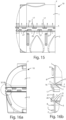
Figure 13 shows a side cutaway view of a third embodiment of the modular tank obtained through the assembly according to the invention; -
Figure 14a shows a cutaway and front sectional view of the modular tank ofFigure 13 along a plane passing through the y-axis; -
Figure 14b shows the detail XlVb ofFigure 14a ; -
Figure 15 shows a side cutaway and exploded view of the modular tank ofFigure 13 , before assembling the half-shells that compose it; -
Figure 16a shows a cutaway and exploded front sectional view of the modular tank ofFigure 15 along a plane passing through the y-axis; -
Figure 16b shows the detail XVIb ofFigure 16a ; -
Figure 17 shows a detailed perspective view of the modular tank ofFigure 13 , before assembling the half-shells that compose it; -
Figure 18 shows a detailed perspective view of the modular tank ofFigure 13 , after assembling the half-shells; -
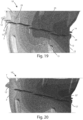
Figure 19 shows a detailed perspective and cutaway view of the modular tank ofFigure 1 , wherein the FEM analysis is depicted in grey scale; -
Figure 20 shows a detailed perspective and cutaway view of the modular tank ofFigure 19 , without the vertical panels, wherein the FEM analysis is depicted in grey scale; -
Figure 21a shows a cutaway and front sectional view of the modular tank ofFigure 1 along a plane passing through the y-axis, comprising internal tie rods; -
Figure 21b shows a cutaway and exploded front sectional view of the modular tank ofFigure 21a along a plane passing through the y-axis, before assembling the half-shells that compose it; -
Figure 22a shows the detail XXIIa ofFigure 21a ; -
Figure 22b shows the detail XXIIb ofFigure 21b ; -
Figure 23 shows a perspective cutaway view of the modular tank ofFigure 21a ; -
Figure 24 shows a perspective cutaway view of the modular tank ofFigure 21b ; -
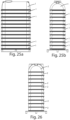
Figures 25a and 25b respectively show a side view and a front view of a plurality of first half-shells or upper half-shells of the modular tank ofFigure 1 stacked on one another for storage on a pallet; and -
Figure 26 shows a front view of a plurality of second half-shells or lower half-shells of the modular tank ofFigure 1 stacked on one another for storage on a pallet. - With reference to
Figures 1 - 6 , a first embodiment of the assembly for the formation of a modular tank according to the invention can be observed, indicated by thereference number 10. - In the following, reference will be made directly to the modular tank obtained by assembling different components of the assembly object of the invention.
- Said
modular tank 10 is preferably made of plastic material and consists of two half-shells - The
tank 10 could also be made of metallic material, even if more expensive. Preferably polymeric materials are used, such as polyethylene (PE), preferably thetank 10 is obtained using the rotational moulding technique. However, it can also be obtained by injection moulding, or blow moulding, or other methods. - The
tank 10 is preferably adapted to contain fluids, in particular liquids such as water, preferably water for domestic use. Thetank 10 consists of two portions, or half-shells, an upper half-shell 1 and a lower half-shell 2, designed to be stackable, which couple together on two specially made surfaces, between which agasket 4 is interposed, and which become integral with each other. This solution makes it possible to considerably reduce the cost for transporting the manufactured products thanks to the stackability of the half-shells, optimising the spaces intended for loads and reducing the environmental impact of this phase of the manufactured product's life cycle. - In particular, as can be seen in
Figures 25a, 25b and 26 , when they are transported or stored for transport, a plurality of first half-shells 1 stacked on one another and a plurality of second half-shells 2 stacked on one another are arranged. - In particular, each half-
shell shell - In some embodiments the two half-shells can be identical or distinct.
- In particular, said
tank 10 comprises a first half-shell or upper half-shell 1 and a second half-shell or lower half-shell 2. - Half-shells mean two portions of a shell, in this case a tank, which are adapted to protect the contents once they are coupled together. Such half-shells are provided with side walls and a connecting upper or lower wall. The upper half-shell is generally equipped with openings for accessing the contents, while the lower half-shell is generally equipped with a flat portion or legs for resting on the ground.
- In the present text, reference is made to outdoor tanks for the storage of liquids, in particular water for domestic use.
- Said
modular tank 10 according to the invention also provides coupling means for coupling said two half-shells - In particular, said two half-
shells coupling terminal edge lower edge 11 of the upper half-shell 1 and to theupper edge 21 of the lower half-shell 2. - Said half-
shells shells - The solution according to the invention provides a fastening system for constraining the two half-
shells gasket 4 to maintain a hydraulic sealing by its compression, and a constraint system along the X-plane which makes it possible to reduce the rotations caused by the hydrostatic thrust and the consequent separation of the half-shells which would cause thegasket 4 to lose compression and, consequently, cause the hydraulic sealing to fail. - A
gasket 4 is in fact interposed between the first half-shell 1 and the second lower half-shell 2 for the hydraulic sealing of themodular tank 1, once assembled and filled with the fluid to be stored. - The internal portions of said half-
shells coupling edges internal seat 3 for housing thegasket 4. - The geometry of the
gasket 4 is such as to make it possible to obtain the hydraulic sealing once the mechanical assembly process between the two half-shells shells coupling flanges gasket 4 and guarantee the sealing will be obtained. - With particular reference to
Figure 2b , it can be observed that in the specific embodiment, a first half-shell 1, in particular the upper half-shell 1, has an internalabutting flange 14 spaced from the respectiveterminal edge 11. In particular, said internal abuttingflange 14 is located in the internal part of the concavity of the half-shell 1. - The second half-
shell 2, on the other hand, has an "L"-shapedinternal flange 24 which departs from the respectiveterminal edge 21. When the two half-shells flange 14 of the first half-shell 1 and the "L"-shapedinternal flange 24 of the second half-shell 2 form saidhousing portion 3 for thegasket 4. - Furthermore, as can be always seen from
Figure 2b , thegasket 4 has a "U"-shaped cross section such as to fit onto said "L"-shapedinternal flange 24 of the second half-shell 2. As can be seen, such "U"-shapedgasket 4 therefore has twoside walls upper wall 43. - Again, a first
vertical wall 41 of thegasket 4 is provided with a plurality ofprotuberances 42 and is adapted to be fitted between said "L"-shapedinternal flange 24 of the second half-shell 2 and the internal wall of the first half-shell 1 when thetank 10 is in its assembled configuration. Finally, theupper wall 43 of thegasket 4 has an internalhollow portion 44 such that, when thetank 10 is in its assembled configuration, it is in abutment and compressed between the internal abuttingflange 14 of the first half-shell 1 and the upper portion of the "L"-shapedinternal flange 24 of the second half-shell 2. - In particular, such internal
hollow portion 44 will be compressed, guaranteeing the sealing thanks to the action of the internal abuttingflange 14 and to the opposition of the "L"-shapedinternal flange 24. - The study of the shapes of the
tank 10 is functional to guarantee a greater seal of thegasket 4 as the hydrostatic thrust acting on the walls of thetank 10 itself increases. - In particular, the
gasket 4 has a section functional for the purpose and made using the most common manufacturing processes such as moulding or extrusion processes. Alternatively, a closed-cell gasket having a regular section, for example a rectangular or circular one, can be used. In both cases, the higher the thrust on the tank walls, the more the gasket is compressed. In this way, the sealing is guaranteed in any operating condition. - An alternative is the use of a liquid gasket which, during the polymerisation phase, forms a closed-cell foam. In this case the geometry of the gasket will be dictated by the shape of the seat on which the gasket itself will be deposited.
- In particular, the liquid gasket may be of the FIPFG (formed in place foam gasket) type, due to its main characteristic of being in a very viscous liquid state, it tends to fill the shape that is available (seat) and, in contact with the air, begins to polymerise forming a closed-cell foam. In this way there is a good filling of the seat using a material which is able to fulfil the hydraulic sealing tasks in the best possible way.
- As an alternative, the liquid gasket may be of the FIPG (formed in place gasket) type, due to its main characteristic of being in a very viscous liquid state, it tends to fill the shape that is available (seat) and, in contact with the air, begins to polymerise forming a compact bead. In this way there is a good filling of the seat using a material which is able to fulfil the hydraulic sealing tasks in the best possible way.
- Each half-
shell terminal edge flanges toothed portions shells flange - In particular, said plurality of protruding
flanges terminal edge - Each protruding
flange shell shell flange shell - The
modular tank 10 therefore provides coupling means for coupling together the protrudingflanges shells - In the embodiment shown in the figures, with particular reference to
Figures 5 and 6 , it can be observed that at the side ends of eachflange respective holes 5 arranged in such a way as to allow the passage ofsuitable screws 6, eachscrew 6 being adapted to pass through theholes 5 obtained in the free ends of a pair offlanges flange 12 of the first half-shell 1 and aflange 22 of the second half-shell 2.Such screws 6 can be locked in place by means of bolted joints, in particular by means ofnuts 7 andwashers 8. - Such coupling means make it possible to create a simple and reliable mechanical block in the external part of the
tank 10, avoiding the separation of the two half-shells gasket 4 positioned in theinternal seat 3 by applying an initial compression. - Each
flange vertical extension external panel - The
external panels 13 of the first half-shell 1 are arranged on the face of therespective flange 12 facing the second half-shell 2, and theflat panels 23 of the second half-shell 2 are arranged on the face of therespective flange 22 facing the first half-shell 1, in such a way that when the half-shells external panels shell shell external panels gasket 4 positioned in theseat 3 with consequent leakage of the fluid contained inside thetank 10. - In the area of a
half shell external panels mutual half shell tank 10 is as if it were twice as thick as the wall thickness of each half-shell - In fact, when the
tank 10 is assembled, theexternal panels shell shell - This makes it possible to increase the resistance in the coupling area between the half-
shells - In this way, both half-
shells shell shell shell - In particular, such
external panels shell half shell - If the
tank 10 is made of polyethylene, since such material does not lend itself to flat shapes due to its poor mechanical properties, the extension of the linear portion is limited, otherwise high deformations would occur. - Preferably, the extension in height, intended as the extension along an axis parallel to the vertical y-axis of each
vertical extension shell - As regards the extension in width of each
vertical extension shell 1, intended as the extension parallel to theterminal edge vertical extension - Like the
flanges external panels shell - In particular, between two
flanges shell vertical extension shell modular tank 10 is therefore configured in such a way as to assume an assembled configuration by coupling together said half-shells vertical extensions shell vertical extensions shell shell vertical extension shell shell gasket 4 and securing together said one or more protrudingexternal flanges shells - The use of the
external panels shells tank 10. Another aspect which should not be underestimated is the effectiveness of the exchange of rheonomic constraints, given by theexternal panels shell shell - Furthermore, the centring and alignment of the half-
shells - The solution according to the invention makes it possible to obtain systems suitable for joining the parts in terms of quality and practicality thanks to the gasket for an optimal hydraulic sealing, and thanks to the mechanical fastening system.
- Generally speaking, the two half-
shells screws 6 arranged along the perimeter of thetank 10. Furthermore, the section of the area where the two half-shells gasket 4 is positioned, has been designed in such a way as to avoid the rotation caused by the hydrostatic thrust of theflanged part - For this purpose, there are
external abutment panels shells panels shell shell external panels tank 10. - The
external panels shells - Furthermore, since the
tank 10 is to be installed above ground, it has been developed in such a way that minimal fluid leakages do not occur in the area where the half-shells - Furthermore, as shown for the
modular tank 10 ofFigures 21a - 24 , to further reduce the deformations on the horizontal X-plane, it could be possible to usetie rods 9 placed in the internal part of themodular tank 10 when assembled.Suitable seats 5 can be made on theinternal flange 14, whose aim is to accommodate bolted joints, formed byscrews 6,nuts 7 andwashers 8, and to make thetie rod 9, preferably made of the same material as thetank 10, integral with theinternal flange 14 itself. - In this way, as already stated, the horizontal thrusts and therefore the deformations caused by the hydrostatic thrust of the fluid contained inside the
tank 10 itself are further and advantageously limited. This further solution for stiffening thetank 10 can be extended to all the embodiments described below. - Referring to
Figures 7 - 12 , a second embodiment of the modular tank according to the invention can be observed, always indicated by thereference number 10. - The
tank 10 of the second embodiment is similar to the one previously described and therefore the common elements are not described and have the same reference numbers. - The second embodiment of the
tank 10 according to the invention differs from the one previously described, in particular referring toFigure 1 , in that each half-shell flanges Such flanges - Consequently also the
vertical extensions external panels shell external panel terminal edge shell vertical extension - The smaller number of
flanges shells - Furthermore, as can be seen in particular from
Figures 8b and10b , at theterminal edge shell continuous seat 3, in particular having a semicircle section, for housing the gasket (not shown in the figure). - In particular, at each
terminal edge internal flange terminal edge - As hinted above, the
modular tank 10 according to the second embodiment is advantageously cheaper and requires a reduced installation time, given the smaller number of screws. However, the resistance at the flanged part is lower and the deformations are higher. -
Figures 13 - 18 show a third embodiment of themodular tank 10 according to the invention. - The
tank 10 of the third embodiment is similar to those previously described and therefore the common elements will not be described and have the same reference numbers. - The third embodiment of the
tank 10 according to the invention differs from the second embodiment in that each half-shell external flange terminal edge shell external flange external flange holes 5, arranged so as to allow the passage ofrespective screws 6 for coupling together the two half-shells - At each
external flange vertical extensions external panels panels shell external flange panels shell - Furthermore, each shaped
panel 17 of the first half-shell 1 is arranged on the face of theexternal flange 16 facing the second half-shell 2, and each shapedpanel 27 of the second half-shell 2 is arranged on the face of the respectiveexternal flange 26 facing the first half-shell 1, in such a way that when the half-shells panels shell shell shell panels shell - In particular, as can be seen in
Figure 14b , said shapedpanels modular tank 10 is in its assembled configuration, the shapedpanels shell 1; 2 are interlocked on the protrudingexternal flange 26; 16 of the mutual half-shell 2; 1. More specifically, a first portion or first curve of the "S"-shaped section of the shapedpanel shell shell panel shell external flange 26; 16 of the mutual half-shell panel - Such shaped
panels terminal edge seat 3 with consequent leakage of the fluid contained inside thetank 10. - The particular geometry of the shaped
panels external flange shell panel shell - In this way, both half-
shells shell shell shell - The particular geometry of the shaped
panels shell 1 and the lower half-shell 2 by exploiting the elastic component of the material constituting the two parts of thetank 10 in order to pass theexternal flanges shells external flanges shells shells - Advantageously, the solution according to the present invention allows the two half-
shells - Furthermore, the solutions described according to the present invention make it possible to make the coupling of the half-
shells - Advantageously, the fastening means between the half-shells of the tank do not have added pins or mechanical inserts, using conventional fastening means such as screws and bolts. This makes it possible to reduce the assembly time of the half-shells, which can also be performed by non-professional personnel.
- Due to the poor mechanical properties of the polymers used, to increase the resistance of the manufactured products it was decided to work on the geometry of the manufactured product so as to exploit certain shapes for increasing the resistance in the areas subjected to the greatest stresses.
- The tanks according to one of the described embodiments are suitable for being manufactured using the rotational moulding technique, or even using the injection or blow moulding techniques; thanks to the simplicity of the shapes, the material is able to flow freely inside the mould, replicating its shape in the best possible way. The total absence of undercuts will also allow an extremely simple extraction of the piece from the mould.
- Furthermore, another advantage of the tank according to the invention is the intrinsic stiffness which makes it possible to have a high localised stiffness, limiting as much as possible the deformations of the coupling area. Should the hydrostatic thrust induce bending moments on the walls of the tank, the presence of external or internal extensions makes it possible to hinder the induced rotations given that the wall of a half-shell rests on the opposite half-shell offering resistance to deformations through the exchange of mutual interactions. Thanks to the geometry of the manufactured product, this phenomenon is present along the entire perimeter of the coupling area and the resistance can be considered uniform. Studies carried out using a finite element analysis (FEM) confirmed the described behavior: the same manufactured product with (
Figure 19 ) and without (Figure 20 ) the internal or external extensions presents a deformation induced by the bending moment which is generated because of the totally different hydrostatic thrust: present in the manufactured product without the aforementioned extensions and absent in the manufactured product where the extensions are present. - As can be seen from
Figures 19 and 20 , the area where there is a darker shade of grey corresponds to the regions where the deformation is greater, compared to the areas with a lighter shade of gray. As can be seen, the darkest area is wider in the version without the vertical walls ofFigure 20 . - In the foregoing the preferred embodiments have been described and variants of the present invention have been suggested, but it should be understood that those skilled in the art will be able to make modifications and changes without thereby departing from the corresponding scope of protection, as defined by the attached claims.
Claims (21)
- An assembly (10) for the formation of a modular tank (10) for containing a fluid, said assembly (10) comprising a first half-shell (1), and a second half-shell (2), each half-shell (1; 2) providing a body having a bottom wall and side walls ending in a terminal edge (11; 21) for coupling at a horizontal coupling plane (X) with the terminal edge (21; 11) of the other half-shell (2; 1), said assembly (10) further comprising a gasket (4) that can be interposed between said two half-shells (1, 2) at the terminal edges (11, 21), and fastening means (6, 7, 8) for securing together said half-shells (1, 2) and preventing their movement along a vertical axis (y) perpendicular to the horizontal plane (X), each half-shell (1; 2) at the respective terminal edge (11, 21) providing one or more protruding external flanges (12; 16; 22; 26), each half-shell (1; 2) further providing a plurality of vertical extensions (13; 17; 23; 27) arranged externally on the respective terminal edge (11; 21) projecting along said vertical axis (y) in an opposite direction to the body of the respective half-shell (1; 2), said assembly (10) being characterised in that each vertical extension (13; 17; 23; 27) of each half-shell (1; 2) has at least one portion parallel to said vertical axis (y), in that each half-shell (1; 2) provides a plurality of housing seats, each housing seat being arranged externally on the respective terminal edge (11; 21) and corresponding to the interspace between two vertical extensions (13; 17; 23; 27) of the same half-shell (1; 2), said interspace having no vertical extensions, and in that said assembly (10) is configured in such a way as to assume an assembled tank configuration by coupling together said two half-shells (1, 2) with their respective terminal edges (11, 21) in correspondence with said horizontal plane (X), arranging the vertical extensions (13; 17; 23; 27) of a first half-shell (1; 2) alternately to the vertical extensions (23; 27; 13; 17) of the second half-shell (2; 1) and so as to be projecting towards the mutual half-shell (2; 1) in such a way that each vertical extension (23; 27; 13; 17) of a half-shell (1; 2) fits into the respective interspace between two vertical extensions (23; 27; 13; 17) of the mutual half-shell (2; 1) so as to be adjacent to the side wall of the body of the mutual half-shell (2; 1), interposing said gasket (4) and securing together said one or more protruding external flanges (12; 16; 22; 26) of the two half-shells (1, 2) through said fastening means (6, 7, 8).
- The assembly (10) according to the preceding claim, wherein one or more holes (5) are obtained on said one or more protruding external flanges (12; 16; 22; 26) for the passage of said fastening means (6, 7, 8) for securing together said half-shells (1, 2).
- The assembly (10) according to claim 1 or 2, wherein each half-shell (1; 2) comprises a plurality of protruding external flanges (12; 22), each protruding external flange (12; 22) having a flat surface substantially parallel to the horizontal plane (X).
- The assembly (10) according to the preceding claim, wherein in each half-shell (1; 2) said plurality of protruding external flanges (12, 22) is arranged radially to a plane parallel to said horizontal plane (X) on the respective terminal edge (11, 21), more particularly equidistantly on the perimeter of the respective terminal edge (11, 21).
- The assembly (10) according to claim 3 or 4, wherein each protruding external flange (12; 22) of a half-shell (1; 2) is spaced from the adjacent protruding external flange (12; 22) by a distance such that when the assembly (10) is in its assembled tank configuration, each of the two side ends of each protruding external flange (12; 22) of each half-shell (1; 2) overlaps a respective side end of a protruding external flange (22; 12) of the mutual half-shell (2, 1).
- The assembly (10) according to any one of the preceding claims, wherein each vertical extension (13; 23) of each half-shell (1; 2) is arranged on a respective protruding external flange (12; 22) of said plurality of protruding external flanges (12; 22) and wherein each housing seat of the corresponding half-shell (1; 2) further corresponds to the interspace between two protruding external flanges (12; 22) of the same half-shell (1; 2).
- The assembly (10) according to any one of the preceding claims, wherein each vertical extension (13; 23) of each half-shell (1, 2) has the entire flat surface with vertical development, parallel to the vertical axis (y).
- The assembly (10) according to any one of claims 1 or 2, wherein each half-shell (1; 2) comprises a single protruding external flange (16; 26), wherein each vertical extension (17; 27) of each half-shell (1; 2) is arranged on the respective protruding external flange (16; 26) and is a shaped panel (17; 27) having a hooking portion, said assembly (10) being configured in such a way that when said half-shells (1; 2) are coupled together at the terminal edges (11; 21) the respective shaped panels (17; 27) of a half-shell (1; 2) are interlocked on the protruding external flange (26; 16) of the mutual half-shell (2; 1) at the respective interspace between two vertical extensions (27; 17) of the mutual half-shell (2; 1).
- The assembly (10) according to the preceding claim, wherein each shaped panel (17; 27) of each half-shell (1; 2) has an "S"-shaped cross-section and is configured in such a way that when the assembly (10) is in its assembled tank configuration, the portion parallel to said vertical axis (y) of said "S"-shaped section of the shaped panel (17; 27) of each half-shell (1; 2) is arranged externally tangent to the side wall of the body of the mutual half-shell (2; 1).
- The assembly (10) according to any one of the preceding claims, wherein a housing portion (3) is obtained at said terminal edge (11; 21) of at least one half-shell (1; 2) for housing said gasket (4) when said assembly (10) is in its assembled tank configuration.
- The assembly (10) according to claim 10, wherein a first half-shell (1) has an internal abutting flange (14) spaced from said terminal edge (11), wherein the second half-shell (2) has an "L"-shaped internal flange (24), wherein when said two half-shells (1, 2) are coupled together said internal abutting flange (14) of the first half-shell (1) and said "L"-shaped internal flange (24) of the second half-shell (2) form said housing portion (3) for said gasket (4).
- The assembly (10) according to the preceding claim, wherein said gasket (4) has a "U"-shaped cross section such as to be fitted onto said "L"-shaped internal flange (24) of the second half-shell (2) when the assembly (10) is assembled, wherein a first vertical wall (41) of said gasket (4) is provided with a plurality of protuberances (42) and is adapted to be fitted between said "L"-shaped internal flange (24) of the second half-shell (2) and the internal wall of said first half-shell (1) when the assembly (10) is in its assembled tank configuration, and wherein the upper wall (43) of said gasket (4) has an internal hollow portion (44) such that, when the assembly (10) is in its assembled tank configuration, it is in abutment and compressed between the internal abutting flange (14) of the first half-shell (1) and the upper portion of the "L"-shaped internal flange (24) of the second half-shell (2).
- The assembly (10) according to claim 10, wherein said gasket is a gasket of the FIPFG or FIPG type, introduced in liquid phase into said housing portion (3) obtained in one of said two half-shells (1; 2).
- The assembly (10) according to any one of the preceding claims, wherein said assembly (10) further comprises one or more tie rods (9), wherein at least one first half-shell (1) has a protruding internal flange (14) provided with a plurality of holes (5), wherein when said assembly (10) is assembled each tie rod (9) is coupled to two opposite sides of said protruding internal flange (14) by means of fastening means (6, 7, 8) at respective holes (5).
- The assembly (10) according to any one of the preceding claims, when depending on claim 2 or 14, wherein said fastening means provide a plurality of screws (6), each screw (6) being adapted to pass through the respective hole (5), and wherein said fastening means further provide a plurality of nuts (7) and washers (8) for locking said screws (6) in place.
- The assembly (10) according to any one of the preceding claims, wherein the body of each of said half-shells (1, 2) has a flared internal shape such as to allow half-shells (1; 2) of the same or different type to be stacked one inside the other.
- The assembly (10) according to any one of the preceding claims, wherein said assembly (10) is made of polymeric material, preferably polyethylene.
- The assembly (10) according to any one of the preceding claims, wherein the extension along an axis parallel to the vertical axis (y) of each vertical extension (13; 17; 23; 27) of a half-shell (1; 2) is between five and six times the thickness of the wall of such half-shell (1; 2).
- The assembly (10) according to any one of the preceding claims, wherein said one or more protruding flanges (12; 16; 22; 26) of each half-shell (1; 2) are integral with the wall of the respective half-shell (1; 2), wherein the vertical extensions (13; 17; 23; 27) of each half-shell (1; 2) are integral with the respective one or more protruding external flanges (12; 16; 22; 26) of the same half-shell (1; 2).
- The assembly (10) according to any one of the preceding claims, wherein the extension parallel to the terminal edge (11; 21) of each vertical extension (13; 17; 23; 27) of a half-shell (1; 2) is between two and ten times its height along an axis parallel to the vertical axis (y).
- A modular tank (10) obtained from the assembly according to any one of the preceding claims in its assembled tank configuration.
Applications Claiming Priority (1)
| Application Number | Priority Date | Filing Date | Title |
|---|---|---|---|
| IT102021000032441A IT202100032441A1 (en) | 2021-12-23 | 2021-12-23 | Modular tank |
Publications (3)
| Publication Number | Publication Date |
|---|---|
| EP4201841A2 true EP4201841A2 (en) | 2023-06-28 |
| EP4201841A3 EP4201841A3 (en) | 2023-10-11 |
| EP4201841B1 EP4201841B1 (en) | 2025-07-16 |
Family
ID=80624979
Family Applications (1)
| Application Number | Title | Priority Date | Filing Date |
|---|---|---|---|
| EP22216002.0A Active EP4201841B1 (en) | 2021-12-23 | 2022-12-22 | Assembly for the formation of a modular tank and modular tank |
Country Status (2)
| Country | Link |
|---|---|
| EP (1) | EP4201841B1 (en) |
| IT (1) | IT202100032441A1 (en) |
Citations (7)
| Publication number | Priority date | Publication date | Assignee | Title |
|---|---|---|---|---|
| US4333580A (en) | 1980-09-29 | 1982-06-08 | Associated Plastics, Inc. | Mechanism for locking two halves of an underground vault |
| DE9416968U1 (en) | 1994-10-24 | 1994-12-15 | Durotherm Kunststoffverarbeitung Gmbh, 72221 Haiterbach | Thermoformed plastic tank |
| US7854338B2 (en) | 2006-09-04 | 2010-12-21 | Graf Plastics Gmbh | Water tank and method for manufacturing a water tank |
| US8740005B1 (en) | 2011-03-04 | 2014-06-03 | Infiltrator Systems, Inc. | Plastic tank having a clamped joint |
| US10427356B1 (en) | 2016-01-22 | 2019-10-01 | Infiltrator Water Technologies Llc | Plastic tank having a welded frusto-conical flange joint |
| US10696448B1 (en) | 2016-01-22 | 2020-06-30 | Infiltrator Water Technologies Llc | Making a plastic tank with an integrity-verifiable weld joint |
| US10723080B1 (en) | 2016-01-22 | 2020-07-28 | Infiltrator Water Technologies, Llc | Making a plastic tank having a weld joint by using a resilient clamp |
Family Cites Families (6)
| Publication number | Priority date | Publication date | Assignee | Title |
|---|---|---|---|---|
| JPS5099508U (en) * | 1974-01-14 | 1975-08-18 | ||
| JPS5313054Y2 (en) * | 1974-01-30 | 1978-04-08 | ||
| EP0064310A3 (en) * | 1981-05-05 | 1983-01-26 | A.G. INTERNATIONAL S.p.A. | Plastics tank |
| JPS5830971A (en) * | 1981-08-11 | 1983-02-23 | 昭和ゴム株式会社 | Shroud structure |
| JP2008144911A (en) * | 2006-12-12 | 2008-06-26 | Three Bond Co Ltd | Sealing structure |
| DE102010000088B4 (en) * | 2010-01-15 | 2011-09-22 | Sonderhoff Chemicals Gmbh | Method and device for producing polymer laminations or strand-like applications on a substrate |
-
2021
- 2021-12-23 IT IT102021000032441A patent/IT202100032441A1/en unknown
-
2022
- 2022-12-22 EP EP22216002.0A patent/EP4201841B1/en active Active
Patent Citations (7)
| Publication number | Priority date | Publication date | Assignee | Title |
|---|---|---|---|---|
| US4333580A (en) | 1980-09-29 | 1982-06-08 | Associated Plastics, Inc. | Mechanism for locking two halves of an underground vault |
| DE9416968U1 (en) | 1994-10-24 | 1994-12-15 | Durotherm Kunststoffverarbeitung Gmbh, 72221 Haiterbach | Thermoformed plastic tank |
| US7854338B2 (en) | 2006-09-04 | 2010-12-21 | Graf Plastics Gmbh | Water tank and method for manufacturing a water tank |
| US8740005B1 (en) | 2011-03-04 | 2014-06-03 | Infiltrator Systems, Inc. | Plastic tank having a clamped joint |
| US10427356B1 (en) | 2016-01-22 | 2019-10-01 | Infiltrator Water Technologies Llc | Plastic tank having a welded frusto-conical flange joint |
| US10696448B1 (en) | 2016-01-22 | 2020-06-30 | Infiltrator Water Technologies Llc | Making a plastic tank with an integrity-verifiable weld joint |
| US10723080B1 (en) | 2016-01-22 | 2020-07-28 | Infiltrator Water Technologies, Llc | Making a plastic tank having a weld joint by using a resilient clamp |
Also Published As
| Publication number | Publication date |
|---|---|
| EP4201841A3 (en) | 2023-10-11 |
| EP4201841B1 (en) | 2025-07-16 |
| IT202100032441A1 (en) | 2023-06-23 |
Similar Documents
| Publication | Publication Date | Title |
|---|---|---|
| CA1201392A (en) | Freight container | |
| US5513474A (en) | Double-walled formwork element and process for manufacturing it | |
| US4751945A (en) | Dual containment channel for fluids | |
| CA2314819C (en) | Septic waste treatment system | |
| AU715342B2 (en) | Container for bulk materials | |
| US3799383A (en) | Transcontainer for flowable material | |
| EP1616803A1 (en) | Collapsible bulk container | |
| EP2931631B1 (en) | Modular tanks, method for constructing a modular tank and kit for constructing a modular tank | |
| EP4201841B1 (en) | Assembly for the formation of a modular tank and modular tank | |
| WO1994016974A1 (en) | Modular containment system for hazardous materials | |
| CN211845325U (en) | An assembled panel storage box and a prefabricated unit panel for manufacturing the assembled panel storage box | |
| US11098850B2 (en) | Storage tank containment system | |
| US20220056723A1 (en) | Parts assembly, panel, and tank | |
| NO20220270A1 (en) | Membrane tank feasible for cryogenic service | |
| US5497895A (en) | Transport container | |
| US20160319990A1 (en) | Storage Tank Containment System | |
| EP4442607A1 (en) | Modular tank | |
| FR3125871A3 (en) | Thermal accumulator | |
| US6874651B2 (en) | Sealed and resistant tank | |
| WO2017074538A1 (en) | Storage tank containment system | |
| AU2009200435A1 (en) | Pressure Cylinder | |
| IT202100032456A1 (en) | Modular tank | |
| WO2017200503A2 (en) | Prefabricated and modular storage tanks for storing water or other liquids | |
| KR100783798B1 (en) | Storage tank | |
| CN1382093A (en) | Delivery device for liquids |
Legal Events
| Date | Code | Title | Description |
|---|---|---|---|
| PUAI | Public reference made under article 153(3) epc to a published international application that has entered the european phase |
Free format text: ORIGINAL CODE: 0009012 |
|
| STAA | Information on the status of an ep patent application or granted ep patent |
Free format text: STATUS: THE APPLICATION HAS BEEN PUBLISHED |
|
| AK | Designated contracting states |
Kind code of ref document: A2 Designated state(s): AL AT BE BG CH CY CZ DE DK EE ES FI FR GB GR HR HU IE IS IT LI LT LU LV MC ME MK MT NL NO PL PT RO RS SE SI SK SM TR |
|
| PUAL | Search report despatched |
Free format text: ORIGINAL CODE: 0009013 |
|
| AK | Designated contracting states |
Kind code of ref document: A3 Designated state(s): AL AT BE BG CH CY CZ DE DK EE ES FI FR GB GR HR HU IE IS IT LI LT LU LV MC ME MK MT NL NO PL PT RO RS SE SI SK SM TR |
|
| RIC1 | Information provided on ipc code assigned before grant |
Ipc: B65D 90/08 20060101ALI20230906BHEP Ipc: B65D 88/06 20060101AFI20230906BHEP |
|
| P01 | Opt-out of the competence of the unified patent court (upc) registered |
Effective date: 20230911 |
|
| STAA | Information on the status of an ep patent application or granted ep patent |
Free format text: STATUS: REQUEST FOR EXAMINATION WAS MADE |
|
| 17P | Request for examination filed |
Effective date: 20240411 |
|
| RBV | Designated contracting states (corrected) |
Designated state(s): AL AT BE BG CH CY CZ DE DK EE ES FI FR GB GR HR HU IE IS IT LI LT LU LV MC ME MK MT NL NO PL PT RO RS SE SI SK SM TR |
|
| GRAP | Despatch of communication of intention to grant a patent |
Free format text: ORIGINAL CODE: EPIDOSNIGR1 |
|
| STAA | Information on the status of an ep patent application or granted ep patent |
Free format text: STATUS: GRANT OF PATENT IS INTENDED |
|
| INTG | Intention to grant announced |
Effective date: 20250310 |
|
| GRAS | Grant fee paid |
Free format text: ORIGINAL CODE: EPIDOSNIGR3 |
|
| GRAA | (expected) grant |
Free format text: ORIGINAL CODE: 0009210 |
|
| STAA | Information on the status of an ep patent application or granted ep patent |
Free format text: STATUS: THE PATENT HAS BEEN GRANTED |
|
| AK | Designated contracting states |
Kind code of ref document: B1 Designated state(s): AL AT BE BG CH CY CZ DE DK EE ES FI FR GB GR HR HU IE IS IT LI LT LU LV MC ME MK MT NL NO PL PT RO RS SE SI SK SM TR |
|
| REG | Reference to a national code |
Ref country code: GB Ref legal event code: FG4D |
|
| REG | Reference to a national code |
Ref country code: CH Ref legal event code: EP |
|
| REG | Reference to a national code |
Ref country code: DE Ref legal event code: R096 Ref document number: 602022017626 Country of ref document: DE |
|
| REG | Reference to a national code |
Ref country code: IE Ref legal event code: FG4D |
|
| REG | Reference to a national code |
Ref country code: NL Ref legal event code: MP Effective date: 20250716 |
|
| PG25 | Lapsed in a contracting state [announced via postgrant information from national office to epo] |
Ref country code: PT Free format text: LAPSE BECAUSE OF FAILURE TO SUBMIT A TRANSLATION OF THE DESCRIPTION OR TO PAY THE FEE WITHIN THE PRESCRIBED TIME-LIMIT Effective date: 20251117 |
|
| PG25 | Lapsed in a contracting state [announced via postgrant information from national office to epo] |
Ref country code: NL Free format text: LAPSE BECAUSE OF FAILURE TO SUBMIT A TRANSLATION OF THE DESCRIPTION OR TO PAY THE FEE WITHIN THE PRESCRIBED TIME-LIMIT Effective date: 20250716 |
|
| REG | Reference to a national code |
Ref country code: AT Ref legal event code: MK05 Ref document number: 1813884 Country of ref document: AT Kind code of ref document: T Effective date: 20250716 |
|
| PG25 | Lapsed in a contracting state [announced via postgrant information from national office to epo] |
Ref country code: IS Free format text: LAPSE BECAUSE OF FAILURE TO SUBMIT A TRANSLATION OF THE DESCRIPTION OR TO PAY THE FEE WITHIN THE PRESCRIBED TIME-LIMIT Effective date: 20251116 |
|
| PGFP | Annual fee paid to national office [announced via postgrant information from national office to epo] |
Ref country code: DE Payment date: 20250930 Year of fee payment: 4 |
|
| PG25 | Lapsed in a contracting state [announced via postgrant information from national office to epo] |
Ref country code: NO Free format text: LAPSE BECAUSE OF FAILURE TO SUBMIT A TRANSLATION OF THE DESCRIPTION OR TO PAY THE FEE WITHIN THE PRESCRIBED TIME-LIMIT Effective date: 20251016 |
|
| REG | Reference to a national code |
Ref country code: LT Ref legal event code: MG9D |
|
| PG25 | Lapsed in a contracting state [announced via postgrant information from national office to epo] |
Ref country code: AT Free format text: LAPSE BECAUSE OF FAILURE TO SUBMIT A TRANSLATION OF THE DESCRIPTION OR TO PAY THE FEE WITHIN THE PRESCRIBED TIME-LIMIT Effective date: 20250716 |
|
| PG25 | Lapsed in a contracting state [announced via postgrant information from national office to epo] |
Ref country code: FI Free format text: LAPSE BECAUSE OF FAILURE TO SUBMIT A TRANSLATION OF THE DESCRIPTION OR TO PAY THE FEE WITHIN THE PRESCRIBED TIME-LIMIT Effective date: 20250716 |
|
| PG25 | Lapsed in a contracting state [announced via postgrant information from national office to epo] |
Ref country code: HR Free format text: LAPSE BECAUSE OF FAILURE TO SUBMIT A TRANSLATION OF THE DESCRIPTION OR TO PAY THE FEE WITHIN THE PRESCRIBED TIME-LIMIT Effective date: 20250716 |
|
| PGFP | Annual fee paid to national office [announced via postgrant information from national office to epo] |
Ref country code: FR Payment date: 20251110 Year of fee payment: 4 |
|
| PG25 | Lapsed in a contracting state [announced via postgrant information from national office to epo] |
Ref country code: GR Free format text: LAPSE BECAUSE OF FAILURE TO SUBMIT A TRANSLATION OF THE DESCRIPTION OR TO PAY THE FEE WITHIN THE PRESCRIBED TIME-LIMIT Effective date: 20251017 |
|
| PG25 | Lapsed in a contracting state [announced via postgrant information from national office to epo] |
Ref country code: SE Free format text: LAPSE BECAUSE OF FAILURE TO SUBMIT A TRANSLATION OF THE DESCRIPTION OR TO PAY THE FEE WITHIN THE PRESCRIBED TIME-LIMIT Effective date: 20250716 |
|
| PG25 | Lapsed in a contracting state [announced via postgrant information from national office to epo] |
Ref country code: LV Free format text: LAPSE BECAUSE OF FAILURE TO SUBMIT A TRANSLATION OF THE DESCRIPTION OR TO PAY THE FEE WITHIN THE PRESCRIBED TIME-LIMIT Effective date: 20250716 |
|
| PG25 | Lapsed in a contracting state [announced via postgrant information from national office to epo] |
Ref country code: BG Free format text: LAPSE BECAUSE OF FAILURE TO SUBMIT A TRANSLATION OF THE DESCRIPTION OR TO PAY THE FEE WITHIN THE PRESCRIBED TIME-LIMIT Effective date: 20250716 Ref country code: PL Free format text: LAPSE BECAUSE OF FAILURE TO SUBMIT A TRANSLATION OF THE DESCRIPTION OR TO PAY THE FEE WITHIN THE PRESCRIBED TIME-LIMIT Effective date: 20250716 |
|
| PG25 | Lapsed in a contracting state [announced via postgrant information from national office to epo] |
Ref country code: RS Free format text: LAPSE BECAUSE OF FAILURE TO SUBMIT A TRANSLATION OF THE DESCRIPTION OR TO PAY THE FEE WITHIN THE PRESCRIBED TIME-LIMIT Effective date: 20251016 |
|
| PG25 | Lapsed in a contracting state [announced via postgrant information from national office to epo] |
Ref country code: ES Free format text: LAPSE BECAUSE OF FAILURE TO SUBMIT A TRANSLATION OF THE DESCRIPTION OR TO PAY THE FEE WITHIN THE PRESCRIBED TIME-LIMIT Effective date: 20250716 |
|
| PG25 | Lapsed in a contracting state [announced via postgrant information from national office to epo] |
Ref country code: RO Free format text: LAPSE BECAUSE OF FAILURE TO SUBMIT A TRANSLATION OF THE DESCRIPTION OR TO PAY THE FEE WITHIN THE PRESCRIBED TIME-LIMIT Effective date: 20250716 |
|
| PG25 | Lapsed in a contracting state [announced via postgrant information from national office to epo] |
Ref country code: SM Free format text: LAPSE BECAUSE OF FAILURE TO SUBMIT A TRANSLATION OF THE DESCRIPTION OR TO PAY THE FEE WITHIN THE PRESCRIBED TIME-LIMIT Effective date: 20250716 |
|
| PG25 | Lapsed in a contracting state [announced via postgrant information from national office to epo] |
Ref country code: DK Free format text: LAPSE BECAUSE OF FAILURE TO SUBMIT A TRANSLATION OF THE DESCRIPTION OR TO PAY THE FEE WITHIN THE PRESCRIBED TIME-LIMIT Effective date: 20250716 |
|
| PGFP | Annual fee paid to national office [announced via postgrant information from national office to epo] |
Ref country code: IT Payment date: 20251231 Year of fee payment: 4 |
|
| REG | Reference to a national code |
Ref country code: DE Ref legal event code: R097 Ref document number: 602022017626 Country of ref document: DE |
|
| PG25 | Lapsed in a contracting state [announced via postgrant information from national office to epo] |
Ref country code: CZ Free format text: LAPSE BECAUSE OF FAILURE TO SUBMIT A TRANSLATION OF THE DESCRIPTION OR TO PAY THE FEE WITHIN THE PRESCRIBED TIME-LIMIT Effective date: 20250716 |
|
| PG25 | Lapsed in a contracting state [announced via postgrant information from national office to epo] |
Ref country code: EE Free format text: LAPSE BECAUSE OF FAILURE TO SUBMIT A TRANSLATION OF THE DESCRIPTION OR TO PAY THE FEE WITHIN THE PRESCRIBED TIME-LIMIT Effective date: 20250716 Ref country code: SK Free format text: LAPSE BECAUSE OF FAILURE TO SUBMIT A TRANSLATION OF THE DESCRIPTION OR TO PAY THE FEE WITHIN THE PRESCRIBED TIME-LIMIT Effective date: 20250716 |
|
| PLBE | No opposition filed within time limit |
Free format text: ORIGINAL CODE: 0009261 |
|
| STAA | Information on the status of an ep patent application or granted ep patent |
Free format text: STATUS: NO OPPOSITION FILED WITHIN TIME LIMIT |
|
| REG | Reference to a national code |
Ref country code: CH Ref legal event code: L10 Free format text: ST27 STATUS EVENT CODE: U-0-0-L10-L00 (AS PROVIDED BY THE NATIONAL OFFICE) Effective date: 20260528 |
|
| 26N | No opposition filed |
Effective date: 20260417 |
|
| PG25 | Lapsed in a contracting state [announced via postgrant information from national office to epo] |
Ref country code: LT Free format text: LAPSE BECAUSE OF FAILURE TO SUBMIT A TRANSLATION OF THE DESCRIPTION OR TO PAY THE FEE WITHIN THE PRESCRIBED TIME-LIMIT Effective date: 20250716 |
|
| PG25 | Lapsed in a contracting state [announced via postgrant information from national office to epo] |
Ref country code: MC Free format text: LAPSE BECAUSE OF FAILURE TO SUBMIT A TRANSLATION OF THE DESCRIPTION OR TO PAY THE FEE WITHIN THE PRESCRIBED TIME-LIMIT Effective date: 20250716 |
|
| REG | Reference to a national code |
Ref country code: CH Ref legal event code: H13 Free format text: ST27 STATUS EVENT CODE: U-0-0-H10-H13 (AS PROVIDED BY THE NATIONAL OFFICE) Effective date: 20260723 |