EP4201774A1 - Industrial vehicle and method for controlling industrial vehicle - Google Patents
Industrial vehicle and method for controlling industrial vehicle Download PDFInfo
- Publication number
- EP4201774A1 EP4201774A1 EP22213778.8A EP22213778A EP4201774A1 EP 4201774 A1 EP4201774 A1 EP 4201774A1 EP 22213778 A EP22213778 A EP 22213778A EP 4201774 A1 EP4201774 A1 EP 4201774A1
- Authority
- EP
- European Patent Office
- Prior art keywords
- driver
- state
- mode
- unseated
- controller
- Prior art date
- Legal status (The legal status is an assumption and is not a legal conclusion. Google has not performed a legal analysis and makes no representation as to the accuracy of the status listed.)
- Granted
Links
Images


Classifications
-
- B—PERFORMING OPERATIONS; TRANSPORTING
- B60—VEHICLES IN GENERAL
- B60W—CONJOINT CONTROL OF VEHICLE SUB-UNITS OF DIFFERENT TYPE OR DIFFERENT FUNCTION; CONTROL SYSTEMS SPECIALLY ADAPTED FOR HYBRID VEHICLES; ROAD VEHICLE DRIVE CONTROL SYSTEMS FOR PURPOSES NOT RELATED TO THE CONTROL OF A PARTICULAR SUB-UNIT
- B60W30/00—Purposes of road vehicle drive control systems not related to the control of a particular sub-unit, e.g. of systems using conjoint control of vehicle sub-units
- B60W30/18—Propelling the vehicle
- B60W30/182—Selecting between different operative modes, e.g. comfort and performance modes
-
- B—PERFORMING OPERATIONS; TRANSPORTING
- B60—VEHICLES IN GENERAL
- B60K—ARRANGEMENT OR MOUNTING OF PROPULSION UNITS OR OF TRANSMISSIONS IN VEHICLES; ARRANGEMENT OR MOUNTING OF PLURAL DIVERSE PRIME-MOVERS IN VEHICLES; AUXILIARY DRIVES FOR VEHICLES; INSTRUMENTATION OR DASHBOARDS FOR VEHICLES; ARRANGEMENTS IN CONNECTION WITH COOLING, AIR INTAKE, GAS EXHAUST OR FUEL SUPPLY OF PROPULSION UNITS IN VEHICLES
- B60K28/00—Safety devices for propulsion-unit control, specially adapted for, or arranged in, vehicles, e.g. preventing fuel supply or ignition in the event of potentially dangerous conditions
- B60K28/02—Safety devices for propulsion-unit control, specially adapted for, or arranged in, vehicles, e.g. preventing fuel supply or ignition in the event of potentially dangerous conditions responsive to conditions relating to the driver
- B60K28/04—Safety devices for propulsion-unit control, specially adapted for, or arranged in, vehicles, e.g. preventing fuel supply or ignition in the event of potentially dangerous conditions responsive to conditions relating to the driver responsive to presence or absence of the driver, e.g. to weight or lack thereof
-
- B—PERFORMING OPERATIONS; TRANSPORTING
- B60—VEHICLES IN GENERAL
- B60W—CONJOINT CONTROL OF VEHICLE SUB-UNITS OF DIFFERENT TYPE OR DIFFERENT FUNCTION; CONTROL SYSTEMS SPECIALLY ADAPTED FOR HYBRID VEHICLES; ROAD VEHICLE DRIVE CONTROL SYSTEMS FOR PURPOSES NOT RELATED TO THE CONTROL OF A PARTICULAR SUB-UNIT
- B60W30/00—Purposes of road vehicle drive control systems not related to the control of a particular sub-unit, e.g. of systems using conjoint control of vehicle sub-units
- B60W30/18—Propelling the vehicle
- B60W30/18009—Propelling the vehicle related to particular drive situations
-
- B—PERFORMING OPERATIONS; TRANSPORTING
- B60—VEHICLES IN GENERAL
- B60W—CONJOINT CONTROL OF VEHICLE SUB-UNITS OF DIFFERENT TYPE OR DIFFERENT FUNCTION; CONTROL SYSTEMS SPECIALLY ADAPTED FOR HYBRID VEHICLES; ROAD VEHICLE DRIVE CONTROL SYSTEMS FOR PURPOSES NOT RELATED TO THE CONTROL OF A PARTICULAR SUB-UNIT
- B60W50/00—Details of control systems for road vehicle drive control not related to the control of a particular sub-unit, e.g. process diagnostic or vehicle driver interfaces
- B60W50/0098—Details of control systems ensuring comfort, safety or stability not otherwise provided for
-
- B—PERFORMING OPERATIONS; TRANSPORTING
- B60—VEHICLES IN GENERAL
- B60W—CONJOINT CONTROL OF VEHICLE SUB-UNITS OF DIFFERENT TYPE OR DIFFERENT FUNCTION; CONTROL SYSTEMS SPECIALLY ADAPTED FOR HYBRID VEHICLES; ROAD VEHICLE DRIVE CONTROL SYSTEMS FOR PURPOSES NOT RELATED TO THE CONTROL OF A PARTICULAR SUB-UNIT
- B60W50/00—Details of control systems for road vehicle drive control not related to the control of a particular sub-unit, e.g. process diagnostic or vehicle driver interfaces
- B60W50/08—Interaction between the driver and the control system
- B60W50/082—Selecting or switching between different modes of propelling
-
- B—PERFORMING OPERATIONS; TRANSPORTING
- B60—VEHICLES IN GENERAL
- B60W—CONJOINT CONTROL OF VEHICLE SUB-UNITS OF DIFFERENT TYPE OR DIFFERENT FUNCTION; CONTROL SYSTEMS SPECIALLY ADAPTED FOR HYBRID VEHICLES; ROAD VEHICLE DRIVE CONTROL SYSTEMS FOR PURPOSES NOT RELATED TO THE CONTROL OF A PARTICULAR SUB-UNIT
- B60W50/00—Details of control systems for road vehicle drive control not related to the control of a particular sub-unit, e.g. process diagnostic or vehicle driver interfaces
- B60W50/08—Interaction between the driver and the control system
- B60W50/12—Limiting control by the driver depending on vehicle state, e.g. interlocking means for the control input for preventing unsafe operation
-
- B—PERFORMING OPERATIONS; TRANSPORTING
- B60—VEHICLES IN GENERAL
- B60W—CONJOINT CONTROL OF VEHICLE SUB-UNITS OF DIFFERENT TYPE OR DIFFERENT FUNCTION; CONTROL SYSTEMS SPECIALLY ADAPTED FOR HYBRID VEHICLES; ROAD VEHICLE DRIVE CONTROL SYSTEMS FOR PURPOSES NOT RELATED TO THE CONTROL OF A PARTICULAR SUB-UNIT
- B60W50/00—Details of control systems for road vehicle drive control not related to the control of a particular sub-unit, e.g. process diagnostic or vehicle driver interfaces
- B60W2050/0062—Adapting control system settings
- B60W2050/0075—Automatic parameter input, automatic initialising or calibrating means
- B60W2050/0095—Automatic control mode change
-
- B—PERFORMING OPERATIONS; TRANSPORTING
- B60—VEHICLES IN GENERAL
- B60W—CONJOINT CONTROL OF VEHICLE SUB-UNITS OF DIFFERENT TYPE OR DIFFERENT FUNCTION; CONTROL SYSTEMS SPECIALLY ADAPTED FOR HYBRID VEHICLES; ROAD VEHICLE DRIVE CONTROL SYSTEMS FOR PURPOSES NOT RELATED TO THE CONTROL OF A PARTICULAR SUB-UNIT
- B60W2300/00—Indexing codes relating to the type of vehicle
- B60W2300/12—Trucks; Load vehicles
- B60W2300/121—Fork lift trucks, Clarks
-
- B—PERFORMING OPERATIONS; TRANSPORTING
- B60—VEHICLES IN GENERAL
- B60W—CONJOINT CONTROL OF VEHICLE SUB-UNITS OF DIFFERENT TYPE OR DIFFERENT FUNCTION; CONTROL SYSTEMS SPECIALLY ADAPTED FOR HYBRID VEHICLES; ROAD VEHICLE DRIVE CONTROL SYSTEMS FOR PURPOSES NOT RELATED TO THE CONTROL OF A PARTICULAR SUB-UNIT
- B60W2710/00—Output or target parameters relating to a particular sub-units
- B60W2710/02—Clutches
- B60W2710/021—Clutch engagement state
-
- B—PERFORMING OPERATIONS; TRANSPORTING
- B60—VEHICLES IN GENERAL
- B60W—CONJOINT CONTROL OF VEHICLE SUB-UNITS OF DIFFERENT TYPE OR DIFFERENT FUNCTION; CONTROL SYSTEMS SPECIALLY ADAPTED FOR HYBRID VEHICLES; ROAD VEHICLE DRIVE CONTROL SYSTEMS FOR PURPOSES NOT RELATED TO THE CONTROL OF A PARTICULAR SUB-UNIT
- B60W2710/00—Output or target parameters relating to a particular sub-units
- B60W2710/06—Combustion engines, Gas turbines
- B60W2710/0666—Engine torque
-
- B—PERFORMING OPERATIONS; TRANSPORTING
- B60—VEHICLES IN GENERAL
- B60Y—INDEXING SCHEME RELATING TO ASPECTS CROSS-CUTTING VEHICLE TECHNOLOGY
- B60Y2200/00—Type of vehicle
- B60Y2200/10—Road Vehicles
- B60Y2200/15—Fork lift trucks, Industrial trucks
Definitions
- the present disclosure relates to an industrial vehicle and a method for controlling an industrial vehicle.
- Japanese Laid-Open Patent Publication No. 2006-316942 discloses an industrial vehicle that travels by transmitting a driving force of an engine to driven wheels via a driving force transmitting device coupled to the engine.
- a controller of the industrial vehicle stops energizing a forward solenoid valve or a reverse solenoid valve after a predetermined delay time elapses.
- the controller restarts energizing the forward solenoid valve or the reverse solenoid valve if the sitting signal of the sitting detection switch is ON and a forward signal or a reverse signal of a forward/reverse instruction switch is turned ON after the controller detects that an operated direction of a forward/reverse operation lever is neutral.
- a driver of an industrial vehicle may be temporarily unseated, for example, in order to check the surrounding situation during driving.
- the transmission of the driving force is interrupted.
- the operational feeling of the industrial vehicle during driving is changed by such interruption of the driving force transmission. As a change in the operational feeling increases, the driving comfort for the driver may be reduced significantly.
- an industrial vehicle in a general aspect, includes an engine, a driven wheel, a driving force transmitting mechanism configured to transmit a driving force of the engine to the driven wheel, a driver's seat on which a driver is seated, a driver detecting unit, and a controller.
- the driver detecting unit is configured to detect a driver state of driver states including an unseated state, in which the driver is unseated from the driver's seat, and a seated state, in which the driver is seated on the driver's seat.
- the controller is configured to set an operation mode of operation modes based on the driver state detected by the driver detecting unit.
- the operation modes include a normal mode, a limit mode that limits the driving force, and an interruption mode that interrupts a transmission of the driving force to the driven wheel by the driving force transmitting mechanism.
- the controller includes an unseated state determining unit, a limit setting unit, and an interruption setting unit.
- the unseated state determining unit is configured to determine, when the driver state is the unseated state, whether an unseated state duration, during which the unseated state continues, is shorter than or equal to a specified unseated state determination time.
- the limit setting unit is configured to set the operation mode to the limit mode when the unseated state determining unit determines that the unseated state duration is shorter than or equal to the unseated state determination time.
- the interruption setting unit is configured to set the operation mode to the interruption mode when the unseated state determining unit determines that the unseated state duration is longer than the unseated state determination time.
- Exemplary embodiments may have different forms, and are not limited to the examples described. However, the examples described are thorough and complete, and convey the full scope of the disclosure to one of ordinary skill in the art.
- the industrial vehicle 10 includes a vehicle body 11, two driven wheels 12, 13, two steered wheels 14, a driver's seat 15, and a cargo handling device 20.
- the industrial vehicle 10 of the present embodiment is a counterbalance forklift.
- the driven wheels 12, 13 are provided in a front lower part of the vehicle body 11.
- the two driven wheels 12, 13 are separated from each other in a vehicle width direction.
- the two steered wheels 14 are provided in a rear lower part of the vehicle body 11.
- the two steered wheels 14 are separated from each other in the vehicle width direction.
- the driver's seat 15 is a seat on which a driver sits.
- the driver's seat 15 is provided in an upper part of the vehicle body 11.
- the cargo handling device 20 includes a mast 21, two forks 22, and lift cylinders 23.
- the mast 21 is provided in front of the vehicle body 11.
- the forks 22 are lifted and lowered together with the mast 21.
- a cargo is mounted on the forks 22.
- the lift cylinders 23 include hydraulic cylinders.
- the lift cylinders 23 are extended or retracted to lift or lower the mast 21.
- the forks 22 are lifted or lowered as the mast 21 is lifted or lowered.
- the industrial vehicle 10 of the present embodiment performs a traveling operation and a cargo handling operation when operated by the driver.
- the industrial vehicle 10 includes a controller 31, an accelerator 16, an accelerator sensor 34, a direction instructing unit 17, a direction detecting unit 35, a seat switch 18, a driver detecting unit 36, a travel system 50, and a bus 40.
- the controller 31 includes a processor 32 and a memory 33.
- the processor 32 may include, for example, a central processing unit (CPU), a graphics processing unit (GPU), or a digital signal processor (DSP).
- the memory 33 includes a random-access memory (RAM) and a read-only memory (ROM).
- the memory 33 stores programs for operating the industrial vehicle 10.
- the memory 33 stores program codes or commands configured to cause the processor 32 to execute processes.
- the memory 33 which is a computer-readable medium, includes any type of medium that is accessible by a general-purpose computer or a dedicated computer.
- the controller 31 may include a hardware circuit such as an application specific integrated circuit (ASIC) and a field programmable gate array (FPGA).
- the controller 31, which is processing circuitry may include one or more processors that operate according to a computer program, one or more hardware circuits such as an ASIC and an FPGA, or a combination thereof.
- the accelerator 16 is operated by the driver when accelerating the vehicle body 11.
- the accelerator 16 instructs the controller 31 to accelerate the industrial vehicle 10 in response to operation by the driver.
- the accelerator 16 is, for example, an accelerator pedal.
- the accelerator 16 may have any specific configuration, and may be a switch, a lever, a touch panel, or the like.
- the accelerator sensor 34 detects an accelerator operated amount, which is the operated amount of the accelerator 16.
- the accelerator sensor 34 outputs an electric signal that corresponds to the accelerator operated amount to the controller 31.
- the controller 31 acquires the accelerator operated amount based on the electric signal from the accelerator sensor 34.
- the direction instructing unit 17 is used to instruct the traveling direction of the vehicle body 11 in accordance with an operated direction.
- the traveling direction of the vehicle body 11 is regarded as the traveling direction of the industrial vehicle 10.
- the direction instructing unit 17 is a direction lever.
- the operated direction includes a direction instructing a forward movement and a direction instructing a reverse movement.
- the direction instructing unit 17 is configured to be operable in the direction instructing a forward movement or the direction instructing a reverse movement with reference to a neutral position.
- the specific configuration of the direction instructing unit 17 is not limited to a direction bar, but may be a switch, a touch panel, or the like.
- the direction detecting unit 35 detects the operated direction of the direction instructing unit 17.
- the direction detecting unit 35 is also referred to as a direction sensor.
- the direction detecting unit 35 detects whether the direction instructing unit 17 is operated in the direction instructing a forward movement or the direction instructing a reverse movement with reference to the neutral position of the direction instructing unit 17.
- the direction detecting unit 35 outputs an electric signal corresponding to the operated direction of the direction instructing unit 17 to the controller 31.
- the controller 31 acquires the operated direction of the direction instructing unit 17 based on the electric signal from the direction detecting unit 35.
- the controller 31 recognizes whether a forward movement is instructed by the driver, whether a reverse movement is instructed by the driver, or whether neither is instructed by the driver.
- the seat switch 18 is a mechanism that is turned ON when the driver is seated on the driver's seat 15.
- the seat switch 18 is provided, for example, under the driver's seat 15.
- the specific configuration of the seat switch 18 is not limited to a switch, but may be a pressure sensitive sensor, a weight sensor, an optical sensor, a camera, or the like.
- the driver detecting unit 36 is an electronic control unit that detects a driver state.
- the driver state includes an unseated state and a seated state. In the unseated state, the driver is not seated on the driver's seat 15. In the seated state, the driver is seated on the driver's seat 15.
- the driver state is detected based on a detection result of the seat switch 18. For example, when the seat switch 18 is ON, the driver detecting unit 36 determines that the driver state is the seated state. When the seat switch 18 is OFF, the driver detecting unit 36 determines that the driver state is the unseated state.
- the method for detecting the driver state is not limited to the above described method, but may be any appropriate method.
- the driver detecting unit 36 determines that the driver state is the seated state if the weight detected by the weight sensor is greater than or equal to a specified value, and determines that the driver state is the unseated state if the weight detected by the weight sensor is less than the specified value.
- the driver detecting unit 36 may extract a specified feature quantity from an image captured by the camera and determine the driver state based on the feature quantity. Examples of the feature quantity include a positional relationship between the driver and the driver's seat 15 in the image, the posture of the driver, and the like.
- the travel system 50 causes the vehicle body 11 to travel.
- the travel system 50 includes an engine 51, an output shaft 53, a rotation speed sensor 54, a driving force transmitting mechanism 60, a differential 70, an axle 71, a vehicle speed sensor 72, and a travel controller 73.
- the industrial vehicle 10 is a vehicle having an engine.
- the engine 51 is a drive source for traveling operation and cargo handling operation of the industrial vehicle 10.
- the engine 51 of the present embodiment is a gasoline engine, which uses gasoline as fuel.
- the engine 51 includes a throttle actuator 52.
- the fuel of the engine 51 is not limited to gasoline, and may be, for example, liquefied petroleum gas (LPG) or compressed natural gas (CNG).
- LPG liquefied petroleum gas
- CNG compressed natural gas
- the engine 51 is not limited to a gasoline engine, and may be a diesel engine, for example.
- the throttle actuator 52 adjusts a throttle opening degree.
- the throttle actuator 52 adjusts the throttle opening degree to adjust the amount of air supplied to the engine 51. Accordingly, the rotation speed of the engine 51 is controlled.
- the output shaft 53 is coupled to the engine 51.
- the output shaft 53 rotates when driven by the engine 51.
- the rotation speed sensor 54 is provided at the output shaft 53.
- the rotation speed sensor 54 detects the rotation speed of the engine 51.
- the rotation speed of the engine 51 is also the rotation speed of the output shaft 53.
- the rotation speed sensor 54 outputs an electric signal corresponding to the rotation speed of the output shaft 53 to the travel controller 73.
- the driving force transmitting mechanism 60 transmits the driving force of the engine 51 to the driven wheels 12, 13.
- the driving force transmitting mechanism 60 includes a torque converter 61, a transmission 62, and two electromagnetic valves 69.
- the torque converter 61 is coupled to the output shaft 53.
- the driving force of the engine 51 is transmitted to the torque converter 61 via the output shaft 53.
- the torque converter 61 includes a pump and turbine that are coupled to the output shaft 53. In the torque converter 61, the turbine is rotated by hydraulic oil discharged from the pump.
- the transmission 62 includes an input shaft 63, a forward clutch 64, a forward gear train 65, a reverse clutch 66, a reverse gear train 67, and an output shaft 68.
- the input shaft 63 is coupled to the torque converter 61.
- the driving force is transmitted from the torque converter 61 to the transmission 62 via the input shaft 63.
- the forward clutch 64 is provided at the input shaft 63.
- the forward gear train 65 is provided between the forward clutch 64 and the output shaft 68.
- the forward clutch 64 is switched between an engaged state and a disengaged state.
- the engaged state is a state in which the input shaft 63 and the forward gear train 65 are connected to each other.
- the disengaged state is a state in which the input shaft 63 and the forward gear train 65 are disconnected from each other.
- the reverse clutch 66 is provided at the input shaft 63.
- the reverse gear train 67 is provided between the reverse clutch 66 and the output shaft 68.
- the reverse clutch 66 is switched between an engaged state and a disengaged state.
- the engaged state is a state in which the input shaft 63 and the reverse gear train 67 are connected to each other.
- the disengaged state is a state in which the input shaft 63 and the reverse gear train 67 are disconnected from each other.
- the forward clutch 64 and the reverse clutch 66 are hydraulic clutches.
- the hydraulic clutches may be wet multi-disc clutches.
- the output shaft 68 receives the driving force when the forward clutch 64 or the reverse clutch 66 is engaged.
- the output shaft 68 is rotated by the driving force transmitted from the forward clutch 64 or the reverse clutch 66.
- the two electromagnetic valves 69 correspond to the forward clutch 64 and the reverse clutch 66, respectively.
- the electromagnetic valves 69 control supply and discharge of hydraulic oil to and from the forward clutch 64 and the reverse clutch 66.
- the electromagnetic valves 69 supply or discharge hydraulic oil in accordance with the amount of electricity supplied to the solenoids.
- the clutches 64, 66 are respectively switched between the engaged state and the disengaged state of by supply and discharge of hydraulic oil by the electromagnetic valves 69.
- the forward clutch 64 and the reverse clutch 66 are both disengaged.
- resistance is produced in the engine 51 due to engine braking.
- the forward clutch 64 and the reverse clutch 66 are both disengaged, no resistance is produced in the engine 51 due to engine braking.
- the electromagnetic valve 69 is configured to be controlled by the controller 31.
- the controller 31 controls the amount of electricity to the solenoids in the electromagnetic valves 69, thereby controlling supply and discharge of hydraulic oil by the electromagnetic valve 69.
- the differential 70 is coupled to the output shaft 68.
- the axle 71 is coupled to the differential 70.
- the driven wheels 12, 13 are coupled to the axle 71.
- the axle 71 rotates as the output shaft 68 rotates.
- the industrial vehicle 10 travels when the driven wheels 12, 13 are rotated by rotation of the axle 71.
- the forward clutch 64 and the forward gear train 65 are connected to each other, the industrial vehicle 10 moves forward.
- the reverse clutch 66 and the reverse gear train 67 are connected to each other, the industrial vehicle 10 moves backward.
- the vehicle speed sensor 72 is a sensor for detecting a vehicle speed, that is, a moving speed of the vehicle body 11.
- the moving speed of the vehicle body 11 is regarded as the traveling speed of the industrial vehicle 10.
- the vehicle speed sensor 72 is provided, for example, at the output shaft 68 or the axle 71.
- the vehicle speed sensor 72 outputs a pulse signal corresponding to the vehicle speed to the travel controller 73.
- the travel controller 73 is an engine control unit that controls the engine 51.
- the hardware configuration of the travel controller 73 is, for example, similar to that of the controller 31.
- the travel controller 73 adjusts the throttle opening degree by controlling the throttle actuator 52.
- the driving force of the engine 51 is adjusted by adjusting the throttle opening degree.
- the travel controller 73 controls the electromagnetic valve 69 that switches the clutches 64, 66 between the engaged state and the disengaged state. Accordingly, the clutches 64, 66 is switched between the engaged state and the disengaged state.
- the travel controller 73 and the controller 31 are configured to obtain information from each other via the bus 40.
- the controller 31 transmits a specified command signal via the bus 40.
- the command signal is, for example, a target value of the torque or the rotation speed of the engine 51.
- the target value is determined, for example, in accordance with operation of the accelerator 16.
- the travel controller 73 of the present embodiment controls the throttle actuator 52 such that the rotation speed of the engine 51 detected by the rotation speed sensor 54 becomes the target value. Accordingly, the engine 51 generates driving force.
- the driving force of the engine 51 accelerates the industrial vehicle 10. Therefore, the accelerator 16 is regarded as a device that instructs acceleration by the driving force of the engine 51 in response to operation by the driver.
- controller 31 is capable of acquiring the rotation speed of the engine 51 detected by the rotation speed sensor 54 via the bus 40 and the travel controller 73.
- the controller 31 sets the operation mode M based on the driver state detected by the driver detecting unit 36.
- the operation mode M includes a normal mode M1, a limit mode M2, and an interruption mode M3.
- the normal mode M1 is a mode in which the industrial vehicle 10 travels in response to operation by the driver.
- the industrial vehicle 10 is accelerated in accordance with an operated amount of the accelerator 16. That is, the normal mode M1 is an operation mode M in which acceleration of the industrial vehicle 10 is controlled by operation of the accelerator 16.
- the solenoid of the electromagnetic valve 69 is energized in response to operation of the direction instructing unit 17.
- the electromagnetic valve 69 supplies or discharges hydraulic oil in accordance with operation of the direction instructing unit 17.
- the operation mode M when the industrial vehicle 10 is activated, that is, the initial state of the operation mode M is the normal mode M1.
- the limit mode M2 is a mode in which the driving force of the engine 51 is limited.
- the controller 31 limits the target value of the rotation speed of the engine 51 up to a specified limit value. Accordingly, acceleration of the industrial vehicle 10 by the accelerator 16 is limited. That is, the limit mode M2 is an operation mode M in which acceleration of the industrial vehicle 10 by the accelerator 16 is limited.
- the limit value is, for example, the rotation speed of the engine 51 during idling.
- the controller 31 transmits the target value of the rotation speed to the travel controller 73. When the target value that corresponds to the operated amount of the accelerator 16 is greater than the limit value, the controller 31 sets the target value of the rotation speed to the limit value.
- the travel controller 73 controls the engine 51 such that the rotation speed of the engine 51 becomes the target value transmitted from the controller 31.
- the target value of the rotation speed of the engine 51 may be set to the limit value in the normal mode M1.
- the limit value in the limit mode M2 is less than the limit value in the normal mode M1.
- the limit mode M2 is an operation mode M in which the limit value of the rotation speed of the engine 51 is less than that in the normal mode M1.
- the normal mode M1 is an operation mode M in which the limit value is greater than that in the limit mode M2.
- the solenoid of the electromagnetic valve 69 is energized in response to operation of the direction instructing unit 17.
- the electromagnetic valve 69 supplies or discharges hydraulic oil in accordance with operation of the direction instructing unit 17.
- the interruption mode M3 is a mode in which the transmission of the driving force to the driven wheels 12, 13 by the driving force transmitting mechanism 60 is interrupted.
- the controller 31 stops energizing the solenoid of the electromagnetic valve 69. Accordingly, the supply of hydraulic oil to the clutches 64, 66 is stopped. Therefore, unlike the normal mode M1 or the limit mode M2, the clutches 64, 66 are both disengaged in the interruption mode M3 regardless of the operated direction of the direction instructing unit 17.
- the clutches 64, 66 are both disengaged, the driving force from the engine 51 to the driven wheels 12, 13 is interrupted by the driving force transmitting mechanism 60.
- the interruption mode M3 is thus an operation mode M in which the industrial vehicle 10 cannot be accelerated by operation of the accelerator 16. In the interruption mode M3, since the transmission of the driving force by the driving force transmitting mechanism 60 is interrupted, creep does not occur.
- the controller 31 performs a travel controlling process for controlling the travel of the industrial vehicle 10 based on the operation mode M.
- a travel controlling process for controlling the travel of the industrial vehicle 10 based on the operation mode M.
- the travel controlling process of the present embodiment is repeatedly performed while the industrial vehicle 10 is activated.
- the controller 31 determines whether the driver state is the unseated state in step S1. This determination is made based on, for example, a detection result of the driver detecting unit 36.
- step S2 the controller 31 performs an unseated state process.
- the unseated state process is a process for setting the operation mode M when the driver state is the unseated state. After the unseated state process ends, the controller 31 ends the travel controlling process and restarts the travel controlling process from step S1.
- the controller 31 of the present embodiment performs the unseated state process when an unseated state duration T1 becomes longer than or equal to a specified suspension time Td.
- the unseated state duration T1 is a period during which the unseated state continues.
- the unseated state duration T1 is a time period during which the unseated state continues from the time at which the driver detecting unit 36 detects the unseated state.
- the suspension time Td may be set freely.
- the suspension time Td is 0.5 seconds or shorter, preferably 0.2 seconds or shorter.
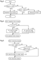
- the controller 31 determines whether the unseated state duration T1 is shorter than or equal to a specified unseated state determination time Tx in step S21.
- the unseated state determination time Tx can be set arbitrarily based on expected manners in which the unseated state occurs.
- the unseated state determination time Tx may be set arbitrarily as long as it is longer than the suspension time Td, and is, for example, 1 second or longer and 5 seconds or shorter, and preferably 1.5 seconds or longer and 3 seconds or shorter.
- the controller 31 performing the process of step S21 corresponds to an unseated state determining unit of the present embodiment.
- step S22 the process of step S22 is performed.
- the case in which the determination result in step S21 is affirmative corresponds to a case in which the unseated state duration T1 is determined to be shorter than or equal to the unseated state determination time Tx.
- step S22 the controller 31 sets the operation mode M to the limit mode M2. In this case, the controller 31 changes the operation mode M from the normal mode M1 to the limit mode M2.
- the controller 31 performing the process of step S22 corresponds to a limit setting unit of the present embodiment.
- step S23 the process of step S23 is performed.
- the case in which the determination result in step S21 is negative corresponds to a case in which the controller 31, which serves as the unseated state determining unit, determines that the unseated state duration T1 is longer than the unseated state determination time Tx.
- step S23 the controller 31 sets the operation mode M to the interruption mode M3. In this case, the controller 31 changes the operation mode M from the limit mode M2 to the interruption mode M3.
- the controller 31 performing the process of step S23 corresponds to an interruption setting unit of the present embodiment.
- step S22 or step S23 the controller 31 ends the unseated state process.
- step S3 determines whether the operation mode M is the normal mode M1.
- step S3 If the determination result in step S3 is affirmative, the controller 31 ends the travel controlling process while maintaining the operation mode M at the normal mode M1. That is, if the industrial vehicle 10 is traveling in the normal mode M1 with the driver state being the seated state, the travel in the normal mode M1 is continued.
- step S4 the process of step S4 is performed.
- the case in which the determination result in step S3 is negative corresponds to a case in which the operation mode M is set to the limit mode M2 or the interruption mode M3.
- a situation that corresponds to such a case includes, for example, a situation in which the limit mode M2 or the interruption mode M3 is set by the unseated state process in step S2 performed in the past, and is maintained.
- step S4 the controller 31 performs the returning process.
- the returning process is a process for setting, to the normal mode M1 again, the operation mode M that has been set to the limit mode M2 or the interruption mode M3. After the returning process ends, the controller 31 ends the travel controlling process and restarts the travel controlling process from step S1.
- the controller 31 determines whether the operation mode M is set to the limit mode M2 in step S41.
- step S42 in a case in which the operation mode M is set to the limit mode M2, the controller 31 sets the operation mode M to the normal mode M1 when the driver state detected by the driver detecting unit 36 becomes the seated state.
- the controller 31 changes the operation mode M from the limit mode M2 to the normal mode M1.
- the time at which the controller 31 changes the operation mode M from the limit mode M2 to the normal mode M1 is not limited to the time at which the driver detecting unit 36 detects the seated state.
- the controller 31 may change the operation mode M from the limit mode M2 to the normal mode M1 when a specified suspension time elapses after the driver detecting unit 36 detects the seated state.
- step S43 the controller 31 determines whether a specified cancellation condition is met.
- the cancellation condition is a condition that needs to be met in order to reset the operation mode M to the normal mode M1.
- the cancellation condition includes a condition in which the driver state is the seated state and a condition in which the direction detecting unit 35 has detected a change in an operation position.
- the condition in which the direction detecting unit 35 has detected a change in the operation position refers to a condition in which the operated direction of the direction instructing unit 17 has been changed.
- step S42 the controller 31 sets the operation mode M to the normal mode M1. If the controller 31 performs the process of step S42 in the returning process, the controller 31 changes the operation mode M from the interruption mode M3 to the normal mode M1 in step S42.
- step S43 If the determination result in step S43 is negative, that is, if the cancellation condition is not met, the controller 31 omits step S42 and ends the returning process. Therefore, the operation mode M is maintained at the interruption mode M3.
- the driver may become unseated from the driver's seat 15 while the industrial vehicle 10 is traveling in the normal mode M1.
- Such an unseated state occurs, for example, when the driver checks the surrounding situation.
- the cargo handling device 20 or a cargo mounted on the cargo handling device 20 may block the forward field of vision from the driver's seat 15. Therefore, even in a situation in which the industrial vehicle 10 is traveling, the driver may stand up from the driver's seat 15 in order to check the situation in front of the industrial vehicle 10.
- the driver detecting unit 36 detects that the driver state has become the unseated state. Accordingly, the determination result in step S1 is affirmative, and the unseated state process is performed in step S2.
- the unseated state duration T1 is shorter than or equal to the unseated state determination time Tx. Accordingly, the determination result in step S21 is affirmative, and the operation mode M is changed to the limit mode M2 in step S22. Specifically, the operation mode M is changed from the normal mode M1 to the limit mode M2. Thus, the target value of the rotation speed of the engine 51 transmitted from the controller 31 to the travel controller 73 is lower than that in the normal mode M1. Accordingly, the rotation speed of the engine 51 is reduced. At this time, the transmission of the driving force by the driving force transmitting mechanism 60 is not interrupted. Therefore, in the limit mode M2, the resistance of the engine 51 due to engine braking is transmitted to the driven wheels 12, 13 via the driving force transmitting mechanism 60 as in the normal mode M1.
- the controller 31 sets the operation mode M to the interruption mode M3 in step S23. Specifically, the controller 31 changes the operation mode M from the limit mode M2 to the interruption mode M3. Accordingly, the controller 31 stops energizing the solenoid of the electromagnetic valve 69 and interrupts the transmission of the driving force by the driving force transmitting mechanism 60. As a result, in the interruption mode M3, unlike the cases of the normal mode M1 or the limit mode M2, the resistance of the engine 51 due to engine braking is not transmitted to the driven wheels 12, 13.
- the present embodiment has the following advantages.
- the operation mode M includes the normal mode M1, the limit mode M2, which limits the driving force of the engine 51, and the interruption mode M3, which interrupts the transmission of the driving force by the driving force transmitting mechanism 60. If it is determined in step S21 that the unseated state duration T1 is shorter than or equal to the unseated state determination time Tx, the controller 31 performs the process of step S22 to set the operation mode M to the limit mode M2. If it is determined in step S21 that the unseated state duration T1 is longer than the unseated state determination time Tx, the controller 31 performs the process of step S23 to set the operation mode M to the interruption mode M3.
- the controller 31 sets the operation mode M to the limit mode M2 if the unseated state duration T1 is shorter than or equal to the unseated state determination time Tx.
- the driving force is limited without the transmission of the driving force being interrupted if the duration of the unseated state is short, that is, if the unseated state duration T1 is shorter than or equal to the unseated state determination time Tx.
- the operation mode M which has been set to the limit mode M2, is set to the interruption mode M3. Accordingly, the transmission of the driving force is interrupted after the driving force is limited in the limit mode M2.
- step S42 In a case in which the operation mode M is set to the limit mode M2, the controller 31 performs the process of step S42 to set the operation mode M to the normal mode M1 when the driver state detected by the driver detecting unit 36 becomes the seated state.
- the operation mode M returns to the normal mode M1 through a simple operation of, for example, the driver sitting on the driver's seat 15 again. Therefore, it is easy to return the operation mode M from the limit mode M2 to the normal mode M1.
- step S43 When the operation mode M is set to the interruption mode M3, the controller 31 determines whether the driver state is the seated state in step S43 and whether the direction detecting unit 35 has detected a change in the operated direction of the direction instructing unit 17. When the determination result in step S43 is affirmative, the controller 31 performs the process of step S42 to set the operation mode M to the normal mode M1.
- the operation mode M can be returned to the normal mode M1 not only when the driver is seated, but also when the driver indicates their intention to continue driving the industrial vehicle 10 by operating the direction instructing unit 17. This reduces the possibility that the operation mode M will be returned to the normal mode M1 without the driver's intention of driving the industrial vehicle 10, so the safety of the industrial vehicle 10 is improved.
- step S101 the controller 31 determines whether the industrial vehicle 10 is in a stopped state.
- the controller 31 performing the process of step S101 corresponds to a stopped state determining unit of the present embodiment.
- the controller 31 of the present embodiment determines whether the industrial vehicle 10 is in a stopped state based on the vehicle speed detected by the vehicle speed sensor 72. When the vehicle speed detected by the vehicle speed sensor 72 is greater than a specified speed threshold, the controller 31 determines that the industrial vehicle 10 is traveling. When the vehicle speed is lower than or equal to the speed threshold, the controller 31 determines that the industrial vehicle 10 is in a stopped state.
- the determination of whether the industrial vehicle 10 is traveling or in a stopped state is not limited to the method described above, and any method can be employed. For example, the controller 31 may perform the determination based on a detection result of the rotation speed sensor 54.
- step S23 the process of step S23 is performed.
- the case in which the determination result in step S101 is affirmative corresponds to a case in which the unseated state is detected while the industrial vehicle 10 is in a stopped state.
- step S23 the controller 31 sets the operation mode M to the interruption mode M3.
- the controller 31 changes the operation mode M from the normal mode M1 to the interruption mode M3.
- the controller 31 performing the processes of step S101 and step S23 corresponds to a forcible interruption unit of the present embodiment.
- step S101 determines whether the accelerator 16 is being operated. Whether the accelerator 16 is being operated is used as an index indicating whether the driver has an intention to drive the industrial vehicle 10.
- step S102 determines whether the accelerator 16 is not being operated. If the determination result in step S102 is negative, that is, if it is determined that the accelerator 16 is not being operated, the process of step S21 is performed. Thus, if the unseated state is detected in a situation in which the accelerator 16 is not being operated in the normal mode M1, the operation mode M is changed from the normal mode M1 to the limit mode M2 in step S22, or the operation mode M is changed from the normal mode M1 to the interruption mode M3 in step S23.
- step S102 determines whether the operation mode M is the normal mode M1.
- step S103 determines whether the operation mode M is the limit mode M2 or the interruption mode M3. If the determination result in step S103 is negative, that is, if the operation mode M is the limit mode M2 or the interruption mode M3, the process of step S21 is performed. In this manner, the controller 31 sets the operation mode M to the limit mode M2 or the interruption mode M3 in accordance with the unseated state duration T1.
- step S104 determines whether the unseated state duration T1 is shorter than or equal to the unseated state determination time Tx in step S104.
- step S23 In a case in which the determination result in step S104 is negative, the process of step S23 is performed.
- the case in which the determination result in step S104 is negative is, for example, a case in which the accelerator 16 has been operated for a period longer than the unseated state determination time Tx while the unseated state continues.
- the controller 31 sets the operation mode M to the interruption mode M3.
- step S105 the controller 31 continues the travel in the normal mode M1.
- the processes of Step S21 and Step S22 are omitted. Therefore, even in a case in which the unseated state is detected while the accelerator 16 is being operated in the normal mode M1, the controller 31 maintains the operation mode M at the normal mode M1 as long as the unseated state duration T1 is shorter than or equal to the unseated state determination time Tx.
- the controller 31 performing the processes of steps S103 to S105 corresponds to a travel continuing unit of the present embodiment.
- step S23 the controller 31 sets the operation mode M to the interruption mode M3.
- the controller 31 changes the operation mode M from the normal mode M1 to the interruption mode M3. Therefore, if the driver becomes unseated from the driver's seat 15 while the industrial vehicle 10 is in a stopped state, the controller 31 omits the limitation of the driving force in the limit mode M2 and interrupts the transmission of the driving force by the driving force transmitting mechanism 60.
- step S101 If the driver becomes unseated from the driver's seat 15 while the industrial vehicle 10 is traveling, the determination result in step S101 is negative, and the process of step S102 is performed. In this case, if the driver is operating the accelerator 16, the determination result in step S102 is affirmative, and the process of step S103 is performed. In this case, if the operation mode M is the normal mode M1, the determination result in step S103 is affirmative, and the process of step S105 is performed. In step S105, the controller 31 continues the traveling in the normal mode M1 even if the driver state is the unseated state.
- the second embodiment has the following advantages.
- step S101 in which it is determined whether the industrial vehicle 10 is in a stopped state
- step S23 in which the operation mode M is set to the interruption mode M3 if the unseated state is detected while the industrial vehicle 10 is in a stopped state.
- the operation mode M is set to the interruption mode M3 without performing the limit mode M2 even if the unseated state duration T1 is shorter than or equal to the unseated state determination time Tx.
- the interruption mode M3 since the transmission of the driving force by the driving force transmitting mechanism 60 is interrupted, creep does not occur. Therefore, it is possible to prevent the industrial vehicle 10 in a stopped state from moving due to creep while the driver is unseated from the driver's seat 15.
- step S105 If the unseated state is detected while the accelerator 16 is being operated in the normal mode M1, the controller 31 performs the process of step S105, in which the travel in the normal mode M1 is continued.
- the accelerator 16 If the accelerator 16 is being operated, there is a possibility that the driver has an intention to continue driving the industrial vehicle 10. Thus, even if the driver state is the unseated state, the driver can drive the industrial vehicle 10 in the normal mode M1 by operating the accelerator 16. Therefore, it is possible to further improve the driving comfort of the industrial vehicle 10 by reflecting the intention of the driver to continue driving the industrial vehicle 10.
- step S101 may be omitted.
- steps S102 to S105 may be omitted.
- step S41 may be omitted.
- the controller 31 executes the process of step S43 regardless of whether the operation mode M is the limit mode M2 or the interruption mode M3. Even in the case of the limit mode M2, the controller 31 sets the operation mode M to the normal mode M1 if the cancellation condition is met.
- the trigger for changing the operation mode M from the limit mode M2 to the normal mode M1 is not limited to the fact that the driver state detected by the driver detecting unit 36 becomes the seated state.
- the driver detecting unit 36 may be separate from or integrated with the controller 31.
- the driver detecting unit 36 may be a functioning unit that is implemented by the controller 31.
- the cancellation condition does not necessarily need to include a condition in which the driver state is the seated state and a condition in which the direction detecting unit 35 has detected a change in the operation position.
- the cancellation condition may be met when a cancellation button provided in the industrial vehicle 10 is operated.
- the trigger for performing the process of step S42 which sets the operation mode M to the normal mode M1 in a case in which the operation mode M is set to the limit mode M2, is not limited to the fact that the driver state becomes the seated state, but may be changed.
- the trigger may be the same as the cancellation condition in step S43.
- the normal mode M1 does not necessarily need to be defined explicitly.
- an operation mode M other than the limit mode M2 and the interruption mode M3 may be defined as the normal mode M1.
- the industrial vehicle 10 may include a seat belt, a buckle connected to the seat belt, and a seat belt use sensor.
- the seat belt, the buckle, and the seat belt use sensor are not shown in the drawings.
- the seat belt, the buckle, and the seat belt use sensor are attached to the driver's seat 15.
- the seat belt use sensor is configured to detect whether the driver is using the seat belt.
- the seat belt use sensor includes a switch.
- the switch of the seat belt use sensor is turned ON when the seat belt is fastened to the buckle, and is turned OFF when the seat belt is not fastened to the buckle.
- the specific configuration of the seat belt use sensor is arbitrary, and may include, for example, a pressure sensitive sensor, an optical sensor, or a camera.
- the driver detecting unit 36 may detect the driver state based on a detection result of the seat belt use sensor. For example, the driver detecting unit 36 determines that the driver state is the seated state in a case in which the seat belt use sensor is ON, and determines that the driver state is the unseated state in a case in which the seat belt use sensor is OFF.
- the driver detecting unit 36 may detect the driver state based on the detection result of the seat switch 18 and the detection result of the seat belt use sensor. For example, the driver detecting unit 36 determines that the driver state is the seated state in a case in which the seat belt use sensor is turned ON after the seat switch 18 is turned ON. This configuration promotes the driving of the industrial vehicle 10 with the seat belt being used properly.
- the driver detecting unit 36 determines that the driver state is the unseated state in a case in which the seat switch 18 is OFF, in a case in which the seat belt use sensor is OFF, or in a case in which the seat belt use sensor is turned ON before the seat switch 18 is turned ON.
- the case in which the seat belt use sensor is turned ON before the seat switch 18 is turned ON includes, for example, a case in which the seat belt is fastened to the buckle before the driver sits on the driver's seat 15.
- the information used by the driver detecting unit 36 to detect the driver state is not limited to the detection result of the seat switch 18, but may be changed.
- the industrial vehicle 10 is not limited to a forklift.
- the industrial vehicle 10 may be a towing tractor.
Landscapes
- Engineering & Computer Science (AREA)
- Automation & Control Theory (AREA)
- Transportation (AREA)
- Mechanical Engineering (AREA)
- Human Computer Interaction (AREA)
- Chemical & Material Sciences (AREA)
- Combustion & Propulsion (AREA)
- Forklifts And Lifting Vehicles (AREA)
- Auxiliary Drives, Propulsion Controls, And Safety Devices (AREA)
Abstract
Description
- The present disclosure relates to an industrial vehicle and a method for controlling an industrial vehicle.
-
Japanese Laid-Open Patent Publication No. 2006-316942 - A driver of an industrial vehicle may be temporarily unseated, for example, in order to check the surrounding situation during driving. However, in the above-described configuration, when an unseated state continues until the delay time elapses, the transmission of the driving force is interrupted. The operational feeling of the industrial vehicle during driving is changed by such interruption of the driving force transmission. As a change in the operational feeling increases, the driving comfort for the driver may be reduced significantly.
- This Summary is provided to introduce a selection of concepts in a simplified form that are further described below in the Detailed Description. This Summary is not intended to identify key features or essential features of the claimed subject matter, nor is it intended to be used as an aid in determining the scope of the claimed subject matter.
- In a general aspect, an industrial vehicle is provided that includes an engine, a driven wheel, a driving force transmitting mechanism configured to transmit a driving force of the engine to the driven wheel, a driver's seat on which a driver is seated, a driver detecting unit, and a controller. The driver detecting unit is configured to detect a driver state of driver states including an unseated state, in which the driver is unseated from the driver's seat, and a seated state, in which the driver is seated on the driver's seat. The controller is configured to set an operation mode of operation modes based on the driver state detected by the driver detecting unit. The operation modes include a normal mode, a limit mode that limits the driving force, and an interruption mode that interrupts a transmission of the driving force to the driven wheel by the driving force transmitting mechanism. The controller includes an unseated state determining unit, a limit setting unit, and an interruption setting unit. The unseated state determining unit is configured to determine, when the driver state is the unseated state, whether an unseated state duration, during which the unseated state continues, is shorter than or equal to a specified unseated state determination time. The limit setting unit is configured to set the operation mode to the limit mode when the unseated state determining unit determines that the unseated state duration is shorter than or equal to the unseated state determination time. The interruption setting unit is configured to set the operation mode to the interruption mode when the unseated state determining unit determines that the unseated state duration is longer than the unseated state determination time.
- Other features and aspects will be apparent from the following detailed description, the drawings, and the claims.
-
-
Fig. 1 is a perspective view of an entire industrial vehicle according to a first embodiment. -
Fig. 2 is a diagram showing a system configuration of the industrial vehicle according to the first embodiment. -
Fig. 3 is a flowchart showing a travel controlling process according to the first embodiment. -
Fig. 4 is a flowchart showing an unseated state process according to the first embodiment. -
Fig. 5 is a flowchart showing a returning process according to the first embodiment. -
Fig. 6 is a flowchart showing an unseated state process according to a second embodiment. - Throughout the drawings and the detailed description, the same reference numerals refer to the same elements. The drawings may not be to scale, and the relative size, proportions, and depiction of elements in the drawings may be exaggerated for clarity, illustration, and convenience.
- This description provides a comprehensive understanding of the methods, apparatuses, and/or systems described. Modifications and equivalents of the methods, apparatuses, and/or systems described are apparent to one of ordinary skill in the art. Sequences of operations are exemplary, and may be changed as apparent to one of ordinary skill in the art, with the exception of operations necessarily occurring in a certain order. Descriptions of functions and constructions that are well known to one of ordinary skill in the art may be omitted.
- Exemplary embodiments may have different forms, and are not limited to the examples described. However, the examples described are thorough and complete, and convey the full scope of the disclosure to one of ordinary skill in the art.
- In this specification, "at least one of A and B" should be understood to mean "only A, only B, or both A and B."
- An
industrial vehicle 10 according to a first embodiment will now be described. - As shown in
Fig. 1 , theindustrial vehicle 10 includes avehicle body 11, two drivenwheels wheels 14, a driver'sseat 15, and acargo handling device 20. Theindustrial vehicle 10 of the present embodiment is a counterbalance forklift. - The driven
wheels vehicle body 11. The two drivenwheels - The two steered
wheels 14 are provided in a rear lower part of thevehicle body 11. The two steeredwheels 14 are separated from each other in the vehicle width direction. - The driver's
seat 15 is a seat on which a driver sits. The driver'sseat 15 is provided in an upper part of thevehicle body 11. - The
cargo handling device 20 includes amast 21, twoforks 22, andlift cylinders 23. Themast 21 is provided in front of thevehicle body 11. Theforks 22 are lifted and lowered together with themast 21. A cargo is mounted on theforks 22. Thelift cylinders 23 include hydraulic cylinders. Thelift cylinders 23 are extended or retracted to lift or lower themast 21. Theforks 22 are lifted or lowered as themast 21 is lifted or lowered. Theindustrial vehicle 10 of the present embodiment performs a traveling operation and a cargo handling operation when operated by the driver. - As shown in
Fig. 2 , theindustrial vehicle 10 includes acontroller 31, anaccelerator 16, anaccelerator sensor 34, adirection instructing unit 17, adirection detecting unit 35, a seat switch 18, adriver detecting unit 36, atravel system 50, and abus 40. - The
controller 31 includes aprocessor 32 and amemory 33. Theprocessor 32 may include, for example, a central processing unit (CPU), a graphics processing unit (GPU), or a digital signal processor (DSP). Thememory 33 includes a random-access memory (RAM) and a read-only memory (ROM). Thememory 33 stores programs for operating theindustrial vehicle 10. Thememory 33 stores program codes or commands configured to cause theprocessor 32 to execute processes. Thememory 33, which is a computer-readable medium, includes any type of medium that is accessible by a general-purpose computer or a dedicated computer. Thecontroller 31 may include a hardware circuit such as an application specific integrated circuit (ASIC) and a field programmable gate array (FPGA). Thecontroller 31, which is processing circuitry, may include one or more processors that operate according to a computer program, one or more hardware circuits such as an ASIC and an FPGA, or a combination thereof. - The
accelerator 16 is operated by the driver when accelerating thevehicle body 11. Theaccelerator 16 instructs thecontroller 31 to accelerate theindustrial vehicle 10 in response to operation by the driver. Theaccelerator 16 is, for example, an accelerator pedal. Theaccelerator 16 may have any specific configuration, and may be a switch, a lever, a touch panel, or the like. - The
accelerator sensor 34 detects an accelerator operated amount, which is the operated amount of theaccelerator 16. Theaccelerator sensor 34 outputs an electric signal that corresponds to the accelerator operated amount to thecontroller 31. Thecontroller 31 acquires the accelerator operated amount based on the electric signal from theaccelerator sensor 34. - The
direction instructing unit 17 is used to instruct the traveling direction of thevehicle body 11 in accordance with an operated direction. The traveling direction of thevehicle body 11 is regarded as the traveling direction of theindustrial vehicle 10. Specifically, thedirection instructing unit 17 is a direction lever. The operated direction includes a direction instructing a forward movement and a direction instructing a reverse movement. Thedirection instructing unit 17 is configured to be operable in the direction instructing a forward movement or the direction instructing a reverse movement with reference to a neutral position. The specific configuration of thedirection instructing unit 17 is not limited to a direction bar, but may be a switch, a touch panel, or the like. - The
direction detecting unit 35 detects the operated direction of thedirection instructing unit 17. Thedirection detecting unit 35 is also referred to as a direction sensor. Thedirection detecting unit 35 detects whether thedirection instructing unit 17 is operated in the direction instructing a forward movement or the direction instructing a reverse movement with reference to the neutral position of thedirection instructing unit 17. Thedirection detecting unit 35 outputs an electric signal corresponding to the operated direction of thedirection instructing unit 17 to thecontroller 31. Thecontroller 31 acquires the operated direction of thedirection instructing unit 17 based on the electric signal from thedirection detecting unit 35. Thecontroller 31 recognizes whether a forward movement is instructed by the driver, whether a reverse movement is instructed by the driver, or whether neither is instructed by the driver. - The seat switch 18 is a mechanism that is turned ON when the driver is seated on the driver's
seat 15. The seat switch 18 is provided, for example, under the driver'sseat 15. The specific configuration of the seat switch 18 is not limited to a switch, but may be a pressure sensitive sensor, a weight sensor, an optical sensor, a camera, or the like. - The
driver detecting unit 36 is an electronic control unit that detects a driver state. The driver state includes an unseated state and a seated state. In the unseated state, the driver is not seated on the driver'sseat 15. In the seated state, the driver is seated on the driver'sseat 15. The driver state is detected based on a detection result of the seat switch 18. For example, when the seat switch 18 is ON, thedriver detecting unit 36 determines that the driver state is the seated state. When the seat switch 18 is OFF, thedriver detecting unit 36 determines that the driver state is the unseated state. - The method for detecting the driver state is not limited to the above described method, but may be any appropriate method. For example, when a weight sensor is used as a mechanism corresponding to the seat switch 18, the
driver detecting unit 36 determines that the driver state is the seated state if the weight detected by the weight sensor is greater than or equal to a specified value, and determines that the driver state is the unseated state if the weight detected by the weight sensor is less than the specified value. When a camera is used as a mechanism corresponding to the seat switch 18, thedriver detecting unit 36 may extract a specified feature quantity from an image captured by the camera and determine the driver state based on the feature quantity. Examples of the feature quantity include a positional relationship between the driver and the driver'sseat 15 in the image, the posture of the driver, and the like. - The
travel system 50 causes thevehicle body 11 to travel. Thetravel system 50 includes anengine 51, anoutput shaft 53, arotation speed sensor 54, a drivingforce transmitting mechanism 60, a differential 70, anaxle 71, avehicle speed sensor 72, and atravel controller 73. Theindustrial vehicle 10 is a vehicle having an engine. - The
engine 51 is a drive source for traveling operation and cargo handling operation of theindustrial vehicle 10. Theengine 51 of the present embodiment is a gasoline engine, which uses gasoline as fuel. Theengine 51 includes athrottle actuator 52. The fuel of theengine 51 is not limited to gasoline, and may be, for example, liquefied petroleum gas (LPG) or compressed natural gas (CNG). Theengine 51 is not limited to a gasoline engine, and may be a diesel engine, for example. - The
throttle actuator 52 adjusts a throttle opening degree. Thethrottle actuator 52 adjusts the throttle opening degree to adjust the amount of air supplied to theengine 51. Accordingly, the rotation speed of theengine 51 is controlled. - The
output shaft 53 is coupled to theengine 51. Theoutput shaft 53 rotates when driven by theengine 51. - The
rotation speed sensor 54 is provided at theoutput shaft 53. Therotation speed sensor 54 detects the rotation speed of theengine 51. The rotation speed of theengine 51 is also the rotation speed of theoutput shaft 53. Therotation speed sensor 54 outputs an electric signal corresponding to the rotation speed of theoutput shaft 53 to thetravel controller 73. - The driving
force transmitting mechanism 60 transmits the driving force of theengine 51 to the drivenwheels force transmitting mechanism 60 includes atorque converter 61, atransmission 62, and twoelectromagnetic valves 69. - The
torque converter 61 is coupled to theoutput shaft 53. The driving force of theengine 51 is transmitted to thetorque converter 61 via theoutput shaft 53. Thetorque converter 61 includes a pump and turbine that are coupled to theoutput shaft 53. In thetorque converter 61, the turbine is rotated by hydraulic oil discharged from the pump. - The
transmission 62 includes aninput shaft 63, aforward clutch 64, aforward gear train 65, a reverse clutch 66, areverse gear train 67, and anoutput shaft 68. - The
input shaft 63 is coupled to thetorque converter 61. The driving force is transmitted from thetorque converter 61 to thetransmission 62 via theinput shaft 63. - The
forward clutch 64 is provided at theinput shaft 63. Theforward gear train 65 is provided between theforward clutch 64 and theoutput shaft 68. Theforward clutch 64 is switched between an engaged state and a disengaged state. The engaged state is a state in which theinput shaft 63 and theforward gear train 65 are connected to each other. The disengaged state is a state in which theinput shaft 63 and theforward gear train 65 are disconnected from each other. When theforward clutch 64 connects theinput shaft 63 and theforward gear train 65 to each other, the driving force is transmitted from theinput shaft 63 to theforward gear train 65. The driving force transmitted to theforward gear train 65 is then transmitted to theoutput shaft 68. When theforward clutch 64 is connected to theforward gear train 65, the driving force of theengine 51 is transmitted to theoutput shaft 68. When theforward clutch 64 and theforward gear train 65 are disconnected from each other, the driving force is not transmitted from theinput shaft 63 to theforward gear train 65. - The reverse clutch 66 is provided at the
input shaft 63. Thereverse gear train 67 is provided between the reverse clutch 66 and theoutput shaft 68. The reverse clutch 66 is switched between an engaged state and a disengaged state. The engaged state is a state in which theinput shaft 63 and thereverse gear train 67 are connected to each other. The disengaged state is a state in which theinput shaft 63 and thereverse gear train 67 are disconnected from each other. When the reverse clutch 66 connects theinput shaft 63 and thereverse gear train 67 to each other, the driving force is transmitted from theinput shaft 63 to thereverse gear train 67. The driving force transmitted to thereverse gear train 67 is then transmitted to theoutput shaft 68. When the reverse clutch 66 is connected to thereverse gear train 67, the driving force of theengine 51 is transmitted to theoutput shaft 68. When the reverse clutch 66 and thereverse gear train 67 are disconnected from each other, the driving force is not transmitted from theinput shaft 63 to thereverse gear train 67. - The
forward clutch 64 and the reverse clutch 66 are hydraulic clutches. The hydraulic clutches may be wet multi-disc clutches. - The
output shaft 68 receives the driving force when the forward clutch 64 or the reverse clutch 66 is engaged. Theoutput shaft 68 is rotated by the driving force transmitted from the forward clutch 64 or the reverse clutch 66. - The two
electromagnetic valves 69 correspond to theforward clutch 64 and the reverse clutch 66, respectively. Theelectromagnetic valves 69 control supply and discharge of hydraulic oil to and from theforward clutch 64 and the reverse clutch 66. Theelectromagnetic valves 69 supply or discharge hydraulic oil in accordance with the amount of electricity supplied to the solenoids. Theclutches 64, 66 are respectively switched between the engaged state and the disengaged state of by supply and discharge of hydraulic oil by theelectromagnetic valves 69. When thedirection instructing unit 17 instructs a forward movement, theforward clutch 64 and theforward gear train 65 are connected to each other. When thedirection instructing unit 17 instructs a backward movement, the reverse clutch 66 and thereverse gear train 67 are connected to each other. When thedirection instructing unit 17 instructs a neutral state, that is, when thedirection instructing unit 17 is in the neutral position, theforward clutch 64 and the reverse clutch 66 are both disengaged. When one of theforward clutch 64 and the reverse clutch 66 is engaged, resistance is produced in theengine 51 due to engine braking. In contrast, when theforward clutch 64 and the reverse clutch 66 are both disengaged, no resistance is produced in theengine 51 due to engine braking. - The
electromagnetic valve 69 is configured to be controlled by thecontroller 31. Thecontroller 31 controls the amount of electricity to the solenoids in theelectromagnetic valves 69, thereby controlling supply and discharge of hydraulic oil by theelectromagnetic valve 69. - The differential 70 is coupled to the
output shaft 68. Theaxle 71 is coupled to the differential 70. The drivenwheels axle 71. Theaxle 71 rotates as theoutput shaft 68 rotates. Theindustrial vehicle 10 travels when the drivenwheels axle 71. When theforward clutch 64 and theforward gear train 65 are connected to each other, theindustrial vehicle 10 moves forward. When the reverse clutch 66 and thereverse gear train 67 are connected to each other, theindustrial vehicle 10 moves backward. - The
vehicle speed sensor 72 is a sensor for detecting a vehicle speed, that is, a moving speed of thevehicle body 11. The moving speed of thevehicle body 11 is regarded as the traveling speed of theindustrial vehicle 10. Thevehicle speed sensor 72 is provided, for example, at theoutput shaft 68 or theaxle 71. Thevehicle speed sensor 72 outputs a pulse signal corresponding to the vehicle speed to thetravel controller 73. - The
travel controller 73 is an engine control unit that controls theengine 51. The hardware configuration of thetravel controller 73 is, for example, similar to that of thecontroller 31. Thetravel controller 73 adjusts the throttle opening degree by controlling thethrottle actuator 52. The driving force of theengine 51 is adjusted by adjusting the throttle opening degree. Thetravel controller 73 controls theelectromagnetic valve 69 that switches theclutches 64, 66 between the engaged state and the disengaged state. Accordingly, theclutches 64, 66 is switched between the engaged state and the disengaged state. - The
travel controller 73 and thecontroller 31 are configured to obtain information from each other via thebus 40. Thecontroller 31 transmits a specified command signal via thebus 40. In this manner, thecontroller 31 controls theengine 51 via thetravel controller 73. The command signal is, for example, a target value of the torque or the rotation speed of theengine 51. The target value is determined, for example, in accordance with operation of theaccelerator 16. Thetravel controller 73 of the present embodiment controls thethrottle actuator 52 such that the rotation speed of theengine 51 detected by therotation speed sensor 54 becomes the target value. Accordingly, theengine 51 generates driving force. The driving force of theengine 51 accelerates theindustrial vehicle 10. Therefore, theaccelerator 16 is regarded as a device that instructs acceleration by the driving force of theengine 51 in response to operation by the driver. - Further, the
controller 31 is capable of acquiring the rotation speed of theengine 51 detected by therotation speed sensor 54 via thebus 40 and thetravel controller 73. - The
controller 31 sets the operation mode M based on the driver state detected by thedriver detecting unit 36. The operation mode M includes a normal mode M1, a limit mode M2, and an interruption mode M3. - The normal mode M1 is a mode in which the
industrial vehicle 10 travels in response to operation by the driver. In the normal mode M1, theindustrial vehicle 10 is accelerated in accordance with an operated amount of theaccelerator 16. That is, the normal mode M1 is an operation mode M in which acceleration of theindustrial vehicle 10 is controlled by operation of theaccelerator 16. In the normal mode M1, the solenoid of theelectromagnetic valve 69 is energized in response to operation of thedirection instructing unit 17. As a result, theelectromagnetic valve 69 supplies or discharges hydraulic oil in accordance with operation of thedirection instructing unit 17. The operation mode M when theindustrial vehicle 10 is activated, that is, the initial state of the operation mode M is the normal mode M1. - The limit mode M2 is a mode in which the driving force of the
engine 51 is limited. In the limit mode M2, thecontroller 31 limits the target value of the rotation speed of theengine 51 up to a specified limit value. Accordingly, acceleration of theindustrial vehicle 10 by theaccelerator 16 is limited. That is, the limit mode M2 is an operation mode M in which acceleration of theindustrial vehicle 10 by theaccelerator 16 is limited. The limit value is, for example, the rotation speed of theengine 51 during idling. Thecontroller 31 transmits the target value of the rotation speed to thetravel controller 73. When the target value that corresponds to the operated amount of theaccelerator 16 is greater than the limit value, thecontroller 31 sets the target value of the rotation speed to the limit value. Thetravel controller 73 controls theengine 51 such that the rotation speed of theengine 51 becomes the target value transmitted from thecontroller 31. - The target value of the rotation speed of the
engine 51 may be set to the limit value in the normal mode M1. In this case, the limit value in the limit mode M2 is less than the limit value in the normal mode M1. The limit mode M2 is an operation mode M in which the limit value of the rotation speed of theengine 51 is less than that in the normal mode M1. In other words, the normal mode M1 is an operation mode M in which the limit value is greater than that in the limit mode M2. - In the limit mode M2, the solenoid of the
electromagnetic valve 69 is energized in response to operation of thedirection instructing unit 17. As a result, theelectromagnetic valve 69 supplies or discharges hydraulic oil in accordance with operation of thedirection instructing unit 17. - The interruption mode M3 is a mode in which the transmission of the driving force to the driven
wheels force transmitting mechanism 60 is interrupted. In the interruption mode M3, thecontroller 31 stops energizing the solenoid of theelectromagnetic valve 69. Accordingly, the supply of hydraulic oil to theclutches 64, 66 is stopped. Therefore, unlike the normal mode M1 or the limit mode M2, theclutches 64, 66 are both disengaged in the interruption mode M3 regardless of the operated direction of thedirection instructing unit 17. When theclutches 64, 66 are both disengaged, the driving force from theengine 51 to the drivenwheels force transmitting mechanism 60. Accordingly, in the interruption mode M3, the driving force is not transmitted from theengine 51 to the drivenwheels engine 51 is running. The interruption mode M3 is thus an operation mode M in which theindustrial vehicle 10 cannot be accelerated by operation of theaccelerator 16. In the interruption mode M3, since the transmission of the driving force by the drivingforce transmitting mechanism 60 is interrupted, creep does not occur. - The
controller 31 performs a travel controlling process for controlling the travel of theindustrial vehicle 10 based on the operation mode M. One example of the travel controlling process will now be described. The travel controlling process of the present embodiment is repeatedly performed while theindustrial vehicle 10 is activated. - As shown in
Fig. 3 , thecontroller 31 determines whether the driver state is the unseated state in step S1. This determination is made based on, for example, a detection result of thedriver detecting unit 36. - If the determination result in step S1 is affirmative, that is, if the driver state is the unseated state, the process of step S2 is performed. In step S2, the
controller 31 performs an unseated state process. The unseated state process is a process for setting the operation mode M when the driver state is the unseated state. After the unseated state process ends, thecontroller 31 ends the travel controlling process and restarts the travel controlling process from step S1. - The
controller 31 of the present embodiment performs the unseated state process when an unseated state duration T1 becomes longer than or equal to a specified suspension time Td. The unseated state duration T1 is a period during which the unseated state continues. Specifically, the unseated state duration T1 is a time period during which the unseated state continues from the time at which thedriver detecting unit 36 detects the unseated state. The suspension time Td may be set freely. For example, the suspension time Td is 0.5 seconds or shorter, preferably 0.2 seconds or shorter. When the unseated state duration T1 is shorter than the suspension time Td, thecontroller 31 omits the unseated state process and ends the travel controlling process. - An example of the unseated state process in step S2 will now be described.
- As shown in
Fig. 4 , thecontroller 31 determines whether the unseated state duration T1 is shorter than or equal to a specified unseated state determination time Tx in step S21. The unseated state determination time Tx can be set arbitrarily based on expected manners in which the unseated state occurs. The unseated state determination time Tx may be set arbitrarily as long as it is longer than the suspension time Td, and is, for example, 1 second or longer and 5 seconds or shorter, and preferably 1.5 seconds or longer and 3 seconds or shorter. Thecontroller 31 performing the process of step S21 corresponds to an unseated state determining unit of the present embodiment. - In a case in which the determination result in step S21 is affirmative, the process of step S22 is performed. The case in which the determination result in step S21 is affirmative corresponds to a case in which the unseated state duration T1 is determined to be shorter than or equal to the unseated state determination time Tx. In step S22, the
controller 31 sets the operation mode M to the limit mode M2. In this case, thecontroller 31 changes the operation mode M from the normal mode M1 to the limit mode M2. Thecontroller 31 performing the process of step S22 corresponds to a limit setting unit of the present embodiment. - In a case in which the determination result in step S21 is negative, the process of step S23 is performed. The case in which the determination result in step S21 is negative corresponds to a case in which the
controller 31, which serves as the unseated state determining unit, determines that the unseated state duration T1 is longer than the unseated state determination time Tx. In step S23, thecontroller 31 sets the operation mode M to the interruption mode M3. In this case, thecontroller 31 changes the operation mode M from the limit mode M2 to the interruption mode M3. Thecontroller 31 performing the process of step S23 corresponds to an interruption setting unit of the present embodiment. - After the process of step S22 or step S23, the
controller 31 ends the unseated state process. - If the determination result in step S1 is negative, that is, if the driver state is the seated state, the process of step S3 is performed as shown in
Fig. 3 . In step S3, thecontroller 31 determines whether the operation mode M is the normal mode M1. - If the determination result in step S3 is affirmative, the
controller 31 ends the travel controlling process while maintaining the operation mode M at the normal mode M1. That is, if theindustrial vehicle 10 is traveling in the normal mode M1 with the driver state being the seated state, the travel in the normal mode M1 is continued. - In a case in which the determination result in step S3 is negative, the process of step S4 is performed. The case in which the determination result in step S3 is negative corresponds to a case in which the operation mode M is set to the limit mode M2 or the interruption mode M3. A situation that corresponds to such a case includes, for example, a situation in which the limit mode M2 or the interruption mode M3 is set by the unseated state process in step S2 performed in the past, and is maintained. In step S4, the
controller 31 performs the returning process. The returning process is a process for setting, to the normal mode M1 again, the operation mode M that has been set to the limit mode M2 or the interruption mode M3. After the returning process ends, thecontroller 31 ends the travel controlling process and restarts the travel controlling process from step S1. - An example of the returning process in step S4 will now be described.
- As shown in
Fig. 5 , thecontroller 31 determines whether the operation mode M is set to the limit mode M2 in step S41. - If the determination result in step S41 is affirmative, that is, if the operation mode M is set to the limit mode M2, the process of step S42 is performed. In step S42, in a case in which the operation mode M is set to the limit mode M2, the
controller 31 sets the operation mode M to the normal mode M1 when the driver state detected by thedriver detecting unit 36 becomes the seated state. In order to perform the process of step S42 in the present embodiment, it suffices if the driver state is switched from the unseated state to the seated state, and theaccelerator 16 or thedirection instructing unit 17 does not necessarily need to be operated. In this case, thecontroller 31 changes the operation mode M from the limit mode M2 to the normal mode M1. - The time at which the
controller 31 changes the operation mode M from the limit mode M2 to the normal mode M1 is not limited to the time at which thedriver detecting unit 36 detects the seated state. For example, thecontroller 31 may change the operation mode M from the limit mode M2 to the normal mode M1 when a specified suspension time elapses after thedriver detecting unit 36 detects the seated state. - If the determination result in step S41 is negative, that is, if the operation mode M is set to the interruption mode M3, the process of step S43 is performed. In step S43, the
controller 31 determines whether a specified cancellation condition is met. The cancellation condition is a condition that needs to be met in order to reset the operation mode M to the normal mode M1. The cancellation condition includes a condition in which the driver state is the seated state and a condition in which thedirection detecting unit 35 has detected a change in an operation position. The condition in which thedirection detecting unit 35 has detected a change in the operation position refers to a condition in which the operated direction of thedirection instructing unit 17 has been changed. - In a case in which the determination result in step S43 is affirmative, that is, in a case in which the cancellation condition is met, the process of step S42 is performed. The case in which the cancellation condition is met includes a case in which the driver state is the seated state and the
direction detecting unit 35 has detected a change in the operation position. In step S42, thecontroller 31 sets the operation mode M to the normal mode M1. If thecontroller 31 performs the process of step S42 in the returning process, thecontroller 31 changes the operation mode M from the interruption mode M3 to the normal mode M1 in step S42. - If the determination result in step S43 is negative, that is, if the cancellation condition is not met, the
controller 31 omits step S42 and ends the returning process. Therefore, the operation mode M is maintained at the interruption mode M3. - Operation of the present embodiment will now be described.
- The driver may become unseated from the driver's
seat 15 while theindustrial vehicle 10 is traveling in the normal mode M1. Such an unseated state occurs, for example, when the driver checks the surrounding situation. Particularly, in theindustrial vehicle 10 such as a forklift, thecargo handling device 20 or a cargo mounted on thecargo handling device 20 may block the forward field of vision from the driver'sseat 15. Therefore, even in a situation in which theindustrial vehicle 10 is traveling, the driver may stand up from the driver'sseat 15 in order to check the situation in front of theindustrial vehicle 10. In this case, thedriver detecting unit 36 detects that the driver state has become the unseated state. Accordingly, the determination result in step S1 is affirmative, and the unseated state process is performed in step S2. - At least immediately after the driver becomes unseated from the driver's
seat 15, the unseated state duration T1 is shorter than or equal to the unseated state determination time Tx. Accordingly, the determination result in step S21 is affirmative, and the operation mode M is changed to the limit mode M2 in step S22. Specifically, the operation mode M is changed from the normal mode M1 to the limit mode M2. Thus, the target value of the rotation speed of theengine 51 transmitted from thecontroller 31 to thetravel controller 73 is lower than that in the normal mode M1. Accordingly, the rotation speed of theengine 51 is reduced. At this time, the transmission of the driving force by the drivingforce transmitting mechanism 60 is not interrupted. Therefore, in the limit mode M2, the resistance of theengine 51 due to engine braking is transmitted to the drivenwheels force transmitting mechanism 60 as in the normal mode M1. - If the driver continues being unseated after the operation mode M is set to the limit mode M2, the unseated state duration T1 becomes longer than the unseated state determination time Tx. In this case, the determination result in step S21 is negative. The
controller 31 thus sets the operation mode M to the interruption mode M3 in step S23. Specifically, thecontroller 31 changes the operation mode M from the limit mode M2 to the interruption mode M3. Accordingly, thecontroller 31 stops energizing the solenoid of theelectromagnetic valve 69 and interrupts the transmission of the driving force by the drivingforce transmitting mechanism 60. As a result, in the interruption mode M3, unlike the cases of the normal mode M1 or the limit mode M2, the resistance of theengine 51 due to engine braking is not transmitted to the drivenwheels - The present embodiment has the following advantages.
- (1-1) The operation mode M includes the normal mode M1, the limit mode M2, which limits the driving force of the
engine 51, and the interruption mode M3, which interrupts the transmission of the driving force by the drivingforce transmitting mechanism 60. If it is determined in step S21 that the unseated state duration T1 is shorter than or equal to the unseated state determination time Tx, thecontroller 31 performs the process of step S22 to set the operation mode M to the limit mode M2. If it is determined in step S21 that the unseated state duration T1 is longer than the unseated state determination time Tx, thecontroller 31 performs the process of step S23 to set the operation mode M to the interruption mode M3. - With this configuration, even if the driver becomes unseated from the driver's
seat 15 so that the driver state is the unseated state, thecontroller 31 sets the operation mode M to the limit mode M2 if the unseated state duration T1 is shorter than or equal to the unseated state determination time Tx. At this time, the driving force is limited without the transmission of the driving force being interrupted if the duration of the unseated state is short, that is, if the unseated state duration T1 is shorter than or equal to the unseated state determination time Tx. If the unseated state continues after the operation mode M is set to the limit mode M2 so that the unseated state duration T1 becomes longer than the unseated state determination time Tx, the operation mode M, which has been set to the limit mode M2, is set to the interruption mode M3. Accordingly, the transmission of the driving force is interrupted after the driving force is limited in the limit mode M2. - As a result, a change in the operational feeling of the
industrial vehicle 10 due to the driver becoming unseated from the driver'sseat 15 is reduced as compared to a case in which the operation mode M, which has been set to the normal mode M1, is set to the interruption mode M3 without being set to the limit mode M2. As such, the driving comfort of theindustrial vehicle 10 is prevented from being reduced. - (1-2) In a case in which the operation mode M is set to the limit mode M2, the
controller 31 performs the process of step S42 to set the operation mode M to the normal mode M1 when the driver state detected by thedriver detecting unit 36 becomes the seated state. - With this configuration, even in a case in which the operation mode M is set to the limit mode M2, the operation mode M returns to the normal mode M1 through a simple operation of, for example, the driver sitting on the driver's
seat 15 again. Therefore, it is easy to return the operation mode M from the limit mode M2 to the normal mode M1. - (1-3) When the operation mode M is set to the interruption mode M3, the
controller 31 determines whether the driver state is the seated state in step S43 and whether thedirection detecting unit 35 has detected a change in the operated direction of thedirection instructing unit 17. When the determination result in step S43 is affirmative, thecontroller 31 performs the process of step S42 to set the operation mode M to the normal mode M1. - With this configuration, when the transmission of the driving force is interrupted in the interruption mode M3, the driver needs to sit on the driver's
seat 15 in order to return the operation mode M to the normal mode M1. In addition to this, in order to return the operation mode M to the normal mode M1, it is necessary to change the operation position by operating thedirection instructing unit 17. Thus, the operation mode M can be returned to the normal mode M1 not only when the driver is seated, but also when the driver indicates their intention to continue driving theindustrial vehicle 10 by operating thedirection instructing unit 17. This reduces the possibility that the operation mode M will be returned to the normal mode M1 without the driver's intention of driving theindustrial vehicle 10, so the safety of theindustrial vehicle 10 is improved. - An
industrial vehicle 10 according to a second embodiment will now be described. The same reference numerals are given to those components in the second embodiment that are the same as the corresponding components of the first embodiment, and redundant explanations may be omitted. - As shown in
Fig. 6 , part of the sequence of the unseated state process is different between the first embodiment and the second embodiment. One example of the unseated state process according to the second embodiment will now be described. - In step S101, the
controller 31 determines whether theindustrial vehicle 10 is in a stopped state. Thecontroller 31 performing the process of step S101 corresponds to a stopped state determining unit of the present embodiment. Thecontroller 31 of the present embodiment determines whether theindustrial vehicle 10 is in a stopped state based on the vehicle speed detected by thevehicle speed sensor 72. When the vehicle speed detected by thevehicle speed sensor 72 is greater than a specified speed threshold, thecontroller 31 determines that theindustrial vehicle 10 is traveling. When the vehicle speed is lower than or equal to the speed threshold, thecontroller 31 determines that theindustrial vehicle 10 is in a stopped state. The determination of whether theindustrial vehicle 10 is traveling or in a stopped state is not limited to the method described above, and any method can be employed. For example, thecontroller 31 may perform the determination based on a detection result of therotation speed sensor 54. - In a case in which the determination result in step S101 is affirmative, the process of step S23 is performed. The case in which the determination result in step S101 is affirmative corresponds to a case in which the unseated state is detected while the
industrial vehicle 10 is in a stopped state. In step S23, thecontroller 31 sets the operation mode M to the interruption mode M3. In this case, thecontroller 31 changes the operation mode M from the normal mode M1 to the interruption mode M3. Thecontroller 31 performing the processes of step S101 and step S23 corresponds to a forcible interruption unit of the present embodiment. - If the determination result in step S101 is negative, that is, if it is determined that the
industrial vehicle 10 is traveling, the process of step S102 is performed. In step S102, thecontroller 31 determines whether theaccelerator 16 is being operated. Whether theaccelerator 16 is being operated is used as an index indicating whether the driver has an intention to drive theindustrial vehicle 10. - If the determination result in step S102 is negative, that is, if it is determined that the
accelerator 16 is not being operated, the process of step S21 is performed. Thus, if the unseated state is detected in a situation in which theaccelerator 16 is not being operated in the normal mode M1, the operation mode M is changed from the normal mode M1 to the limit mode M2 in step S22, or the operation mode M is changed from the normal mode M1 to the interruption mode M3 in step S23. - If the determination result in step S102 is affirmative, that is, if the
accelerator 16 is being operated, the process of step S103 is performed. In step S103, thecontroller 31 determines whether the operation mode M is the normal mode M1. - If the determination result in step S103 is negative, that is, if the operation mode M is the limit mode M2 or the interruption mode M3, the process of step S21 is performed. In this manner, the
controller 31 sets the operation mode M to the limit mode M2 or the interruption mode M3 in accordance with the unseated state duration T1. - In a case in which the determination result in step S103 is affirmative, the process of step S104 is performed. The case in which the determination result in step S103 is affirmative corresponds to a case in which the unseated state is detected while the
accelerator 16 is being operated in the normal mode M1. Thecontroller 31 determines whether the unseated state duration T1 is shorter than or equal to the unseated state determination time Tx in step S104. - In a case in which the determination result in step S104 is negative, the process of step S23 is performed. The case in which the determination result in step S104 is negative is, for example, a case in which the
accelerator 16 has been operated for a period longer than the unseated state determination time Tx while the unseated state continues. In this case, thecontroller 31 sets the operation mode M to the interruption mode M3. Thus, it is possible to prevent theindustrial vehicle 10 from traveling in the normal mode M1 for a long period of time while the unseated state continues. - In a case in which the determination result in step S104 is affirmative, the process of step S105 is performed. In step S105, the
controller 31 continues the travel in the normal mode M1. In this case, the processes of Step S21 and Step S22 are omitted. Therefore, even in a case in which the unseated state is detected while theaccelerator 16 is being operated in the normal mode M1, thecontroller 31 maintains the operation mode M at the normal mode M1 as long as the unseated state duration T1 is shorter than or equal to the unseated state determination time Tx. Thecontroller 31 performing the processes of steps S103 to S105 corresponds to a travel continuing unit of the present embodiment. - When the driver becomes unseated from the driver's
seat 15 even if theindustrial vehicle 10 is in a stopped state in the normal mode M1, the determination result in step S101 is affirmative, and the process of step S23 is performed. In step S23, thecontroller 31 sets the operation mode M to the interruption mode M3. In this case, thecontroller 31 changes the operation mode M from the normal mode M1 to the interruption mode M3. Therefore, if the driver becomes unseated from the driver'sseat 15 while theindustrial vehicle 10 is in a stopped state, thecontroller 31 omits the limitation of the driving force in the limit mode M2 and interrupts the transmission of the driving force by the drivingforce transmitting mechanism 60. - If the driver becomes unseated from the driver's
seat 15 while theindustrial vehicle 10 is traveling, the determination result in step S101 is negative, and the process of step S102 is performed. In this case, if the driver is operating theaccelerator 16, the determination result in step S102 is affirmative, and the process of step S103 is performed. In this case, if the operation mode M is the normal mode M1, the determination result in step S103 is affirmative, and the process of step S105 is performed. In step S105, thecontroller 31 continues the traveling in the normal mode M1 even if the driver state is the unseated state. - The second embodiment has the following advantages.
- (2-1) The
controller 31 performs the process of step S101, in which it is determined whether theindustrial vehicle 10 is in a stopped state, and the process of step S23, in which the operation mode M is set to the interruption mode M3 if the unseated state is detected while theindustrial vehicle 10 is in a stopped state. - With this configuration, in a case in which the
industrial vehicle 10 is in a stopped state, the operation mode M is set to the interruption mode M3 without performing the limit mode M2 even if the unseated state duration T1 is shorter than or equal to the unseated state determination time Tx. In the interruption mode M3, since the transmission of the driving force by the drivingforce transmitting mechanism 60 is interrupted, creep does not occur. Therefore, it is possible to prevent theindustrial vehicle 10 in a stopped state from moving due to creep while the driver is unseated from the driver'sseat 15. - (2-2) If the unseated state is detected while the
accelerator 16 is being operated in the normal mode M1, thecontroller 31 performs the process of step S105, in which the travel in the normal mode M1 is continued. - If the
accelerator 16 is being operated, there is a possibility that the driver has an intention to continue driving theindustrial vehicle 10. Thus, even if the driver state is the unseated state, the driver can drive theindustrial vehicle 10 in the normal mode M1 by operating theaccelerator 16. Therefore, it is possible to further improve the driving comfort of theindustrial vehicle 10 by reflecting the intention of the driver to continue driving theindustrial vehicle 10. - The above-described embodiments may be modified as described below. The above-described embodiments and the following modifications can be combined as long as the combined modifications remain technically consistent with each other.
- The travel controlling processes described in the first and second embodiments are merely examples, and the present disclosure is not limited to these. For example, in the second embodiment, the process of step S101 may be omitted. Likewise, in the second embodiment, the processes of steps S102 to S105 may be omitted.
- In the first and second embodiments, the process of step S41 may be omitted. In this case, for example, the
controller 31 executes the process of step S43 regardless of whether the operation mode M is the limit mode M2 or the interruption mode M3. Even in the case of the limit mode M2, thecontroller 31 sets the operation mode M to the normal mode M1 if the cancellation condition is met. - In other words, the trigger for changing the operation mode M from the limit mode M2 to the normal mode M1 is not limited to the fact that the driver state detected by the
driver detecting unit 36 becomes the seated state. - The
driver detecting unit 36 may be separate from or integrated with thecontroller 31. Thedriver detecting unit 36 may be a functioning unit that is implemented by thecontroller 31. - In the first and second embodiments, the cancellation condition does not necessarily need to include a condition in which the driver state is the seated state and a condition in which the
direction detecting unit 35 has detected a change in the operation position. For example, the cancellation condition may be met when a cancellation button provided in theindustrial vehicle 10 is operated. - In the first and second embodiments, the trigger for performing the process of step S42, which sets the operation mode M to the normal mode M1 in a case in which the operation mode M is set to the limit mode M2, is not limited to the fact that the driver state becomes the seated state, but may be changed. For example, the trigger may be the same as the cancellation condition in step S43.
- In the first and second embodiments, the normal mode M1 does not necessarily need to be defined explicitly. For example, an operation mode M other than the limit mode M2 and the interruption mode M3 may be defined as the normal mode M1.
- In the first and second embodiments, the
industrial vehicle 10 may include a seat belt, a buckle connected to the seat belt, and a seat belt use sensor. The seat belt, the buckle, and the seat belt use sensor are not shown in the drawings. The seat belt, the buckle, and the seat belt use sensor are attached to the driver'sseat 15. - The seat belt use sensor is configured to detect whether the driver is using the seat belt. For example, the seat belt use sensor includes a switch. For example, the switch of the seat belt use sensor is turned ON when the seat belt is fastened to the buckle, and is turned OFF when the seat belt is not fastened to the buckle. The specific configuration of the seat belt use sensor is arbitrary, and may include, for example, a pressure sensitive sensor, an optical sensor, or a camera.
- The
driver detecting unit 36 may detect the driver state based on a detection result of the seat belt use sensor. For example, thedriver detecting unit 36 determines that the driver state is the seated state in a case in which the seat belt use sensor is ON, and determines that the driver state is the unseated state in a case in which the seat belt use sensor is OFF. - Further, the
driver detecting unit 36 may detect the driver state based on the detection result of the seat switch 18 and the detection result of the seat belt use sensor. For example, thedriver detecting unit 36 determines that the driver state is the seated state in a case in which the seat belt use sensor is turned ON after the seat switch 18 is turned ON. This configuration promotes the driving of theindustrial vehicle 10 with the seat belt being used properly. - On the other hand, the
driver detecting unit 36 determines that the driver state is the unseated state in a case in which the seat switch 18 is OFF, in a case in which the seat belt use sensor is OFF, or in a case in which the seat belt use sensor is turned ON before the seat switch 18 is turned ON. The case in which the seat belt use sensor is turned ON before the seat switch 18 is turned ON includes, for example, a case in which the seat belt is fastened to the buckle before the driver sits on the driver'sseat 15. - The information used by the
driver detecting unit 36 to detect the driver state is not limited to the detection result of the seat switch 18, but may be changed. - In the first and second embodiments, the
industrial vehicle 10 is not limited to a forklift. For example, theindustrial vehicle 10 may be a towing tractor. - Various changes in form and details may be made to the examples above without departing from the spirit and scope of the claims and their equivalents. The examples are for the sake of description only, and not for purposes of limitation. Descriptions of features in each example are to be considered as being applicable to similar features or aspects in other examples. Suitable results may be achieved if sequences are performed in a different order, and/or if components in a described system, architecture, device, or circuit are combined differently, and/or replaced or supplemented by other components or their equivalents. The scope of the disclosure is not defined by the detailed description, but by the claims and their equivalents. All variations within the scope of the claims and their equivalents are included in the disclosure.
Claims (6)
- An industrial vehicle (10), comprising:an engine (51);a driven wheel (12, 13);a driving force transmitting mechanism (60) configured to transmit a driving force of the engine (51) to the driven wheel (12, 13);a driver's seat (15) on which a driver is seated;a driver detecting unit (36) configured to detect a driver state of driver states including an unseated state, in which the driver is unseated from the driver's seat (15), and a seated state, in which the driver is seated on the driver's seat (15); anda controller (31) configured to set an operation mode of operation modes based on the driver state detected by the driver detecting unit (36), whereinthe operation modes include a normal mode, a limit mode that limits the driving force, and an interruption mode that interrupts a transmission of the driving force to the driven wheel (12, 13) by the driving force transmitting mechanism (60), andthe controller (31) includes:an unseated state determining unit configured to determine, when the driver state is the unseated state, whether an unseated state duration, during which the unseated state continues, is shorter than or equal to a specified unseated state determination time;a limit setting unit configured to set the operation mode to the limit mode when the unseated state determining unit determines that the unseated state duration is shorter than or equal to the unseated state determination time; andan interruption setting unit configured to set the operation mode to the interruption mode when the unseated state determining unit determines that the unseated state duration is longer than the unseated state determination time.
- The industrial vehicle (10) according to claim 1, wherein the controller (31) is configured to set, in a case in which the operation mode is set to the limit mode, the operation mode to the normal mode when the driver state detected by the driver detecting unit (36) becomes the seated state.
- The industrial vehicle (10) according to claim 1 or 2, further comprising:a direction instructing unit (17) that instructs a traveling direction of the industrial vehicle (10) in accordance with an operated direction; anda direction detecting unit (35) that detects the operated direction,wherein the controller (31) is configured to set, when the operation mode is set to the interruption mode, the operation mode to the normal mode when the driver state is the seated state and the direction detecting unit (35) detects a change in the operated direction.
- The industrial vehicle (10) according to any one of claims 1 to 3,
wherein the controller (31) includes:a stopped state determining unit configured to determine whether the industrial vehicle (10) is in a stopped state; anda forcible interruption unit configured to set the operation mode to the interruption mode when the unseated state is detected while the industrial vehicle (10) is in a stopped state. - The industrial vehicle (10) according to any one of claims 1 to 4, further comprising an accelerator (16) that instructs acceleration by the driving force in response to operation by the driver,
wherein the controller (31) includes a travel continuing unit that is configured to continue a travel in the normal mode if the unseated state is detected while the accelerator (16) is being operated in the normal mode. - A method for controlling an industrial vehicle (10), the industrial vehicle (10) including an engine (51), a driven wheel (12, 13), a driving force transmitting mechanism (60) configured to transmit a driving force of the engine (51) to the driven wheel (12, 13), and a driver's seat (15) on which a driver is seated, the method comprising:detecting a driver state of driver states including an unseated state, in which the driver is unseated from the driver's seat (15), and a seated state, in which the driver is seated on the driver's seat (15); andsetting an operation mode of operation modes based on the detected driver state, whereinthe operation modes include a normal mode, a limit mode that limits the driving force, and an interruption mode that interrupts a transmission of the driving force to the driven wheel (12, 13) by the driving force transmitting mechanism (60), andthe setting the operation mode includes:determining, when the driver state is the unseated state, whether an unseated state duration, during which the unseated state continues, is shorter than or equal to a specified unseated state determination time;setting the operation mode to the limit mode when the unseated state duration is determined to be shorter than or equal to the unseated state determination time; andsetting the operation mode to the interruption mode when the unseated state duration is determined to be longer than the unseated state determination time.
Applications Claiming Priority (1)
| Application Number | Priority Date | Filing Date | Title |
|---|---|---|---|
| JP2021207137A JP7626055B2 (en) | 2021-12-21 | 2021-12-21 | Industrial Vehicles |
Publications (2)
| Publication Number | Publication Date |
|---|---|
| EP4201774A1 true EP4201774A1 (en) | 2023-06-28 |
| EP4201774B1 EP4201774B1 (en) | 2025-06-18 |
Family
ID=84537103
Family Applications (1)
| Application Number | Title | Priority Date | Filing Date |
|---|---|---|---|
| EP22213778.8A Active EP4201774B1 (en) | 2021-12-21 | 2022-12-15 | Industrial vehicle and method for controlling industrial vehicle |
Country Status (2)
| Country | Link |
|---|---|
| EP (1) | EP4201774B1 (en) |
| JP (1) | JP7626055B2 (en) |
Families Citing this family (1)
| Publication number | Priority date | Publication date | Assignee | Title |
|---|---|---|---|---|
| WO2025009170A1 (en) * | 2023-07-06 | 2025-01-09 | 富士通株式会社 | Safe driving evaluation program, method, and device |
Citations (4)
| Publication number | Priority date | Publication date | Assignee | Title |
|---|---|---|---|---|
| US20040089491A1 (en) * | 2002-11-07 | 2004-05-13 | Visteon Global Technologies, Inc. | Creep torque command interrupt for HEVs and EVs |
| US20060254847A1 (en) * | 2005-05-13 | 2006-11-16 | Michihiro Miura | Industrial vehicle |
| US20150034424A1 (en) * | 2012-04-23 | 2015-02-05 | Komatsu Ltd. | Engine-powered forklift truck and method of releasing load handling interlock thereof |
| EP3006251A1 (en) * | 2013-05-07 | 2016-04-13 | Bosch Automotive Products (Suzhou) Co., Ltd. | Vehicle driving force control unit, control system and method, and vehicle |
-
2021
- 2021-12-21 JP JP2021207137A patent/JP7626055B2/en active Active
-
2022
- 2022-12-15 EP EP22213778.8A patent/EP4201774B1/en active Active
Patent Citations (5)
| Publication number | Priority date | Publication date | Assignee | Title |
|---|---|---|---|---|
| US20040089491A1 (en) * | 2002-11-07 | 2004-05-13 | Visteon Global Technologies, Inc. | Creep torque command interrupt for HEVs and EVs |
| US20060254847A1 (en) * | 2005-05-13 | 2006-11-16 | Michihiro Miura | Industrial vehicle |
| JP2006316942A (en) | 2005-05-13 | 2006-11-24 | Toyota Industries Corp | Industrial vehicle |
| US20150034424A1 (en) * | 2012-04-23 | 2015-02-05 | Komatsu Ltd. | Engine-powered forklift truck and method of releasing load handling interlock thereof |
| EP3006251A1 (en) * | 2013-05-07 | 2016-04-13 | Bosch Automotive Products (Suzhou) Co., Ltd. | Vehicle driving force control unit, control system and method, and vehicle |
Also Published As
| Publication number | Publication date |
|---|---|
| EP4201774B1 (en) | 2025-06-18 |
| JP7626055B2 (en) | 2025-02-04 |
| JP2023092126A (en) | 2023-07-03 |
Similar Documents
| Publication | Publication Date | Title |
|---|---|---|
| US8649948B2 (en) | Vehicle hill start assist system | |
| CN101443218B (en) | Valve device, common operating brake device and method thereof | |
| JP5087358B2 (en) | Pedal lock control device for work vehicle | |
| US8880303B2 (en) | Vehicle control unit and vehicle equipped with the same | |
| US8086369B2 (en) | Brake hold control device | |
| CN102556042A (en) | Control apparatus for vehicle | |
| US7516810B2 (en) | Industrial vehicle | |
| EP4215424B1 (en) | Engine-type industrial vehicle | |
| EP4201774A1 (en) | Industrial vehicle and method for controlling industrial vehicle | |
| KR20130011521A (en) | Control method for preventing a backward moving of hybrid electric vehicles in slope | |
| US6685278B2 (en) | Brake control device for a vehicle | |
| RU2796215C1 (en) | Industrial vehicle and method of control of industrial vehicle | |
| JP4725281B2 (en) | Vehicle braking force holding device and vehicle braking force holding method | |
| JP2020015477A (en) | Brake system | |
| JP2004331010A (en) | Power control device | |
| JPH08169325A (en) | Trailer braking force integrated control device | |
| JP5087359B2 (en) | Pedal lock control device for work vehicle | |
| JP3264130B2 (en) | Parking brake safety device | |
| JPH08310383A (en) | Parking brake alarm device and vehicle brake auxiliary device with parking brake alarm device | |
| JP3985480B2 (en) | Vehicle constant speed travel control device | |
| JP4736704B2 (en) | Braking control device | |
| JP2001063541A (en) | Brake control device | |
| JP3264128B2 (en) | Parking brake safety device | |
| JPH0834327A (en) | Auxiliary brake controller of vehicle | |
| US20210162963A1 (en) | Controller and control method |
Legal Events
| Date | Code | Title | Description |
|---|---|---|---|
| PUAI | Public reference made under article 153(3) epc to a published international application that has entered the european phase |
Free format text: ORIGINAL CODE: 0009012 |
|
| STAA | Information on the status of an ep patent application or granted ep patent |
Free format text: STATUS: REQUEST FOR EXAMINATION WAS MADE |
|
| 17P | Request for examination filed |
Effective date: 20221215 |
|
| AK | Designated contracting states |
Kind code of ref document: A1 Designated state(s): AL AT BE BG CH CY CZ DE DK EE ES FI FR GB GR HR HU IE IS IT LI LT LU LV MC ME MK MT NL NO PL PT RO RS SE SI SK SM TR |
|
| P01 | Opt-out of the competence of the unified patent court (upc) registered |
Free format text: CASE NUMBER: APP_38579/2024 Effective date: 20240627 |
|
| GRAP | Despatch of communication of intention to grant a patent |
Free format text: ORIGINAL CODE: EPIDOSNIGR1 |
|
| STAA | Information on the status of an ep patent application or granted ep patent |
Free format text: STATUS: GRANT OF PATENT IS INTENDED |
|
| INTG | Intention to grant announced |
Effective date: 20250120 |
|
| GRAS | Grant fee paid |
Free format text: ORIGINAL CODE: EPIDOSNIGR3 |
|
| GRAA | (expected) grant |
Free format text: ORIGINAL CODE: 0009210 |
|
| STAA | Information on the status of an ep patent application or granted ep patent |
Free format text: STATUS: THE PATENT HAS BEEN GRANTED |
|
| AK | Designated contracting states |
Kind code of ref document: B1 Designated state(s): AL AT BE BG CH CY CZ DE DK EE ES FI FR GB GR HR HU IE IS IT LI LT LU LV MC ME MK MT NL NO PL PT RO RS SE SI SK SM TR |
|
| REG | Reference to a national code |
Ref country code: GB Ref legal event code: FG4D |
|
| REG | Reference to a national code |
Ref country code: CH Ref legal event code: EP |
|
| REG | Reference to a national code |
Ref country code: DE Ref legal event code: R096 Ref document number: 602022016059 Country of ref document: DE |
|
| REG | Reference to a national code |
Ref country code: CH Ref legal event code: EP |
|
| REG | Reference to a national code |
Ref country code: IE Ref legal event code: FG4D |
|
| REG | Reference to a national code |
Ref country code: SE Ref legal event code: TRGR |
|
| REG | Reference to a national code |
Ref country code: NL Ref legal event code: FP |
|
| PG25 | Lapsed in a contracting state [announced via postgrant information from national office to epo] |
Ref country code: FI Free format text: LAPSE BECAUSE OF FAILURE TO SUBMIT A TRANSLATION OF THE DESCRIPTION OR TO PAY THE FEE WITHIN THE PRESCRIBED TIME-LIMIT Effective date: 20250618 |
|
| REG | Reference to a national code |
Ref country code: LT Ref legal event code: MG9D |
|
| PG25 | Lapsed in a contracting state [announced via postgrant information from national office to epo] |
Ref country code: NO Free format text: LAPSE BECAUSE OF FAILURE TO SUBMIT A TRANSLATION OF THE DESCRIPTION OR TO PAY THE FEE WITHIN THE PRESCRIBED TIME-LIMIT Effective date: 20250918 Ref country code: GR Free format text: LAPSE BECAUSE OF FAILURE TO SUBMIT A TRANSLATION OF THE DESCRIPTION OR TO PAY THE FEE WITHIN THE PRESCRIBED TIME-LIMIT Effective date: 20250919 |
|
| PG25 | Lapsed in a contracting state [announced via postgrant information from national office to epo] |
Ref country code: BG Free format text: LAPSE BECAUSE OF FAILURE TO SUBMIT A TRANSLATION OF THE DESCRIPTION OR TO PAY THE FEE WITHIN THE PRESCRIBED TIME-LIMIT Effective date: 20250618 |
|
| PG25 | Lapsed in a contracting state [announced via postgrant information from national office to epo] |
Ref country code: HR Free format text: LAPSE BECAUSE OF FAILURE TO SUBMIT A TRANSLATION OF THE DESCRIPTION OR TO PAY THE FEE WITHIN THE PRESCRIBED TIME-LIMIT Effective date: 20250618 |
|
| PG25 | Lapsed in a contracting state [announced via postgrant information from national office to epo] |
Ref country code: RS Free format text: LAPSE BECAUSE OF FAILURE TO SUBMIT A TRANSLATION OF THE DESCRIPTION OR TO PAY THE FEE WITHIN THE PRESCRIBED TIME-LIMIT Effective date: 20250918 |
|
| PG25 | Lapsed in a contracting state [announced via postgrant information from national office to epo] |
Ref country code: LV Free format text: LAPSE BECAUSE OF FAILURE TO SUBMIT A TRANSLATION OF THE DESCRIPTION OR TO PAY THE FEE WITHIN THE PRESCRIBED TIME-LIMIT Effective date: 20250618 |
|
| PG25 | Lapsed in a contracting state [announced via postgrant information from national office to epo] |
Ref country code: PT Free format text: LAPSE BECAUSE OF FAILURE TO SUBMIT A TRANSLATION OF THE DESCRIPTION OR TO PAY THE FEE WITHIN THE PRESCRIBED TIME-LIMIT Effective date: 20251020 |
|
| PGFP | Annual fee paid to national office [announced via postgrant information from national office to epo] |
Ref country code: NL Payment date: 20251112 Year of fee payment: 4 |
|
| REG | Reference to a national code |
Ref country code: AT Ref legal event code: MK05 Ref document number: 1803948 Country of ref document: AT Kind code of ref document: T Effective date: 20250618 |
|
| PG25 | Lapsed in a contracting state [announced via postgrant information from national office to epo] |
Ref country code: IS Free format text: LAPSE BECAUSE OF FAILURE TO SUBMIT A TRANSLATION OF THE DESCRIPTION OR TO PAY THE FEE WITHIN THE PRESCRIBED TIME-LIMIT Effective date: 20251018 |
|
| PGFP | Annual fee paid to national office [announced via postgrant information from national office to epo] |
Ref country code: DE Payment date: 20251028 Year of fee payment: 4 |
|
| PG25 | Lapsed in a contracting state [announced via postgrant information from national office to epo] |
Ref country code: AT Free format text: LAPSE BECAUSE OF FAILURE TO SUBMIT A TRANSLATION OF THE DESCRIPTION OR TO PAY THE FEE WITHIN THE PRESCRIBED TIME-LIMIT Effective date: 20250618 Ref country code: SM Free format text: LAPSE BECAUSE OF FAILURE TO SUBMIT A TRANSLATION OF THE DESCRIPTION OR TO PAY THE FEE WITHIN THE PRESCRIBED TIME-LIMIT Effective date: 20250618 |
|
| PGFP | Annual fee paid to national office [announced via postgrant information from national office to epo] |
Ref country code: FR Payment date: 20251110 Year of fee payment: 4 |
|
| PGFP | Annual fee paid to national office [announced via postgrant information from national office to epo] |
Ref country code: SE Payment date: 20251028 Year of fee payment: 4 |
|
| PG25 | Lapsed in a contracting state [announced via postgrant information from national office to epo] |
Ref country code: CZ Free format text: LAPSE BECAUSE OF FAILURE TO SUBMIT A TRANSLATION OF THE DESCRIPTION OR TO PAY THE FEE WITHIN THE PRESCRIBED TIME-LIMIT Effective date: 20250618 |
|
| PG25 | Lapsed in a contracting state [announced via postgrant information from national office to epo] |
Ref country code: PL Free format text: LAPSE BECAUSE OF FAILURE TO SUBMIT A TRANSLATION OF THE DESCRIPTION OR TO PAY THE FEE WITHIN THE PRESCRIBED TIME-LIMIT Effective date: 20250618 |
|
| PG25 | Lapsed in a contracting state [announced via postgrant information from national office to epo] |
Ref country code: EE Free format text: LAPSE BECAUSE OF FAILURE TO SUBMIT A TRANSLATION OF THE DESCRIPTION OR TO PAY THE FEE WITHIN THE PRESCRIBED TIME-LIMIT Effective date: 20250618 |
|
| PG25 | Lapsed in a contracting state [announced via postgrant information from national office to epo] |
Ref country code: SK Free format text: LAPSE BECAUSE OF FAILURE TO SUBMIT A TRANSLATION OF THE DESCRIPTION OR TO PAY THE FEE WITHIN THE PRESCRIBED TIME-LIMIT Effective date: 20250618 |
|
| PG25 | Lapsed in a contracting state [announced via postgrant information from national office to epo] |
Ref country code: ES Free format text: LAPSE BECAUSE OF FAILURE TO SUBMIT A TRANSLATION OF THE DESCRIPTION OR TO PAY THE FEE WITHIN THE PRESCRIBED TIME-LIMIT Effective date: 20250618 |
|
| PG25 | Lapsed in a contracting state [announced via postgrant information from national office to epo] |
Ref country code: RO Free format text: LAPSE BECAUSE OF FAILURE TO SUBMIT A TRANSLATION OF THE DESCRIPTION OR TO PAY THE FEE WITHIN THE PRESCRIBED TIME-LIMIT Effective date: 20250618 |
|
| PG25 | Lapsed in a contracting state [announced via postgrant information from national office to epo] |
Ref country code: DK Free format text: LAPSE BECAUSE OF FAILURE TO SUBMIT A TRANSLATION OF THE DESCRIPTION OR TO PAY THE FEE WITHIN THE PRESCRIBED TIME-LIMIT Effective date: 20250618 |
|
| PG25 | Lapsed in a contracting state [announced via postgrant information from national office to epo] |
Ref country code: IT Free format text: LAPSE BECAUSE OF FAILURE TO SUBMIT A TRANSLATION OF THE DESCRIPTION OR TO PAY THE FEE WITHIN THE PRESCRIBED TIME-LIMIT Effective date: 20250618 |
|
| PLBE | No opposition filed within time limit |
Free format text: ORIGINAL CODE: 0009261 |
|
| STAA | Information on the status of an ep patent application or granted ep patent |
Free format text: STATUS: NO OPPOSITION FILED WITHIN TIME LIMIT |
|
| REG | Reference to a national code |
Ref country code: CH Ref legal event code: L10 Free format text: ST27 STATUS EVENT CODE: U-0-0-L10-L00 (AS PROVIDED BY THE NATIONAL OFFICE) Effective date: 20260430 |